

Williams Sound WIR SYS 4 User Manual
SoundPlus
®
Language Interpretation System • Model WIR SYS 4
SoundPlus®Language Interpretation System • Model WIR SYS 4
D
D
©2006, Williams Sound Corp. MCAT 030D
1
NOTE: SPECIFICATIONS SUBJECT TO CHANGE WITHOUT NOTICE!
*90 days on accessories
Description:
The Language Interpretation System, model WIR SYS 4, is the ideal package for courtrooms that may be required
to translate up to four languages simultaneously. Participants wear the RX22-4 body-pack style receiver to listen to
the language of their choice. They can sit anywhere in a 11,000 ft
2
area and can adjust the volume to meet their
comfort level. For the hard of hearing participant, the RX22-4 receiver can be used with a neckloop (included) to
amplify the participant’s telecoil equipped hearing aid. SoundPlus infrared technology ensures privacy and security: the message of the proceeding will not travel outside the walls of the courtroom.
Each WIR SYS 4 package includes: two (2) TX9 emitters, two (2) MOD 232 modulators, four (4) RX22-4 receivers,
four (4) HED 021 headphones, one (1) NKL 001 neckloop, and one (1) RPK 005 rack panel kit. The WIR SYS 4 meets
and exceeds government ADA regulations for public hearing assistance, and is backed by a five-year warranty.*
Size, Weight: 8.5" W x 8.2" D x 1.7" H (21.5 cm x 20.8 cm x 4.4 cm), 3.1 lbs (1.5 kg)
Color: Black epoxy paint with white legends
Rack Mount: 1/2 rack space wide, 1 rack space high, one or two modulators may be mounted in a single
IEC rack space with RPK 005 (single) or RPK 006 (double) Rack Mount Kits
Power Supply: Wall Transformer, 24VAC, 50-60 Hz, 15VA
North America: TFP 016, UL/CSA
Europe: TFP 027-01, 2-pin Schuko plug, CE
UK: TFP 027-02, 3-pin UK plug, CE
Modulation: FM Wideband, +50kHz deviation, 50uS pre-emphasis
Carrier Frequency: Channel A: Selectable, 2.3/2.8/3.3/3.8 MHz,
Channel B: Selectable, 2.3/2.8/3.3/3.8 MHz
Signal-to-Noise Ratio: More than 60dB
Frequency Response: 30 to 16,000 Hz, +1 dB, -3 dB, electrical response
Total Harmonic Distortion: Less than 2%, electrical response
Audio Processing: Compression (slope) adjustable from 1:1 to 4:1
Switchable compression gain: Moderate: 16 dB. Max: 33 dB
Auto Carrier Shut-Off: 15-minute timer shuts off carrier when no audio is present (can be disabled)
MOD 232 Modulator:
Two Channel Infrared System Modulator
Williams Sound
Power
Phones
+9
+6
+3
0
-3
-6
-9
-12
-15
-18
+9
+6
+3
0
-3
-6
-9
-12
-15
-18
3.8
3.3
2.8
2.3
Level
5
0
1
2
3
46
7
8
9
10
Level
5
0
1
2
3
46
7
8
9
10
Compress
3.8
3.3
2.8
2.3
Compress
Inputs Mixed
Stereo
IR
CH A
CH B
Frequency
(MHz)
Frequency
(MHz)
Channel A Channel B
Microprocessor Controlled
Frequency Synthesized
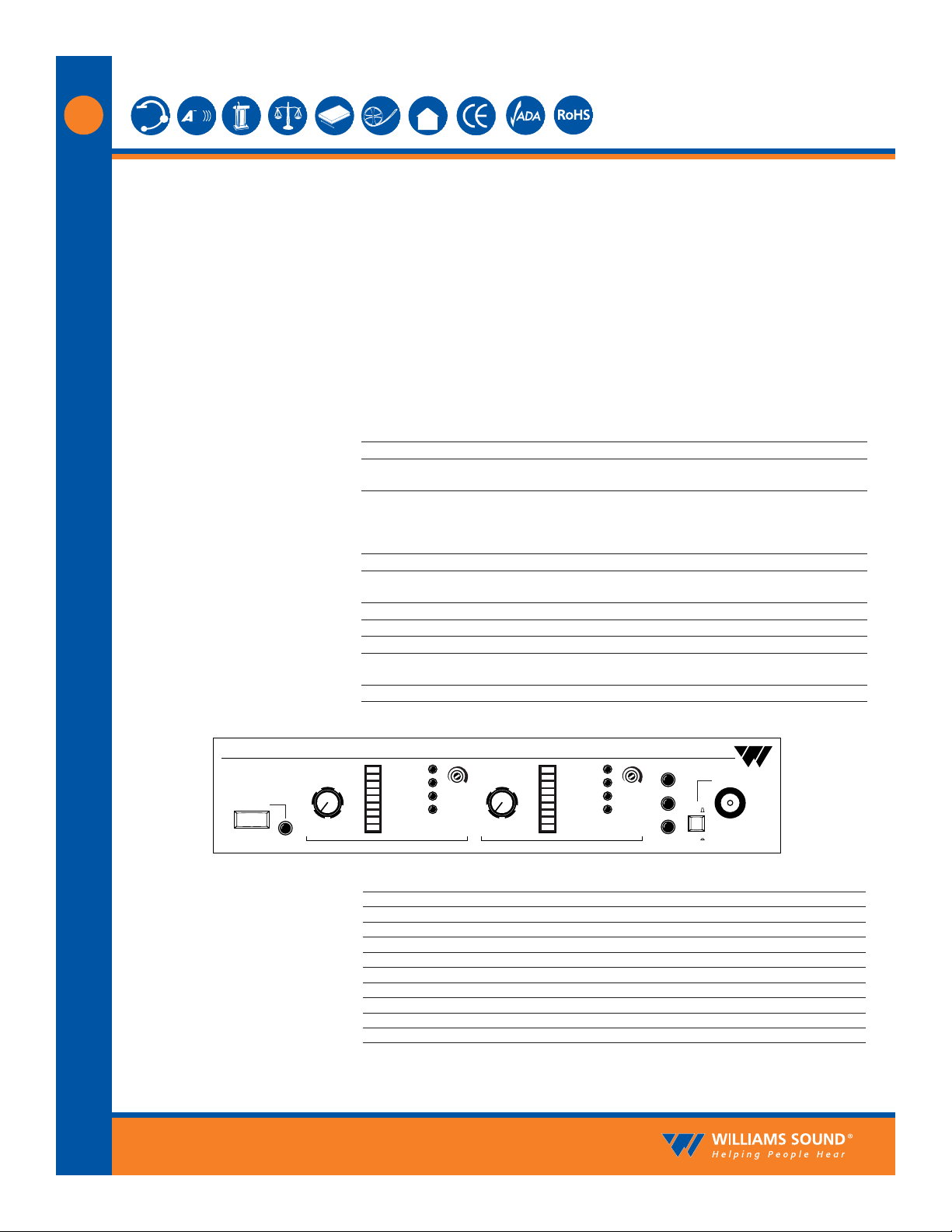
Fig. 1: MOD 232 Front Panel
Power Switch: Two-position push button, ON/OFF
Power Indicator: Green LED
Audio Level Controls: CHA and CHB Input Level, rotary knobs
Audio Indicators: CHA and CHB Audio Level, 10-segment LED’s
Carrier LEDs: 4 green LED carrier “on” indicators per channel (indicates frequency, malfunctions)
Compress Control: 1:1 to 4:1
Input Mix LED: Indicates inputs A and B audio are mixed and transmitted by CHA, CHB off
Stereo LED: Indicates stereo mode
Phones Switch: Selects CH1 or CH2 for phones when not in stereo mode
Phones Output: 1/4" TRS headphone jack. Accepts stereo, mono, and any impedance phones.
Infrared Test LED: IR LED for receiver testing, monitoring, and audio signal testing.
ADA COURTROOM ASSISTIVE LISTENING SYSTEM
SoundPlus
®
Language Interpretation System • Model WIR SYS 4
SoundPlus®Language Interpretation System • Model WIR SYS 4
D
D
©2006, Williams Sound Corp. MCAT 030D
2
NOTE: SPECIFICATIONS SUBJECT TO CHANGE WITHOUT NOTICE!
Dimensions, Weight: 11.25" W x 6.25" H x 2.125" D (28.6 cm x 15.9 cm x 5.4 cm), 1.9 lbs (0.9 kg)
Color: Black with white legends, red acrylic lens
Power Supply: Wall Transformer, 24 VAC, 50-60 Hz, 35 VA, 3-pin MOLEX Connector
North America: TFP 010, UL/CSA
Europe: TFP 027-01, 2-pin Schuko plug, CE
UK: TFP 027-02, 3-pin UK plug, CE
Note: Each WIR TX9 requires its own power supply
Power Cable: NEC Class 2 wiring, two-conductor, 18 ga, 200’ (61 m) max. length
Indicators: Green LED power indicator, red LED baseband indicator
Carrier Frequency: 50 kHz to 8 MHz
Emitter IR Power: 3.5 watts
Coverage Area: 28,000 ft2(2,600 m2) in single-channel mode when using the RX22-4 or RX12-4 Receiver
18,000 ft2(1,700 m2) in two-channel mode when using the RX22-4 or RX12-4 Receiver
3,500 ft2(325 m2) in single-channel mode when using the RX14-2 Receiver
3,063 ft2(285 m2) in single-channel mode when using the RX16 Receiver
(See coverage area diagrams)
Baseband Input: BNC, 100 mV per carrier, 50 Ω, for use with WIR TX9 or MOD 232 only
Baseband Output: BNC, 50 Ω, for use with TX9 only
Baseband Cable: RG 58 Coax, BNC connectors, maximum 1000' (300 m) length
Operating Requirements: 0-50º C ambient temperature, non-condensing, non-corrosive atmosphere
Mounting Kits: Wall or Ceiling Mount: BKT 024 Omnidirectional mount, Mic Stand Kit: SS-11 or SS-6
Warranty: 5 years on Emitter, 90 days on accessories
Approvals: CE, FCC, RoHS, WEEE
Compatible Receivers: WIR RX22-4 Four-Channel Receiver, RX14-2 Two-Channel Receiver,
RX16 Two-Channel Receiver
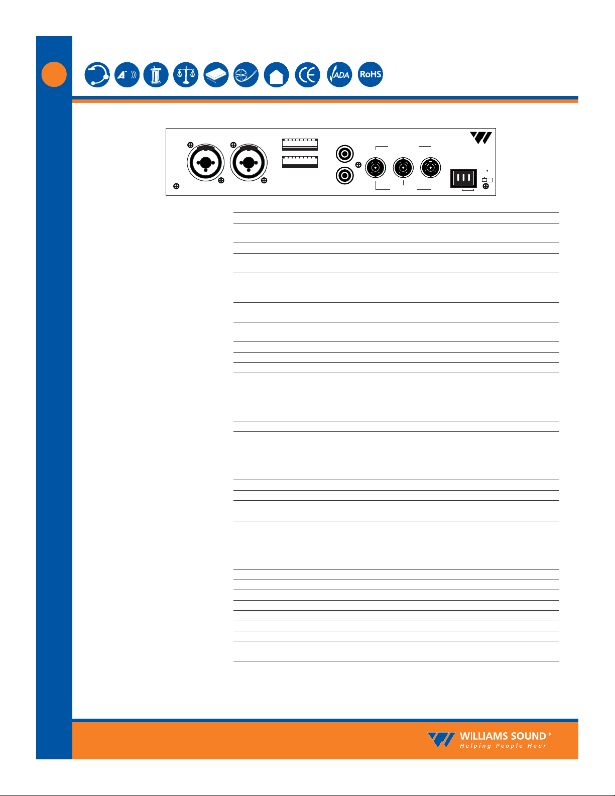
Configuration
Switches
Input CH A Input CH B
Audio Line
Output
CH A
CH A
CH B
CH B
50 Ohms
100 Ohms
Made in USA
24V
24 VAC, 15 VA, 50-60 Hz
Power In
Baseband
Input Output Output
MOD 232 Infrared System Modulator
Plug
Williams Sound
12345678
12345678
Fig. 2: MOD 232 Rear Panel
Power Input: 3-Pin Molex, 24 VAC, 50-60 Hz, 15 VA
Audio Input Jack: CHA and CHB combination XLR/TRS jack
Mic Level: Balanced, Lo-Z, 100 µV min. to 90 mV max., 1mV nominal, 3 kΩ input impedance, sup-
plies switchable simplex power per DIN 45596 for condenser mics
Line Level: Balanced or unbalanced, 21 mV min. to 10 V max., 212 mV nominal, 100 kΩ
Audio Line Output Jacks: RCA Jack, CHA and CHB, 500 mV, unbalanced, 100 Ω source impedance, load imped-
ance must be greater than 1kΩ
Configuration Switches: CHA and CHB 8-position DIP switch, selects Mic/Line input, compressor gain, simplex
power, discrete or mixed inputs, carrier frequency, channel disable, auto shut-off
timer
Baseband Input Jack: BNC, allows mixing with additional MOD 232 Modulator (4CH operation), 100mV, 50Ω
input impedance, use with MOD 232, BNC, RG-58 Cable
Baseband Output Jack: Two BNC jacks carry baseband signal, 100 mV/channel, 50 Ω source impedance, for use
with WIR TX9 or MOD 232 only
Approvals: CE, FCC, RoHS, WEEE
Operating Requirements: 0-50º C ambient temperature, non-condensing, non-corrosive atmosphere
Warranty: 5 years on modulator, 90 days on accessories
WIR TX9 Emitter:
SoundPlus
®
Language Interpretation System • Model WIR SYS 4
SoundPlus®Language Interpretation System • Model WIR SYS 4
D
D
©2006, Williams Sound Corp. MCAT 030D
3
NOTE: SPECIFICATIONS SUBJECT TO CHANGE WITHOUT NOTICE!
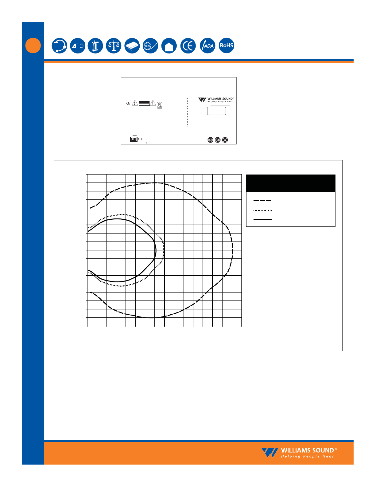
Fig. 3: WIR TX9 Rear Panel
Fig. 4: Receiver Coverage Area with TX9 Emitter in Single Channel Mode
The coverage area for the TX9 will vary depending on the receiver being used. The diagram above
demonstrates the receiver coverage when operating a single TX9 emitter in single channel mode.
Patterns are direct radiation patterns.
Note: Reflections of the infrared light from walls, ceilings and floors may change these patterns.
RX22-4
RX14-2
RX16
90
Feet
80
70
60
50
40
30
20
10
0
-10
-20
-30
-40
-50
-60
-70
-80
-90
0
Feet
10
20
Multi-Channel Infrared Transmitter
Class 1
LED Product
Note: It is normal for this unit to feel warm while it is in operation.
Power Supply Wiring:
Use NEC, Class 2 Wiring, 18 ga. minimum,
200 ft. (70m) maximum length (18 ga.)
Baseband Signal Wiring:
Use RG58 Coax,1000 ft. (350m) max. length
Williams Sound Corp., Minneapolis, Minnesota, USA
Patent Pending
Power In:
24VAC
~
50-60Hz
35VA
40
30
RoHS
CAUTION
RISK OF ELECTRIC SHOCK
DO NOT OPEN
WARNING: TO REDUCE THE RISK OF FIRE OR
ELECTRIC SHOCK DO NOT EXPOSE THIS
EQUIPMENT TO RAIN OR MOISTURE.
Made in U.S.A.
24 VACNC
Plug
Power On Baseband On
80
70
60
50
www.williamssound.com
Mounting
Bracket
Baseband Signal Wiring:
Use 50 Ohm Coaxial Cable (RG58)
Baseband
(Modulation)
InOut Out
50 Ohms
90 100 110 120 130 140 150 160
Receiver Coverage Area with TX9
Transmitter in Single Channel Mode
RX22-4 Receiver
RX14-2 Receiver
RX16 Receiver
SoundPlus
®
Language Interpretation System • Model WIR SYS 4
SoundPlus®Language Interpretation System • Model WIR SYS 4
D
D
©2006, Williams Sound Corp. MCAT 030D
4
NOTE: SPECIFICATIONS SUBJECT TO CHANGE WITHOUT NOTICE!
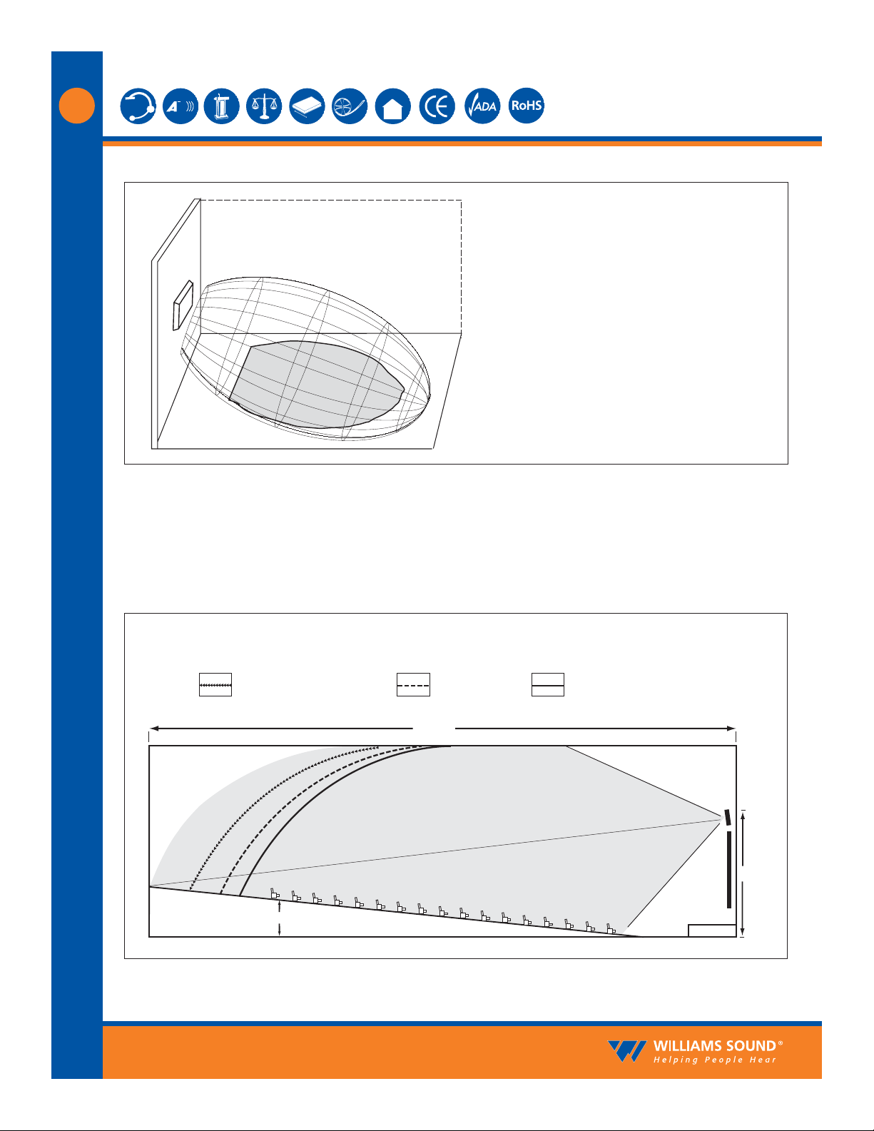
To determine the best location for the emitter, it helps to think of the IR emitter as an invisible floodlight. You’ll want to aim it so the listeners are “flooded” with the infrared light. The emitter should also
be positioned high enough so it won’t be blocked by people and other physical obstructions. See Figure
6 below. Mount the emitter at least 2 ft. (.61 m) above the audience. Position the emitter to face in a
slightly downward angle, 20°, that will increase the “throw” of the infrared beam.
Fig. 5: 3-Dimension Foot Pattern
Fig. 6: Vertical Beam Spread
The TX9 floods the listening audience with a
cone shape light pattern as shown here.
Minimum Receiver Range When Operating with a TX9 Emitter in Single Channel Mode
The path of the cone shape light leaves a
pattern on the ground, or "foot print, " and
indicates where the strongest receiver
reception will occur.
The actual coverage area will vary depending
on the sensitivity of the receiver being used.
Refer to Figures 4 and 7 to determine how
many emitters are required for 100% coverage
of the listening area.
RX22-4 Receiver:
150' (45 m)
Center Of Emitter Beam
6'
RX14-2: 80' (24 m) RX16: 70' (21 m)
(Range)
TX9
30'
SCREEN
STAGE
 Loading...