

Williams Sound TX925 User Manual
INFRARED SPECIFICATION DATA
Simultaneous Interpretation • Audio Description • Media Rooms • Conferences • Boardrooms •
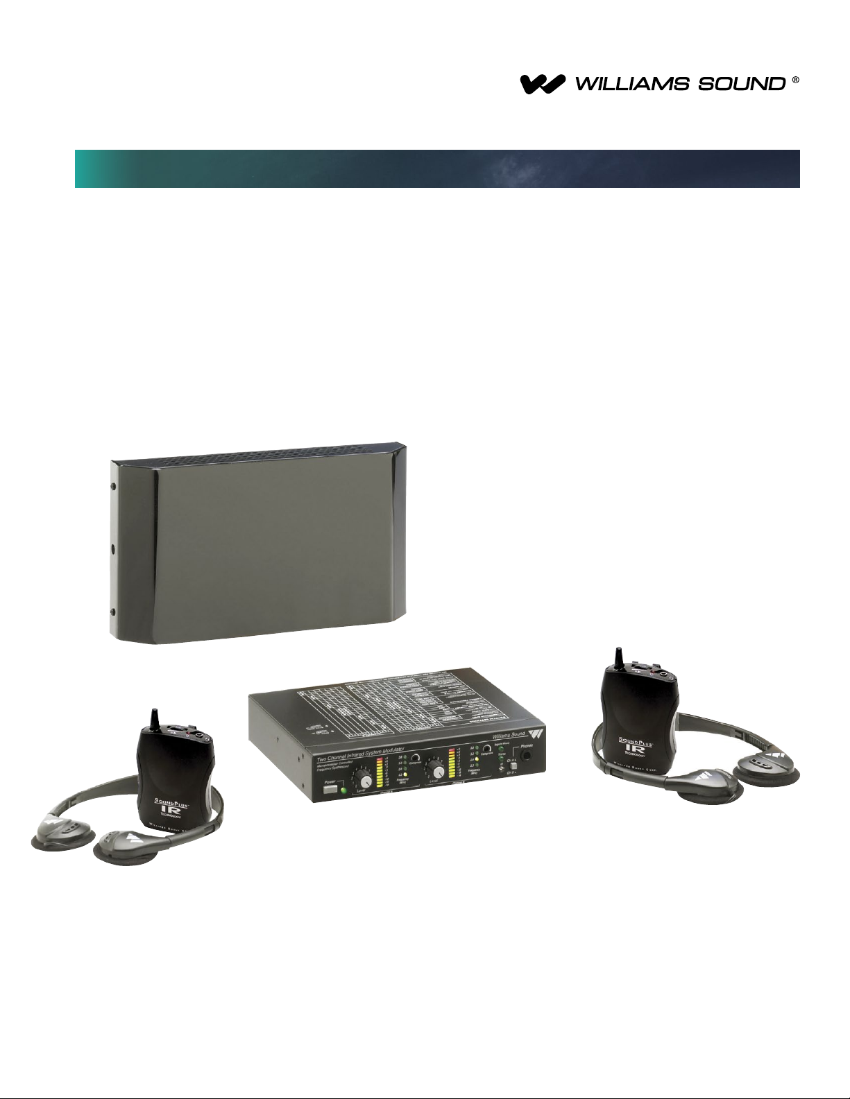
WIR TX925
SoundPlus® Infrared System
The WIR TX925 is ideal for simultaneous language interpretation
for up to two languages. It can operate up to 18,000 sq ft in two
channel mode or up to 28,000 in single channel mode. Operating
on 2.3 and 2.8 MHz, the WIR TX925 is less susceptible to
traditional radio and lighting interference. Listen to the program
with the optional RX22-4 four-channel receiver, RX15-2 two
channel receiver or the RX18 two-channel/stereo receiver.
Courtrooms • Schools • Universities • Cinemas • Churches
SoundPlus® Infrared System
MOD 232 Modulator:
Size, Weight:
Color:
Rack Mount:
Power Supply:
North America:
Europe:
UK:
Modulation:
Carrier Frequency:
Channel B:
Signal-to-Noise Ratio:
Frequency Response:
Total Harmonic Distortion:
Audio Processing:
Switchable compression gain:
Auto Carrier Shut-Off:
8.5” W x 8.2” D x 1.7” H (21.5 cm x 20.8 cm x 4.4 cm), 3.1 lbs (1.5 kg)
Black epoxy paint with white legends
1/2 rack space wide, 1 rack space high, one or two modulators may be mounted in a
single IEC rack space with RPK 005 (single) or RPK 006 (double) Rack Mount Kits
Wall Transformer, 24VAC, 50-60 Hz, 15VA
TFP 016, UL/CSA
TFP 027-01, 2-pin Schuko plug, CE
TFP 027-02, 3-pin UK plug, CE
FM Wideband, +50kHz deviation, 50uS pre-emphasis
Channel A: Selectable, 2.3/2.8/3.3/3.8 MHz,
Selectable, 2.3/2.8/3.3/3.8 MHz
More than 60dB
30 to 16,000 Hz, +1 dB, -3 dB, electrical response
Less than 2%, electrical response
Compression (slope) adjustable from 1:1 or 2:1
Moderate: 16 dB. Max: 33 dB
15-minute timer shuts off carrier when no audio is present (can be disabled)
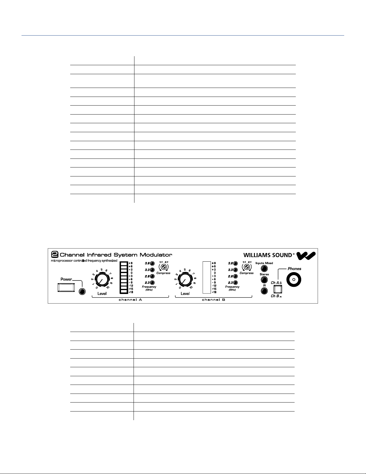
Fig. 1: MOD 232 Front Panel
Power Switch: Two-position push button, ON/OFF
Power Indicator: Green LED
Audio Level Controls: CH A and CH B Input Level, rotary knobs
Audio Indicators: CH A and CH B Audio Level, 10-segment LED’s
Carrier LEDs: 4 green LED carrier “on” indicators per channel (indicates frequency, malfunctions)
Compress Control: 1:1 or 2:1
Input Mix LED: Indicates inputs A and B audio are mixed and transmitted by CHA, CHB off
Stereo LED: Indicates stereo mode
Phones Switch: Selects CH1 or CH2 for phones when not in stereo mode
Phones Output: 1/4” TRS headphone jack. Accepts stereo, mono, and any impedance phones.
Infrared Test LED: IR LED for receiver testing, monitoring, and audio signal testing.
NOTE: SPECIFICATIONS SUBJECT TO CHANGE WITHOUT NOTICE!
SoundPlus® Infrared System
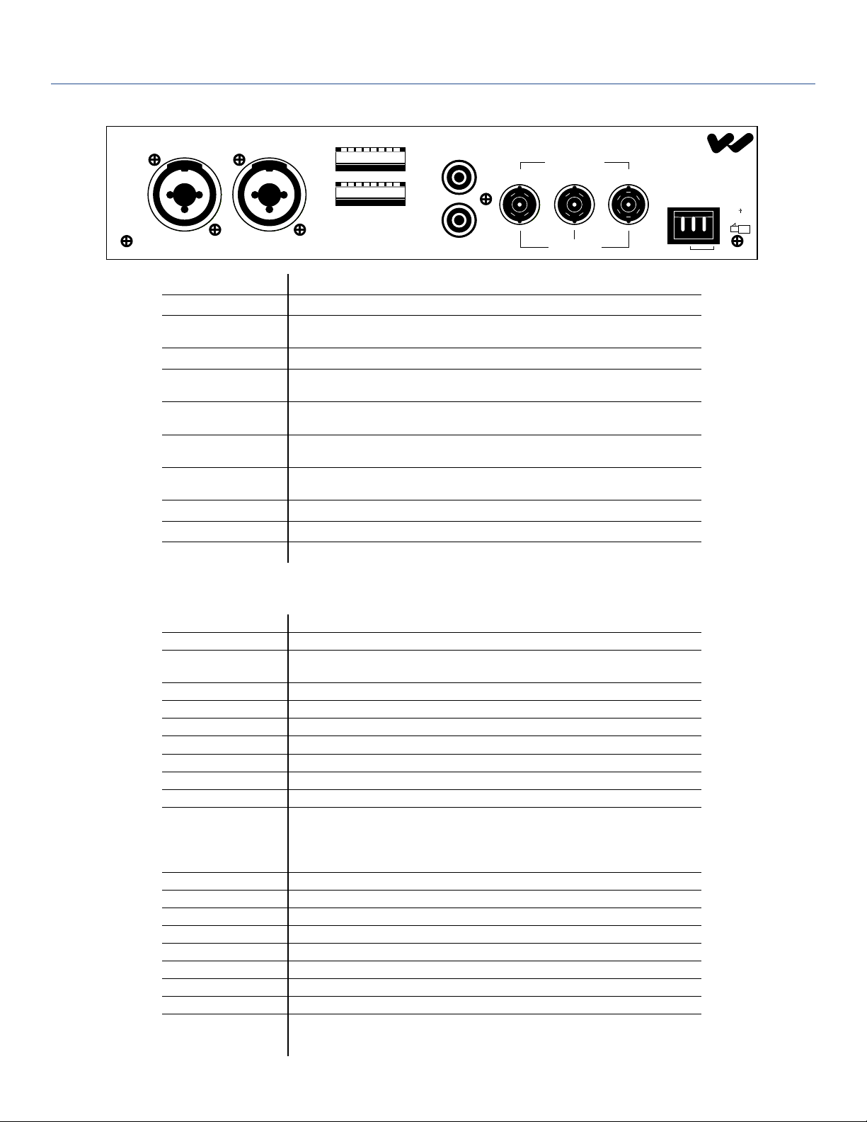
Fig. 2: MOD 232 Rear Panel
Input CH A Input CH B
Made in USA
Power Input:
Audio Input Jack:
Mic Level:
Line Level:
Audio Line Output
Jacks:
Conguration Switches:
Baseband Input Jack:
Baseband Output Jack:
Approvals:
Operating Requirements:
Warranty:
Audio Line
CH A
12345678
Output
CH A
12345678
CH B
Configuration
Switches
3-Pin Molex, 24 VAC, 50-60 Hz, 15 VA
CH A and CH B combination XLR/TRS jack
Balanced, Lo-Z, 100 µV min. to 90 mV max., 1mV nominal, 3 kΩ input impedance, supplies
switchable simplex power per DIN 45596 for condenser mics
Balanced or unbalanced, 21 mV min. to 10 V max., 212 mV nominal, 100 kΩ
RCA Jack, CH A and CH B, 500 mV, unbalanced, 100 Ω source impedance, load impedance
must be greater than 1kΩ
CHA and CHB 8-position DIP switch, selects Mic/Line input, compressor gain, simplex
power, discrete or mixed inputs, carrier frequency, channel disable, auto shut-off timer
BNC, allows mixing with additional MOD 232 Modulator (4CH operation), 100mV, 50Ω input
impedance, use with MOD 232, BNC, RG-58 Cable
Two BNC jacks carry baseband signal, 100 mV/channel, 50 Ω source impedance, for use with
WIR TX9 or MOD 232 only
CE, FCC, RoHS, WEEE
0-50º C ambient temperature, non-condensing, non-corrosive atmosphere
5 years on modulator, 90 days on accessories
CH B
100 Ohms
MOD 232 Infrared System Modulator
Baseband
Input Output Output
50 Ohms
Williams Sound
Power In
24 VAC, 15 VA, 50-60 Hz
Plug
24V
WIR TX9 Emitter:
Dimensions, Weight:
Color:
Power Supply:
North America:
Europe:
UK:
Power Cable:
Indicators:
Carrier Frequency:
Emitter IR Power:
Coverage Area:
Baseband Input:
Baseband Output:
Baseband Cable:
Operating Requirements:
Mounting Kits:
Warranty:
Approvals:
Compatible Receivers:
11.25” W x 6.25” H x 2.125” D (28.6 cm x 15.9 cm x 5.4 cm), 1.9 lbs (0.9 kg)
Black with white legends, red acrylic lens
Wall Transformer, 24 VAC, 50-60 Hz, 35 VA, 3-pin MOLEX Connector
Note: Each WIR TX9 requires its own power supply
TFP 010, UL/CSA
TFP 027-01, 2-pin Schuko plug, CE
TFP 027-02, 3-pin UK plug, CE
NEC Class 2 wiring, two-conductor, 18 ga, 200’ (61 m) max. length
Green LED power indicator, red LED baseband indicator
50 kHz to 8 MHz
3.5 watts
28,000 sq. ft. (2600 sq. m) in single channel mode when using the RX22-4 Receiver
18,000 sq. ft (1700 sq. m) in two channel mode when using the RX22-4 Receiver
11,000 sq. ft (1000 sq. m) in four channel mode when using the RX22-4 Receiver
3,500 sq. ft (325 sq. m) in single channel mode when using the RX15-2 Receiver
3,063 sq. ft (285 sq. m) in single channel mode when using the RX18 Receiver
(See coverage area diagrams)
BNC, 100 mV per carrier, 50 Ω, for use with WIR TX9 or MOD 232 only
BNC, 50 Ω, for use with TX9 only
RG 58 Coax, BNC connectors, maximum 1000’ (300 m) length
0-50º C ambient temperature, non-condensing, non-corrosive atmosphere
Wall or Ceiling Mount: BKT 024 Omnidirectional mount, Stand Kit: SS-11 or SS-6
5 years on Emitter, 90 days on accessories
CE, FCC, RoHS, WEEE
WIR RX22-4 Four-Channel Receiver
WIR RX18 Two-Channel Receiver
WIR RX15-2 two channel receiver
NOTE: SPECIFICATIONS SUBJECT TO CHANGE WITHOUT NOTICE!
 Loading...