

Page 1

®
Ma n u a l a n d us e r Gu i d e
Hearing Helper™ T800 Transmitter
Wireless FM Listening System
Transmitter Model T800
Optional Receiver Model R863
MAN XXX © 2008 Williams Sound Corp.
Page 2

®
Hearing Helper™ T800 Tr a n s M i T T e r
Ma n u a l a n d us e r Gu i d e
Co n T e n T s Pa G e
System Overview .....................................................................3
T800 Transmitter Instructions ................................................ 4-6
Features and Controls ......................................................... 4
Antenna Connection ........................................................... 4
Power Connection .............................................................. 4
Selecting a Frequency ......................................................... 5
Connecting an Audio Source .............................................. 5
Adjusting the Audio Source .............................................. 5-6
Receiver Safety Information .................................................. 7-8
R863 Receiver Instructions ................................................... 9-13
Features & Controls ............................................................ 9
R863 Belt Clip Instructions ............................................... 11
Receiver Battery Information ......................................... 12-13
Receiver Charger Information ................................................14
Troubleshooting Guide ........................................................ 15-16
Warranty ............................................................................... 17-18
System Specications .............................................................19
2
Page 3
®
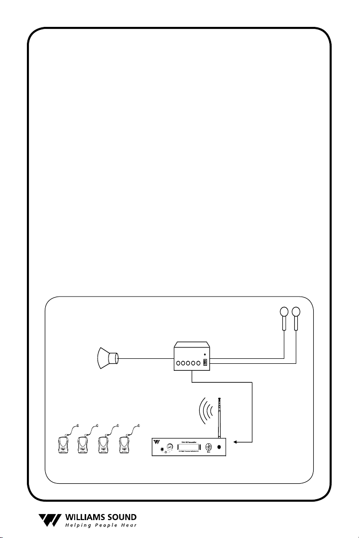
sy s T e M ov e r v i e w
Sound System Amplifier
Loudspeakers
Mics
Line-Level Output
R863 Wide-band
Receivers w/Earphones
Line-Level Input
T800 Transmitter
Thank you for purchasing the Hearing Helper™ T800
transmitter from Williams Sound Corp. This wide-band FM
transmitter operates on the 863 MHz bandwidth and connects directly to your facility’s sound system; alternatively,
it can used with a microphone as a stand-alone system. The
T800 is designed for use with the optional R863 FM receiver
to provide hearing assistance or language interpretation to a
listening audience.
The T800 transmitter operates much like an FM radio station.
The transmitter picks up the audio directly from the facility’s
mic or sound system which are broadcasted over an FM radio
signal. Listeners use the R863 receivers equipped with headsets to pickup the FM broadcast up to 400 feet away.
To avoid difculties, please read through these instructions as
you begin to use the system. Then save the manual for questions that arise as you continue to use your system. If at any
time you are having problems with this product, please contact
Williams Sound toll free for assistance: +1 952 943 2252.
Fi g. 1: Ov e r a l l Sy S t e m Di a g r a m
3
Page 4
®
se T T i n G u P T h e T800
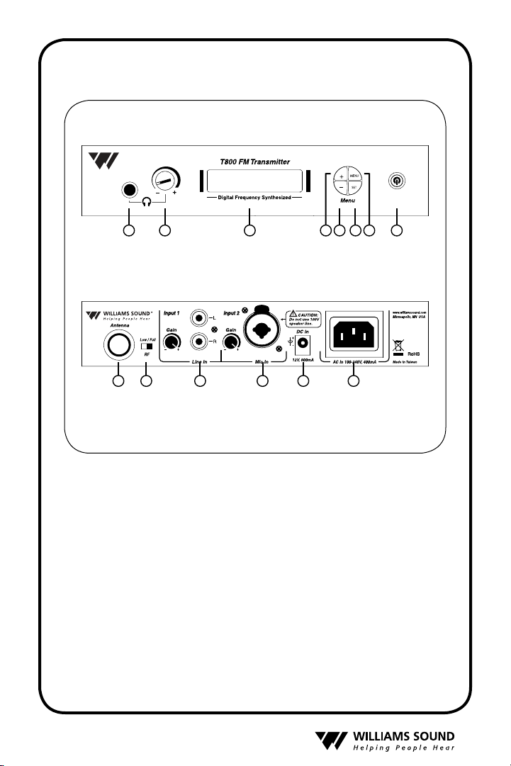
Fi g.2:Fe a t u r e S &co n t r o l S
1
2 3 54 6 7 8
1. Headphone Jack
2. Headphone Volume Control
3. Frequency Display (LCD)
4. Up Button
5. Down Button
6. Set Button
7. Menu Control
8. Power ON/OFF Control
10 12 1413
9
9. Antenna Connector
10. RF Power Output Switch
11. Audio Input Jack, RCA Type
(Line-level, Unbalanced) with
Gain Control
• St e p 1:Se l e c t lo c a t i o n
Position the T800 transmitter near the audio source (i.e. sound
system, mixer) from which it will receive audio.
t e p 2:in S t a l l t h e an t e n n a
• S
Gently thread the antenna onto the stud recessed in the hole on
the back of the transmitter. To use a remote antenna, contact
your dealer or Williams Sound.
• S
t e p 3:co n n e c t t h e po w e r
Locate the power supply cord equipped with the 3-pin connector, then plug the connector into the “AC Power In” jack
located in the back of the T800. Plug the power supply into
the AC outlet. Press the “Power ON/OFF” control on the front
4
11
12. Mic Input Jack, Combo 3-Pin XLR
or 1/4” TRS (Balanced/unbalanced)
with Gain Control
13. DC Power In Jack
14. AC Power In Jack
Page 5

®
of the unit. On power up, “Williams Sound T800” will appear
briey while the system initializes. The system will then display the current operating “CHANNEL” (1-16).
• St e p 4:Se l e c t t h e Fr e q u e n c y
The T800 operates on the 863-864 MHz bandwidth with sixteen selectable preset channels. Channels 1-3 are standard and
coincide with channels 1-3 on the R863 (optional) receiver:
CH 1 = 863.250 MHz, CH 2 = 863.750 MHz, CH 3 = 864.750 MHz
Non-standard operating channels (4-16) available are:
CH 4 = 863.050 MHz, CH 5 = 863.400 MHz, CH 6 = 863.550 MHz
CH 7 = 864.000 MHz, CH 8 = 864.150 MHz, CH 9 = 864.300 MHz
CH 10 = 864.450 MHz, CH 11 = 864.600 MHz, CH 12 = 864.950 MHz
CH 13 = 863.150 MHz, CH 14 = 863.650 MHz, CH 15 = 863.900 MHz,
CH 16 = 864.850 MHz
The T800 is set at the factory to Channel 1 (863.250 MHz).
To change the channel, press and hold the “Set” button for 3
seconds (cursor will ash), then press the “+” Up or “-” Down
button until the desired channel (1-16) is displayed. No further
action is required, the selection will be saved into memory
after 3 seconds.
To view the current operating frequency (i.e. “863.250 MHz”)
on the T800, press the “MENU” button once. To change the
operating frequency, press and hold the “Set” button for 3
seconds (cursor will ash), then press the “+” Up or “-” Down
button until the desired frequency is displayed. The selection
will be saved into memory after 3 seconds.
• St e p 5:co n n e c t t h e au d i o So u r c e
On the back of the T800, two audio input jacks are available:
an RCA-type jack for line-level, unbalanced audio sources;
and a combo XLR (3-pin) and 1/4” TRS jack for connecting
unbalanced/balanced audio sources. Connect the desired audio
source to the T800 transmitter and proceed to Step 6.
5
Page 6
®
• St e p 6:ad j u S t t h e a u d i o le v e l
Locate the “Gain Control” on the rear of the T800. With
the audio source playing, use a small screwdriver or tuning
wand to rotate the “Gain Control” clockwise “+” to increase
or counterclockwise “-” to decrease gain. Monitor the audio
indicator “bars” on the display as you make your adjustments.
As a general guideline:
No audio indicator bars present = Audio source is TOO LOW.
Some audio indicator bars present = Audio source is ACCEPTABLE
“Limiting” message is displayed = Audio source is TOO HIGH.
Ensure the audience is receiving the highest quality
audio: listen to the audio through the headphone
jack on the front of the T800 (FIG. 2).
• St e p 7:li S t e n w i t h a n FMre c e i v e r
IMPORTANT: The FM receiver being used with the T800
transmitter will need to be on the same frequency as the transmitter!
Install the receiver batteries, plug in the earphone, turn on the
receiver and walk around the listening area. The signal should
be clear and quite loud when the volume is turned up. See
page 9 for detailed operating instructions on the R863 receiver.
6
Page 7

®
sa f e T y in f o r M a T i o n
he a r i n g Sa F e t y :
CAUTION!
The R863 receiver is designed to amplify sounds to a high
volume level which could potentially cause hearing damage if
used improperly.
To protect your hearing and the hearing of others:
1. Make sure the volume is turned down on the receiver before
putting on the earphone or headphone. Then adjust the volume
to a comfortable level.
2. Set the volume level at the minimum setting that you need to
hear.
3. If you experience feedback (a squealing or howling sound), reduce the volume setting and move the microphone away from
the earphone or headphone.
4. Do not allow children or other unauthorized persons access to
the receiver.
Ba t t e r y Sa F e t y a n d di S p o S a l :
CAUTION!
The R863 receiver is supplied with disposable Alkaline batteries. Do not attempt to recharge disposable batteries, which
may explode, release dangerous chemicals, cause burns, or
other serious harm to the user or product.
7
Page 8

®
pa c e M a k e r Sa F e t y :
CAUTION!
1. Before using the R863 receiver with a pacemaker or other
medical device, consult your physician or the manufacturer of
your pacemaker or other medical device.
2. If you have a pacemaker or other medical device, make sure
that you are using this product in accordance with safety
guidelines established by your physician or the pacemaker
manufacturer.
re C y C l i n G in s T r u C T i o n s
Help Williams Sound protect the environment! Please take the
time to dispose of your equipment properly.
Product Recycling for Customers in the European Union:
Please do NOT dispose of your Williams Sound equipment in
the household trash. Please take the equipment to an electronics recycling center; OR, return the product to the factory for
proper disposal.
Battery Recycling for Customers in the European Union:
Please do NOT dispose of used batteries in the household
trash. Please take the batteries to a retail or community collection point for recycling.
8
Page 9

®
us i n G T h e oP T i o n a l r863 re C e i v e r
O
On/Off/Channel
Selector Switch
Volume Control
Earphone/Headphone Jack
"On" Indicator LED
Fig.3:r863re c e i v e r vi e w S
R863 Top
R863 Front
9
Page 10

®
us i n G Th e r863 re C e i v e r , C o n T .
Note: Rechargeable batteries are shipped in a discharged state
and must be charged overnight before using.
1. Make sure there are two alkaline or rechargeable AA batteries in the Receiver. If batteries are not installed, see Battery
Information on page 12-13.
2. Plug the earphone or headphone into the “ ” Jack on top of
the Receiver.
3. Put on the earphone or place the headphones over your ears.
4. Turn the unit on: turn the On/Off/Channel switch to position
“1” or “2” or “3.” The Power “ON” LED indicator should illuminate Red.
5. Select a desired operating frequency. To operate on 863.25
MHz, turn the On/Off/Channel switch to position “1”; to operate on 863.75 MHz, turn to position “2”; to operate on 864.75
MHz, turn to position “3.”
Important: Make sure the receiver is operating on the same fre-
quency as the transmitter! The receiver’s channel switch
(1-2-3 position) should match the transmitter’s channel switch.
6. Adjust the receiver volume control to a comfortable listening
level.
You should be able to hear someone speaking into the trans-
mitter microphone.
The receiver can be placed in a pocket, or clipped onto a belt,
harness, or waistband.
IMPORTANT: When the R863 receiver is not being used,
remember to turn the unit OFF by turning the On/Off/Channel switch to the “ ” power icon position. The Power “ON”
LED indicator should not be lit.
10
Page 11

®
Be l T Cl i P in s T a l l a T i o n f o r T h e r863 re C e i v e r
toin S t a l l :
Position the belt clip on the rear of the R863 receiver as shown
in FIG. 4A. Turn the belt clip 180º left or right as shown in
FIG. 4B. The belt clip is now installed and ready for use.
O re m O v e :
t
Turn the belt clip 180º so the open end of the clip points to the
top of the unit as shown in FIG. 4A. Gently pull the belt clip
away from the unit to remove.
Fi g.4a Fi g.4B
11
Page 12

®
r863 re C e i v e r Ba T T e r y in f o r M a T i o n
Battery
Compartment
Battery Selection
Switch
Note Proper
Polarity
in S t a l l a t i o n
Open the battery compartment by lifting the tab on the back
of the transmitter or receiver with your nger. To remove
depleted batteries, pull up on the fabric strip.
IMPORTANT: If Alkaline (non-rechargeable) batteries
are being installed, slide the battery selection switch in the
battery compartment to the “Alkaline” position. See FIG.
5 below. If installing NiMH (or rechargeable) batteries,
slide the battery selection switch to the “NiMH” position.
Press the batteries into place over the fabric strip. Be sure
to observe proper polarity (+/-). Damage due to improper
battery installation may void the warranty on the product.
Close the battery door. LED will ash when the batteries are
getting low; continue to use until the sound becomes weak or
distorted, or the unit quits operating, then replace or recharge
batteries.
Fi g.5:Bat te ry in S t a l l a t i o n
12
Page 13

®
no n -r e c h a r g e a B l e Ba t t e r i e S
In normal use, two AA 1.5 V alkaline batteries (BAT 001) will
last approximately 40 hours in the R863 receiver. If the sound
becomes weak or distorted, replace the batteries. Do not leave
dead batteries in the receiver. Battery corrosion is not covered
by the Williams Sound warranty.
re c h a r g e a B l e Ba t t e r i e S
The R863 receiver can use rechargeable AA batteries (BAT
026). On an overnight charge, these NiMH batteries are designed to operate for 30 hours in the R863 receiver.
Note: The battery installed in the receiver may be recharged
in the receiver only if it is a NiMH battery, and only if a
Williams Sound CHG 3512, CHG 3512 PRO, or CHG 3502
Multi-Charger is used. Damage from improper charging is not
covered by the Williams Sound warranty.
IMPORTANT WARNINGS:
DO NOT ATTEMPT TO RECHARGE ZINC CARBON (“HEAVY DUTY”) , ALKALINE, OR LITHIUM
BATTERIES! DO NOT ATTEMPT TO RECHARGE
DISPOSABLE BATTERIES!
These batteries may heat up and explode, causing possible injury and damage to the equipment.
Avoid shorting the plus and minus battery terminals together with metal objects. Battery damage and burns can
result! Do not dispose of batteries in re. Do not open
batteries - toxic chemicals inside.
NOTE: Rechargeable batteries are shipped in a discharged
condition. They must be charged for a complete charge cycle
before the rst use. Rechargeable batteries will need to be
replaced after 1-2 years of use.
13
Page 14

®
oP T i o n a l Ba T T e r y Ch a r G e r s f o r T h e r863 re C e i v e r
Receiver or
T r ansmitter
Charging
LED Indicator
AC P o wer Connection
CHG 3502
Rear View
Fi g:6a:chg3512/3512proMu l t i -ch a r g e r
Fi g:7a:chg3502du a l -Ba y ch a r g e r
14
For more information on available chargers, visit
www.williamssound.com or call +1 952 943 2252.
Page 15

®
Tr o u B l e sh o o T i n G Gu i d e
Read through the manual and user guide carefully to verify
proper setup and installation of your system.
Transmitter frequency display (LCD) not lit.
•
Make sure the AC power adapter is plugged into the transmitter.
•
Make sure the electrical outlet is on.
No sound through receivers.
•
If some of the receivers work, but others don’t, check for bad
batteries or earphones on the receivers that aren’t working.
•
Verify that the receiver frequency matches the transmitter frequency. See “Select the Frequency” section.
•
If none of the receivers work, check to see if the power is connected to the transmitter and the frequency display on the front
of the transmitter is illuminated.
•
Check to see if the transmitter is connected properly to the
sound system.
•
Turn the screwdriver-adjust “Gain Control” on the back of the
T800 transmitter clockwise to increase the audio level.
•
If you are not using an input signal from a sound system, make
sure the Williams Sound microphone is plugged into the “Mic
Input” jack on the rear of the T800 transmitter.
•
Make sure the antenna is installed and connected properly.
Insufcient range, good reception near transmitter, poor at a
distance
˛•Check to see if the antenna was installed correctly. If not, cor-
rect or replace the antenna. The signal should be clearly audible
at least 100 ft. with line of site to transmitter.
˛•Check to make sure no other transmitters (or other devices) are
transmitting on the same frequency (channel).
15
Page 16

®
Sound through receivers is loud, but distorted. Noise (room
noise or electronic noise) seems to grow after talking stops.
“Limiting” appears on LCD display.
•
Turn the “Gain Control” on the back of the T800 counterclockwise to decrease the audio level.
Sound through the receivers is weak and noisy.
•
Turn the “Gain Control” on the back of the T800 clockwise to
increase the input signal strength. .
•
Increase the input signal level from the sound system.
Buzzing or humming noise in sound system.
•
There is nothing wrong with the T800 transmitter. One or more
pieces of equipment in the sound system are being disturbed by
RF (Radio Frequency) signals produced by the T800. The most
likely suspects are your amplier, mixer, or tape deck. The RF
gets into the other equipment primarily through the power cord,
speaker wires, or unshielded inputs, all of which can act as
antennas. Try the following steps:
•
Move the transmitter away from the other sound equipment.
•
Make sensitive equipment more immune to RFI/EMI. The
manufacturers of your audio equipment may offer application
notes for this purpose. Williams Sound offers a document giving suggestions for improving RF immunity in existing audio
equipment. (Technical Bulletin: Buzz Or Hum In The Sound
System, FRM 531) Unless you have the necessary technical
skills, this is best left to a qualied electronics repair technician.
16
Page 17

®
li M iT ed wa r r a n T y
Williams Sound products are engineered, designed, and manufactured under carefully controlled conditions to provide you
with many years of reliable service. Williams Sound warrants
the Hearing Helper™ T800 transmitter against defects in ma-
terials and workmanship for FIVE (5) years. During the rst
ve years from the purchase date, we will promptly repair or
replace the Hearing Helper™ T800 transmitter .
Microphones, earphones, headphones, batteries, cables, carry
cases, and all other accessory products carry a 90-day warranty. Chargers carry a 1 year warranty.
WILLIAMS SOUND HAS NO CONTROL OVER THE
CONDITIONS UNDER WHICH THIS PRODUCT IS USED.
WILLIAMS SOUND, THEREFORE, DISCLAIMS ALL WARRANTIES NOT SET FORTH ABOVE, BOTH EXPRESS AND
IMPLIED, WITH RESPECT TO THE HEARING HELPER™
T800 TRANSMITTER, INCLUDING BUT NOT LIMITED
TO, ANY IMPLIED WARRANTY OF MERCHANTABILITY
OR FITNESS FOR A PARTICULAR PURPOSE. WILLIAMS
SOUND SHALL NOT BE LIABLE TO ANY PERSON OR
ENTITY FOR ANY MEDICAL EXPENSES OR ANY DIRECT, INCIDENTAL OR CONSEQUENTIAL DAMAGES
CAUSED BY ANY USE, DEFECT, FAILURE OR MALFUNCTIONING OF THE PRODUCT, WHETHER A CLAIM
FOR SUCH DAMAGES IS BASED UPON WARRANTY,
CONTRACT, TORT OR OTHERWISE. THE SOLE REMEDY
FOR ANY DEFECT, FAILURE OR MALFUNCTION OF
THE PRODUCT IS REPLACEMENT OF THE PRODUCT.
NO PERSON HAS ANY AUTHORITY TO BIND WILLIAMS
SOUND TO ANY REPRESENTATION OR WARRANTY
WITH RESPECT TO THE HEARING HELPER™ T800
TRANSMITTER. UNAUTHORIZED REPAIRS OR MODIFICATIONS WILL VOID THE WARRANTY.
The exclusions and limitations set out above are not intended
to, and should not be construed so as to contravene mandatory
provisions of applicable law. If any part or term of this Dis-
17
Page 18

®
claimer of Warranty is held to be illegal, unenforceable, or in
conict with applicable law by a court of competent jurisdiction, the validity of the remaining portions of this Disclaimer
of Warranty shall not be affected, and all rights and obligations
shall be construed and enforced as if this Limited Warranty did
not contain the particular part or term held to be invalid.
If you experience difculty with your system, call for Customer Assistance:
+1 952 943 2252
If it is necessary to return the system for service, your Customer Service Representative will give you a Return Authorization
Number (RA) and shipping instruction.
Pack the system carefully and send it to:
Williams Sound Corp.
Attn: Repair Dept.
10321 West 70th Street
Eden Prairie, MN 55344 USA
Your warranty becomes effective the date you purchase your
system. Your returned warranty card is our way of knowing
when you warranty begins. Please take a moment to ll it out
and mail the enclosed card. You may also register your product
online: www.williamssound.com/registration.aspx. This information will help us serve you better in the future. Thank you!
18
Page 19

®
he a r i n G he l P e r™ T800 Tr a n s M i T T e r
Dimensions: 21.8 cm (8.6”) W x 21.8 cm (8.6”) D x 4.6 cm (1.8”) H
Weight: 1.32 kg (2.9 lbs)
Color: Black with white legends
Power:
DC: 12 to 13 VDC, 800 mA, 2.1 mm DC input jack
Power Switch: Push ON - push OFF switch with red light
Temperature Range: Operating: 0 C to 40 C (+32 F to 104 F)
Storage: -20 C to 70 C (-4 F to +158 F)
Operating Frequencies:
Ch 3 = 864.750 MHz,
13 other frequencies available (see manual)
RF Output: 5 to 10 dBm (full power switch)
RF Switch: Low/ Full power switch on rear panel
LCD Display: Backlit, Ch #, frequency, user name, audio level VU
(indicated by 11 segments total)
Menu Push Buttons: Menu, +Ch select, -Ch select, SET
Headphone Output: Mono, 1/4” tip barrel jack, 0.35mW power into 33 ohms, level
adjust on front panel
Stability: +/- .05 MHz (0 C to 40 C)
FM Deviation: 45 kHz (line input, L+R, 1 kHz, 0.5 Vrms)
Pre-Emphasis: 50 µsec
Nominal Range: Up to122 meters (400 ft.) at RF switch full power with
Williams Sound R863 receiver
Frequency Response:
Microphone input: 110 to 8.5 kHz +/- 3 dB
Signal/Noise Ratio (1 KHz):
Microphone input: > 40 dB
%THD + noise (1 KHz):
Microphone input: < 0.5%
Audio Processing: 2:1 compression (line or microphone input)
Audio Input: Line input: mono, RCA jack x 2 (labeled left and right)
Microphone input: Balanced/ unbalanced, combo XLR (3 pin)
or 1/4” TRS jack.
Audio Levels: (at FM deviation)
Line input: 0.5 Vrms (-6 dBV), rotary gain adjust rear panel at
maximum
Microphone input: 10 mVrms (-40 dBV), rotary gain adjust
rear panel at maximum
Common Mode Rejection:
Antenna: 22.9 cm (9”) long, semi exible, adjustable, removable, rear
panel connector
Compatible Receivers:
Approvals: CE, RoHS, WEEE, ETSI EN 301 357-1, 2
Warranty: 3 years (excluding accessory products)
NOTE: SPECIFICATIONS SUBJECT TO CHANGE WITHOUT NOTICE!
AC: 100 to 240 VAC, 50-60 Hz, 400 mA, power inlet IEC C14
Selectable: Ch 1= 863.250 MHz, Ch 2 = 863.750 MHz,
Line input: 25 to 10.0 kHz +- 3 dB
Line input: > 50 dB
Line input: < 0.4%
Microphone input: > 22 dB @ 1 kHz, balanced input
R863
19
Page 20

®
10321 West 70th St., Eden Prairie, MN 55344 U.S.A.
800.843.3544 | 952.943.2252 | FA X: 952.943.2174
www.williamssound.com
©2008 Williams Sound Corp. MAN XXX
 Loading...