

Page 1
Presentation-style conferences for up to 14 languages, where a floor and a single relay language are used.
IC-2
Interpreter Control Console
SPECIFICATION DATA
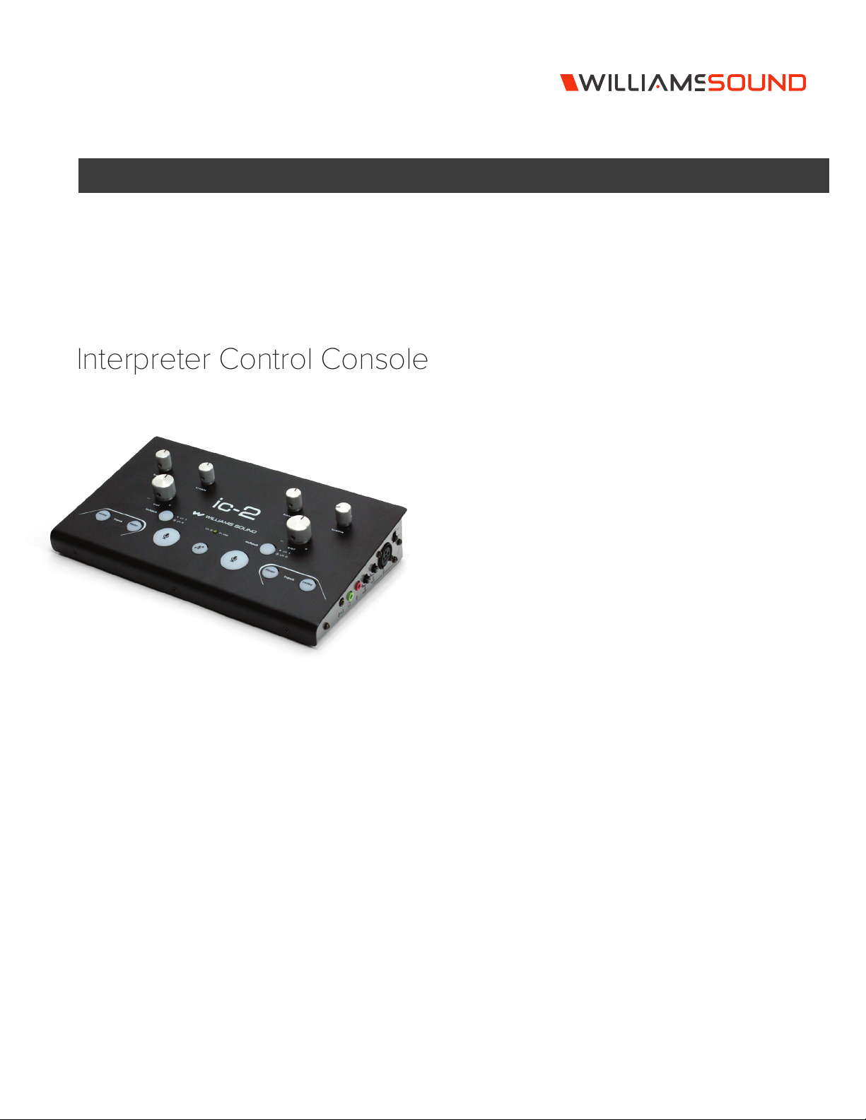
The Williams Sound IC-2 is an audio control center for
simultaneous interpretation of one or more languages. As a
stand-alone unit, it allows one or two interpreters to monitor
floor or relay sources, activate microphone inputs, and route the
interpretation signal to one of two language groups. Ideal for
presentation-style conferences for up to 14 languages, where a
floor and a single relay language are used. Can be used with
Williams Sound FM, IR and Digi-Wave™ transmitters for portable or
fixed installations. Designed to meet international standards for
portable interpretation consoles.
Features
• CAT5 audio bus oers simplified cabling, easy cascading to
support additional interpreters.
• Built-in distribution amplifier and mini mixer reduce the need for
external equipment and greatly simplify setup.
• Floor language feed-through
• Interlocking microphone and CH2 (relay) output functions
• Soft-touch buttons provide for smoother, quieter operation
• Enhanced flexibility, providing each interpreter with multiple
microphone and headset options
• Individual volume and tone controls ensure optimal listening
levels
• Five-year warranty
© 2019, Williams AV, LLC MCAT 091J
Page 2
IC-2 Interpreter Control Console
A167
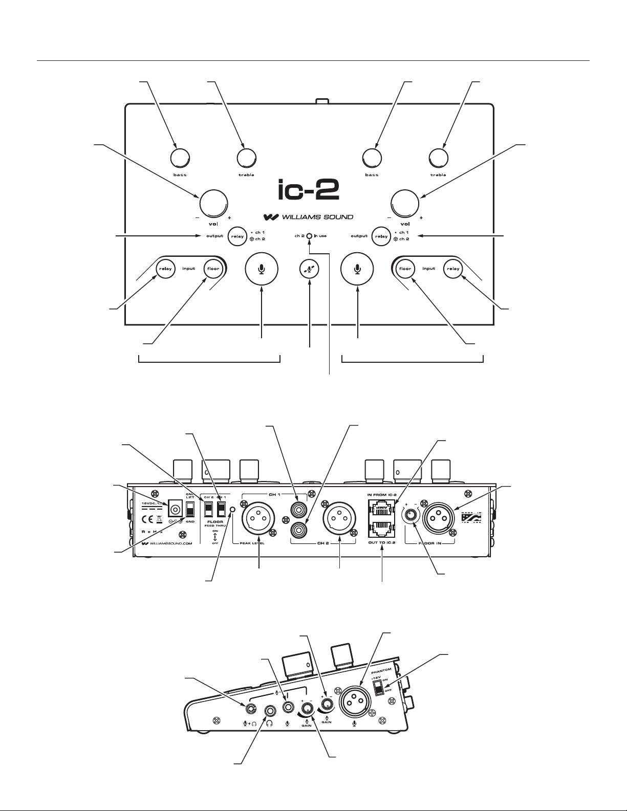
BASS TREBLE BASS TREBLE
VOLUME
CH1 / CH2
OUTPUT
RELAY INPUT
FLOOR INPUT
CH2
FEEDTHROUGH
CH1
FEEDTHROUGH
INTERPRETER (B)
CH1 OUT
RCA JACK
MIC ON MIC ON
MUTE
“CH2 IN USE” LED
CH2 OUT
RCA JACK
VOLUME
CH1 / CH2
OUTPUT
RELAY INPUT
FLOOR INPUT
INTERPRETER (A)
A165
IC-2 BUS IN
POWER JACK
GROUND LIFT
PEAK LEVEL
INDICATOR
ELECTRET MIC AND
HEADPHONE JACK
HEADPHONE JACK
XLR CH1 OUTPUT FLOOR IN
XLR MIC LEVEL
ELECTRET MIC JACK
XLR CH2 OUTPUT
IC-2 BUS OUT
ELECTRET MIC LEVEL
XLR FLOOR IN
LEVEL CONTROL
A166
XLR MIC JACK
PHANTOM POWER
© 2019, Williams AV, LLC MCAT 091J
Page 3

IC-2 Interpreter Control Console
Signal Schematics
SIGNAL DISTRIBUTION
PA
FLOOR
FLOOR
INPUT SELECTION
FLOOR SELECTED
FLOOR IN
RELAY
IC-2
IC-2
RELAY
IC-2 IC-2
FLOOR
INTERPRETER
CH2 SELECTED
(FROM IC-2 BUS)
OUTPUT SELECTION
CH1 ON (DEFAULT SETTING, NO LIGHT)
MIC IN
CH2 ON
MIC IN
IC-2
IC-2
IC-2
INTERPRETER
CH1 OUT
CH2 OUT
A168
© 2019, Williams AV, LLC MCAT 091J
Page 4

IC-2 Interpreter Control Console
IC-2 Specifications
Dimensions/Weight/Color 10” (25.4cm) x 6.35” (16.1cm) x 2.45” (6.2cm) / 3.4 lbs (1.5 kg) / Black and Silver
Power External Power Supply, 18VDC Desktop Style Switching Inverter, 110-240VAC, 50-60Hz, 1A
INPUTS / OUTPUTS
Floor In 3-pin XLR female jack, balanced (or unbalanced) input with 24k Ω dierential input impedance, max balanced input is +19dBu
IC-2 Bus In / Out CAT5 8p8c RJ45 female receptacle, distributes balanced line level Floor and Relay audio to another IC-2
XLR Microphone Inputs 3-pin XLR female jack, balanced (or unbalanced) input. Switchable 12VDC simplex power. Variable gain of 58 dB, 2.4k Ω balanced
3.5mm Microphone Inputs Stereo 3.5 mm TRS phone jack, pink, and stereo 3.5mm TRRS phone jack, black, unbalanced (r,s) for electret condenser mics,
3.5mm TRRS Headphone Output 3.5mm TRRS phone jack, Tip = Left, Ring 1 = Right, Ring 2 = GND, Sleeve = Mic. 40mW max power into 32 Ω stereo headset.
3.5mm Headphone Output 3.5mm TRS phone jack, mono or stereo headphone, 8 Ω minimum. 190mW max power into 32 Ω stereo headset.
CH1 Out, CH2 Out 3-pin XLR male jack, balanced output. Max output is +19dBu into 600 Ω balanced load impedance.
RCA Jacks Red: RCA jack for recording and CH1 audio, Interpreter audio only, no feedthrough.
CONTROLS
Volume Left and Right rotary, controls headphone volume
Bass and Treble Tone Left and right rotary with center detent, controls headphone bass and treble tone levels.
Floor Input, Relay Input Push buttons, backlit blue, select listening language group. Listening modes are either/or: turning one on disables the other.
CH2 Output Push button, backlit yellow, selects microphone output language group: light on = CH2 Out, light o = CH1 Out.
Gain Adjust Rotary gain pots control level of microphone and Floor audio.
Phantom Power Slide switch enables 12VDC Simplex power to XLR microphone.
CH1 Feedthrough Slide switch enables Floor feedthrough to Norm Out XLR jack.
CH2 Feedthrough Slide switch enables Floor feedthrough to Relay Out XLR jack.
Ground Lift Slide switch disconnects Chassis and Audio Grounds internal to the console.
INDICATOR
Peak Level Indicator Green LED on back panel indicates optimal audio output level on Norm Out XLR when blinking.
CH2 Output in Use Indicator Yellow LED on front panel indicates when CH2 is in use.
AUDIO OUTPUT
Frequency Response 45Hz to 20kHz, +0/-3dB re: 1kHz with flat bass/treble
Distortion at 1kHz <0.5% THD @ full power
Signal to Noise Ratio >82dB @ 1kHz
Crosstalk Attenuation >63dB @ 1kHz
Tone Controls Bass: +12dB Boost or -12dB Cut @ 100Hz
Approvals and Declarations CE, FCC, Industry Canada, RoHS, C-Tick, CB
Warranty 5 years, parts and labor (90 days on accessories)
input impedance, maximum balanced input is +19 dBu
variable gain of 40dB. Bias is 3.7VDC through 2.7k Ω
White: RCA jack for recording CH2 audio.
Mute Push button, backlit red, mutes left and right mics while pressed.
Mic On Push button, backlit bright red, activates microphone. Right and left Mic On buttons are interlocked; mic can only be turned on if
the other is o.
Treble: +12dB Boost or -12dB Cut @ 10kHz
© 2019, Williams AV, LLC MCAT 091J
Page 5

IC-2 Interpreter Control Console
Architectural and Engineering Specifications:
The IC-2 is an audio control center powered by an 18VDC universal
(100 – 240 VAC) power supply. It shall be housed in a black and
grey steel enclosure 10” x 6.35” x 2.45”.
Top
The IC-2 shall have individual rotary volume and tone controls
for two interpreters (L & R). Input and output selection is selected
with soft touch buttons for smooth quiet operation. The console
shall have two selectable listening modes (blue, relay and floor)
and two selectable output modes (yellow, CH1 and CH2). The unit
shall have two microphone select buttons (red when activated) and
microphone (push and hold) for mute.
Rear
Each unit shall have an RJ-45 input and output for interconnection
to additional IC-2s via CAT5 audio bus cable eliminating the need
for additional distribution amplifiers. It shall have an XLR floor in jack
with gain control. It shall have XLR and RCA CH2 and CH1 outputs.
It shall have switchable CH1 and CH2 selection and ground lift
capability.
Sides
It shall have one XLR audio input jack for microphone with its own
rotary gain control and switchable 12V power supply for each
interpreter (L & R). It shall have 3.5mm microphone input (with rotary
gain control) and 3.5mm headphone output jacks. Each side shall
also have a 3.5mm combination headset jack for use with iPhone
style headsets.
This unit shall be the Williams Sound model IC-2.
Domestic Sales
Williams AV
10300 Valley View Rd
Eden Prairie, MN 55344
Ph: 800-328-6190 / 952-943-2252
FAX: 952-943-2174
Email: info@williamsav.com
Web: www.williamsav.com
International Sales
International Sales Department
Williams AV
10300 Valley View Rd
Eden Prairie, MN 55344 USA
Phone: +1 952 943 2252
Fax: +1 952 943 2174
Email: info@williamsav.com
Web: www.williamsav.com
info@williamsav.com / www.williamsav.com
800-843-3544 / INTL: +1-952-943-2252
© 2019, Williams AV, LLC MCAT 091J
 Loading...