

Page 1
Williams Sound
®
Helping People Hear
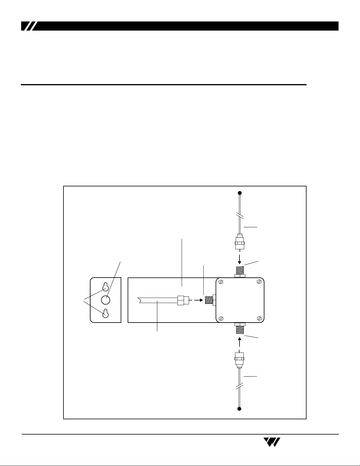
Coax Feedline
(Cable should exit
antenna at right angle
as shown.)
Antenna Rod
Finger-tight
Connection
Finger-tight
Connection
Finger-tight
Connection
Antenna Rod
Pass-Through Hole
(For Conduit Installations)
Mounting
Holes
Antenna Bracket
Dipole Antenna Set Up Instructions
Model ANT 024
CONTAINS:
1 - Antenna Bracket (BKT 016) with connectors
2 - 16" Antenna Rods (ANT 017)
20' - RG59 Coax Feedline with "F" Connectors
6 - Self-tapping screws (FSS 668 BK)
6 - 5/16" nylon cable clamps (PLC 006)
DESCRIPTION
The ANT 024 is a 75 Ohm, shortened dipole, designed for operation at 72-76 MHz. It is
intended for use with Williams Sound Receivers and the T4 or T35 Transmitters.
ANT 024 SET-UP
© 2005, Williams Sound Corp. MAN 073F
Page 2

Williams Sound
®
Helping People Hear
BRACKET-ANTENNA ASSEMBLY PROCEDURE:
Step 1: Select a mounting location for the Antenna Bracket.
It is best to locate the antenna high on a wall, within line-of-sight of the area where the
receivers will be used. Do not mount the antenna behind steel beams or other metal structures.
Radio signals will generally pass through non-metal structures. The antenna can be mounted on
a wall, in a corner, or behind a wooden beam. If possible, avoid placing the antenna within four
feet of steel beams or near structural steel elements. Metal studs, ductwork, and foil-backed
insulation can absorb radio energy, greatly reducing the range of the system.
Step 2: Use the antenna bracket as a template to mark the position of the mounting holes.
Step 3: Attach the antenna bracket to the mounting surface. Use appropriate wall anchors (not includ-
ed) if necessary. If you need to run the feedline through a wall, a 1/2" hole is necessary to pass
the connector through.
Step 4: Attach one of the Antenna Rods to the connector on top of the case. Use fingers only to tighten.
Step 5: Attach the second Antenna Rod to the connector on the bottom of the case. Use fingers only to
tighten.
COAX FEEDLINE CABLE INSTALLATION PROCEDURE:
The Antenna Coax Feedline is a 20' length of RG59 Coaxial Cable. The feedline connects to the Antenna
Connector on the assembly as shown in the figure on page 1.
Step 1: Attach the Coax Feedline to the connector facing the wall. Use fingers only to tighten. Arrange
the Coax Feedline so that it exits the antenna at a right angle.
Step 2: If this is not a conduit installation, use at least one of the nylon cable clamps to support the
weight of the cable.
Step 3: Attach the second cable clamp about 12" away from the first one, maintaining a right angle
between the feedline and the Antenna.
Notes: DO NOT bend the cable sharply at any point. Allow at least a 3" radius for turns.
Up to 100' of feedline can be added without significant line loss. Be sure to use the proper "F"
connectors when adding on to the feedline. The feedline can also be shortened and a new "F"
connector installed, if necessary. Do not coil up excess cable.
The feedline is categorized as Class II wiring. Thus, it may be (but is not required to be) routed
through metal conduit, but NOT with microphone cables or AC power wiring.
2
Page 3

Williams Sound
®
Helping People Hear
RECYCLING INSTRUCTIONS
Help Williams Sound protect the environment! Please take the time to dispose of your equipment
properly.
Product Recycling for Customers in the European Union:
Please do NOT dispose of your Williams Sound equipment in the household trash. Please take the
equipment to a electronics recycling center; OR return the product to the factory for proper disposal.
8/19/05
3
Page 4

Williams Sound Corp.
10321 West 70th St., Eden Prairie, MN 55344
U.S.A. 800-843-3544 / 952-943-2252 / FAX: 952-943-2174
© 2005, Williams Sound Corp. MAN 073F
 Loading...