

Page 1

Savina Sconce
Assembly Instructi ons
CAUTION:
• BEFORE INSTALLING FIXTURE, MAKE SURE THE POWER TO THE CIRCUIT IS TURNED OFF AT THE
MAIN FUSE BOX / CIRCUIT BREAKER UTILITY BOX.
Important Safety Instructions:
• These instructions are provided for your safety. It is very important that they are read carefully and completely
before beginning the assembly and installation of this lighting fixture
• We strongly recommend that a professional electrician install all direct wire fixtures.
• THIS PRODUCT MUST BE INSTALLED IN ACCORDANCE WITH THE APPLICABLE INSTALLATION CODES
BY A PERSON FAMILIAR WITH THE CONSTRUCTION AND OPERATION OF THE PRODUCT AND THE
HAZARDS INVOLV ED .
• The lighting fixture is meant for indoor use. It must be connected only to 3-wire, single-phase electrical supply
systems (provided with Ground wire or equivalent protection system).
• For your safety, it is strongly recommended that two people install the lighting fixture.
• This fixture has been rated for up to E26 one (1) 60-watt maximum TYPE B standard incandescent light bulb
(not included) or one (1) 13-watt compact fluorescent light bulb (not included) or one (1) 9-watt SBLED light
bulb (not included). To avoid the risk of fire, do not exceed the recommended wattage.
• The lighting fixture is meant for indoor use, DRY LOCATIONS ONLY.
• Save these instructions.
WARNING:
• To reduce the risk of fire, el ectrical shock or pers onal injury, always turn off li ght fixture and allow it to cool
prior to replacing light bulb.
• Do not touch bulb when fixture is turned on. Do not look directly at lit bulb.
• Keep flammable materials away from lit bulb.
• This lighting fixture contains lead, a chemical known to the State of California to cause cancer, birth
defects and other reproductive harm. Wash hands after installing, handling, cleaning or otherwise
touching this light fixture.
Pre-assembly:
Remove all parts and hardware from box along with any plastic protective packaging.
Do not discard any contents until after assembly is complete to avoid accidentally discarding small parts or
hardware.
For your safety and convenience, assembly by two people is recommended.
US/CN Page 1 of 7
Page 2
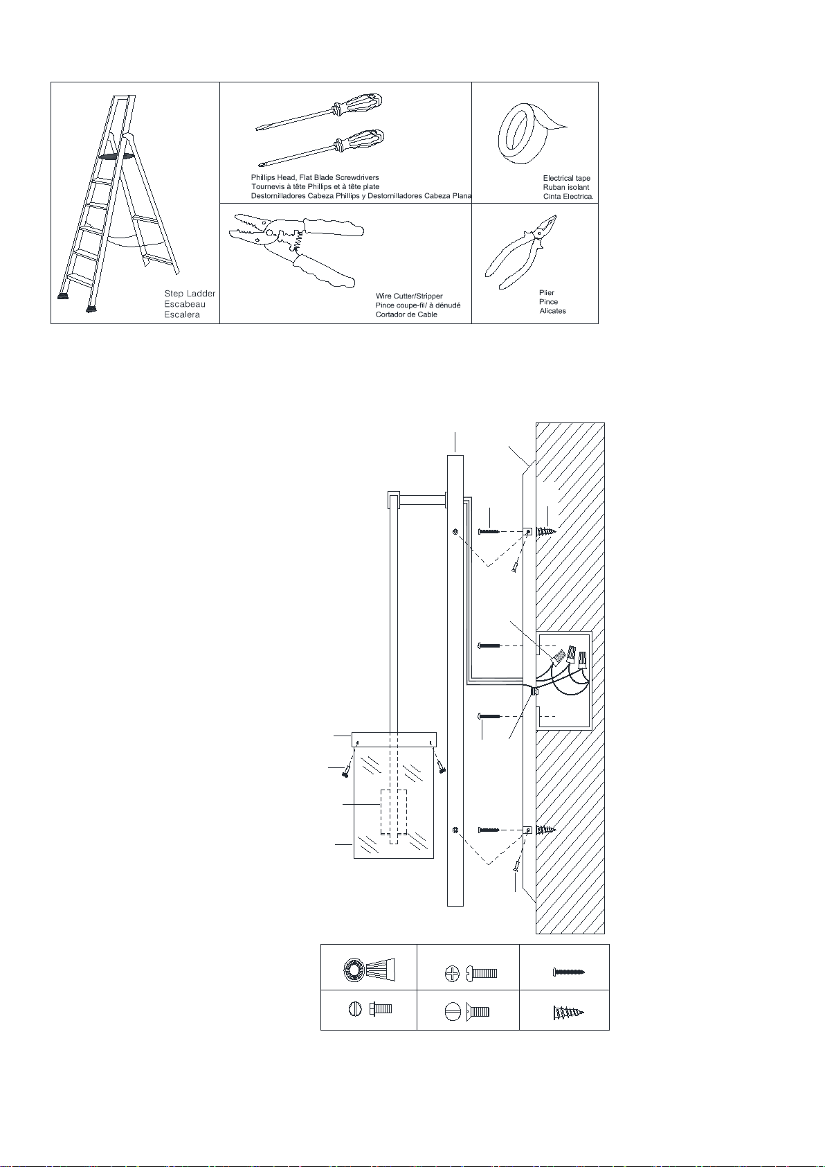
Tools Required: (not included):
A
B
3X
1x
C
2X
D
4X
A
B
C
D
E
G
H
I
F
J
K
L
K
2X
L
2X
Hardware Enclosed:
(A) Plastic Wire Nut Connectors (3)
(B) Green Ground Screw (1)
(C) Mounting Screws (2)
(D) Canopy Screws (4)
(K) Screws (2)
(L) Metal Anchors (2)
Parts Included:
(E) Mounting Plate (1)
(F) Canopy (1)
(G) Socket (1)
(H) Glass Shade (1)
(I) Set Screws (3)
(J) Shade Holder (1)
US/CN Page 2 of 7
Page 3

Assembly Instructions
D
E
F
1
2
A1
E
C
2
3
1
3
A2
SHUT OFF THE MAIN ELECTRICAL SUPPLY FROM THE MAIN FUSE BOX/CIRCUIT BREAKER!
Carefully unpack all fixture parts and hardware and lay them on a clear workspace.
Separate the Mounting Plate (E) from the Canopy (F) by
removing the 4 Canopy Screws (D). Do not discard the
Canopy Screws (D) as these will be used later.
Determine the desired location of the light fixture and
temporarily install the Mounting Plate (E) to the wall J-box
using the 2 J-box Mounting Screws (C), insert and tighten
each screw until the Mounting Plate (E) is firmly secured to
the J-Box.
Mark the 2 round locations of the Mounting Plate (E) on the
wall using a pencil.
US/CN Page 3 of 7
Page 4
E
C
2
1
A3
A4
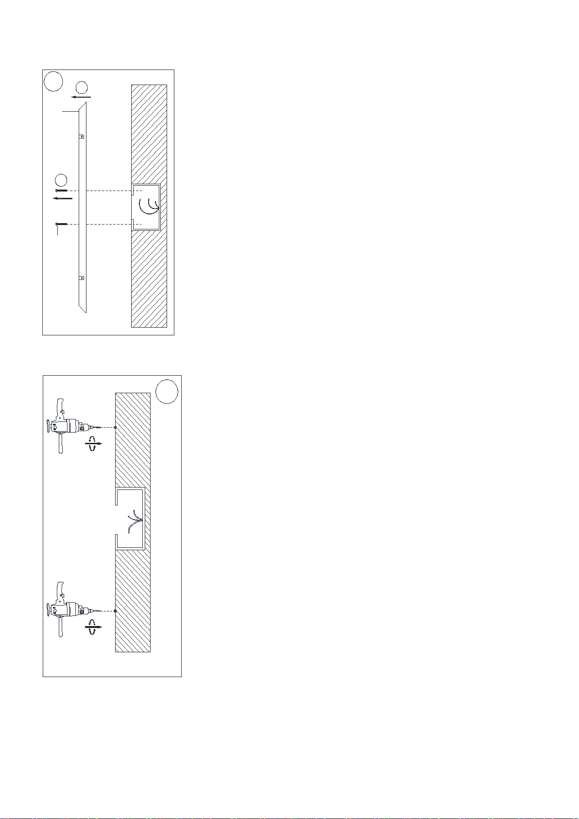
1. Un-install the Mounting Plate (E) from the marked
wall outlet box location by loosening and removing
the 2 J-box Mounting Screws (C) with a screwdriver.
1. Using the drill with the appro priate size drill bit,
drill 1 hole in the wall at each of the 2 marked
round locations for the Metal Anchors (L).
US/CN Page 4 of 7
Page 5
A5
L
E
F
A6
A
1/2 inch
expos ed wi r es
A7
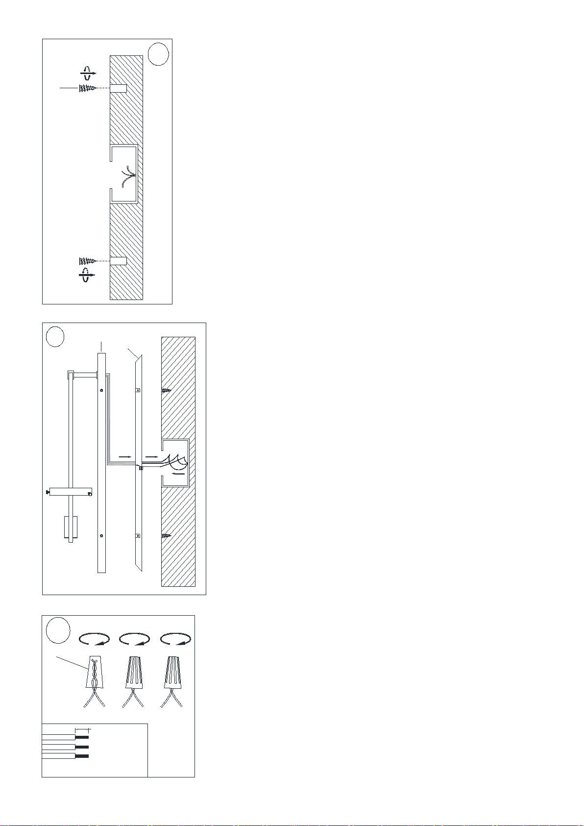
1. Insert the Metal Anchors (L) to the holes on the wall.
1. Feed the fixture power cord and bare ground wire through
Mounting Plate (E).
Please read the section” To Make the Wire Connections” Below.
US/CN Page 5 of 7
Page 6
C
D
E
F
K
L
3
2
4
1
A8
H
I
G
J
A9
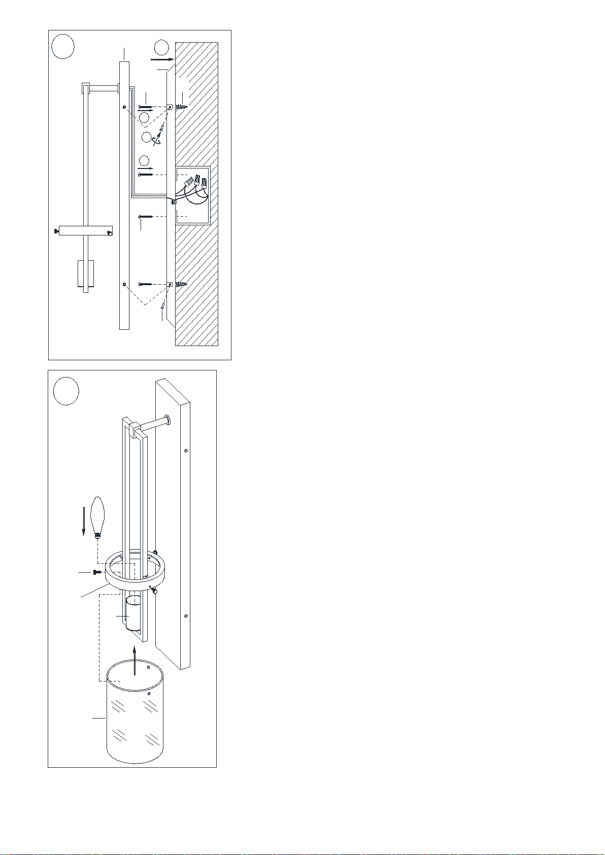
1. Attach the Mounting Plate (E) onto the wall junction box
using Mounting Screws (C).
2. Screw the screws (K) to Metal Anchors (L).
3. Attach the Canopy (F) to th e affixed Mounting Plat e (E)
and secure with Canopy Screws (D).
1. Insert the specified light bulb into the Socket (G).
DO NOT EXCEED THE SPECIFIED WATTAGE.
2. Loosen the Set Scre ws (I) and attach the Glass
Shade (H) to the Shade H older (J) and ti ghten
with Set Screws (I). Do not over-tighten.
US/CN Page 6 of 7
Page 7
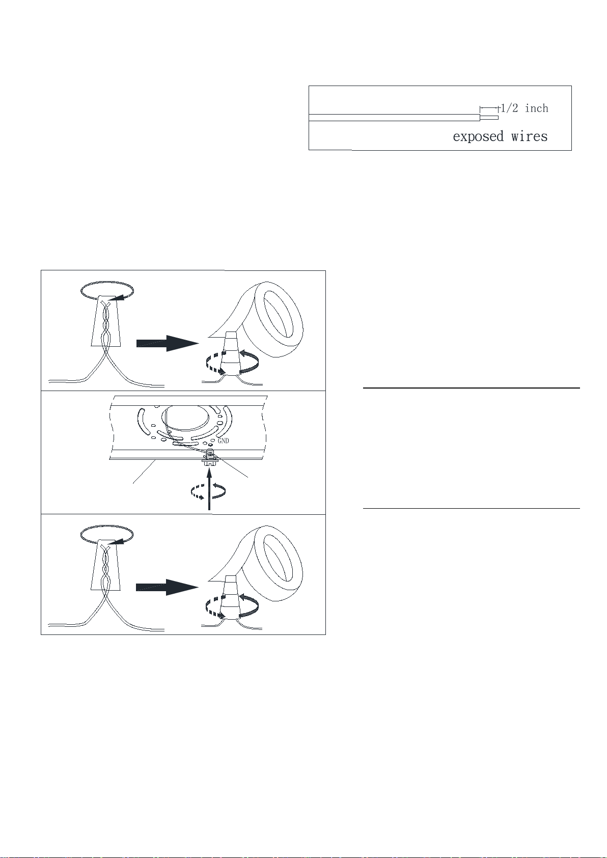
To Make the Wire Connections:
Connect the GROUND FIXTURE
wrap the connection with
1. Gently pull the wiring from the junction box and allow
wires to hang. The HOT or LIVE wire is usually black.
The NEUTRAL wire is usually white. Check to see if
there is a ground wire that is usually green or green
with a yellow stripe or exposed copper metal wire. If
needed, use a pair of wire strippers to remove about
1/2 inch of insulation from each wire.
2. Carefully inspect the fixtures wires. The NEUTRAL FIXTURE WIRE is White. The HOT FIXTURE WIRE is Black.
The GROUND WIRE is green/yellow. If you have any doubt and cannot identify the power-supply wires with
confidence, then we recommend that you ask an electrician and that you not continue with the installation.
3. With the help of another person to hold the weight of the fixture, attach the fixture wires to the junction box wires as
shown in the illustrations.
NOTE:
IT IS IMPERATIVE THAT THE JUNCTION BOX IN YOUR HOME BE PROPERLY GROUNDED!
DO NOT REVERSE THE HOT AND NEUTRAL CONNECTIONS OR SAFETY WILL BE COMPROMISED.
4. Check the wiring connections and if all looks good, gently tuck the wire connections neatly into the junction box
Care instructions:
• Wipe clean with a soft, dry cloth or static duster.
• Always avoid the use of harsh chemicals or abrasive cleaners as they may cause damage to the fixture’s finish.
E
B
Thank you for your purchase
WIRE to the GROUND J-BOX WIRE
using the Plastic Wire Nut Connector
(A) and
electrical tape. Be sure that no wire
strands are exposed.
If the junction box DOES NOT have a
GROUND WIRE, wrap the fixture's bare
ground wire around the Green Ground
Screw (B) and insert the screw into the
Mounting Plate (E), marked as “GND”, and
tighten screw to secure the wire.
Connect the NEUTRAL FIXTURE WIRE to
the NEUTRAL J-BOX WIRE first and then
connect the HOT FIXTURE WIRE to the
HOT J-BOX WIRE using the Plastic Wire Nut
Connectors (A). Wrap these connections
with electrical tape. Be sure that no wire
strands are exposed.
Stores | catalog | www.williams-sonoma.com
USA 1.877.812.6235
US/CN Page 7 of 7
 Loading...