

Page 1
This manual covers the Installation, Operation and Routine Maintenance requirements
for the following Williams Refrigeration products:
Coral Wall Mounted Cabinets
Provided the instructions in this Operating Manual are read and implemented correctly,
the optimum performance and reliability of your equipment should be maintained.
The Williams Coral Wall Mounted Cabinet temperature parameters are set as follows:
General Produce (H): +1°C(34°F) / +4°C (39°F)
Declaration of Conformity References:
Low Voltage Directive 2006/95/EC
Machinery Directive 2006/42/EC
Electromagnetic Compatibility Directive 2004/108/EC
Pressure Equipment Directive 97/23/EC
Waste Electrical and Electronic Equipment Directive (WEEE) 2002/96/EC
Restriction on Use of Certain Hazardous Substances Directive (RoHS) 2002/95/EC
CFC Free Refrigerant
Williams Refrigeration declares that all products manufactured by Williams Refrigeration
comply with the above directives as they apply to those products, and those products are
therefore declared to be in conformity with the provisions of the above legislation.
Model No.:
Serial No.:
OPERATING MANUAL for
CORAL WALL MOUNTED CABINETS
Refrigerant Designation Global Warming Potential
HFC - R134a 1300
HFC - R404a 3260
Page 2
INSTALLATION
Removal of Redundant Cabinets
Please ensure the old/redundant refrigeration cabinets and refrigeration equipment are disposed of safely and legally.
It is recommended that doors are removed prior to disposal in order to ensure safety.
Unpacking
Remove all external and interior packing and accessories. Ensure all such material is disposed of safely.
Selecting a Location for your New Unit
The area on which the unit will rest must be level, free of vibration, and suitably strong enough to support the
combined weights of the unit plus the maximum product load weight.
Ventilation and Clearance
It is essential to ensure that the room in which the unit is to be installed has adequate ventilation. Refrigerators generate
a considerable amount of heat and, if operated in a small unventilated room in warm weather, they will quickly cause the room
temperature to become excessive. This could cause the motor to overheat and possibly damage the windings. At the very
least, such an installation will cause the unit to use an excessive amount of electricity.
In addition to ventilation in a room, a minimum of 150mm clearance above, below and to the side of the unit is required
to ensure efficient and effective performance. Do not block vents by stacking boxes on top or in front of the unit as this
could also effect performance.
Wall Brackets for a Coral
After the final location has been determined, please proceed as follows:
1. Identify a wall that is strong enough to support the combined weight of the unit plus maximum product load.
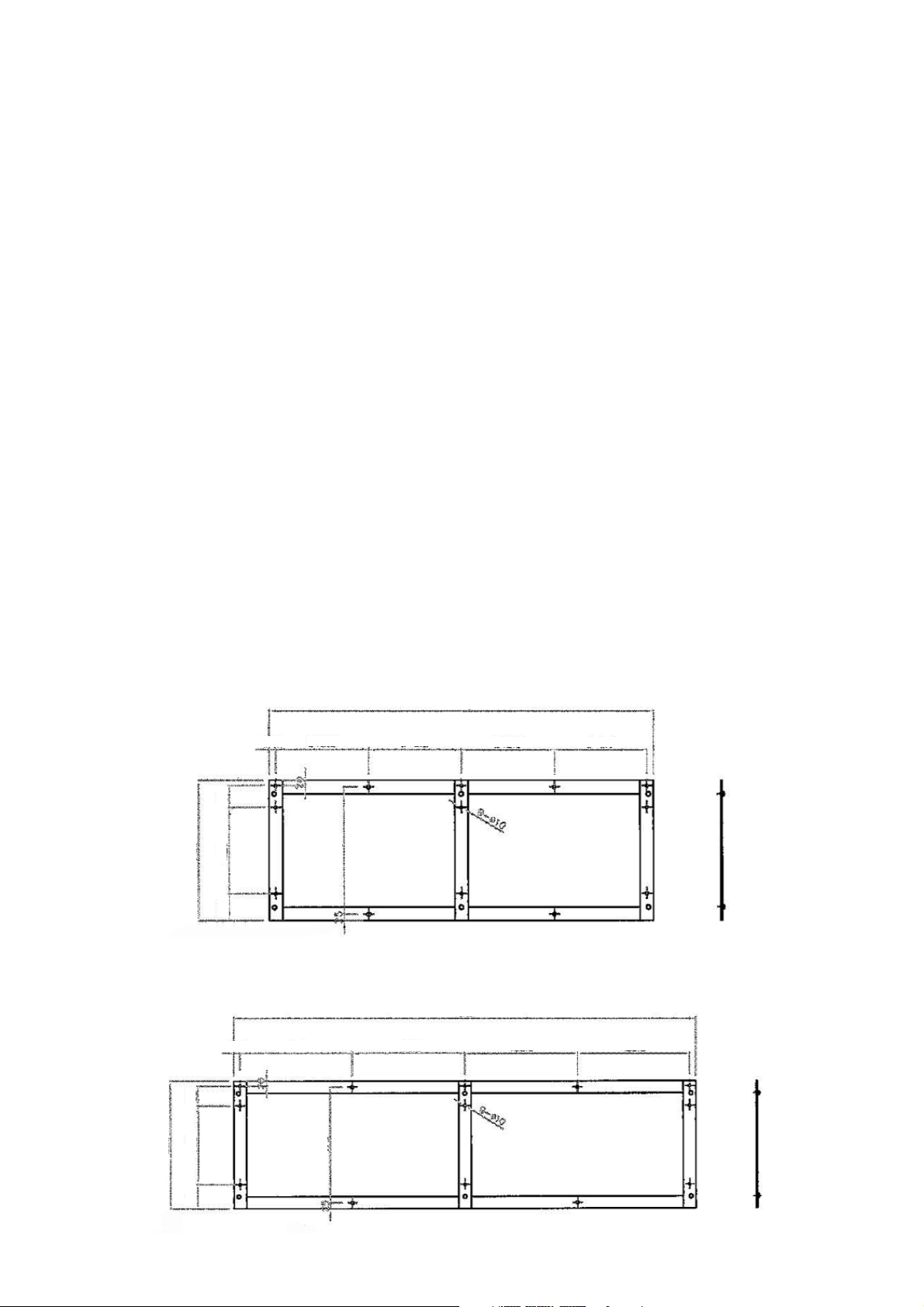
2. Place the bracket on the wall and mark the correct position of the holes by using a level. (See figure 1).
Attach the brackets securely to the wall. The wall mount bracket is shipped attached to the unit mounting
bracket on the rear of the unit.
Fixing Diagram for Coral - CWM14
1418mm
Figure 1
24.5mm
342.3mm
520mm
100
320
80
470
342.3mm
342.3mm 342.3mm
Fixing Diagram for Coral - CWM18
1883mm
24.5mm
458.5mm
520mm
100
320
80
470
458.5mm
458.5mm 458.5mm
Page 3
3. Carefully lift the unit onto the wall mounting bracket making sure the unit mounting bracket is securely in the
wall mount bracket.
4. Assure unit is level. Shimming may be required so unit is tilting at top or bottom.
5. Inspect the glass doors for proper opening and closing motion.
Mains Connection
The unit comes fitted with a moulded plug for safety and must
be earthed. If the mains connection cable/plug is damaged,
please contact the spares office on +44 (0)1553 817017 for a
replacement.
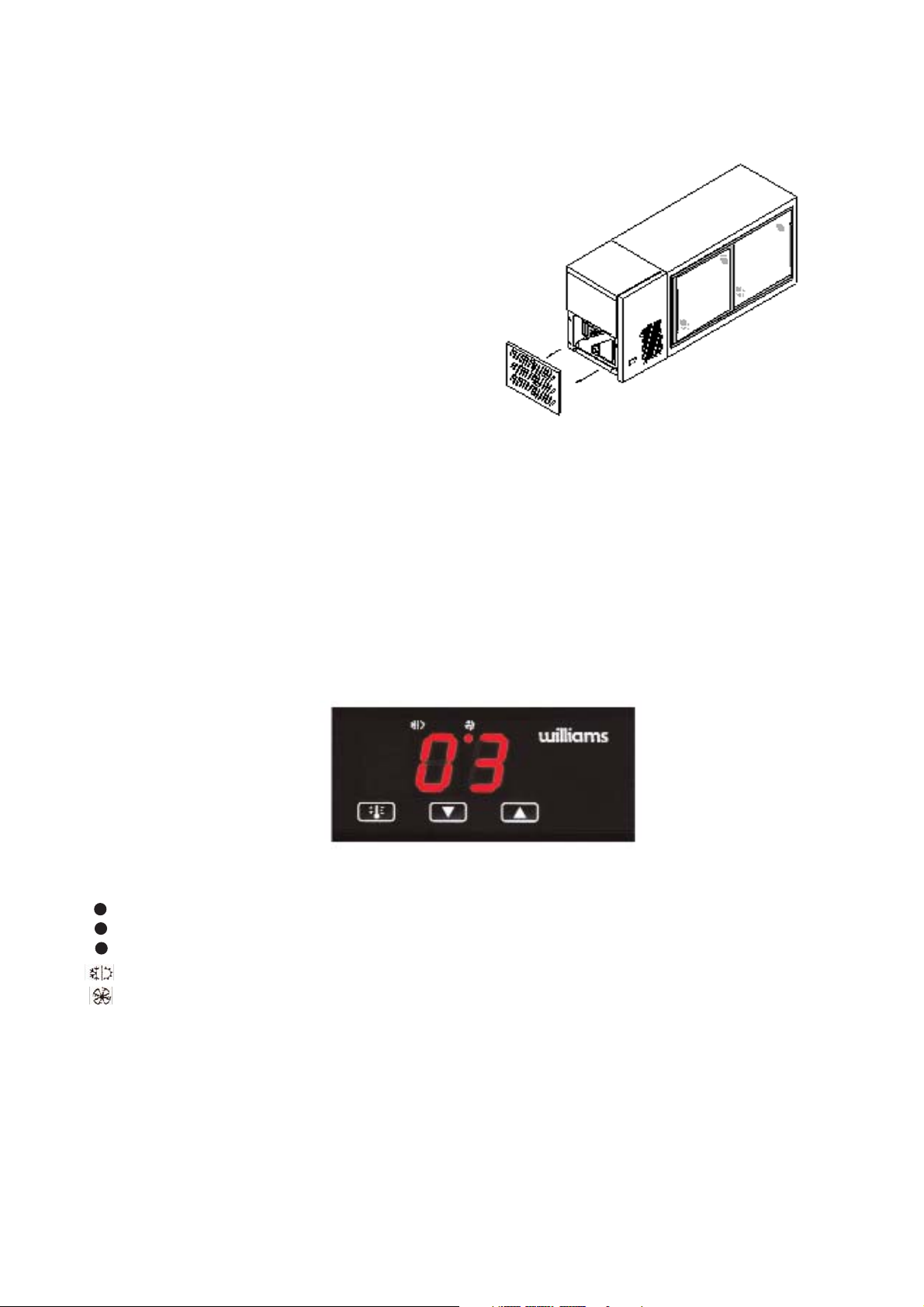
To access the mains connection plug, pull the louver on the left
hand side down from the unit. Take out the connector plug from
the housing unit and replace the louverback. (See figure 2).
Shelf Weight Distribution
Before loading, allow unit to reach normal operating temperature (+1°C to +4°C).
When loading the unit, please ensure that the load is equally distributed throughout and ensure air can circulate around
and through stored products. Ensure all items are covered and that raw and cooked foods are stored separately.
THERMOMETER
The controller is marked in Centigrade or Fahrenheit.
The Thermometer should be checked daily to ensure that correct temperature is being maintained.
Figure 2
CONTROL PANEL
LED Display
Normal cabinet temperature displayed in the LED window
Probe 1 (air) failure (E1)
Probe 2 (evaporator) failure (E2)
Initial Operation
Your cabinet is delivered ready to run. Plug into the mains and the cabinet is ready to use. ‘- -’ will appear in the
digital display and the temperature will then display. Wait until the cabinet has reached its normal operating
temperature (+1°C to +4°C) before loading it.
LED shows red to indicate unit running
LED illuminates red to indicate Evap running
Page 4
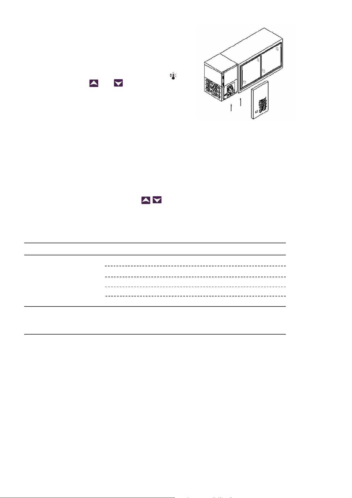
Locating the Controller
Grasp the unit cover and pull upwards aways from the unit.
(See figure 3).
Adjusting the Operating Temperature
NB: All machines are preset at the factory, however
conditions on site will vary compared with test conditions
and it may be necessary to perform the above adjustments
several times in order to obtain a perfect temperature cycle.
Probe Fail-Safe Feature
The controller features a fail-safe condition. In the event of a temperature probe failure, the compressor will alternate
at 5 minute intervals indefinitely between running and not running condition and E1 or E2 will be displayed. Normal
compressor function will only be restored when the probe fault has been repaired.
Defrost Operation
To instigate a manual defrost press and hold
ROUTINE MAINTENANCE
All maintenance should be carried out by a competent, qualified person. We recommend regular preventative
maintenance using a qualified service provider in order to get the best from your equipment.
CLEANING
Exterior: If cabinet exterior is looked after correctly it will retain an “as new” finish for many years. Normal day to
day cleaning should be carried out with a soft cloth and soapy water. For a stainless steel finish, always wipe
cabinet in same direction as the grain. Whilst stainless steel is robust, the satin smooth finish can be spoilt by wiping
against the grain. Never use abrasive materials or cleaners, or chemical cleaners. These can damage the surface
and cause corrosion. Occasionally, the exterior surface should be polished with a good stainless steel polish to
protect it.
To adjust the operating temperature press and hold the
key for 3 seconds. Use
and
keys to adjust.
Figure 3
buttons simultaneously.
Fault Diagnosis / Display Conditions
Fault/Display Possible Cause Action
Cabinet not Operating No Power Supply Check fuse or power source
Cabinet not maintaining 1. Dirty Condenser Clean
temperature
2. Air circulation restricted Remove Restriction
3. Defective Fan Motor Call engineer
4. Defective Compressor Relay Call engineer
5. Loose electrical connection Call engineer
Faults displayed by E1 or E2 - Control Probe Failure Call engineer
Control
hi or Lo - High/Low temperature alarm Call engineer
Page 5
Interior: Cabinet interior should be cleaned regularly with warm soapy water and a soft cloth. Dry thoroughly
afterwards and where possible remove all shelving to aid the process.
DOOR REMOVAL / INSTALL / ADJUSTMENT
Door Removal
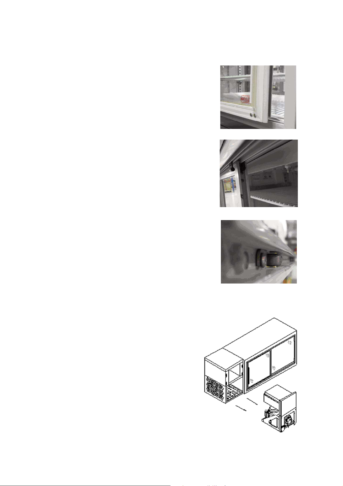
1. Locate outside door (sticker in lower corner of door - see figure 4)
2. Open door 3” and lift door up
3. Pull lower part of door out and away from the unit
4. Repeat process for inside door
Door Installation
1. Locate inside door
2. Place black spring closure tab at rear to top of door frame
(See figure 5)
3. Insert lower part of door into the track when door is 3” open
4. Assure door spring forces door closed
5. Repeat process for outside door
Door Adjustment
Roller bearings on the bottom of each door may be adjusted to allow for
proper seal of glass door. To look for proper door sealing assure that the
bumper gasket of each door touches the entire vertical side of the door frame.
No gaps should be visible. (See figure 6)
CONDENSER CLEANING
The condenser is part of the refrigeration unit and is located in
the unit compartment. It requires cleaning approximately 4
times per year. To clean, disconnect mains supply before
starting. Brush fins vertically with a stiff brush, taking care not
to damage them or push dirt/dust further in.
Take care not to damage any electrical connections and cables
during removing and the cleaning process. Replace unit cover
and plug cabinet in after completing cleaning process.
If there are further grease deposits still remaining on the
condenser call your Service provider to carry out a full service.
NOTE: Non-compliance may invalidate your Warranty.
To access the condenser, remove the unit panel, then grasp
bottom of unit compartment and lift slightly while pulling
forward. The refrigeration cassette will slide out provide
access to components. To replace cassette reverse procedure. (See figure 7)
Figure 4
Figure 5
Figure 6
Figure 7
Page 6

EVAPORATOR/DRAINLINE
Inspect periodically to ensure the drain hole is not blocked.
BREAKDOWN
In the event of a breakdown, please check thermostat setting and fuse before calling service engineer. When calling,
please advise model and serial number. This information can be found on the identification plate inside unit. It should
also be noted on the cover of this booklet. Please ensure that all redundant parts are disposed of safely and legally.
Page 7
WARRANTY POLICY - Effecttive from 1st March 2010
Warranty applies to equipment manufactured by Williams
Refrigeration and equipment bearing the Williams name plate and
serial number identification tag.
We undertake, in conjunction with the supplying agent, distributor or
representative, to repair free of charge any such piece of equipment or
part thereof used which is found to be faulty in either materials or
workmanship.
Products Covered
A 24 months Warranty from the original date of purchase is given to
the following Williams equipment:
Garnet / Sapphire / Zircon / Jade / Amber (stainless) /
Mobile Heated / Mobile Refrigerated.
Reach-in Blast Chillers / Reach-in Blast Chillers Freezers.
Opal / Emerald / Onyx / Aztra / Salad Counters.
Crystal Bakery Cabinets and Counters.
A 12 months Warranty from the original date of purchase is given to
all other Williams equipment including:
All Modular Products (including Coldrooms).
Remote Systems (including Glycol).
Bottle Coolers.
Multidecks.
GEM Product Range.
Bottle Well / Meat Freezer Well.
Thermowell.
White Goods.
Non Standard Products.
Warranty Terms
The equipment has been installed correctly and has not been subject
to misuse or abuse but is functioning correctly.
The equipment was purchased by the authorised supplying distributor
direct from Williams Refrigeration and not through a wholesales or
other supplier whose warranty may be different.
The Warranty Policy shall be non-transferable.
Replacement of defective equipment can only be made with the
approval of Williams Refrigeration.
Any repair under warranty will only be carried out in its position of
operation or in a suitable location on the customer’s premises. If the
product has to be removed for security or any other reason, this will be
subject to additional charge (may include hydrocarbon charged
equipment).
Warranty work will be covered by Williams Refrigeration or by one of
its appointed agents between the hours of 8.00am and 5.30pm
Monday to Friday.
Exceptions to Standard Warranties
Second hand equipment.
The Standard Warranty is for Mainland GB only (does not cover
Marine equipment).
Any third party item(s) connected to the equipment that may affect
performance.
Components inlcuding gaskets, doors / drawers, handles, shelves,
trayslides, all internal fixings, plug and lead, connectors, the outer
shell, castors / legs, food probes, refrigerant and blockages as well
as consumable items such as (but not limited to) batteries, fuses,
light bulbs, printer cartridges, keys, glass and paper roll.
Any fault not reported within 10 working days of being discovered.
No claim shall exceed the original selling price.
Where equipment is manufactured to the customers’ own design,
Williams Refrigeration will not be liable for any non performance or
operation of the equipment as a result of a design fault.
The customer permits persons other than those authorised by
Williams Refrigeration to perform or effect repairs or adjustments to
the equipment.
Repairs are made using spare parts or replacements not of the
same make as those supplied originally as components of the
equipment unless authorised by Williams Refrigeration.
If authorised representatives of Williams Refrigeration are denied full
and free rights of access to the equipment for inspection during
normal business hours as previously stated.
The customer has not properly maintained the equipment or carried
out annual servicing, including cleaning the condenser, in
accordance with instructions, literature or directions issued
by Williams Refrigeration. (Operating Instructions are supplied with
all equipment but also available at www.williams-refrigeration.com).
The customer fails to observe commonly accepted operating
practices.
The customer uses or installs the equipment in such a way that it
exceeds its design envelope.
Call out and repair costs if no fault found or access denied.
The initial supply date shall apply to a replacement.
Equipment fails through misuse, abuse, accidental damage, power
surges or spikes, fire, flooding or acts of God.
Food and / or contents or the product ( including pharmaceutical).
Claim Procedure
If a customer wishes to make a claim under the terms of this
warranty, the following procedure should be observed:
Contact the supplying agent, representative or distributor.
Quote the model, date of installation and serial number of the
cabinet. The serial number is located on the cabinet identification
plate inside the cabinet. It should also be recorded on the
operating instruction booklet supplied with the cabinet.
Note: contents risk and insurance responsibility remains at all times
with the customer.
A current list of main distributors is avilable on request.
Extended Warranty
Extended Warranty offers the opportunity to protect your equipment
(subject to conditions outlined) for an additional period of up to 5 years
inclusive of original warranty periods.
Should you require Extended Warranty, state on your order or notify
the Dealer or Williams Sales Manager at the time of purchase and they
will be able to arrange it for you.
To ensure your Extended Warranty Policy remains valid, at least one
maintenance / service visit per year must take place in years 2, 3, 4
and 5.
All - Inclusive Parts & Labour Warranty
An all inclusive 2 year Parts & Labour Warranty, subject to the
Warranty Policy terms, is available from your Williams Dealer. Contact
your delaer for further details.
This warranty does not affect your statutory rights.
March 2010
Page 8

WILLIAMS REFRIGERATION
Bryggen Road,
North Lynn Industrial Estate
King’s Lynn, Norfolk PE30 2HZ
Sales Tel: +44 1553 817000 Fax: +44 1553 817111
Spares Tel: +44 1553 817017 Fax: +44 1553 817020
Email: [email protected]
Website: www.williams-refrigeration.com
WILLIAMS SILVER FROST
30 Route d’Ahun
23150 Lavaveix Les Mines
France
Tel: +33 5 55 52 27 88 Fax: +33 5 55 62 10 61
Email: [email protected]
Website: www.williams-silverfrost.com
WILLIAMS REFRIGERATION AUSTRALIA
38-42 Gaine Road
Dandenong South, Victoria 3175
Australia
Tel: +61 3 8787 4747 Fax: +61 3 8787 4787
Email: [email protected]
Website: www.williamsref.com.au
WILLIAMS HONG KONG
4A Harrington Building,
36-50 Wang Wo Tsai Street, Tsuen Wan,
North Territories, Hong Kong
Tel: +852 2407 5422 Fax: +852 2407 3767
Email: [email protected]
Website: www.williams-hongkong.com
Coral O&M
Rev 3
March 2010
 Loading...