

N
W
G
W
G
W
G
W
G
W
G
W
G
Sealed Combustion Oil Furnaces
SCH High Boy
SCL Low Boy
KEEP THESE INSTRUCTIONS
WITH FURNACE FOR FUTURE
REFERENCE.
DANGER
ARNIN
ARNIN
ARNIN
CAUTION
ARNIN
Hazards that will cause severe personal injury,
death or substantial property damage.
Hazards that can cause severe personal injury,
death or substantial property damage.
INSTALLER – Read all instructions before
installing. Read page 2 first. Follow all instructions
in proper order to prevent personal injury or death.
• Consider ducting, fuel supply, venting and
installation when determining furnace location.
• Any claims for damage or shortage in shipment
must be filed immediately against the transportation
company by the consignee.
Do not store or use gasoline or other flammable
liquids or vapors near this furnace or any other
appliance.
Ventilate house while operating furnace for the first
time. Odors may be emitted for a brief period.
Do not alter this furnace in any way. The
manufacturer will not be liable for any damage
resulting from changes made in the field to the
furnace or its components or from improper
installation. Failure to comply could result in severe
personal injury, death or substantial property
damage.
Hazard definitions
Furnace Manual
Contents
Read this first!............................................................................2
1. Prepare furnace location............................................................ 3
2. Prepare furnace and place in position .......................................5
3. Connect supply and return ducts............................................... 6
4. Venting – Sealed Combustion System ......................................9
5. Connect fuel oil piping..............................................................15
6. Wire furnace and burner.......................................................... 16
7. Start-up.................................................................................... 18
8. Checkout procedure.................................................................19
9. Troubleshooting....................................................................... 21
10. Service and maintenance ........................................................22
11. Components and replacement parts........................................ 25
12. Dimensions and ratings ...........................................................34
13. Owner’s information ................................................................. 38
CAUTIO
NOTICE
Page
Hazards that will or can cause minor personal
injury or property damage.
Special instructions on installation, operation or
maintenance that are important but not related to
personal injury or property damage.
ARNIN
ARNIN
NOTICE
USER – Please read the following. Failure to
comply could result in severe personal injury, death
or substantial property damage.
• This manual is for use only by your qualified
heating installer / service technician.
• Please see the Owner’s information only, on back
page of this manual.
• Have the furnace serviced by a qualified service
technician, at least annually.
This manual must only be used by a qualified
heating installer / service technician. Furnace and
burner must be installed and serviced only by a
qualified heating installer / service technician.
Failure to comply could result in severe personal
injury, death or substantial property damage.
When calling or writing about the furnace, please
refer to furnace model number and serial number
shown on the rating label. You may list the serial
number and model number in the space provided on
the “Installation and service certificate” found on
page 20.
670-000-006-1007
W
G
READ THIS FIRST!
ARNIN
Service and maintenance
1. To avoid electric shock, disconnect electrical supply before
performing maintenance.
2. To avoid severe burns, allow furnace to cool before performing
maintenance.
3. Perform service and maintenance as described in this manual
and the burner manual.
4. Do not attempt to make adjustments to the blower or motor while
the furnace is in operation. Disconnect power to the furnace and
be sure all parts have stopped moving before attempting
adjustments or maintenance.
5. The burner must be set up and adjusted using combustion test
instruments. Visual examination of the flame alone cannot
determine combustion performance.
Operation
6. Do not use the furnace as a construction heater.
7. Do not operate any furnace if the heat exchanger is damaged,
corroded or pitted. Toxic flue products could enter the air
stream.
8. Do not jumper, attempt to by-pass or override any limit control.
9. Do not block flow of combustion or ventilation air to furnace. Do
not block or obstruct the air openings in the furnace casing.
10. Do not store or use combustible materials, gasoline, or other
flammable liquids or vapors in the furnace area.
11. Do not operate the furnace if the furnace area will be exposed to
air contaminants.
12. Should overheating occur, do not turn off or disconnect electrical
supply to furnace. Instead, shut off the oil supply at a location
external to the appliance, if possible.
13. Do not use this furnace if any part has been under water.
Immediately call a qualified service technician to inspect the
furnace and to replace any part of the furnace, control system or
burner that has been under water.
14. Do not operate furnace if temperature rise through heat
exchanger exceeds 85
NOTICE
Installation –
1. Be sure to level the furnace, using a spirit level on the front and
one side. If the furnace is not level, oil can drip into the
combustion chamber after burner cycling, causing fouling of the
heat exchanger and the burner head.
2. Make sure all legs are in contact with the floor to distribute the
load and prevent the possibility of undue noise or vibration.
Failure to adhere to the guidelines below can result in severe personal injury, death or substantial property damage.
o
F.
Apply the following suggestions to prevent unsatisfactory operation of the furnace.
15. Inspect, clean and replace (if necessary) return air filter
regularly.
16. Do not obstruct return air grills or supply air outlets.
17. Supply only #2 fuel oil to the burner. Never attempt to use
gasoline, a mixture of gasoline and oil, waste fuel, refuse or any
other substance in the burner of furnace.
Installation
18. Do not block flow of combustion or ventilation air to furnace. Do
not block or obstruct the air openings in the furnace casing.
19. Connect furnace only to a functional vent system in good
condition. Place the furnace so as to allow proper venting, with
the shortest possible venting and minimum number or elbows.
20. Always connect and seal a return air duct to the furnace unless
the furnace is located in a large space, such as an unpartitioned
basement. Route the return air duct to an adjacent room if no
return air manifold is used.
21. Install furnace maintaining minimum clearances for service and
separation from combustible surfaces described in this manual.
22. Install, start-up, service and maintain burner per instructions in
this manual and the burner manual.
23. Verify burner is properly inserted through the combustion
chamber opening.
24. Furnace must be installed so that burner and control system
components are protected from dripping, spraying water or rain
during operation or service.
25. If installing an air conditioning evaporator coil, install the coil
downstream of, or in parallel with, the furnace to prevent
condensation in the furnace heat exchanger. If the coil is in
parallel, provide means to prevent flow of chilled air into the
furnace, including an interlock to prevent simultaneous operation
of heating and air conditioning.
3. Avoid locating return grills in rooms that may contain undesirable
odors.
4. Never locate a return air grill closer than approximately 20 feet
from the furnace.
5. Locate the furnac e near the center of the supply and return duct
systems.
6. Always check the size of the ducts on a replacement installation,
particularly if adding air conditioning.
2 670-000-006-1007
W
G
SCH & SCL Oil Furnaces – Furnace Manual
1 Prepare furnace location
Pre-installation checklist
Verify code compliance
Local, state, and national codes, laws, regulations and
ordinances
NFPA-31, Installation of Oil-Burning Equipment
National Electrical Code
All local codes and/or regulations take precedence over the
instructions in this manual and should be followed accordingly.
NOTICE
SCH & SCL furnaces, their burners and controls have
met safe lighting and other performance criteria when
they underwent tests, specified in Underwriters
Laboratories Standard UL727.
Check location and furnace specifications
Furnace heating capacity
Space is large enough to provide required clearances
Verify the installation will meet the requirements of this manual:
Clearances (page 3)
Combustion/ventilation air openings (page 4)
Supply air duct (page 7)
Return air duct (page 7)
Vent system (page 9)
Fuel oil piping (page 15 plus burner manual)
Electrical connection (page 15)
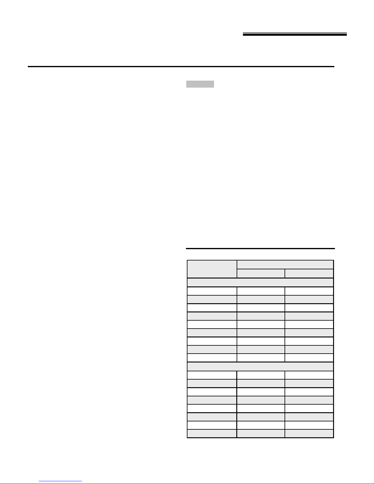
Clearances
Minimum clearances to combustible materials
1. Install the furnace, ductwork and vent such that no combustible
surface is closer than indicated in Table 1.
Table 1 Minimum clearances
Service accessibility clearances are
recommended minimum dimensions to
allow access to furnace components
(motor, blower, filters, etc.)
Side of furnace or supply plenum
Rear of furnace
Top of furnace casing or supply
plenum (warm-air duct within 6 ft. of
furnace)
Bottom of furnace
Front of furnace
Flue pipe
Minimum clearances from furnace, ductwork and vent
SCH-105 (3” vent dia.) SCH-160 (4” vent dia.) SCL-105 (3” vent dia.) SCL-160 (4” vent dia.)
To
combustible
construction
1"
For
service
accessibility
24"
(one side)
1" 24" 18" 24" 1" 24" 18" 24"
1" --- 2" --- 1" --- 2" --0" --- 0" --- 0" --- 0" ---
1" 24" 24" 24" 1" 24" 24" 24"
REFER TO SECTION 4 (VENTING)
NOTICE
Flue pipe clearances must take precedence over
jacket clearances (listed below).
Service accessibility clearances
1. Provide no less than the minimum clearances given in Table 1 to
ensure the furnace can be properly operated, serviced and
maintained.
2. Always apply whichever clearance is LARGER – combustible
construction or service accessibility.
Flooring and foundation
Flooring
SCH & SCL furnaces are approved for installation on combustible
flooring, but must never be installed on carpeting.
ARNIN
Do not install furnace on carpeting even if foundation
is used. Fire can result, causing severe personal
injury, death or substantial property damage.
Foundation
1. Provide a solid brick or minimum 2 inch thick concrete
foundation pad if any of the following is true:
• the floor can become flooded.
• the furnace mounting area is not level.
Residential garage installations
Take the following special precautions when installing the furnace in
a residential garage. Il the furnace is located in a residential garage:
• Mount the furnace a minimum of 18 inches above the floor
of the garage.
• Locate or protect the furnace so it cannot be damaged by a
moving vehicle.
To
combustible
construction
1"
For
service
accessibility
24"
(one side)
To
combustible
construction
1"
For
service
accessibility
24"
(one side)
To
combustible
construction
1"
For
service
accessibility
24"
(one side)
670-000-006-1007 3
3
N
W
G
SCH & SCL Oil Furnaces – Furnace Manual
1 Prepare furnace location (continued)
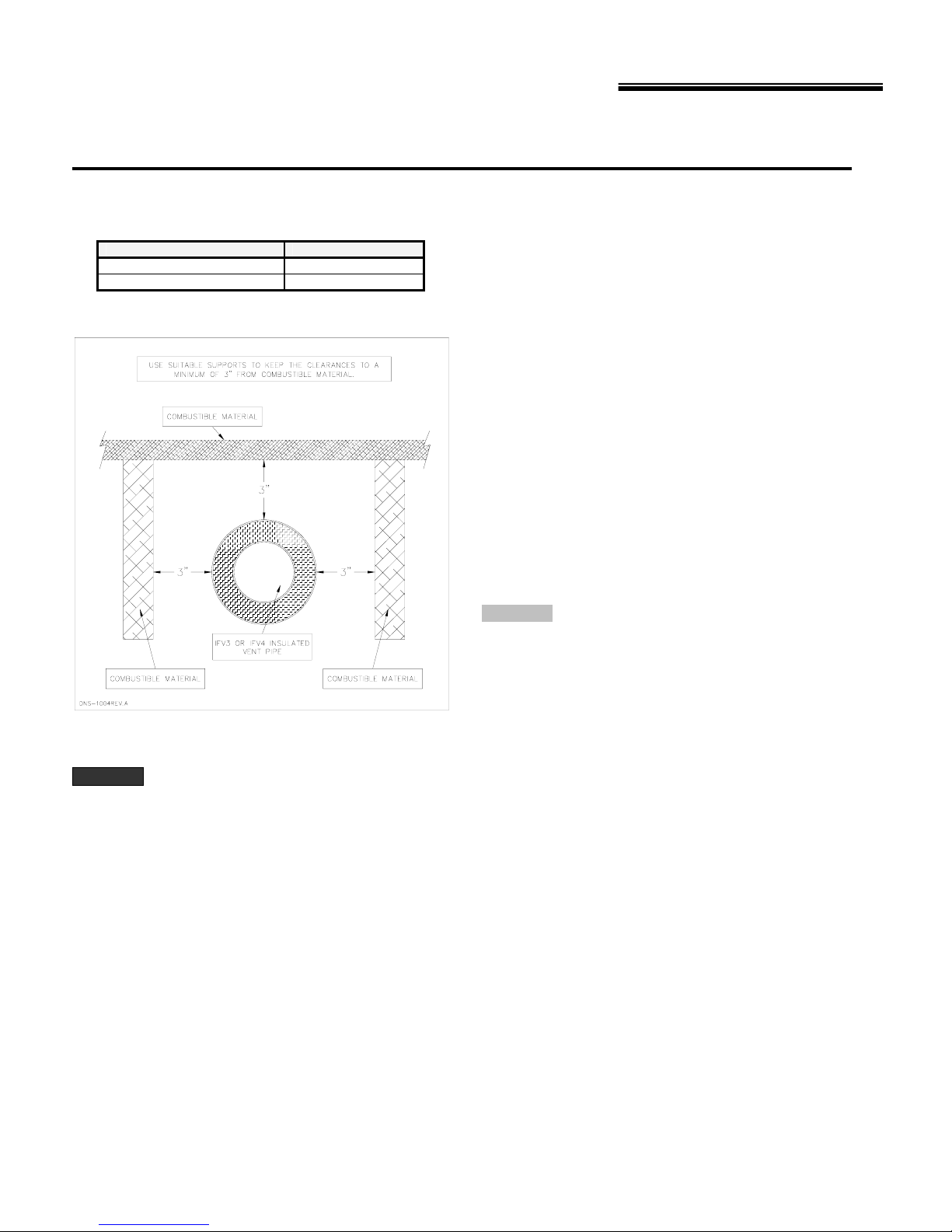
Vent pipe clearances
Table 2 Minimum clearances – side-wall venting
CLEARANCES
Vent pipe, up to vent terminal 3"
Vent terminal Zero
Figure 1
ARNIN
Do not enclose venting in a ceiling or combustible
structure.
Vent terminal location
Select a location for the vent terminal in accordance with all local
and national codes. The following requirements shall be considered
to be minimum requirements that can be overridden by stricter local
and national codes.
Following are excerpts from the NFPA 31 code:
The vent shall terminate at least 3 ft. above any air inlet to the
structure that is within 10 ft. of the termination point.
The combustion air inlet and flue gas outlet of a direct vent
appliance shall terminate at least 1 ft. (0.3 m) from the soffit of the
roof of the structure and at least 3 ft. (0.9 m) from an inside corner of
an L-shaped structure.
The vent terminal shall be located at least 1 ft. (0.3 m) from any
door, window or air inlet to the structure. The flue gas outlet terminal
shall also terminate at least 1 ft. (0.3 m) above grade.
The vent shall not be less than 7 ft. ( 2.1 m) above grade, when
located adjacent to public walkways.
The vent shall terminate at least 5 ft. (1.6 m) from the vent outlet of a
supply tank.
CAUTIO
Most codes have a notwithstanding clause which
states that, products of combustion shall not enter
the dwelling under any circumstances, even if all
other code requirements as to construction and
location have been complied with. The installer is
ultimately responsible to do whatever is necessary
to ensure that flue gases do not enter the dwelling.
4 670-000-006-1007

W
G
W
G
W
G
SCH & SCL Oil Furnaces – Furnace Manual
2 Prepare furnace and place in position
Inspect & prepare furnace
Remove furnace from carton
Remove the furnace from its shipping carton and inspect thoroughly.
Remove access panels to inspect the furnace interior.
NOTICE
ARNIN
Immediately file a claim with the transportation
company if you discover concealed damage.
Do not install or attempt to operate the furnace if the
heat exchanger, burner or controls have been
damaged. Immediately contact your furnace
supplier. Operating a damaged furnace could result
in severe personal injury, death or substantial
property damage.
Prepare furnace (SCH models)
SCH furnaces require cutting the return air opening into one side of
the furnace. Carefully cut the opening on the correct side of the
furnace, using the four knock-outs on the side as guides.
Prepare burner
Remove the burner from its shipping carton and inspect thoroughly.
Read the burner manual and follow instructions for preparing and
installing the burner.
Install the correct nozzle for the required firing rate, using the burner
manual and the information in Section 12 of this manual. Follow the
burner manual instructions for nozzle installation. Verify the correct
setting of electrodes after nozzle and burner oil tube assembly are in
place.
Openings in walls, floor & ceiling
General
Ensure that the finished door opening to the furnace room is large
enough to install and remove the furnace, water heater or any other
appliances in the room.
Before placing furnace in a closet or small room, cut all openings
required in floor, ceiling or walls for ducts and vent. This will simplify
the work and prevent construction dust from entering the furnace
heat exchanger.
ARNIN
Duct locations and sizing
Verify the size of the supply and return duct system is sufficient for
the application. The pressure drop through the duct system must not
exceed 0.25 inch water column. The total drop through the duct
system and air conditioning evaporator coil (if used) must not
exceed 0.5 inch water column.
Verify that all clearances to combustible construction
and as needed for service accessibility will be met.
The vent must be no closer than 3 inches to any
combustible surface. Failure to comply could result
in severe personal injury, death or substantial
property damage.
Openings in walls, floor… (continued)
See suggested duct sizing in this manual. For more detailed sizing
information refer to ACCA Manual D.
Return air duct
You must install a return air duct, sealed to the furnace, even if no
return manifold is used. The only exception is when the furnace is
located in a large unpartitioned room, such as a basement. (A room
whose volume is at least 50 cubic feet per 1,000 BTU/h input of all
appliances in the room is considered large). For large rooms, return
air may be taken directly at the furnace, without a return air duct. No
return air register should be within 20 feet of the furnace.
Cut the required opening for the return air duct in the wall (or floor or
ceiling) of the room before placing the furnace.
Install filter
Install return air filter of the size listed in Section 12.
You will need to install a filter rack provided with the furnace for
Model SCH only.
NOTICE
Verify that the filter will be easily accessible for
removal after the furnace is in place.
Install furnace and burner
Place furnace
Place the furnace in the desired location. Measure clearances and
verify per page 3 of this manual.
Using a spirit level on the front and one side of the furnace, level it
using the 4 or 6 levelling legs. Make sure each of the legs is firmly in
contact with the floor.
Inspect combustion chamber
Inspect the combustion chamber. Verify it is in good condition and
correctly in position inside the heat exchanger. The burner opening
in the chamber must align with the burner heat exchanger opening.
ARNIN
Insert burner
Following the burner manual instructions, install the burner and its
gasket in the burner opening. Make sure the burner is aligned with
the opening in the combustion chamber and that burner insertion
corresponds to the value specified in Section 12.
Secure the burner in place with the three nuts and washers
provided. Wire and pipe fuel to the burner per burner manual and
this manual.
Burner orientation
Always keep the motor shaft in a horizontal position
The combustion chamber is constructed of ceramic
fiber materials See the WARNING information on
page 23 of this manual. Comply with these
instructions when handling any ceramic fiber or
fiberglass materials. Failure to adhere to these
guidelines could result in severe personal injury or
death.
670-000-006-1007
5
N
SCH & SCL Oil Furnaces – Furnace Manual
3 Connect supply and return ducts
Duct sizing
Determine air flow CFM
The temperature rise through the furnace must not exceed 85o F and
should be at least 55°F for comfort. When calculating air flow,
assume a temperature rise of 70°F.
The sensible heat temperature change for cooling would be
approximately 27-30°F. Actual temperature change will be
approximately 18-21°F due to humidity of the air.
To calculate the sensible heat temperature change (ΔT), you can
use the formula:
ΔT = BTU/h/(1.1 x CFM) Eq. 3-1
To calculate air flow when you know temperature change (ΔT), you
can use:
CFM = BTU/h/(1.1 x ΔT) Eq. 3-2
You can estimate air flow using the following rules of thumb:
Heating: 14 CFM per 1,000 BTU/h output Eq. 3-3
Cooling: 400 CFM per ton air conditioning Eq. 3-4
Determine the required air flow based on whichever is larger –
heating mode or air conditioning mode.
Examples:
1. What would the temperature rise be for a 100,000 BTU/h output
furnace with an air flow rate of 1200 CFM?
Use Equation 3-1 since you know CFM and BTU/h:
ΔT = 100,000/(1.1 x 1200) = 76°F
• The temperature rise would be 76°F.
• If the air enters the furnace at 70°F, it would leave the
furnace at 70°F + 76°F = 146°F.
2. What would the air flow be to obtain a 70°F rise through a
120,000 BTU/h output furnace?
Use equation 3-2 since you know ΔT and BTU/h:
CFM = 120,000/(1.1 x 70) = 1,558 CFM
• The air flow would have to be 1,558 CFM to obtain a
temperature rise of 70°F.
3. Estimate the required air flo w for a 75,000 BTU/h output fu rnace
installed with a 2-ton air conditioning evaporator coil.
Heating mode air flow (use Equation 3-3):
CFM = 75 x 14 = 1,050 CFM
Cooling mode air flow (use Equation 3-4):
CFM = 2 x 400 = 800 CFM
• The larger number is 1,050 CFM (heating), so the duct
system should be sized for 1,050 CFM.
• The supply duct would need to be 16" round or a rectangular
equivalent such as 8" x 25" or 12" x 16", using Table 4, page
7.
4. Estimate the required air flow for the same furnace installed with
a 4-ton air conditioning evaporator coil.
Heating mode air flow is still 1,050 CFM.
Cooling mode air flow (use Equation 3-4):
CFM = 4 x 400 = 1,600 CFM
• The larger number is 1,600 CFM (cooling), so the duct
system should be sized for 1,600 CFM.
• The supply duct would need to be 18" round or a rectangular
equivalent such as 8" x 36" or 12" x 21", using Table 4, page
7.
6 670-000-006-1007
CAUTIO
Always check the size of existing ducts, particularly
if you are adding air conditioning. The air pressure
loss through the cooling evaporator coil reduces
available air flow. If the ducts are too small as well,
the system may not work satisfactorily on either
heating or cooling.
Determine duct dimensions
Table 4, page 7 and Table 5, page 8, provide typical round and
rectangular duct sizes for rectangular and flat oval galvanized ducts.
Do not apply these tables to size ductwork if the total equivalent
length of the duct exceeds approximately 100 feet. For longer
systems or for duct board, fiberglass-lined or flexible duct sizing, use
the ACCA Manual D or the ACCA duct sizing slide rule. These
tables are based on pressure loss of approximately 0.10 inch water
column per 100 feet equivalent length of duct.
Use Table 3 below to size or check sizing of take-offs to supply
registers or return grills.
Verify the size and type of registers, diffusers and grills from the
manufacturer’s ratings. Do not exceed the recommended flow rate.
The pressure drop allowance for each should not exceed
approximately 0.05 inch water column.
Install a return air filter, sized per specifications in Section 12.
Use only a return air filter mounted to the furnace. Do not add
additional filters unless the duct system is carefully sized to allow for
the additional pressure drop.
Table 3 Suggested maximum flow to runouts
TAKE-OFF SIZE
(Inches)
Sheet metal or ductboard
5 Round 60 45
6 Round 100 75
7 Round 140 110
8 Round 210 160
3 ¼ x 8 Stack 70 55
3 ¼ x 10 Stack 100 75
3 ¼ x 14 Stack 140 110
2 ¼ x 12 Stack 70 55
2 ¼ x 14 Stack 90 70
Flexible duct (keep bends to minimum)
6 Round 55 40
8 Round 120 90
10 Round 200 160
12 Round 320 250
14 Round 480 375
16 Round 660 530
18 Round 880 680
20 Round 1200 900
SUPPLY RETURN
CFM
W
G
SCH & SCL Oil Furnaces – Furnace Manual
3 Connect supply and return ducts (continued)
Duct sizing (continued)
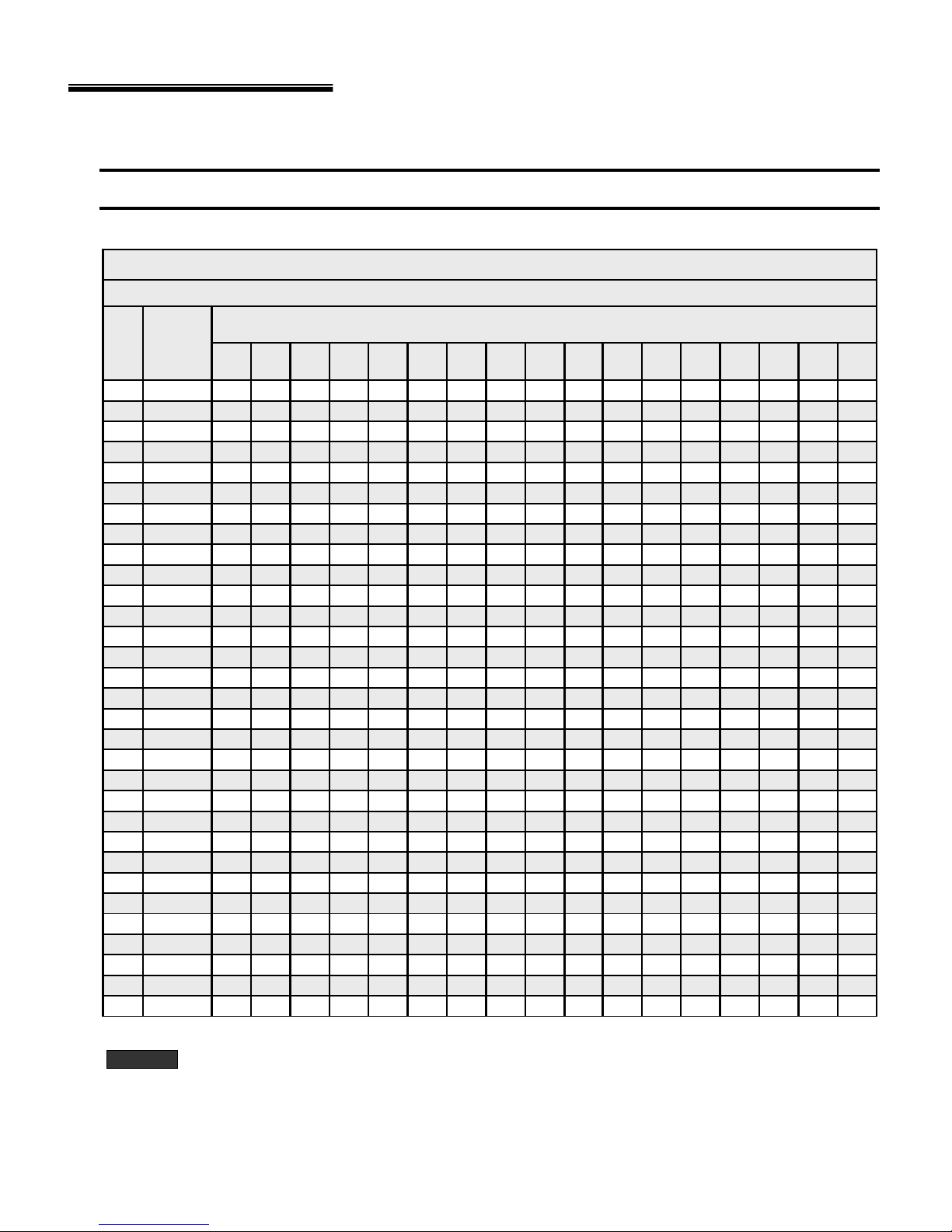
Table 4 Typical duct sizing for systems not over 100 feet equivalent length – round or rectangular galvanized
CFM
(For approximately 0.10 inch w.c. in a typical residential installation of galvanized metal duct)
Round
duct
diameter4567891012141618202224262830
(inches)xxxxxxxxxxxxxxxxx
45
65
100
150
200
250
300
400
500
600
700
800
900
1000
1100
1200
1300
1400
1500
1600
1700
1800
1900
2000
2200
2400
2600
2800
3000
3500
4000
ARNIN
Rectangular duct equival ent si zes
Mini mum width
4
5
6
7
8
9
9
10
12
12
12
14
14
16
16
16
16
18
18
18
18
18
20
20
20
22
22
22
22
24
26
444-------------6544-- - - --- - -----
865544-- - -- -----1297655544- -- ----141198766544- - ----181310987665544----20 15 12 10 9 8 7 6 6 5 5 4 4 - - - 2619151311109876655544322318151312119876665555
3828221815131210987766655
46322520171514111098777666
523628231917151311109887766
5841312521191714121110988777
6445342823201815131110998877
72493830252219161412111099887
-5441332724211715131211109988
- 58443529252218161412111010 9 9 8
- 6347383127241916141312111010 9 9
- 685140342925201715141212111010 9
- 725443363027211816141312111110 9
- - 58 45 38 32 28 23 19 17 15 14 13 12 11 10 10
- - 61 48 40 34 29 24 20 17 16 14 13 12 11 11 10
- - 64 51 42 35 31 25 21 18 16 15 14 13 12 11 11
- - 68 53 44 37 32 26 22 19 17 15 14 13 12 12 11
- - - 59 48 41 35 28 23 20 18 16 15 14 13 12 12
- - - 64 52 44 38 30 25 22 19 17 16 15 14 13 12
- - - 69 56 47 41 32 27 23 21 19 17 16 15 14 13
----61514434292522201817151514
----65544737302623211917161514
-----635442342926232119181716
-----726147393329262321201918
Do not apply this table for duct systems over approximately 100 equivalent feet length. For longer systems or systems using
other duct materials, refer to ACCA Manual D. Incorrectly sizing duct systems can result in unsafe or uncomfortable
operation.
(inches)
Typical duct sizing
for duct height s
(inches)
of :
670-000-006-1007
7
W
G
SCH & SCL Oil Furnaces – Furnace Manual
3 Connect supply and return ducts (continued)
Duct sizing
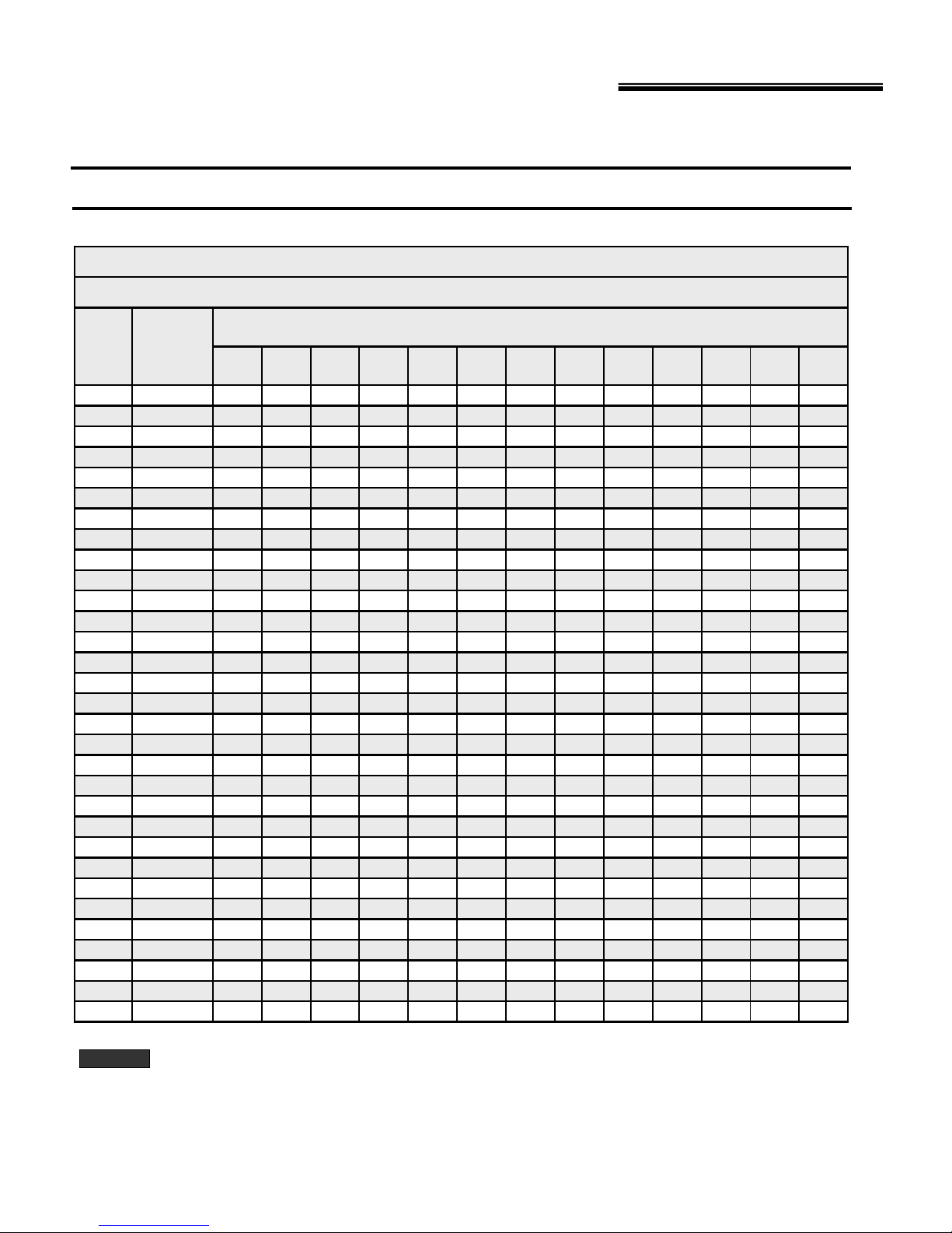
Table 5 Typical duct sizing for systems not over 100 feet equivalent length – round or flat oval galvanized
CFM
45
65
100
150
200
250
300
400
500
600
700
800
900
1000
1100
1200
1300
1400
1500
1600
1700
1800
1900
2000
2200
2400
2600
2800
3000
3500
4000
ARNIN
(continued)
Typical duct sizing
(For approximately 0.10 inch w.c. in a typical r esidential i nstallation of galvanized metal duct)
Round
duct
diameter3456789101214161820
(inches)xxxxxxxxxxxxx
10
12
12
12
14
14
16
16
16
16
18
18
18
18
18
20
20
20
22
22
22
22
24
26
Do not apply this table for duct systems over approximately 100 equivalent feet length. For longer systems or systems using
other duct materials, refer to ACCA Manual D. Incorrectly sizing duct systems can result in unsafe or uncomfortable
operation.
Flat oval duct equi val ent si zes
Mini mum width
4
5
6
7
8
9
9
65-----------
86----------1187---------161198--------211511108-------26181411109------302016131110------40262016141211-----4932241916141312----5938282219161513----694432252118161513----
-5036292420181614----
-5641322622201815----
- 634535292422191715 - - -
- 694938312623211816 - - -
- 755341332825221917 - - -
- - 58 44 36 30 26 24 20 18 - - -
- - 62 47 38 32 28 25 21 18 17 - -
- - 66 50 41 34 30 26 22 19 18 - -
- - 71 54 43 36 31 28 23 20 18 - -
- - - 57 46 38 33 29 24 21 19 - -
- - - 60 48 40 35 31 25 22 20 - -
- - - 63 50 42 36 32 26 23 21 19 -
- - - 67 53 44 38 33 27 24 21 20 -
- - - 73 58 48 41 36 29 25 23 21 -
----635244393227242221
----685648423429252322
-----6051443630272423
-----6454473832282624
------63544336322826
------71614840353129
(inches)
for duct heights
(inches)
of :
8 670-000-006-1007

W
G
W
G
W
G
SCH & SCL Oil Furnaces – Furnace Manual
4 Venting – Sealed Combustion System
ARNIN
Failure to follow all instructions can result in flue gas
spillage and carbon monoxide emissions, causing
severe personal injury or death.
The furnace can be side-wall vented without the use of a side-wall
power vent, using a venting system with the high static pressure
Beckett AFII and Riello 40-BF oil burners. Outdoor combustion air
must be directly connected to the burner or the venting system will
not function..
The notable characteristics of the vent system are as follows:
a) Certified for use of the following materials for ducting the intake
air from the terminal to the burner: Schedule 40 PCV DWV,
Schedule 40 ABS DWV and ASTM D-2729 sewer pipe;
b) One hole of minimal size (6 inches) is required to be cut into
the side-wall and the terminal is designed to fit through a
minimum 2 x 8 joist space.
c) Incorporates a vent blockage safety shutdown system. If the
vent or intake opening ever becomes partially or fully blocked,
the burner will shut down before a #1 smoke condition occurs;
d) The intake vent circuits within the terminal can be accessed for
cleaning.
There are three main components to the venting system:
- Vent terminal kit VTK-1 for the 105 series models or VTK-2 for the
160 series models.
- Flexible insulated venting material for IFV3 for the 105 series
models or IFV4 for the 160 series models
- Field supplied 3 inch PVC or ABS intake piping.
ARNIN
Poisonous carbon monoxide gas hazard.
Even though the flexible venting is insulated, it must
not run through an unheated space.
To do so can cause residual condensation inside the
stainless steel liner, which may eventually perforate
the liner and allow vent gases to enter the dwelling,
which can result in personal injury and/or death or
property damage.
Insulated flexible venting
The certified venting materials come in 3 lengths, Model # IFV3-15,
IFV3-23 and IFV3-30 for the 105 model series or IFV4-15, IFV4-23
and IFV4-30 for the 160 model series, correspond to 15, 23 and 30
feet of continuous lengths of vent. The vent construction is coaxial
and incorporates a stainless steel corrugated, flexible liner,
surrounded by a thick insulation blanket and covered with an outer
layer of flexible corrugated aluminum sleeve to protect the insulation.
Splicing vent lengths together is prohibited. The maximum and
minimum continuous vent lengths permitted for installation are:
5 feet minimum 30 feet maximum
Side-wall venting installation
ARNIN
Cut and abrasion hazard.
Always wear protective gloves and eye protection
when handling the vent material.
The process of cutting and fitting the flexible vent
material exposes the installer to sharp edges that can
cause severe cuts to the skin.
670-000-006-1007
Connection to the furnace breach
1. Determine in which direction the venting will be routed from the
furnace;
2. The flexible venting has 4 pieces of corrugated spi n sleeve that
has been temporarily screwed over top of it. Remove the spin
sleeve completely by unscrewing it in a counter-clockwise
direction;
3. Using tin snips, cut the aluminium outer sleeve back by 5
inches on the IFV Series vent (see Figure 1.1). Ensure the
snips are well adjusted and sharp or the cut end of the venting
will be too jagged to start the threads of the spin sleeve (see
Figure 1.1).
4. Prepare the furnace breach end of the insulated flex vent by
first screwing the spin sleeve onto the corrugated aluminum
jacket (see Figure 1.2) until the trailing edge of the spin sleeve
is about 12 inches from the end of the vent (see Figure 1.3).
5. Pull the insulation back to expose the corrugated stainless steel
core.
6. Cut the corrugat ed stainless steel core back by 3 inches on the
IFV Series vent. You should now have about 3 inches of
insulation hanging out past the stainless steel core (see Figure
1.4);
7. Push the stainless steel core onto the breach pipe as far as it
will go (see Figure 1.5) and mechanically attach the vent to the
breach using three of the #8 x 1/2" self-drilling screws provided
with the VTK Series kit. The screws should be equally spaced
around the circumference of the stainless steel core, starting
with the first screw at top dead center. Start the drill point of the
screws in the valleys of the corrugations at 3/8"-5/8" back from
the end of the stainless steel core, so the screw heads can be
properly sealed in the forthcoming operations (see Figure 1.6);
8. With the stainless steel core now firmly attached to the breach,
apply sealant all around the joint, where the corrugated
stainless steel core meets the smooth outer surface of the
breach pipe (see Figure 1.7). In other words, the sealant must
be centered over the joint;
9. Also, make sure that the heads of the self-drilling, stainless
steel screws are completely covered with the sealant;
10. Two stainless steel band clamps are provided with the VTK
Series kits. Position one stainless steel band clamp over the
sealant, so that the edge of the clamp closest to the breach
lines up with the sealant that is closest to the breach. Ensure
that the band will close with an action of one strip sliding over
the other - not under the gear head of the draw clamp (see
Figure 1.8). Tighten the band clamp with considerable torque to
cause the sealant to be squeezed into all crevices and to ooze
out of the edge of the clamp closest to the breach (see Figure
1.9);
11. The seal is permanent and should never need to be broken,
since the breach plate can be removed for cleaning and
inspection using the 4-bolt joint;
12. Tuck the vent insulation into the breach collar;
13. Screw the spin sleeve tightly into the breach collar for a finished
appearance. Wrap the other end of the spin sleeve with
aluminum tape to cover any metal burrs that may be present
(see Figure 1.10);
14. Bend the venting into the desired radius coming off the breach.
9

N
SCH & SCL Oil Furnaces – Furnace Manual
4 Venting – Sealed Combustion System (continued)
Connection to the vent terminal
1. Prepare the terminal end of the insulated flex vent b y first
screwing the spin sleeve onto the corrugated aluminum
jacket until the trailing edge of the spin sleeve is about 10
inches from the end of the vent;
2. Using sharp tin snips, cut the aluminum outer sleeve back
by 5 inches on the IFV Series vent;
3. Pull the insulation back to expose the corrugated stainless
steel core;
4. Cut the corrugated stainless steel core back by 3 inches on
the IFV Series vent. You should now have about 3 inches of
insulation hanging out past the stainless steel core;
5. Push the stainless steel core onto the pipe on the back of
the terminal as far as it will go and mechanically attach the
vent to the terminal using three of the #8 x 1/2" self-drilling
screws provided with the VTK Series kit. The screws should
be equally spaced around the circumference of the stainless
steel core, starting with the first screw at top dead center.
Start the drill point of the screws in the valleys of the
corrugations at 3/8"-5/8" back from the end of the stainless
steel core;
6. With the stainless steel core now firmly attached to the
terminal, apply sealant all around the joint where the
corrugated stainless steel core meets the smooth outer
surface of the breach pipe (see Figure 1.7). In other words,
the sealant must be centered over the joint;
7. Also, make sure that the heads of the self-drilling, stainless
steel screws are completely covered with the sealant;
8. Position the other stainless steel band clamp over the
sealant so that the edge of the clamp closest to the terminal
lines up with the edge of the sealant that is closest to the
terminal. Tighten the band clamp with considerable torque to
cause the sealant to be squeezed into all crevices and to
ooze out of the end of the clamp closest to the terminal (see
Figure 1.11);
9. The seal is permanent and should never need to be
disconnected as the end of the terminal can be opened for
cleaning and inspection by removing the screened end-cone
assembly. Tuck the vent insulation into the recess in the
terminal body;
10. Screw the spin sleeve tightly into the recess for a finished
appearance. Wrap the other end of the spin sleeve with
aluminum tape to cover any metal burrs that may be present
(see Figure 1.12);
11. Bend the venting into the desired radius coming off the
terminal.
Installing terminal in the wall
1. Cut a 6 inch hole in the side-wall in accordance with the
location considerations outlined in the previous section;
2. Fasten the wall plate to the inside-wall using 4 field-provided
fasteners, appropriate for the material behind the wall plate.
Depending on the angle of access, the pressure control
bracket may need to be removed to access the top right wall
plate screw hole. For concrete and block, Tapcon™ screws
or equivalent are recommended. Install the wall plate so that
the top of the hole in the wall plate is positioned 1/8” lower
than the top of the 6 inch hole in the wall. This will
accommodate the proper downward slope of the terminal, in
the direction from the inside to the outside;
10 670-000-006-1007
3. Remove the 2 screws fastening the end cone in place and
remove the cone;
4. Remove the 2 screws fastening the stabilizer shroud in
place and remove the stabilizer shroud;
5. Insert the main body of the terminal through the wall plate so
that the end of the terminal extends about 2 inches past the
outside wall;
6. Install the stabilizer shroud and replace the two mounting
screws. (see Figure 1.13);
7. On concrete and block wall installations in particular, if it
appears that the flange on the back of the stabilizer shroud
is not large enough to cover the irregularities in the hole, a
field fabricated wall plate can be constructed out of 304,
316, or 316L stainless steel;
8. Silicone seal the circumference of the joint where the
stabilizer shroud connects to the main body of the terminal;
9. Apply caulking to the back plate of the stabilizer shroud and
push the terminal back firmly against the wall, making sure
the pressure switch is located at the top, in a horizontal
position;
10. While pushing down gently on the top of the stabiliser
shroud, install the 3 stainless steel 2 inches screws provided
with the kit to secure the back of the shroud to the wall. Do
not overtighten the screws or it will distort the stabiliser
shroud. The screws will not be necessary in a concrete or
block wall as the mortar can provide positive positioning;
11. Tighten the clamp on the wall plate to secure the terminal in
place;
12. Apply more caulking all around the seam where the
stabilizer shroud meets the wall. It is important to have a
good seal to prevent water from entering the dwelling (see
Figure 1.14). A considerable amount of caulking may be
necessary for irregular wall surfaces such as lapped siding;
13. Install the end cone and replace the two mounting screws;
14. Support the vent and intake air piping so that a 1/4" to 1/2"
downward slope (toward the outside) results for proper
drainage out the terminal body.
Ducted outdoor combustion air (Sealed Combustion System)
The burners are set up to duct outside combustion air directly to
the burner: the Beckett AFII and the Riello 40-BF for side-wall
venting.
CAUTIO
The venting system is a sealed system and completely isolates
the furnace from the interior of the building. The burner is totally
unaffected by any pressure fluctuations within the building
makes it ideal for tight home construction.
The use of ducted outside combustion air is
mandatory with side-wall venting systems. The
system operates on a balanced flue principle
and will not function properly if the combustion
piping is not attached and sealed at all
connections between the vent terminal and
burner inlet.
which

SCH & SCL Oil Furnaces – Furnace Manual
4 Venting – Sealed Combustion System (continued)
The venting system requires additional parts, which are not included
with the kit. These parts must be constructed of 3 inch Schedule 40
PVC, PVC-SWV, 26-SDR, SDSR-21, Septic Sewer Pipe or ABS
plastic pipe, fittings and sealant. Also, installation procedures, piping
and fittings must conform to the following ANSI/ASTM standards:
PVC ASTM D-1785
SDR-26, SDR-21 ASTM D-2241
Septic Sewer Pipe ASTM D-2729
PVC-DWV ASTM D-2665
PVC Primer and Solvent Cement ASTM D-2564
ABS Pipe and Fittings ASTM D-2235
Procedure for Cementing Joints ASTM D-2855
Additional parts required (not included in VTK kit)
a. 3 inch elbow fitting as required;
b. 3 inch plastic pipe;
c. 3 inch 90° elbow, female-female (for terminal);
d. 3 inch female to 2 inch female reducer (Riello 40-BF burner
only);
e. 2 inch 90° elbow, street t ype, female-male (Riello 40-BF burner
only);
f. 3 inch female-female PVC or ABS coupling, not sewer pipe
(Beckett AFII burner only);
g. Transition bushings to go from PVC or ABS to ASTMD-2279
Septic Sewer Pipe (if applicable).
If PVC fittings are mixed with ABS fittings, use solvent cement that is
approved for bonding the two plastics.
Intake pipe length
The venting system has been certified for 120 equivalent feet o f 3
inch intake pipe. Count a 90° elbow as 10 equivalent feet and a 45°
elbow as 5 equivalent feet in the calculation.
For example:
1 length of 5 feet = 5 equivalent feet
2 lengths of 10 feet = 20 equivalent feet
3 elbows, 90° = 30 equivalent feet
2 elbows, 45° = 10 equivalent feet
1 elbow, 90° (terminal) = 10 equivalent feet
1 elbow, 90° (Riello burner)
Total: = 85 equivalent feet, which is less
than 120 feet and therefore acceptable.
Intake pipe installation
Obtain the necessary additional parts, to complete the installation
and start by piping at the burner. If the optional vestibule was
installed, remove the appropriate knockouts in the side panels of the
vestibule. The lower 5 inch knock outs in the right-hand panel is
used for the Beckett AFII burner. The higher 5 inch knockouts on the
right and left-hand panels are for right or left connection to the Riello
40-BF burner.
= 10 equivalent feet
Beckett AFII burner
Remove the burner intake cover by removing 3 screws securing it in
place. Discard the cover and screws. Apply silicone liberally around
the end of a 3 inch coupling and fully insert the siliconed end into the
burner opening. Fasten securely with 3 self-tapping sheet metal
screws.
Riello 40-BF burner
Fully insert the female end of the 2 inch, 90° street elbow into the
combustion air fitting on top of the burner. Fasten securely with 3
self-tapping sheet metal screws. Cement the 2 inch end of the 3 inch
female to 2 inch female reducer into the male end if the 2 inch 90°
street elbow. If the parts are not easily obtained, use a 3 inch 90°
street elbow with the male end fitted over the combustion air fitting.
The fitting will have to be silicone sealed, as the fit will be a bit loose.
Fasten securely with 3 self-tapping sheet metal screws.
Terminal connection
Insert the 3 inch 90° female-female elbow onto the stainless steel air
intake fitting located on the right side of the vent terminal (viewed
from the rear). Fasten with 3 self-tapping sheet metal screws.
Intermediate piping
Pipe as required between the terminal and the burner. Ensure that
the 3 inch piping is routed and supported in accordance with local
and national codes. Obey minimum furnace clearances to
combustibles when routing any section of 3 inch piping in the vicinity
of the furnace. If Septic Sewer Pipe is to be used, install transition
bushings at the 3 inch female ends of the fittings at the burner and at
the terminal. Transition bushings are readily available and are
required because 3 inch PVC and ABS pipes have a typical outside
diameter of 3.5 inches, whereas Septic Sewer Pipe has a typical
outside diameter of 3.25 inches.
670-000-000/1007 11

SCH & SCL Oil Furnaces – Furnace Manual
12 670-000-006-1007

SCH & SCL Oil Furnaces – Furnace Manual
670-000-006-1007
13

SCH & SCL Oil Furnaces – Furnace Manual
14 670-000-006-1007

W
G
W
G
W
G
SCH & SCL Oil Furnaces – Furnace Manual
5 Connect fuel oil piping
General oil piping requirements
• Location and installation of oil tanks, oil piping and burners
must follow:
• NFPA 31, Standard for the Installation of Oil-Burning
Equipment.
• In Canada, CSA B139, Installation of Oil-Burning
Equipment.
• Local codes and regulations.
• Information provided with burner and fuel pump.
• If an y part of fuel oil tank is above level of burner, an anti-
siphon device must be used to prevent flow of oil in case of
oil line break.
• Support oil lines as required by codes.
• Make tank connections with swing joints or copper tubing to
prevent breaking in case the tank settles. Make swing joints
so they will tighten as tank settles. Non-hardening pipe joint
compounds should be used on all threads.
ARNIN
• Underground pipe must be run in a casing to prevent oil
leaking into ground or under floor. Check local codes for
information.
Oil piping connection at burner
• Connect oil line to burner using a flare fitting.
ARNIN
• See local codes for appropriate arrangement and piping of
filter, control valves, etc. connecting to oil tank.
• Refer to burner manual for oil system requirements. Verify
that suction lift does not exceed stated limit. Where lift
exceeds limit for a one-pipe system, use a two-pipe system
as directed in burner manual.
ARNIN
Do not use Teflon tape as an oil pipe sealant. It
can cause valves to fail, creating hazards. Use
only flare fittings. Do not use compression fittings.
Failure to comply could result in severe personal
injury, death or substantial property damage from
oil leakage and/or fire hazard.
Use of any connection other than a flare fitting at
the oil connection to the burner could result in a
fuel oil leak, with the potential for severe personal
injury, death or substantial property damage.
Electric shock hazard. Can cause severe
personal injury or death if power source, including
service switch on furnace, is not disconnected
before installing or servicing.
6 Wire furnace & burner
Wire burner
The burner harness is factory-wired to the furnace at the factory.
Plug the burner harness into the mating burner connector to wire
the burner. Refer to the wiring diagram on pages 16 and 17 for
further information.
Install and wire thermostat / shut-off
system
Mount the room thermostat on an interior wall in the natural
circulating path of room air. Do not locate the thermostat so it is
exposed to cold air infiltration, drafts from windows or doors, air
currents from supply or return air registers, behind obstructions,
on a shelf, in a closet, or in a corner.
Ensure that the thermostat will not be exposed to heat from a
nearby fireplace, radio, television, lamp or rays from the sun. Do
not mount the thermostat on a wall over a supply or return duct,
chimney or vent.
Wire thermostat to the vent terminal pressure switch and to the
furnace electrical box (refer to wiring diagram). Set thermostat
anticipator as shown on wiring diagrams on pages 16 and 17.
Connect power wiring
All wiring must conform to:
• National Electrical Code, ANSI/NFPA 70, latest edition and
any additional national, state or local codes.
• In Canada, CSA C22.1 Canadian Electrical Code Part On e
and any local codes.
• Wiring must be N.E.C. Class 1. If original wire as supplied
with furnace must be replaced, type 105° C wire or equivalent
must be used. Supply wiring to furnace must be sized for the
load required (see Section 12).
• Provide electrical ground at furnace as required by codes.
Connect 120 VAC/60 Hertz, single phase separate electrical line
from the main house panel to the power leads in the furnace
electrical box as shown on wiring diagram, pages 12, 13, 14 and
15. Provide a fused disconnect in the power wiring, following all
local codes.
Ensure the wire size and type are adequate for the electrical load
(see Section 12 and furnace nameplate for value).
Limit control
The furnace is equipped with a fan switch/limit control. This
control limits the air leaving the heat exchanger to 200° F or less.
The fan switch continues fan operation until the air drops to a
preset temperature. For most installations, set the blower ON
setting at 110° F and blower OFF setting at 90° F. If a longer cool
down period is desired, lower the OFF setting.
670-000-006-1007
15

r
SCH & SCL Oil Furnaces – Furnace Manual
6 Wire furnace & burner (continued)
Figure 2 Wiring – SCH & SCL furnaces with direct-drive blowe
DNS-0988 Rev. D
16 670-000-006-1007

r
SCH & SCL Oil Furnaces – Furnace Manual
6 Wire furnace & burner (continued)
DNS-0890 Rev. C
Figure 3 Ladder wiring – SCH & SCL furnaces with direct-drive blowe
670-000-006-1007
17

W
G
SCH & SCL Oil Furnaces – Furnace Manual
7 Start up
DANGER
To start furnace
1. Factory burner adjustment and settings may not be suitable for
specific job conditions. Refer to burner manual for burner start
up, adjustment and checkout procedures.
2. Set room thermostat to call for heat.
3. Start burner as described in burner manual.
4. The furnace blower will delay for a short time after burner starts,
until the limit/fan switch senses air temperature above the fan
ON setting.
5. Set room thermostat to its lowest setting. Burner should turn off.
6. Furnace blower will continue to run until the limit/fan switch
senses air temperature below the fan OFF setting.
7. Set the room thermostat to call for heat again. Allow furnace to
heat to design temperature. Then adjust burner for correct
combustion, using combustion test equipment. Adjust burner for:
CO
To take an overfire pressure reading, replace the sight glass
assembly with the washer supplied with the appliance.
After having taken the reading, put the sight glass back (see
Figure 2).
Follow information below to prevent severe personal
injury, death or substantial property damage:
• Do not use gasoline, crankcase drainings or any oil
containing gasoline. See burner manual for proper
fuel oil.
• Do not attempt to start burner when excess oil has
accumulated, when unit is full of vapor or when
combustion chamber is very hot.
• Do not start burner unless collector box, breeching
and burner mounting plate are secured in place.
• Never burn garbage or paper in the furnace.
• Never leave combustible material around it.
: between 10 % and 11½ %, with 0 smoke.
2
To start furnace
ARNIN
8. Check furnace and duct system for proper operation and
conditions.
9. Inspect vent system for proper operation.
10. To set limit/fan switch:
The blower operates until the air temperature drops below the
fan OFF setting. If the air at the supply registers is too warm at
blower start up or shutdown, lower the fan OFF and ON settings
on the limit/fan switch.
To check operation of the limit switch, slide a piece of cardboard
into the furnace filter slot. After a few minutes of operation (not
more than 5 minutes), the burner should shut off (limit switch
open). The blower will operate until the furnace cools down.
Remove cardboard when finished.
11. Check the proper operation of the vent pressure switch by
completely blocking the outlet of the vent terminal with a metal
plate. The burner must shut-off immediately and remain in the
pre-purge mode without firing.
12. Complete testing of the burner cad cell control, using the
instructions in the burner manual.
Make final burner adjustments using combustion test
equipment to assure proper operation.
To shut down furnace
1. Set the room thermostat to its lowest setting.
2. Turn off the disconnect switch in the 120-VAC power line to the
furnace.
3. If the burner will be shut down for an extended time, tightly close
all oil valves.
4. Refer to burner manual for any additional instructions.
Sight Glass Assembly
(continued)
Figure 2
18 670-000-006-1007

W
G
SCH & SCL Oil Furnaces – Furnace Manual
8 Checkout procedure
Furnace selection
..1. Heat loss ............................... BTU/h at ............ °F outdoor
design temperature.
..2. Furnace model.........................
output.......................................BTU/h.
..3. Burner model ........................................................................
nozzle: ............ gph ................ ° type............... .
..4. Burner pump pressure ........................................ psig.
Furnace installation
..5. Furnace level and all legs in contact with floor?
..6. Return and supply ducts securely attached to furnace?
..7. Fuel filter and fuel lines installed per burner manual and
inspected?
..8. Furnace and burner wired per wiring diagram?
..9. 120 VAC wiring: type ... size ... AWG
Vent and combustion air
..10. Existing chimney/vent system inspected and in good
condition?
..11. New vent piping installed, sealed and in good condition?
..12. Vent sizing checked against furnace manual and codes?
Ductwork
..13. Duct sizing checked against furnace manual and/or ACCA
Manual D?
..14. Supply and return registers checked for size based on air
flow?
..15. Balancing dampers installed as needed?
..16. Ductwork sealed and insulated as needed?
670-000-006-1007
Furnace operation
.. 17. Clean air filter in place?
.. 18. Temperature rise through furnace checked (not to exceed
85° F) and blower speed adjusted if necessary?
.. 19. Thermostat heat anticipator set per wiring diagram?
.. 20. Burner started and tested per burner manual?
.. 21. Proper draft and burner flame? Final adjustment made with
combustion test equipment?
.. 22. Air purged from oil piping? Piping checked for leaks?
.. 23. Burner sealed to furnace and nuts tight? Burner harness
securely plugged in?
ARNIN
.. 24. Limit control tested per “To start furnace” in this manual?
.. 25. Did the burner shut-off immediately when the vent terminal
.. 26. Furnace cycled with thermostat? Raise to highest setting
.. 27. Observed several operating cycles for proper operation?
.. 28. Set room thermostat(s) to desired room temperature?
Obtain gas-tight seal at burner flange, cleanout
plates and/or flue collector box to prevent possible
flue gas leakage and carbon monoxide emissions,
leading to severe personal injury or death.
was completely blocked?
and verify furnace goes through normal start up cycle. Lower
to lowest setting and verify furnace goes off.
After installation
.. 29. Complete “Installation and service certificate” below.
.. 30. Review Owner’s information in this manual with owner or
maintenance person and instruct person to keep for future
reference.
.. 31. Replace all instructions provided with furnace for future
reference.
19

SCH & SCL Oil Furnaces – Furnace Manual
Installation and service certificate
Furnace model__________________________________________________ Series ________________________
Serial number ______________________________________ Date installed________________________
Installation instructions have been followed.
Checkout sequence has been performed.
Above information is certified to be correct.
Information received and left with owner / maintenance person.
Installer _ ____
Company
______ _________________________ ____ _________
_
Address
____________________________________________________________
Phone
________________________________________________
Installer’s signature
_______________________
20 670-000-000/1007

g
g
y
gauge (
)
gaug
y)
SCH & SCL Oil Furnaces – Furnace Manual
9 Troubleshooting
Before beginning these troubleshooting procedures, ALWAYS :
Check 120 volt supply to furnace. If there is no s upply To successfully service the oil furnace, you must
volta
e, check fuses and service switch. CAUTION : have these instrument s :
When testin
standard electrical safet
Make sure thermostat i s calling for burner operation.
Check oil supply and mak e sure all valves are open.
Burner motor does not start.
Burner short cycles or locks out on
primary relay safety.
Unable to achieve clean combustion
by setting air adjustments.
To check CAD cell operation, use the
following procedure :
Symptom – Furnace blower
electrical equipment, always follow smoke tester
procedures.
Check fuses and make sure service switch
is on.
Check for line voltage into furnace junction
box.
If the primary relay control is not poppi ng out
the reset button, measure the milliamperage
at the thermostat and set the heatanticipator accordingly. Also check wiring
from the thermostat to t he burner.
Check nozzle and electrode position. Check ignition transformer output
(Reference burner manufacturers
instructions).
Check tube insertion and alignment. Check nozzle and electrode position
Replace nozzle. Check pump pressure (varies with
Check overfire draft.
1. Remove CAD cell leadwires from the f-f
terminals on the primary safety control, then
start burner. Shortly after burner starts,
place a temporary jumper between terminals
f-f. Connect ohmeter across CAD cell
leadwires-resistance should be under 1,600
ohms.
2. Stop burner and remove temporary jum per. 4.
carbon-dioxide (CO
presuure
volt/OHM/milliamper multimeter
pressure
Be familiar with these instruments as well as the burner
manufacturer's rec ommended settings.
Possible corrections :
Check belt and pulleys.
Furnace blower will not start.
Check wiring from Fan and Limit control.
See if blower motor will run when it is
switched on manually at the thermostat subbase (if sub-base is installed).
Blower cycles on and off after the
burner has shut down.
Blower short cycles on limit control.
Adjust fan "off" setting to 90° and adjust fan
"on" setting to 110°.
Return ducts may be undersized.
) or oxygen (O2) analyzer
2
scale should read from -0.25" w.c . to +0.25" w.c.
e capable of reading 0-200 lb/sq. inch (for oil onl
Check for voltage from primary relay to
burner motor. Make sure the primary relay
has not locked out on safety.
Make sure the thermostat is calling for heat
and that the wiring to the thermostat is
Check the alignment of the cad cell to
assure it is aimed at the fire.
(Reference burner manufacturer's
instructions).
manufacturer and application; see burner
manual).
3. With burner off, check dark cell resistance
across CAD cell leadwires. Resistance
should be greater than 20,000 ohms. If cell
resistances are different from above,
recheck wiring and location of cell, etc. If
necessary, replace plug-in portion of cell.
Also use procedure described in Honeywell
R7184 instruction manual.
Check for 120V to the blower motor. If
present, replace motor.
670-000-006-1007
21

W
G
W
G
W
G
SCH & SCL Oil Furnaces – Furnace Manual
10 Service and maintenance
Annual service and start-up
ARNIN
ARNIN
ARNIN
Follow the “Service and maintenance” procedures given throughout this manual and in component literature shipped with the
furnace. Failure to perform the service and maintenance could result i n damag e to the furnace or system. Failure to follow the
directions in this manual and component literature could result in severe personal injury, death or substantial property
damage.
The furnace should be inspected and started annually, at the beginning of the heating season, only by a qualified service
technician. In addition, the maintenance and care of the furnace outlined in the tabl e below, and explained on the following
pages must be performed to assure maximum furnace efficiency and reliability. Failure to service and maintain the furnace
and system could result in equipment failure.
This furnace contains fiberglass and ceramic fiber materials. These materials require special attention. Please refer to the
WARNING and guidelines given on page 20. Failure to comply could result in severe personal inj ury, death or substantial
property damage.
Service technician annual maintenance/start up
(see following pages and burner manual for instructions)
Service and maintenance
Annual start up
Furnace and air system
Consult with homeowner to see if there were any Check sequence of operation
problems with furnace or system duri ng the prior Check flame characteristics
heating season (or cooling season) Perform combustion checks/tests per burner manual and
Clean, inspect, and lubricate blower motor and wheel furnace manual
Check condition of electrical wiring and tightness of
terminals and connectors Check thermostat heat antici pat or setting
Clean and inspect heat exchanger and combustion Check safety controls (high-temperature limit switch, flame
chamber
Clean and inspect system accessories
Check temperature rise
cutoff time, vent pressure switch, etc.)
Check operation
Vent system
Clean and inspect flue pipe, chimney/vent, and draft regulator
Fuel oil system
Check oil tank and piping for leaks
Replace oil filter
Oil burner
Clean and inspect oil burner assembly
Bleed system of air (single-pipe system)
Check oil pump pressures
Check combustion air ducts, grilles, etc. (if applicable)
22 670-000-006-1007

W
G
W
G
SCH & SCL Oil Furnaces – Furnace Manual
Handling ceramic fiber and fiberglass materials
HANDLING OR REMOVAL OF COMBUSTION CHAMBER
ARNIN
Avoid breathing dust and contact with skin and eyes.
• Use NIOSH certified dust respirator (N95). This type of respirator is based on the OSHA
requirements for cristobalite at the time this document was written. Other types of respirators
may be needed depending on the job site conditions. Current NIOSH recommendations can
be found on the NIOSH web site at
approved respirators, manufacturers, and phone numbers are also listed on this web site.
• Wear long-sleeved, loose fitting clothing, gloves, and eye protection.
Apply enough water to the combustion chamber lining to prevent airborne dust.
Remove combustion chamber lining from the furnace and place it in a plastic bag for disposal.
Wash potentially contaminated clothes separately from other clothing. Rinse clothes washer
thoroughly.
NIOSH stated First Aid.
Eye: Irrigate immediately
Breathing: Fresh air.
HANDLING OR REMOVAL OF FIBERGLASS WOOL – OR –
INSTALLATION OF FIBERGLASS WOOL OR COMBUSTION CHAMBER :
ARNIN
Avoid breathing dust and contact with skin and eyes.
• Use NIOSH certified dust respirator (N95). This type of respirator is based on the OSHA
requirements for fiberglass wool at the time this document was written. Other types of
respirators may be needed depending on the job site conditions. Current NIOSH
recommendations can be found on the NIOSH web site at
http://www.cdc.gov/niosh/homepage.html. NIOSH approved respirators, manufacturers, and
phone numbers are also listed on this web site.
• Wear long-sleeved, loose fitting clothing, gloves, and eye protection.
Operations such as sawing, blowing, tear out, and spraying may generate airborne fiber
concentration requiring additional protection.
Wash potentially contaminated clothes separately from other clothing. Rinse clothes washer
thoroughly.
NIOSH stated First Aid.
Eye: Irrigate immediately
Breathing: Fresh air.
The combustion chamber in this product contains ceramic fiber materials.
Ceramic fiber can be converted to cristobalite in very high temperature
applications. The International Agency for Research on Cancer (IARC) has
concluded, “Crystalline silica inhaled in the form of quartz or cristobalite from
occupational sources is carcinogenic to humans (Group 1)”.
http://www.cdc.gov/niosh/homepage.html. NIOSH
This product contains fiberglass jacket insulation and ceramic fiber materials in
combustion chamber. Airborne fibers from these materials have been listed by
the State of California as a possible cause of cancer through inhalation.
670-000-006-1007
23

R
W
G
W
G
W
G
W
G
SCH & SCL Oil Furnaces – Furnace Manual
10 Service and maintenance (continued)
Service/maintenance procedures
To inspect blower motor
Belt-drive motor – Blower bearings and the motor are permanently
lubricated and do not require oiling. Verify that the blower, motor
pulleys and belt are in good condition. Replace if necessary.
Direct-drive motor – Blower bearings and the motor are permanently
lubricated and do not require oiling.
Clean blower wheel – Vacuum dust from blower wheel blades and
surrounding area.
To clean heat exchanger
ARNIN
ARNIN
1. Remove the burner.
2. Inspect the heat exchanger using a mirror inserted through the
burner opening.
3. Usi ng a brush on a fle xible handle, loosen the soot on the inside
of the heat exchanger.
4. Remove the soot with a vacuum. Be careful not to damage the
combustion chamber while cleaning the heat exchanger.
5. Open the heat exchanger cleanout cover, if present. Using a
brush on a flexible handle, loosen the soot from the heat
exchanger surfaces. Remove as much soot as possible using a
vacuum.
6. Close cleanout cover.
7. Inspect combustion chamber and replace with a new one if
chamber is damaged in any way.
8. Re-install burner.
ARNIN
Inspect vent system
Thoroughly inspect the entire vent system at least annually. Ensure
vent system is repaired or replaced if necessary before placing
furnace in operation.
Oiled-bearing burner motors
The burner may need to be lubricated if motor is equipped with oiling
cups. Refer to burner manual for specific instructions. If instructed,
apply a few drops only of S.A.E. 20 detergent oil (never use
household oils). Do not attempt to “fill up” the oil cup. Over-oiling can
damage the motor.
24 670-000-006-1007
The heat exchanger must be cleaned and/or
inspected at least once each year. Operating the
furnace with a fouled or leaking heat exchanger
could result in severe personal injury, death or
substantial property damage.
The combustion chamber contains ceramic fiber
materials. Wear a NIOSH-approved respirator while
cleaning the furnace and follow WARNING on page
20 for proper handling.
Obtain gas-tight seal at burner flange and cleanout
plates to prevent possible flue gas leakage and
carbon monoxide emissions, leading to severe
personal injury or death.
Annual start up
DANGE
Follow information below to prevent severe personal
injury, death or substantial property damage:
• Do not use gasoli ne, crankcase drainings or any oil
containing gasoline. See burner manual for proper
fuel oil.
• Do not attempt to start burner when excess oil has
accumulated, when unit is full or vapor or when
combustion chamber is very hot.
• Do not start burner unl ess vent and burner mounti ng
plate are secured in place.
• Never burn garbage or paper in the furnace.
• Never leave combustible material around it.
To start furnace
1. Factory burner adjustment and settings may not be suitable for
specific job conditions. Refer to burner manual as well as the
“Dimensions and Ratings” section of this manual for burner start
up, adjustment and checkout procedures.
2. Set room thermostat to call for heat.
3. Refer to burner manual for start up.
4. The furnace blower will delay for a short after burner starts, until
the limit/fan switch senses air temperature above the fan ON
setting.
5. Set room thermostat to its lowest setting. Burner should turn off.
6. Furnace blower will continue to run until the limit/fan switch
senses air temperature below the fan OFF setting.
7. Set the room thermostat to call for heat again. Allow furnace to
heat to design temperature. Then adjust burner for correct
combustion, using combustion test equipment. Adjust burner for:
: between 10 % and 11 ½ %, with 0 smoke.
CO
2
8. Take an overfire pressure reading (refer to Section 7)
ARNIN
8. Check furnace and duct system for proper operation and
conditions.
9. Inspect vent system for proper operation.
10. To set limit/fan switch:
The blower operates until the air temperature drops below the
fan OFF setting. If the air at the supply registers is too warm at
blower start up or shutdown, lower the fan OFF and ON settings
on the limit/fan switch.
To check operation of the limit switch, slide a piece of cardboard
into the furnace filter slot. After a few minutes of operation (not
more than 5 minutes), the burner should shut off (limit switch
open). The blower will operate until the furnace cools down.
Remove cardboard when finished.
11. Complete testing of the burner cad cell control using the
instructions in the burner manual.
Make final burner adjustments using combustion test
equipment to assure proper operation.

SCH & SCL Oil Furnaces – Furnace Manual
COMPONENTS
AND
REPLACEMENT PARTS
670-000-006-1007
25

SCH & SCL Oil Furnaces – Furnace Manual
11 Components and replacement parts
Figure 3 Model SCH-105 furnaces – Component locations
26 670-000-006-1007
B50016A

7
5
7
R
5
5
5
A
A
T
5
A
T
X
5
C
A
R
A
A
SCH & SCL Oil Furnaces – Furnace Manual
11 Components and replacement parts (continued)
Model SCH-105 furnaces – Replacement parts list
ITEM PART NUMBER DESCRIPTION
1 B30756-01 HEAT EXCHANGER ASSEM BLY
2 B30465-01 HEAT EXCHANGER ASSEM BLY, TOP
3 B30518 COMBUST ION CHAM BER ASSEM BLY
4 B3051
B3075
6 F07O001 FLAN G E N U T, HE X A G O N A L 3/8"-16NC B R AS S
7 B30431 PANEL, DIVIDER
8 B30513 SLIDE SUPPORT, BLOWER
9 B30534 GASKET, BURNER
10 B30430 FLOO
11 Z04F004 PAPER FILTER 20" x 20" x 1"
12 B30083 FILTER RACK ASSEMBLY
13 B30458-04 PANEL ASSEMBLY, LEFT SIDE
14 B30418 PANEL INSULATION, LEFT SIDE
1
B30426 BAFFLE
16 B30457-01 PANEL ASSEMBLY, REAR
17 B30419 INSULATION, REAR PANEL
18 B30458-03 PANEL ASSEMBLY, RIGHT SIDE
19 B30415-02 GASKET, HEAT EXCHANGER
20 B30812-01 PANEL ASSEMBLY, FRONT
21 B30761 INSULATION, FRONT PANEL
22 B30808 ELECTRICAL BOX COVER ASSEMBLY
23 B30515-01 FLANGE 3", FLUE OUTLET ASSEMBLY
24 Z99F050 RECESSED HANDLE, BLACK
2
B30455-01 BOTTOM FRONT PANEL ASSEM BLY
26 F06F00
27 F07F024 HEX N U T 3/8"-16NC BR A SS
28 B30753 WASHER GASKET, OBSERVATION TUBE
29 B30752-01 WASHER, OBSERVATION TUBE
30
K30011 PEEP HOLE KIT ASSEMBLY
30B K30012 PRESSURE TEST KI
31 B3005
32 B30041-01 WINDOW, NEOCE R A M 1.031" DI
33 B30796 BURNER, ELECTRICAL WIRE KI
34 B30806 ELECTRICAL BO
3
L01F009 TRANS FORMER 120-24V olts, 40VAC
36 L01H009 R E L A Y S P D T 24 VA
37 R02I005 FAN-LIMIT 8" HON L6064
38 L05F011 TERMINAL STRIP 90 DEGREES, 6 POSITIONS
39 B30809-02 ELECTR ICAL K IT, BLO WE R
40 L01I002 CAPACITOR, 7.5 MF
41 B01024 CAPACITOR HOLDE
42 B01291-01 SEAL STRIP 1-1/2" x 13-1/8"
43 B30433 BLOWER SLIDE RAILS
44 Z01L002 BLOWER WHEEL G T10-10DD
45
Z01I004 BLOWER GT10-10DD
45B B01979-01 BLOWER REPLACEMENT ASSEMBLY
46 B01888 BELLY BAND ASSEMBLY
47 L06H004 MOTOR 1/2 D D 4V
GASKET, HEAT EXCHANGER ASSEMBLY
HEAT EXCHANGER ASSEMBLY, BOTTOM
WASHER, 3/8" BOLT ZINC A
GASK E T, 1.062" OD WIND O W
B50016
670-000-006-1007
27

SCH & SCL Oil Furnaces – Furnace Manual
11 Components and replacement parts
Figure 4 Model SCH-160 furnaces – Component locations
B50015 Rev. A
28 670-000-006-1007
B50015A

Y
Y
Y
Y
X
Y
X
A
SCH & SCL Oil Furnaces – Furnace Manual
11 Components and replacement parts (continued)
Model SCH-160 furnaces – Replacement parts list
ITEM PART NUMBER DESCRIPTION
1 B30786-01 HEAT EXCHANGER ASSEMBL
2 B30597 HEAT EXCHANGER ASSEMBLY, TOP
3 F07O001 FLANGE NUT, HEXAGONAL 3/8"NPT 16NC BRASS
4 B30531 COMBUSTION CHAMBER ASSEMBLY
5 B30532 HEAT EXCHANGER GASKET ASSEMBL
6 B30787 HEAT EXCHANGER, BOTTOM
7 B30639 BAFFLE, TOP
8 B30618 BAFFLE, FRONT
9 B30589-01 GASKET, HEAT EXCHANGER
10 B30534 GASKET, BURNER
11 B30627 DIVIDER PANEL
12 B30625 BLOWER SLIDE SUPPORT
13 B30628 FLOOR
14 B30816-01 FRONT PANEL ASSEMBL
15 B30779 INSULATION, FRONT PANEL
16 Z99F050 RECESSED HANDLE, BLACK
17 B30651-01 PANEL ASSEMBLY, FRONT BOTTOM
18 Z04F011 PAPER FILTER 24" x 24" x 1"
19 B30656 FILTER SUPPORT
20 B30653-04 PANEL ASSEMBLY, LEFT SIDE
21 B30658 PANEL INSULATION, LEFT SIDE
22 B30619 REAR BAFFLE
23 B30415-02 ACCESS COVER GASKET
24 B30415-01 ACCESS COVER GASKET
25 B30487-01 BREECH PLATE WITHOUT HOLES
26 B30533 BREECH PLATE GASKET
27 B30652-01 REAR PANEL ASSEMBL
28 B30659 REAR PANEL INSULATION
29 B30653-03 PANEL, RIGHT SIDE
30 F06F005 WASHER 3/8" ZINC
31 F07F024 HEX NUT 3/8"-16NC BRASS
32 B30647-01 4" BREECH PLATE
33 B30807 COVER, ELECTRICAL BO
34 B30809-03 ELECTRICAL KIT, VENTILATOR
35 B01024 CAPACITOR HOLDER
36 L01I003 CAPACITOR 10MF
37 B30626 BLOWER SLIDE SUPPORT
38 Z01L003 BLOWER WHEEL G12-10DD
39 B01291-01 SEAL STRIP 1-1/2" x 13-1/8"
40A B02167-01 BLOWER ASSEMBLY REPLACEMENT
40B Z01I008 BLOWER GT12-10DD
41 B01889 BELLY BAND ASSEMBL
42 L06K001 MOTOR 0.85 DD
43 L05F011 TERMINAL STRIP 90 DEGREES , 6 POSITIONS
44 R02I005 FAN-LIMIT CONTROL 8" HON L6064A
45 L01H009 RELAY SPDT 24 VAC
46 L01F009 TRANSFORMER 120-24Volts, 40VAC
47 B30806 ELECTRICAL BO
48 B30796 ELECTRICAL KIT, BURNER
49A K30011 OBSERVATION PORT
49B K30012 PRESSURE TEST KIT
50 B30055 GASKET, 1.062" OD WINDOW
51 B30041-01 WINDOW, NEOCERAM 1.031" DIA
52 B30752-01 WASHER, OBSERVATION TUBE
53 B30753 WASHER GASKET, OBSERVATION TUBE
B50015
670-000-006-1007
29

SCH & SCL Oil Furnaces – Furnace Manual
11 Components and replacement parts
Figure 5 Model SCL-105 Rear furnaces – Component locations
30 670-000-006-1007
B50018A

Y
Y
Y
Y
Y
A
Y
A
Y
A
X
SCH & SCL Oil Furnaces – Furnace Manual
11 Components and replacement parts (continued)
Model SCL-105 Rear furnaces – Replacement parts list
ITEM PART NUMBER DESCRIPTION
1 B30756-02 HEAT EXCHANGER ASSEMBL
2 B30465-02 HEAT EXCHANGER ASSEMBLY, TOP
3 B30518 COMBUSTION CHAMBER ASSEMBL
4 B30517 GASKET, HEAT EXCHANGER ASSEMBL
5 B30757 HEAT EXCHANGER ASSEMBLY, BOTTOM
6 B30472 FLOOR
7 B30481 BAFFLE, BLOWER
8 B30488 DIVIDER PANEL
9 B01291-01 SEAL STRIP 1-1/2" x 13-1/8"
10 B01025-99 STRIP
11 B30509-04 PANEL ASSEMBLY, LEFT SIDE
12 B30493-04 PANEL INSULATION, LEFT SIDE
13 B30479-02 FILTER SUPPORT, LEFT
14 B30512-01 BLOWER DOOR ASSEMBL
15 B30489-01 PANEL, TOP REAR
16 F07O001 FLANGE NUT, HEXAGONAL 3/8"-NC BRASS
17 B30515-01 BREECH PLATE ASSEMBLY 3" DIA. DV
18 B30415-02 GASKET, HEAT EXCHANGER
19 B30478 DIVIDER, PLENUM
20 J06L002 SEAL STRIP 1/4" x 1/8"
21 B30507-01 AIR FILTER DRAWER ASSEMBL
22 Z04F004 PAPER FILTER 20 x 20 x 1
23 B30479-01 FILTER SUPPORT, RIGHT
24 B30509-03 PANEL ASSEMBLY, RIGHT SIDE
25 B30493-03 PANEL INSULATION, RIGHT SIDE
26 B30534 GASKET, BURNER
27 B30808 COVER, ELECTRICAL BOX
28 B30533 GASKET, SEALING PLATE
29 B30415-01 GASKET, HEAT EXCHANGER
30 B30486-01 COVER
31 B30487-01 BREECH WITHOUT HOLES
32 F07F024 HEX NUT 3/8-16NC BRASS
33 F06F005 WASHER 3/8 BOLT ZINC
34 B30814-01 PANEL, FRONT
35 B30762 PANEL INSULATION, FRONT
36 B30753 WASHER GASKET, OBSERVATION TUBE
37 B30752-01 WASHER, OBSERVATION TUBE
38
38B K30012 PEEP HOLE KIT
39 B30055 GASKET, 1.062" OD WINDOW
40 B30041-01 WINDOW, NEOCERAM 1.031" DIA.
41 L01I001 CAPACITOR 5 MF
42 B01024 CAPACITOR HOLDER
43 B01890-01 MOTOR 1/3 HP DD ASSEMBL
44 Z01L002 BLOWER WHEEL GT10-10DD
45
45B B02919 BLOWER REPLACEMENT
46 B01888 BELLY BAND ASSEMBL
47 Z01F006 RUBBER GROMMET
48 B30473 BLOWER SUPPORT BRACKET
49 B30809-01 BLOWER ELECTRICAL KIT
50 F11F007 CABLE TIE
51 R02I005 FAN-LIMIT 8" HON L6064
52 L01H009 RELAY SPDT 24 VAC
53 L01F009 TRANSFORMER 120-24Volts, 40VAC
54 B30806 ELECTRICAL BO
55 B30796 BURNER ELECTRICAL WIRE KIT
56 L05F011 SINGLE TEMINAL STRIP 90 DEGREES, 6 POSITIONS
670-000-006-1007
K30011 PRESSURE TEST KIT
Z01I004 BLOWER GT10-10DD
L50018A
31

A
SCH & SCL Oil Furnaces – Furnace Manual
11 Components and replacement parts
Figure 6 Model SCL-160 Rear furnaces – Component locations
B50018
B50017 Rev. A
32 670-000-006-1007
B50017A

Y
Y
Y
A
A
X
A
A
SCH & SCL Oil Furnaces – Furnace Manual
11 Components and replacement parts (continued)
Model SCL-160 Rear furnaces – Replacement parts list
ITEM PART NUMBER DESCRIPTION
1 B30786-02 HEAT EXCHANGER ASSEMBLY
2 B30596 HEAT EXCHANGER ASSEMBLY, TOP
3 F07O001 FLANGE NUT, HEXAGONAL 3/8"-16NC BRASS
4 B30531 COMBUSTION CHAMBER ASSEMBLY
5 B30532 GASKET, HEAT EXCHANGER ASSEMBL
6 B30787 HEAT EXCHANGER ASSEMBLY, BOTTOM
7 B30663 FLOOR
8 B30481 BAFFLE, BLOWER
9 B30664 BAFFLE, REAR
10 B30666 PANEL, DIVIDER
11 B10256-99 STRIP
12 B01291-02 SEAL STRIP 1.500" x 14.250"
13 B30680-04 PANEL ASSEMBLY, LEFT SIDE
14 B30686-02 INSULATION, LEFT SIDE PANEL
15 B30668-02 FILTER SUPPORT, BOTTOM LEFT
16 B30667 FILTER SUPPORT, TOP
17 Z04F007 PAPER FILTER 16" x 24" x 1"
18 B30683-01 BLOWER DOOR ASSEMBL
19 B30678-01 AIR FILTER DRAWER ASSEMBL
20 B30674-01 PANEL, TOP REAR
21 B30647-01 BREECH PLATE ASSEMBLY 4" DIA. DV
22 B30589-01 GASKET, HEAT EXCHANGER
23 J06L002 SEAL STRIP1/4"x 1/8"
24 B30669 DIVIDER, PLENUM
25 B30680-03 PANEL ASSEMBLY, RIGHT SIDE
26 B30686-01 PANEL INSULATION, RIGHT SIDE
27 B30668-01 FILTER SUPPORT, BOTTOM RIGHT
28 B30665 BAFFLE, FRONT
29 B30415-02 GASKET, HEAT EXCHANGER
30 B30534 GASKET, BURNER
31 B30818-01 PANEL ASSEMBLY, FRONT
32 B30780 INSULATION, FRONT PANEL
33 B30753 WASHER GASKET, OBSERVATON TUBE
34 B30752-01 WASHER, OBSERVATON TUBE
35
35B K30012 PRESSURE TEST KIT
36 B30055 GASKET, 1.062" OD WINDOW
37 B30041-01 WINDOW, NEOCERAM 1.031" DIA.
38 F06F005 WASHER, 3/8" BOLT ZINC A
39 F07F024 HEX NUT, 3/8-16NC BRASS
40 B30676 FLANGE PLATE ASSEMBLY
41 B30486-01 COVER
42 B30796 ELECTRICAL WIRE KIT, BURNER
43 B30806 ELECTRICAL BO
44 L01F009 TRANSFORMER 120-24Volts, 40VAC
45 L01H009 RELAY SPDT 24 VAC
46 R02I005 FAN-LIMIT 8" HON L6064A1086B
47 L05F011 SINGLE TEMINAL STRIP 90 DEGREES, 6 POSITIONS
48 B30807 COVER, ELECTRICAL BOX
49 B30809-01 ELECTRICAL KIT, BLOWER
50 L04I010 STRAIN RELEASE BUSHING SR-9P-2
51 B01024 CAPACITOR HOLDER
52 L01I005 CAPACITOR 15 MF
53
53B Z01I008 BLOWER GT12-10DD
54 Z01L003 BLOWER WHEEL G12-10DD
55 B01889 BELLY BAND ASSEMBLY
56 L06I004 MOTOR 3/4 DD 4V
K30011 PEEP HOLE KIT
B01406-06 BLOWER REPLACEMENT ASSEMBLY
B50017
670-000-006-1007
33

SCH & SCL Oil Furnaces – Furnace Manual
12 Dimensions and ratings
Figure 7 Model SCH-105 / 160 dimensional data – ALL DIMENSIONS IN INCHES
DNS-1003 Rev. A
Furnace casing
Model
SCH-105
SCH-160 25" 28½" 58¼" 23¾" 23¾" 22" 21-11/16" 4"
Width Depth Height W idth De pth Width Depth dia.
AB C DEFG
21" 24½" 48 19 ¾" 19¾" 18¾" 18-11/16" 3"
Wa rm air supply Return air
Model Input Output
Ratings & Performance Direct drive units
SCH-105
SCH-160
70 000 59 800 0.50-60W X 81.5 Low 960 920 3.0 tons
88 200 74 600 0.50-60W 0.50-60W 81.0 Low 960 920 with high
105 000 87 800 0.60-60W X 80.3 Med. - Low 1 100 1 000 blower
100 800 83 900 X 0.60-60W 80.3 Med. - Low 1 100 1 000 speed
119 000 97 000 0.75-70B 0.75-70B 82.2 Med. - Low 1 350 1 310 5 tons
135 800 110 000 0.85-70B 0.85-70B 81.5 Med. - Low 1 350 1 310 with high
159 600 127 000 1.00-70B 1.00-70B 80.3 Med. - High 1 605 1 510 blower speed
Nozzle installed
Beckett Riello
Burner Burner pressure %
Flue draft Blower speed
+0.04 to +0.16 +0.10 to +0.25 10 x 10 1/2-4speeds
Overfire AFUE Blower Motor HP / Cooling
Model Volt-Hertz-Phase
SCH-105
SC
H-160
Max. temp. rise Filter quantity Electrical load Min. ampacity Max. fuse size Shipping weight
(ºF)
52 - 75 (1) 20 x 20 15.4 17.7 20 200
50 - 80 (1) 24 x 24 16.9 19.5 20 260
and size (amps) for wire sizing (amps) (pounds)
115- 60 -1
(top) (side)
Flue pipe
Blower Maximum
Size Speed
0.85-4speeds+0.04 to +0.18 +0.10 to +0.25 12 x 10
Blower CFM
with filter
at 0.25"WC at 0.50" WC Capacity
NOTICE: SCH furnaces are CSA design certified
for installation on combustible flooring.
34 670-000-006-1007

SCH & SCL Oil Furnaces – Furnace Manual
12 Dimensions and ratings (continued)
Figure 8 Model SCL-105 / 160 Rear dimensional data – ALL DIMENSIONS IN INCHES
DNS-1005 Rev. A
Model
SCL-105 21" 47" 32" 19 ¾" 19¾" 19¾" 17¾" 3"
SCL-160 25" 55" 40" 24" 23¾" 24" 21¾" 4"
Furnace casing
Width Depth Height Width Depth Width Depth dia.
ABCDEDF
Warm air supply Return air
(top) (top)
Flue pipe
Model Input Output
Ratings & Performance Direct drive units
SCL-105
SCL-160
70 000 59 400 0.50-60W X 81.5 Low 850 700 3.0 tons
88 200 73 200 0.50-60W 0.50-60W 81.0 Med.- High 1 090 1 000 with high
105 000 88 200 0.60-60W X 81.0 Med.- High 1 090 1 000 blower
100 800 84 200 X 0.60-60W 80.3 Med. - High 1 090 1 000 speed
119 000 97 000 0.75-70B 0.75-70B 82.2 Med. - Low 1 360 1 350 5 tons
135 800 110 000 0.85-70B 0.85-70B 81.5 Med. - High 1 625 1 540 with high
159 600 127 000 1.00-70B 1.00-70B 80.3 Med. - High 1 625 1 540 blower speed
Nozzle installed
Beckett Riello
Burner Burner pressure %
Flue draft
+0.04 to +0.16 +0.10 to +0.25 10 x 10
+0.04 to +0.22 +0.10 to +0.25 12 x 10 3/4-4 speeds
Overfire AFUE Blower Motor HP / Cooling
Blower Maximum
Blower speed
Size Speed
1/3-4 speeds
Model Volt-Hertz-Phase
SCL-105 52 - 75 (1) 20 x 20 12.2 13.7 15 207
SCL-160
Max. temp. rise Filter quantity Electrical load Min. ampacity Max. fuse size Shipping weight
(ºF)
50 - 80 (2) 16 x 24 15.7 18.1 20 271
and size (amps) for wire sizing (amps) (pounds)
115- 60 -1
NOTICE: SCL furnaces are CSA design certified
for installation on combustible flooring.
Blower CFM
with filter
at 0.25"WC at 0.50" WC Capacity
670-000-006-1007
35

p
p
(
)
(
)
P
p
p
(
)
(
)
-
p
p
p
(
)
(
)
p
p
(
)
(
)
SCH & SCL Oil Furnaces – Furnace Manual
12 Dimensions and ratings (continued)
Model
SCH & SCL-105 burner data
SCH & SCL-160 burner data
Model
Model
SCH / SCL
105
Model
SCH / SCL-
105
Model Head
SCH / SCL-
160
BECKETT BURNER - Model AFII-85 (3450 RPM) - Tube insertion 4-15/16"
ut Firing rate Nozzzle
In
BTU/h
70 000 0.50 0.50-60W 100 HLX70HD 3 / 1.5
88 200 0.63 0.50-60W 156 HLX70HD 3 / 3.0
105 000 0.75 0.60-60W 156 HLX70HD 3 / 4.5
In
ut Firing rate Nozzzle
BTU/h
88 200 0.63 0.50-60W 156
100 800 0.72 0.60-60W 145
USGPH
RIELLO BURNER - Model 40-BF3 - Tube insertion 5-3/16"
USGPH
Delavan
Delavan
BECKETT BURNER - Model AFII-150 (3450 RPM) - Tube insertion 6-5/8"
ut Firing rate Nozzle
In
BTU/h
USGPH
Delavan
119 000 0.85 0.75-70B 130 FB3 2.75
135 800 0.97 0.85-70B 130 FB3 4.25
159 600 1.14 1.00-70B 130 FB3 6.75
RIELLO BURNER - Model 40-BF5 - Tube insertion 6-5/8"
Model
SCH / SCL-
160
Input Firing rate Nozzle
BTU/h
USGPH
Delavan
119 000 0.85 0.75 - 70B 130
135 800 0.97 0.85 - 70B 130
159600 1.14 1.00-70B 130
Pump
ressure Head air adjustment
PSIG
ump
ressure
PSIG
(Turbulator / Band)
Pum
Combustion
(Screw / Dial)
Combustion
air adjustment
0 / 6.0
0 / 7.5
Combustion
ressure air adjustment
PSIG
Pum
ressure
PSIG
(Screw / Dial)
Combustion
air adjustment
(Turbulator / Band)
1 / 3.0
1 / 4.0
2 / 4.5
36 670-000-006-1007

SCH & SCL Oil Furnaces – Furnace Manual
12 Dimensions and ratings (continued)
Air delivery in CFM – with air filter installed
SCH-105 SCH-160
SPEED
LOW 960 920 1080 990
MED-LO 1100 1000 1350 1310
MED-HI 1300 1150 1605 1510
HIGH 1550 1350 2060 1825
EXTERNAL STATIC PRESSURE EXTERNAL STATIC PRESSURE
WITH AIR FILTER WITH AIR FILTER
0.25" W.C. 0.5" W.C. 0.25" W.C. 0.5" W.C.
SCL-105 SCL-160
SPEED
LOW 850 700 1100 1020
MED-LO 940 750 1360 1350
MED-HI 1090 1000 1625 1540
HIGH 1390 1300 2100 1850
EXTERNAL STATIC PRESSURE EXTERNAL STATIC PRESSURE
WITH AIR FILTER WITH AIR FILTER
0.25" W.C. 0.5" W.C. 0.25" W.C. 0.5" W.C.
670-000-006-1007
37

SCH & SCL Oil Furnaces – Furnace Manual
13 Owner’s information
The furnace must be inspected and started by a qualified service technician
only, at the beginning of the ANNUAL heating season. The service technician must perform
annual service and maintenance on the furnace to ensure reliable operation. Failure to service and maintain the furnace an d
8201 W. Calumet Rd. • Milwaukee, WI 53223
system could result in equipment failure, causing severe personal injury, death or substantial property damage.
As the owner, you nee to be aware of the following requirements. You must inspect and clean or replace the furnace filter
monthly, as described below, and perform the other inspection procedures as well. Failure to maintain a clean filter will result in
cycling of the furnace and could lead to a no-heat condition. Failure to perform this maintenance could result in substantial
property damage.
Follow all of the procedures below. Failure to comply could result in severe personal injury, death or substantial property damage.
Operating the furnace
1. The furnace should operate automatically on call for heat from the room thermostat.
2. If the furnace oil burner should shut down on flame failure, the burner primary control will lock out. Ask your service technician
to show you the correct procedure to reset the primary control button. NEVER push the button more than once in an attempt
to start the burner after lockout. Continued lockout of the control means something is wrong with the burner, contr ols or oil
system. The condition must be corrected by a qualified service technician.
Daily inspection
1. Verify there are no combustible materials in the furnace room or near the furnace.
2. Verify the air openings to the furnace room are not obstructed in any way.
3. Verify the furnace seems to be operating normally. Notify your service technician immediately if you notice any abnormal
behavior.
4. Verify that there are no obstructions to the vent termination/air intake on the outside of the building.
Monthly – inspect and clean/replace filter
1. Ask your service technician to show you the corre ct way to remove and clean your furnace filter. Replace the filter i f you are
unable to thoroughly clean it.
To shut down furnace
1. Set the room thermostat to its lowest setting.
2. Turn off the disconnect switch in the 120-VAC power line to the furnace.
3. If the burner will be shut down for an extended time, tightly close all oil valves.
4. Refer to burner manual for any additional instructions.
W-T Manufacturing
38 670-000-006-1007

SCH & SCL Oil Furnaces – Furnace Manual
X40132 Rev. D
670-000-006-1007
39
 Loading...