

Williamson-Thermoflo PLB-098 LOW-BOY Instructions Manual
Oil Furnaces
p
PLB-098 LOW-BOY
KEEP THESE INSTRUCTIONS
WITH FURNACE FOR FUTURE
REFERENCE.
C US
Hazard definitions
Hazards that will cause severe personal injury,
death or substantial property damage.
Hazards that can cause severe personal injury,
death or substantial property damage.
INSTALLER – Read all instructions before
installing. Read page 2 first. Follow all
instructions in proper order to prevent personal
injury or death.
• Consider ducting, fuel supply, venting and
installation when determining furnace location.
• Any claims for damage or shortage in shipment
must be filed immediately against the
ortation company by the consignee.
trans
Do not store or use gasoline or other flammable
liquids or vapors near this furnace or any other
appliance.
Ventilate house while operating furnace for the first
time. Odors may be emitted for a brief period.
Do not alter this furnace in any way. The
manufacturer will not be liable for any damage
resulting from changes made in the field to the
furnace or its components or from improper
installation. Failure to comply could result in severe
personal injury, death or substantial property
damage.
Furnace Manual
Contents
Read this first! ............................................................................ 2
1. Installation.................................................................................. 3
2. Operation ................................................................................. 11
3. Maintenance ............................................................................ 12
4. Checkout procedure................................................................. 14
5. Dimensions and Ratings .......................................................... 16
6. Components and replacement parts........................................ 21
7. Owner’s information ................................................................. 25
Page
Hazards that will or can cause minor personal
injury or property damage.
Special instructions on installation, operation or
maintenance that are important but not related to
personal injury or property damage.
USER – Please read the following. Failure to
comply could result in severe personal injury, death
or substantial property damage.
• This manual is for the sole use by your
qualified heating installer / service
technician.
• Please see the Owner’s information only, on
the back page of this manual.
• Have the furnace serviced by a qualified service
technician, at least once a year.
This manual must only be used by a qualified
heating installer / service technician. Furnace and
burner must be installed and serviced only by a
qualified heating installer / service technician.
Failure to comply could result in severe personal
injury, death or substantial property damage.
When calling or writing about the furnace – Please
indicate furnace model number and serial number
from rating label. You may list the serial number and
model number in the space provided on the
“Installation and service certificate” found on page
15.
If your furnace is shut down during the cold weather season, water pipes may freeze, burst and cause serious water
damage. Turn off the water supply and bleed the pipes
If the heater is left unattended during the cold weather season, take the following precautions:
Close the main water valve in the house and purge the pipes if possible. Open all the faucets in the house;
Ask someone to frequently check the house during the cold weather season to make sure that there is sufficient heat to
prevent the pipes from freezing. Tell this person to call an emergency number if required.
Printed on 100 % recycled paper 11/13
READ THIS FIRST!
Failure to adhere to the guidelines below can result in severe personal injury, death or substantial property damage.
Service and maintenance –
1. To avoid electric shock, disconnect electrical supply before
performing maintenance.
2. To avoid severe burns, allow furnace to cool before
performing maintenance.
3. Perform service and maintenance as described in this
manual and the burner manual.
4. Do not attempt to make adjustments to the blower or motor
while the furnace is in operation. Disconnect power to the
furnace and be sure all parts have stopped moving before
attempting adjustments or maintenance.
5. The burner must be set up and adjusted using combustion
test instruments. Visual examination of the flame alone
cannot determine combustion performance.
Operation -
6. Do not use the furnace as a construction heater.
7. Do not operate any furnace if the heat exchanger is
damaged, corroded or pitted. Toxic flue products could enter
the air stream.
8. Do not jumper, attempt to by-pass or override any limit
control.
9. Do not block flow of combustion or ventilation air to furnace.
Do not block or obstruct the air openings in the furnace
casing.
10. Do not store or use combustible materials, gasoline, or other
flammable liquids or vapors in the furnace area.
11. Do not operate the furnace if the furnace area will be
exposed to air contaminants as described on page 6.
12. Should overheating occur, do not turn off or disconnect
electrical supply to furnace. Instead, shut off the oil supply at
a location external to the appliance, if possible.
13. Do not use this furnace if any part of it has been under
water. Call a qualified service technician immediately, to
inspect the furnace and to replace any part of the furnace,
control system or burner that was submerged in water.
14. Do not operate furnace if temperature rise through heat
exchanger exceeds 85°F.
15. Inspect, clean and replace (if necessary) return air filter
regularly.
16. Do not obstruct return air grills or supply air outlets.
17. Supply only with #2 fuel oil to the burner. Never attempt to
use gasoline, a mixture of gasoline and oil, waste fuel,
reused or any other substance in the burner of furnace.
Installation -
18. Do not block flow of combustion or ventilation air to furnace.
Do not block or obstruct the air openings in the furnace
casing.
19. Connect furnace only to a functional vent system in good
condition. Place the furnace to allow proper venting, with the
shortest possible venting and minimum number or elbows.
20. Always connect and seal a return air duct to the furnace
unless the furnace is located in a large space, such as an
unpartitioned basement. Route the return air duct to an
adjacent room if no return air manifold is used.
21. Install furnace maintaining minimum clearances for service
and separation from combustible surfaces described in this
manual.
22. Install, start-up, service and maintain burner per instructions
in this manual and the burner manual.
23. Verify burner is properly inserted through the combustion
chamber opening.
24. Furnace must be installed so that burner and control system
components are protected from dripping, spraying water or
rain during operation or service.
25. If installing an air conditioning evaporator coil, install the coil
downstream of, or in parallel with, the furnace to prevent
condensation on the furnace heat exchanger. If the coil is in
parallel, provide means to prevent flow of chilled air into the
furnace, including an interlock to prevent simultaneous
operation of heating and air conditioning.
Apply the following suggestions to prevent unsatisfactory operation of the furnace.
Installation –
1. Be sure to level the furnace, using a spirit level on the front and
one side. If the furnace is not level, oil can drip into the
combustion chamber after burner cycling and contaminate the
heat exchanger and the burner head.
2. Make sure all legs are in contact with the floor to distribute the
load and prevent the possibility of undue noise or vibration.
It is recommended that carbon monoxide detectors be installed wherever oil or gas fired heaters are used. Carbon monoxide
can cause bodily harm or death. For this reason, agency approved carbon monoxide detectors should be installed in your
residence and properly maintained to warn of dangerously high carbon monoxide levels
There are several sources of possible smoke and flames in a residence. Smoke and flames can cause bodily harm or death. For
this reason, agency approved smoke detectors should be installed in your residence and properly maintained, to warn early on, of
a potentially dangerous fire. Also, the house should be equipped with approved and properly maintained fire extinguishers.
Your unit is equipped with safety devices that can prevent it from functioning when anomalies are detected such as the optional
Blocked Vent Shut-off Device.
2 11/13
Avoid locating return grills in rooms that may contain undesirable
odors.
3. Never locate a return air grill closer than approximately 20 feet
from the furnace.
4. Locate the furnace near the center of the supply and return duct
systems.
5. Always check the size of the ducts on a replacement installation,
particularly if adding air conditioning.
PLB-098 Oil Furnaces – Furnace Manual
1. INSTALLATION
The unit is shipped with a burner and its controls. It requires a
115VAC power supply to the control panel and thermostat hook-up
as shown on the wiring diagram, one or more oil line connections,
suitable ductwork and connection to a properly sized vent.
All local and national code requirements governing the installation of
oil burning equipment, wiring and the flue connection MUST be
followed. Some of the codes that may apply are:
CSA B139: Installation code for oil burning
equipment.
ANSI/NFPA 31: Installation of oil burning equipment.
ANSI/NFPA 90B: Warm air heating and air conditioning
systems.
ANSI/NFPA 211: Chimneys, Fireplaces, Vents and solid
fuel burning appliances.
ANSI/NFPA 70: National Electrical Code.
CSA C22.1: Canadian Electrical Code.
or CSA C22.10:
Only the latest issues of these codes may be used.
1.1. POSITIONING THE FURNACE
Fire and explosion hazard.
The furnace must be installed in a level position,
never where it will slope toward the front.
Do not store or use gasoline or any other
flammable substances near the furnace.
Non-observance of these instructions will
potentially result in death, bodily injury and/or
property damage.
This furnace is not watertight and is not designed
for outdoor installation. It must be installed in
such a manner as to protect its electrical
components from water. Outdoor installation will
lead to a hazardous electrical condition and to
premature failure of the equipment.
The minimum clearances from combustible material for each of
the positions are specified in Table 1.
If the furnace is installed in a basement or on a dirt floor, in a crawl
space for example, it is recommended to install the unit on a cement
base 2.5 cm to 5.0 cm (1" to 2") thick.
The unit must be installed in an area where the ambient and return
air temperatures are above 15°C (60°F). In addition, the furnace
should be installed as closely as possible to the vent, so that the
connections are direct and kept to a minimum. The heater should
also be located close to the centre of the air distribution system.
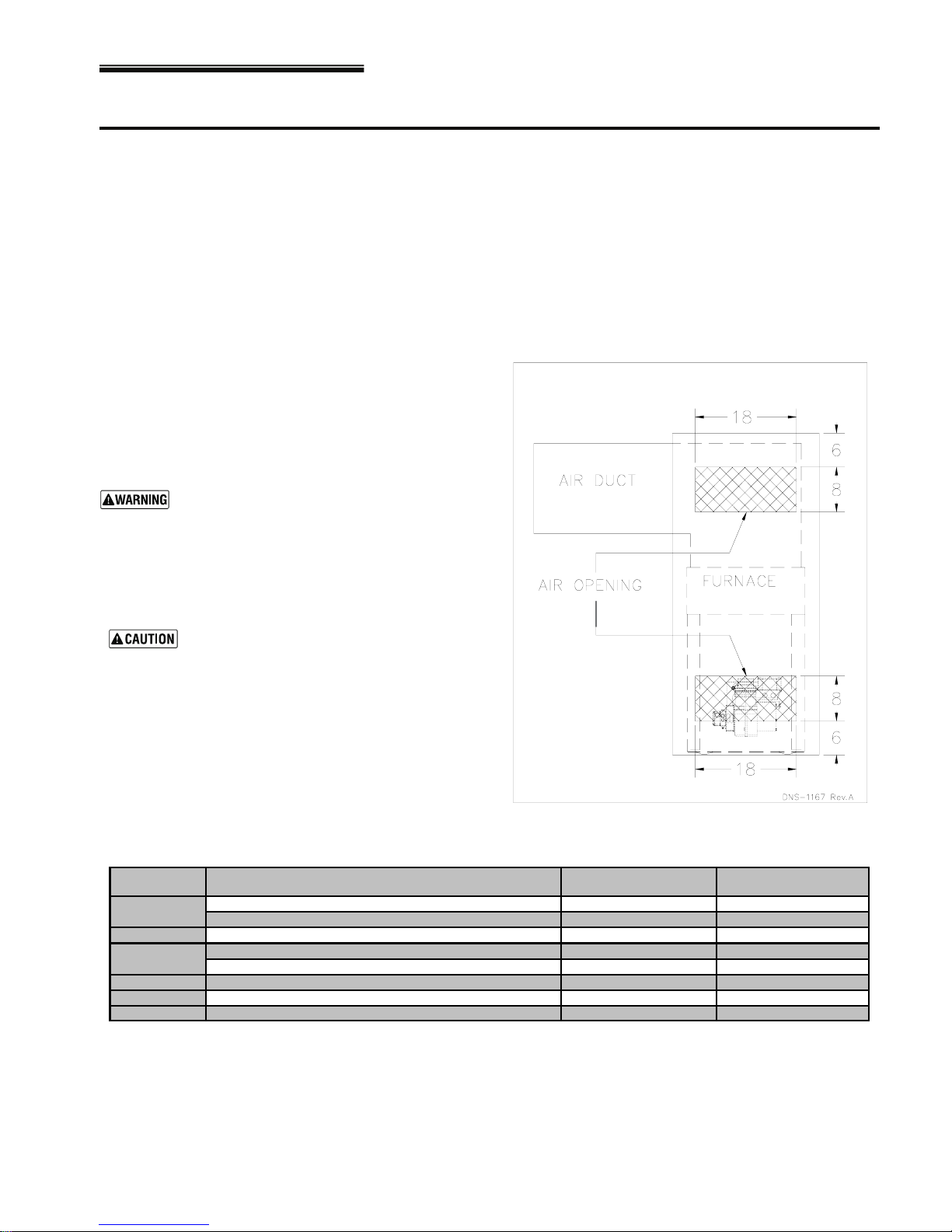
1.1.1. Installation in an enclosure
The unit can be installed in an enclosure such as a closet. However,
2 ventilation openings are required for combustion air. The openings
should be located in front of the furnace approximately 15 cm (6")
above the floor and 15 cm (6") below the ceiling. Figure 1 indicates
the minimum dimensions required and the location of the openings.
Figure 1: Location and dimensions of ventilation air
openings in a closet door
Table 1: Minimum clearances from combustible materials
LOCATION APPLICATION
SIDES
BACK ACCESS PANEL TO BLOWER 10.16 cm (4") 0.6 m (24")
TOP
BOTTOM
FLUE PIPE AROUND FLUE PIPE 22.86 cm (9")
FRONT FURNACE 20.32 cm (8") 0.6 m (24")
11/13 3
FURNACE 2.54 cm (1") 0.6 m (24")
SUPPLY PLENUM WITHIN 6 FEET OF FURNACE 2.54 cm (1")
FURNACE OR PLENUM 5.08 cm (2")
HORIZONTAL WARM AIR DUCT WITHIN 6 FEET OF FURNACE 5.08 cm (2")
FURNACE (COMBUSTIBLE FLOOR) 0 cm (0")
CLEARANCES
(combustible materials)
RECOMMANDED ACCESS
FOR SERVICE
PLB-098 Oil Furnaces – Furnace Manual
1.2. ELECTRICAL SYSTEM
The exterior of the unit must have an
uninterrupted ground to minimize the risk of
bodily harm, if ever an electrical problem
develops. A green ground screw is supplied
with the control box for that purpose.
The appliance must be installed in accordance with the current
ANSI/NFPA 70 National Electrical Code, CSA C22.1 Canadian
Electrical Code Part 1 and/or local codes.
The control system depends on the correct polarity of the power
supply. Connect “HOT” wire (H) and “NEUTRAL” wire (N) as
shown in Figures 9 and 10.
A separate line voltage supply should be used, with fused
disconnect switch or circuit breaker, between the main power
panel and the unit.
Only copper wire may be used for the 115V circuit on this unit. If
wires need to be changed, the replacements must have the same
temperature resistance as the originals.
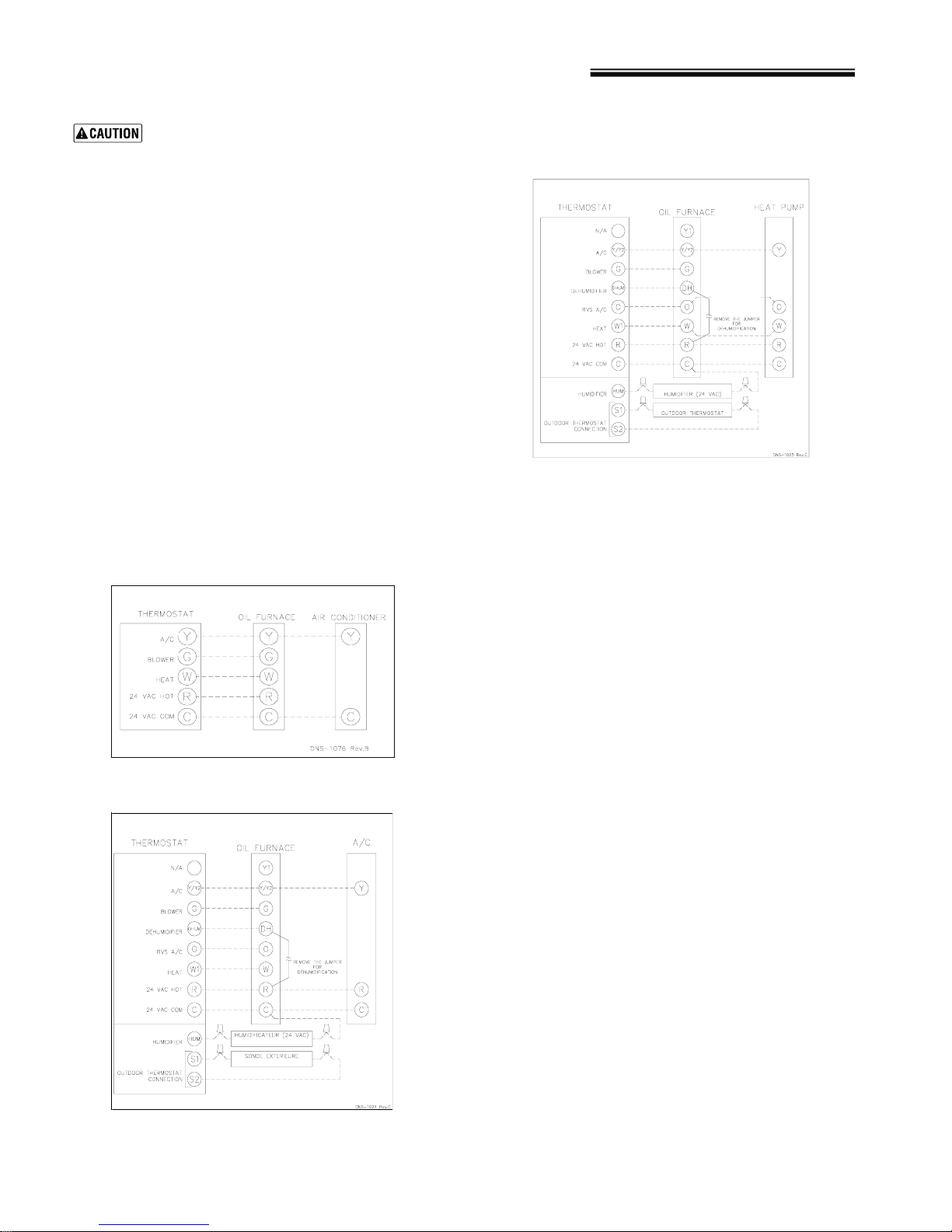
1.3. INSTALLATION OF THE
THERMOSTAT
A thermostat must be installed to control the temperature of the
area to be heated. Follow the instructions supplied with the
thermostat. Also refer to the wiring diagrams provided with the
heating/air conditioning unit. The connections must be made as
indicated on the following diagrams and the wiring diagrams.
Figure 2: Heating & Air Conditioning - With 4 Speed
Motor
Figure 3: Thermostat Wiring- Heating & Air
Conditioning - With ECM Variable Speed Motor
Figure 4: Thermostat Wiring-Heating & Air
Conditioning/HeatPump - With ECM Variable Speed
Motor
1.4. INSTALLATION OF THE BURNER
Refer to the burner manufacturer’s instructions. Also, the burner
must be installed always in the same way independently of the
furnace orientation.
1. Position the mounting gasket between the mounting flange
and the burner mounting plate. Align the holes in the burner
mounting plate with the studs on the mounting flange and
bolt securely in place.
2. Remove the burner drawer assembly or the air tube
assembly;
3. Install the nozzle, refer to Burner data Table 11;
4. Check the electrode settings;
5. Make the electrical connections;
6. Complete oil line connections.
1.4.1. Nozzles
The burner comes equipped with an appropriate nozzle.
However, if another size or a replacement nozzle is required, use
the manufacturer’s recommended spray angle and type a shown
in Table 11 and specified pump pressure.
Always select nozzle sizes by working back from the desired flow
rate at operating pressure and not the nozzle marking.
4 11/13
1.4.2. Air and Turbulator Settings
Before starting the burner for the first time, adjust the air and
turbulator settings to those listed in this manual, Table 11. Once
the burner becomes operational, final adjustments will be
required. Refer to section 2 of this manual.
1.4.3. Post purge delay adjustment
The post purge delay on the oil-fired burners is factory set to zero
second. This delay is applicable for all installations with chimney
venting. For heating units installed with side wall venting and a
burner equipped with this feature, the post purge delay must be
set to 15 seconds (For configuration use the Beckett Contractor’s
Tool "52082U"). No delay is required for Riello burners. Refer to
the burner control instruction manual and markings for proper
adjustment of the post purge delay.
PLB-098 Oil Furnaces – Furnace Manual
1.5. VENTING
Poisonous carbon monoxide gas, fire and
explosion hazard.
Read and follow all instructions in this section.
Failure to properly vent this furnace can result
in death, bodily injury and/or property damage.
To ensure the safe and proper functioning of an
oil furnace, it must always be connected to a
flue with sufficient draft or to an approved sidewall venting system. In addition, it is strongly
recommended to perform a complete inspection
of all the existing venting systems.
Poisonous carbon monoxide gas hazard.
Never install a hand operated damper in the
vent pipe. However, any Underwriters
Laboratories listed, electrically operated
automatic type vent damper may be installed if
desired. Be sure to follow the instructions
provided with vent damper. Also, read and
follow all instructions in this section of the
manual.
Failure to properly vent this furnace or other
appliances can result in death, bodily injury
and/or property damage.
1.5.1. Masonry chimney
This furnace can be vented into an existing masonry chimney.
However, the unit must not be vented into a chimney into which a
solid fuel burning furnace is already being vented.
Before venting this furnace into a chimney, its condition must be
checked and repairs made, if necessary. Also, the chimney lining
and dimensions must conform to local and national codes.
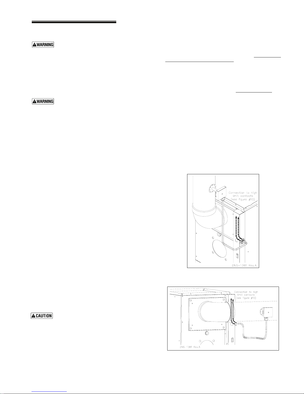
This device is designed to detect the insufficient evacuation of
combustion gases in the event of a vent blockage. In such a case
the thermal switch will shut down the oil burner. The device will
then need to be re-armed MANUALLY.
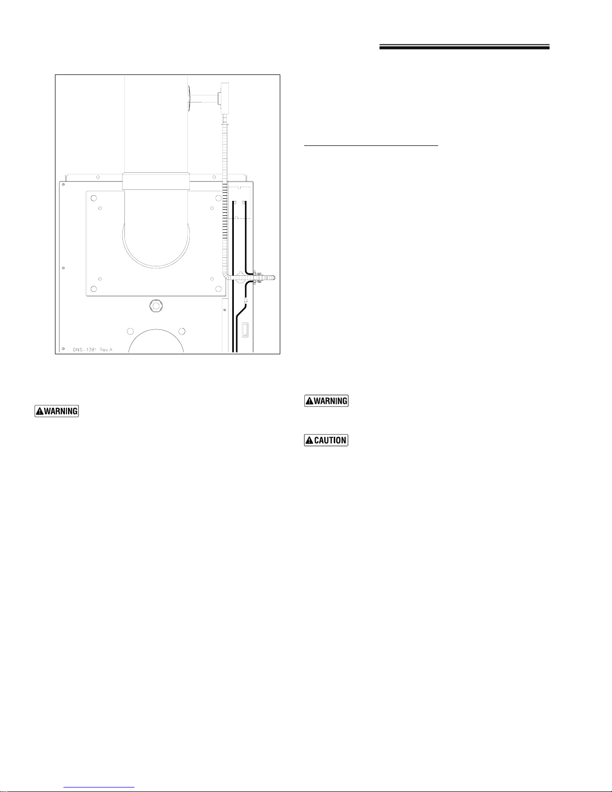
Refer to the detailed instructions and wiring diagrams supplied
with the BVSO for the installation and wiring procedures. The
length of wires supplied with the unit is such that the safety
device must be installed between the flue outlet of the appliance
and the draft regulator, as indicated in the instructions.
It is also essential that the BVSO be maintained annually
more details refer to the instructions supplied with the device
itself, as well as Section 2 of this Manual.
. For
1.6.1. BVSO Performance Test
(If installed)
The purpose of the following test is to check that the electrical
outlet on the furnace, designated to the BVSO, is functional.
1. Start up the burner;
2. Disconnect one wire of the BVSO;
3. The burner must shut-off immediately, while the blower
continues to run to the end of the cool-down cycle.
If the test is not in line with the above, call a QUALIFIED
SERVICE TECHNICIAN.
Figure 5: BVSO mounting installation: Upflow with
vertical exhaust (OPTIONAL)
1.5.2. Factory Built Chimneys
Oil fired furnaces are approved for use with “L” type vents. The
unit may also be used with an approved chimney of proper
dimensions and temperature ratings as specified in the
installation code. Refer to chimney manufacturer’s instructions for
proper installation.
1.5.3. Draft Regulator
It is recommended that a draft regulator be installed in cases
where the draft is either high or variable due to external
conditions. Follow the instructions provided with the regulator.
1.5.4. Side-wall Venting
The heating unit is approved for side-wall venting. This system is
comprised of a model VTK-54 side-wall venter and a 4” insulated
vent pipe, model IFV-410, IFV-420. Refer to the installation
instructions provided with the venting system.
1.6. BLOCKED VENT SHUT-OFF DEVICE
(BVSO) FOR CHIMNEY VENTING OPTIONAL
It is imperative that this device be installed by a
qualified service technician.
A positive pressure venting system (Sealed
Combustion System or Direct Vent) must NOT
use the BVSO. Follow the instructions supplied
with the venting system.
Figure 6: BVSO mounting installation: Upflow with
horizontal exhaust (OPTIONAL)
11/13 5
PLB-098 Oil Furnaces – Furnace Manual
Figure 7: BVSO Wiring (OPTIONAL)
The following areas or types of structures may contain or be
exposed to certain substances, potentially requiring outside air for
combustion:
a. Commercial buildings;
b. Buildings with indoor pools;
c. Furnaces installed near chemical storage areas.
Exposure to the following substances:
a. Permanent wave chemicals for hair;
b. Chlorinated waxes and cleaners;
c. Chlorine based swimming pool chemicals;
d. Water softening chemicals;
e. De-icing salts or chemicals;
f. Carbon tetrachloride;
g. Halogen type refrigerants;
h. Cleaning solvents (such as perchloroethylene);
i. Printing inks, paint removers, varnishes, etc. ;
j. Hydrochloric acid;
k. Solvent based glue;
l. Antistatic fabric softeners for clothes dryers;
m. Acid based masonry cleaning materials.
1.7.2. Burner with Outdoor Combustion
Air Kit
Some burners are designed to function with combustion air taken
directly from the outside. Follow the instructions provided with the
burner, the fresh-air supply kit or the side-wall venting kit.
1.7. COMBUSTION AIR SUPPLY AND
VENTILATION
Poisonous carbon monoxide gas hazard.
Comply with NFPA 31 (U.S.) and CSA B139 (Canada)
standards for the installation of Oil Burning
Equipment and applicable provisions of local building
codes to provide combustion and ventilation air.
Failure to provide adequate combustion and
ventilation air can result in death, bodily injury and/or
property damage.
Oil furnaces must have an adequate supply of combustion air. It is
common practice to assume that older homes have sufficient
infiltration to accommodate the combustion air requirement for the
furnace. However, home improvements such as new windows,
doors, and weather stripping have drastically reduced the volume of
air infiltration into the home.
Refer to oil furnace installation codes relative to combustion and
ventilation air requirements. Consult Section 1.1.1 in this manual,
specifically for units installed in an enclosed space.
Home air exhausters are common. Bathroom and kitchen fans,
power vented clothes dryers and water heaters all tend to create a
negative pressure condition in the home. Should this occur the
chimney becomes less and less effective and can easily downdraft.
In certain cases, mechanically supplied air, by way of a blower,
interlocked with the unit, is necessary. It is the installer’s
responsibility to check that.
1.7.1. Contaminated Combustion Air
Installations in certain areas or types of structures will increase the
exposure to chemicals or halogens that may harm the furnace.
These conditions will require that only outside air be used for
combustion.
1.8. OIL TANK
Fire and explosion hazard.
Use only approved heating type oil in this furnace.
DO NOT USE waste oil, used motor oil, gasoline or
kerosene.
Use of these will result in death, bodily injury
and/or property damage.
When a 0.75 USGPH or smaller nozzle is used, a 10
micron or finer filter, must be installed on the oil
supply line to the furnace inside the building where
the unit is located.
This is a requirement in order for the heat
exchanger warranty to remain in force.
Check your local codes for the installation of the oil tank and
accessories.
At the beginning of each heating season or once a year, check the
complete oil distribution system for leaks.
Ensure that the tank is full of clean oil. Use No.1 or No.2 Heating Oil
(ASTM D396 U.S.) or in Canada, use No.1 or No.2 Furnace Oil.
A manual shut-off valve and an oil filter shall be installed in
sequence from tank to burner. Be sure that the oil line is clean
before connecting to the burner. The oil line should be protected to
eliminate any possible damage. Installations where the oil tank is
below the burner level must employ a two-pipe fuel supply system
with an appropriate fuel pump. A rise of 2.4 m (8') and more requires
a two stage pump and a rise greater than 4.9 m (16') an auxiliary
pump. Follow the pump instructions to determine the size of pipe
needed in relation to the rise or to the horizontal distance.
6 11/13
PLB-098 Oil Furnaces – Furnace Manual
1.9. CONNECT SUPPLY AND RETURN
DUCTS
1.9.1. Duct sizing
1.9.1.1. Determine airflow CFM
The temperature rise through the furnace must not exceed 85oF, but
should be at least 55°F for comfort. When calculating airflow,
assume a temperature rise of 70°F.
The noticeable temperature change for cooling would be
approximately 27-30°F. Actual temperature change will be
approximately 18-21°F due to humidity of the air.
To calculate noticeable heat temperature change (ΔT), you can use
the formula:
ΔT = BTU/h / (1.1 x CFM) Eq. 3 - 1
To calculate air flow when you know temperature change (ΔT), you
can use:
CFM = BTU/h / (1.1 x ΔT) Eq. 3 - 2
You can estimate air flow using the following rules of thumb:
Heating: 14 CFM per 1,000 BTU/h output Eq. 3 - 3
Cooling: 400 CFM per ton air conditioning Eq. 3 - 4
Determine the required airflow based on whichever is larger: heating
mode or air conditioning mode.
Examples:
1. What would the temperature rise be for a 100,000 BTU/h output
furnace with an airflow rate of 1200 CFM?
Use Equation 3-1 since you know CFM and BTU/h:
ΔT = 100,000 / (1.1 x 1200) = 76°F
• The temperature rise would be 76°F.
• If the air enters the furnace at 70°F, it would leave the
furnace at 70°F + 76°F = 146°F.
2. What would the airflow be to obtain a 70°F rise through a
120,000 BTU/h output furnace?
Use equation 3-2 since you know ΔT and BTU/h:
CFM = 120,000 / (1.1 x 70) = 1558 CFM
• The air flow would have to be 1558 CFM to obtain a
temperature rise of 70°F.
3. Estimate the required airflow for a 75,000 BTU/h output furnace
installed with a 2-ton air conditioning evaporator coil.
Heating mode air flow (use Equation 3 - 3):
CFM = 75 x 14 = 1050 CFM
Cooling mode air flow (use Equation 3 - 4):
CFM = 2 x 400 = 800 CFM
• The larger number is 1050 CFM (heating), so the duct
system should be sized for 1050 CFM.
• The supply duct would need to be 16” round or a rectangular
equivalent such as 8” x 25" or 12" x 18", using Table 3.
4. Estimate the required airflow for the same furnace installed with
a 4-tons air conditioning evaporator coil.
Heating mode airflow is still 1050 CFM.
Cooling mode air flow (use Equation 3 - 4):
CFM = 4 x 400 = 1600 CFM
• The larger number is 1600 CFM (cooling), so the duct
system should be sized for 1600 CFM.
• The supply duct would need to be 18” round or a rectangular
equivalent such as 8" x 36" or 12" x 23", using Table 3
Always check the size of existing ducts,
particularly if you are adding air conditioning.
The air pressure loss through the cooling
evaporator coil reduces available airflow. If the
ducts are too small as well, the system may not
work satisfactorily on either heating or cooling.
1.9.1.2. Determine duct dimensions
Tables 3 and 4, provide typical round and rectangular duct sizes for
rectangular and flat oval galvanized ducts. Do not apply these tables
to size ductwork if the total equivalent length of the duct exceeds
approximately 100 feet. For longer systems or for duct board,
fiberglass-lined or flexible duct sizing, use the ACCA Manual D or
the ACCA duct sizing slide rule. These tables are based on pressure
loss of approximately 0.10” water column per 100 feet equivalent
length of duct.
Use Table 2 below to size or check sizing of take-offs to supply
registers or return grills.
Verify the size and type of registers, diffusers and grills from the
manufacturer’s ratings. Do not exceed the recommended flow rate.
The pressure drop allowance for each should not exceed
approximately 0.05” water column.
Install a return air filter, sized per specifications in Table 10.
Use only a return air filter mounted to the furnace. Do not add
additional filters unless the duct system is carefully sized to allow for
the additional pressure drop.
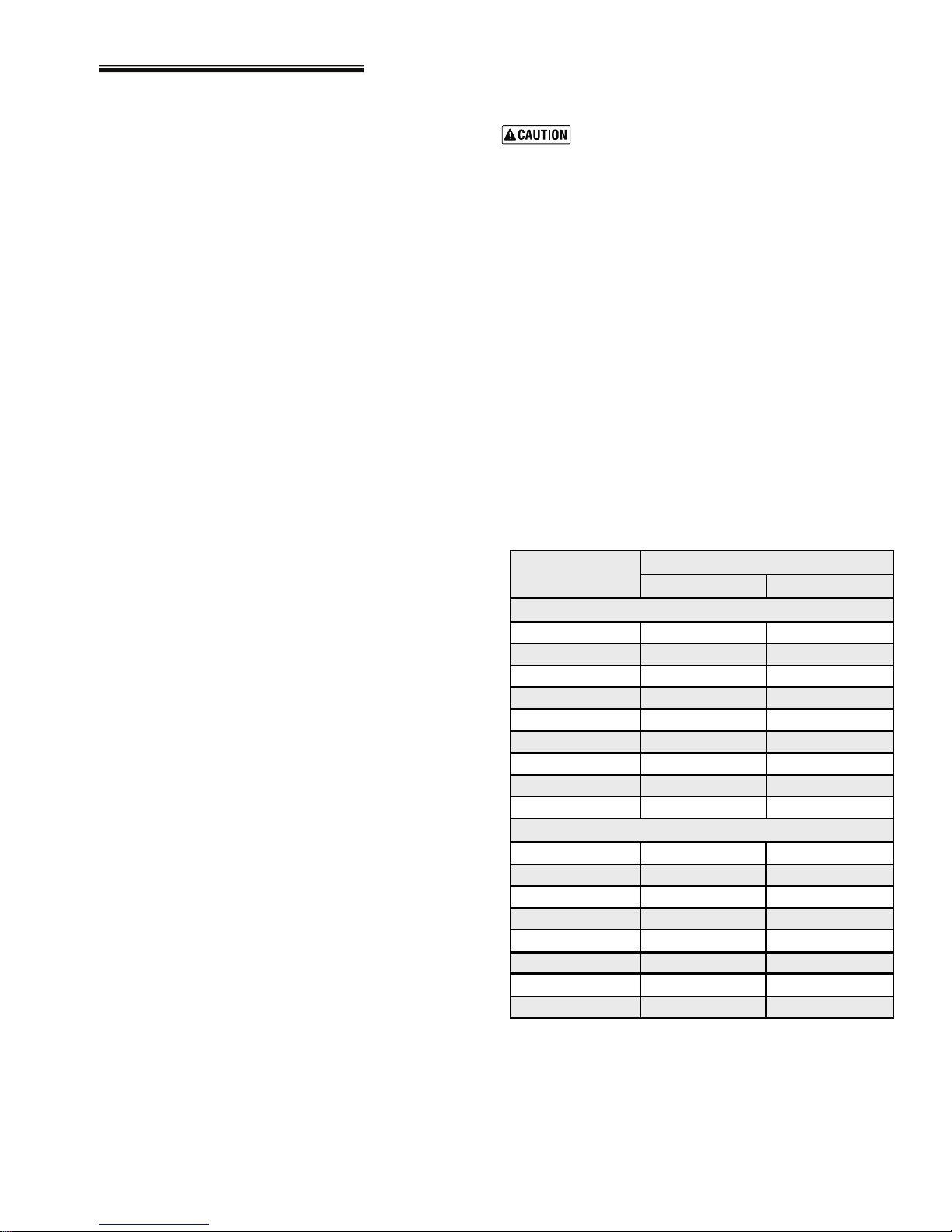
Table 2: Suggested maximum flow to run outs
TAKE-OFF SIZE
(Inches)
Sheet metal or ductboard
5 Round 60 45
6 Round 100 75
7 Round 140 110
8 Round 210 160
3 ¼ x 8 Stack 70 55
3 ¼ x 10 Sta ck 100 75
3 ¼ x 14 Sta ck 140 110
2 ¼ x 12 Sta ck 70 55
2 ¼ x 14 Sta ck 90 70
Flexible duct (keep bends to minimum)
6 Round 55 40
8 Round 120 90
10 Round 200 160
12 Round 320 250
14 Round 480 375
16 Round 660 530
18 Round 880 680
20 Round 1200 900
SUPPLY RETURN
CFM
11/13 7
PLB-098 Oil Furnaces – Furnace Manual
1.9 CONNECT SUPPLY AND RETURN DUCTS (continued)
1.9.1 Duct sizing (continued)
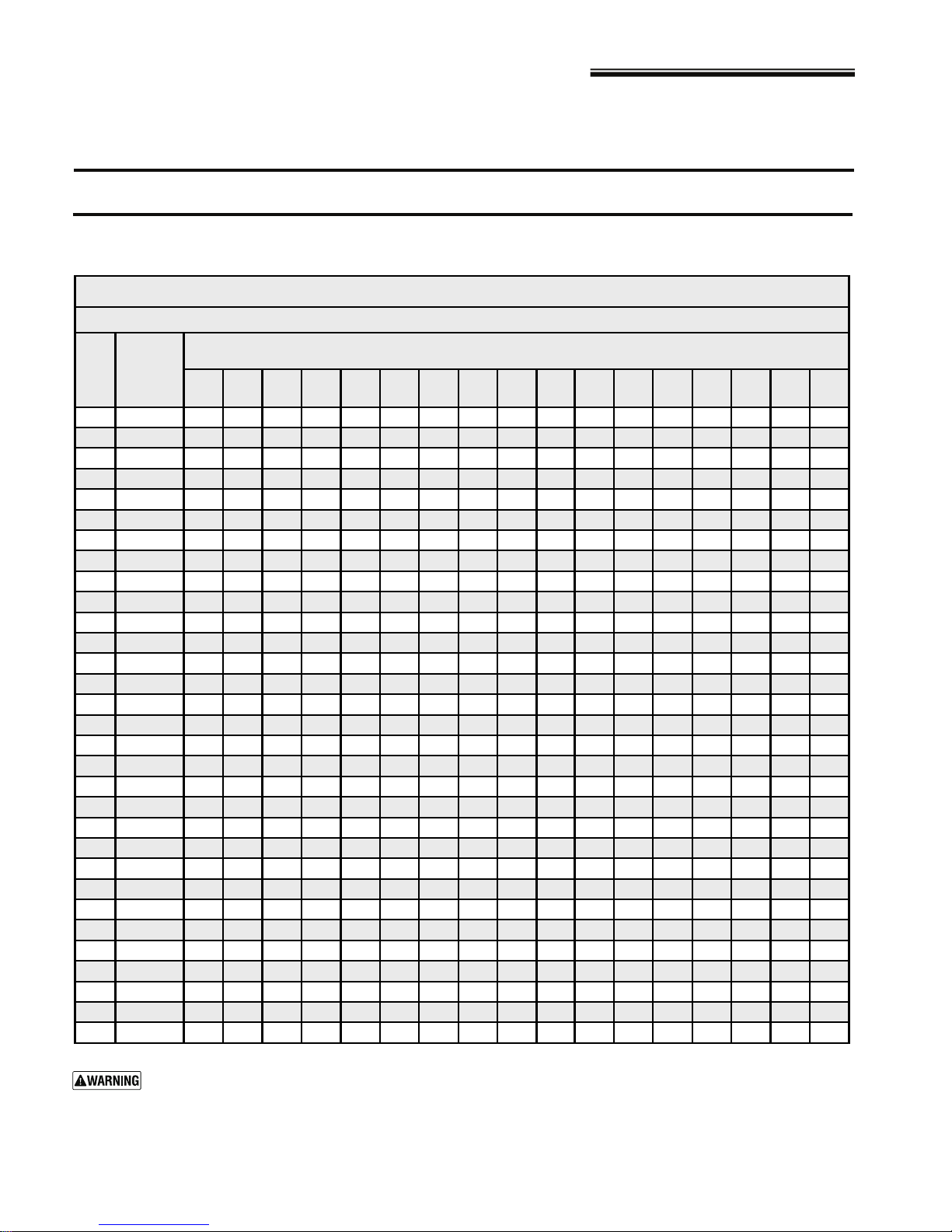
Table 3: Typical duct sizing for systems not over 100 feet equivalent length – round or rectangular galvanized
CFM
(For approximately 0.10 inch w.c. in a typical residential installation of galvanized metal duct)
Round
duct
diameter4567891012141618202224262830
(inches)xxxxxxxxxxxxxxxxx
45
65
100
150
200
250
300
400
500
600
700
800
900
1000
1100
1200
1300
1400
1500
1600
1700
1800
1900
2000
2200
2400
2600
2800
3000
3500
4000
Rectangular duct equivalent sizes
Minimum width
4
5
6
7
8
9
9
10
12
12
12
14
14
16
16
16
16
18
18
18
18
18
20
20
20
22
22
22
22
24
26
444--------------
6544- - - - - - - - - - - - -
865544- - - - - - - - - - -
1297655544-- - - - - - -
141198766544- - - - - - -
18 13 10 9 8 7 6 6 5 5 4 4 - - - - -
20 15 12 10 9 8 7 6 6 5 5 4 4 - - - -
2619151311109876655544-
322318151312119876665555
3828221815131210987766655
46322520171514111098777666
523628231917151311109887766
5841312521191714121110988777
6445342823201815131110998877
72493830252219161412111099887
-5441332724211715131211109988
- 58443529252218161412111010 9 9 8
- 6347383127241916141312111010 9 9
- 685140342925201715141212111010 9
- 725443363027211816141312111110 9
- - 58 45 38 32 28 23 19 17 15 14 13 12 11 10 10
- - 61 48 40 34 29 24 20 17 16 14 13 12 11 11 10
- - 64 51 42 35 31 25 21 18 16 15 14 13 12 11 11
- - 68 53 44 37 32 26 22 19 17 15 14 13 12 12 11
- - - 59 48 41 35 28 23 20 18 16 15 14 13 12 12
- - - 64 52 44 38 30 25 22 19 17 16 15 14 13 12
- - - 69 56 47 41 32 27 23 21 19 17 16 15 14 13
----61514434292522201817151514
----65544737302623211917161514
-----635442342926232119181716
-----726147393329262321201918
Do not apply this table for duct systems over approximately 100 equivalent feet length. For longer systems or
systems using other duct materials, refer to ACCA Manual D. Incorrectly sizing duct systems can result in unsafe or
uncomfortable operation.
(inches)
Typical duct sizing
for duct heights
(inches)
of :
8 11/13
 Loading...