

Williams Electronics Stellar Wars User Manual
16P-490-100
Game No.
490
March,1979
TELLfI~
lIJfI~S
For
service call TOLL-FREE:
800-621-4765
In
Illinois call
800-972-7898
A
CiJfiUiawM@
W
EL.ECTRONICS.
INC.
An
Xcor
International
Inc. <;:ompany
3401 N. California Ave., Chicago, IL_60618
Cable Address:
WILCOIN,
CHICAGO
(312) 267-2240
490
CONTENTS
Section Page
1.
INSTALLATION 2
Assembly and Interconnection
...............•...
2
Inspection 3
Power Turn-On 6
2.
GAME OPERATION 6
3.
GAME
ADJUSTMENTS
7
General Procedure 7
High Score to Date 9
Replay Scores 9
Maximum Credits 9
Standard Game
Pricing.
"
10
Custom Game Pricing
10
Pricing Formula
11
Credits in Game
12
High Score Credits
12
Play
12
Match
13
Special
'"
13
Scoring Awards
13
NumberofBalls
.........................•....
14
Maximum Plumb Bob Tilts
14
Unique Game Adjustments
14
Restoring Factory Settings
15
4.
GAME BOOKKEEPING AND EVALUATION..15
Feature Access
15
High Score Reset
16
Resetting Audit Totals
16
5.
BUILT-IN DIAGNOSTICS
16
Display Digits Test
16
Lamp
Test-Test
01
16
Solenoid
Test-Test
02
18
Switch
Test-Test
03
18
Auto Cycle Mode
18
6.
MAINTENANCE
20
Board Replacement
20
CPU
Board Self-Test
22
Sound Board Self-Test
22
Troubleshooting Charts
23
Lamps
23
Switches
23
Solenoids
24
Master Display
24
Player Display
24
Game Operation
25
Inoperative or Blows Fuses
25
Losing Memory
25
No Response to CPU Self-Test or
Intermittent Operation
26
Sound Problems
26
7.
INTERCONNECTION CHARTS
26
8.
MECHANICAL
ADJUSTMENTS
37
9.
SPARE
PARTS
37
SECTION 1
INSTALLATION
This section provides
information
for
assembly
and
interconnection, inspection, and power turn-on for solid
state pinballs.
ASSEMBLY AND INTERCONNECTION
To assemble and interconnect the game, proceed as follows:
2
1.
Remove the two cartons and the cabinet from the
shipping carton.
2.
Carefully set the cabinet on end with the rear of the
cabinet on the floor.
3.
Open the stapled carton and remove the four legs and
the cashbox.
4.
Remove the ball, eight acorn bolts and four backbox
mounting bolts from the cash box.
5.
Mount
the two front legs using four acorn bolts.
6.
Carefully lower the cabinet so that it is supported on the
front legs.
7.
Take the· backbox from its carton and remove the
envelope containing the back
box
keys from the topofit.
8.
Centerthe backbox onthefloorattherearofthecabinet
in an upright position oriented with the insert board
parallel to the length
of
the cabinet.
9.
Lift up the rearofthe cabinet
an
slide the
backbox underneath it for suppor
10.
Mount
the two rear legs using four a
11.
Reach into the large holeatthe rear 0
out the power cord, and place it in
NOTE
Do
not
plug the game in and do not pull
from the cabinet
at
this time.
12.
The backbox has a metal bracket prot from the
bottom hole that will engage a simila ket on the
cabinet pedestal to prevent the backb
rom
tipping
forward when the insert door
is
opened. Place the
backbox onto
the pedestal, engaging the bracket.
13.
Remove the shipping blocks from the insert door.
14.
Lift uponthe latchatthe right sideofthe insert door
and open the door.
15.
Secure the backbox to the cabinet using the four bolts
and washers.
NOTE
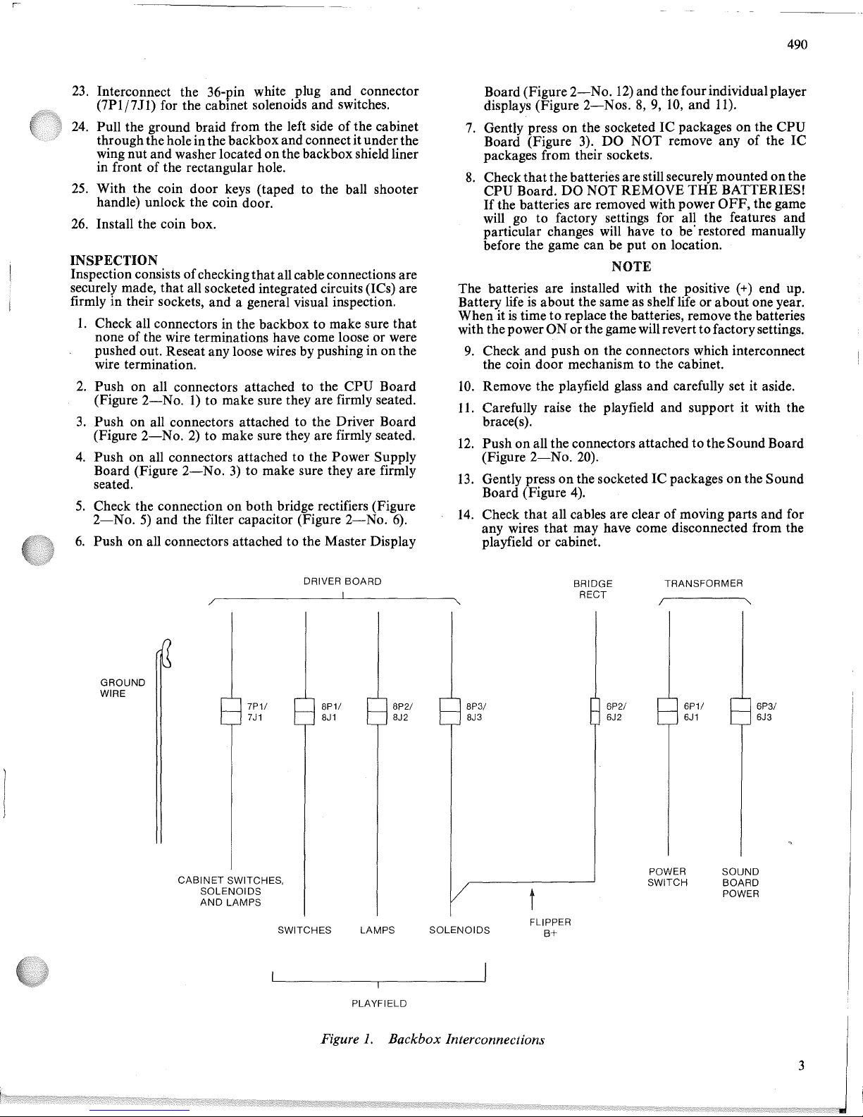
Refer
to
Figure1.There are seven cables (four from the
playfield
and
three
from
the cabinet)
that
must
be
interconnected
with
cables
from
the
backbox.
The
connectors are size and color coded except for the power
switch to transformer connection, where the colors do not
match.
16.
Reach into the cabinet through the hole in the backbox
and pull out all cables.
17.
Interconnect the 24-pin black plug and connector
(8P3/8J3) for the playfield solenoids.
18.
Interconnect the 24-pin white plug and connector
(8P2/8J2) for the playfield lamps.
19.
Interconnect the IS-pin white plug and connector
(8Pl/8Jl)
for the playfield switches.
20.
Interconnect
the 3-pin white
plug
and
connector
(6Pl/6J1)
for the switched ac power to the transformer.
21.
Interconnect
the
I-pin
white plug
and
connector
(6P2/6J2) for the flipper solenoid
B+.
22.
Interconnect
the 9-pin white
plug
and connector
(6P3/6J3) for the sound board power.
23.
Interconnect the 36-pin white plug and connector
(7Plj7J1)
for the cabmet solenoids and switches.
24.
Pull the ground braid from the left side ofthe cabinet
throughthe hole in the backboxand connectitunder the
wing nut and washer located on the backbox shield liner
in front of the rectangular hole.
25.
With the coin door keys (taped to the ball shooter
handle) unlock the coin door.
26.
Install the coin box.
INSPECTION
Inspection consists
of
checkingthatall cable connections are
securely made, that all socketed integrated circuits (lCs) are
firmly in their sockets, and a general visual inspection.
1.
Check all connectors in the backbox to make sure
that
none of the wire terminations have come loose or were
pushed out. Reseat any loose wires by pushing in
on
the
wire termination.
2.
Push on all connectors attached to the CPU Board
(Figure
2-No.
1) to make sure they are firmly seated.
3.
Pushonall connectors attached to the Driver Board
(Figure
2-No.2)to make sure they are firmly seated.
4.
Push on all connectors attached to the Power Supply
Board (Figure
2-No.3)to make sure they are firmly
seated.
5.
Check the connection on both bridge rectifiers (Figure
2-No.5)and the filter capacitor (Figure
2-No.
6).
6.
Push on all connectors attachedtothe Master Display
490
Board(Figure
2-No.12)
and the fourindividual player
displays (Figure
2-Nos.8,9,
10,
and
11).
7.
Gently pressonthe socketedICpackages on the
CPU
Board (Figure
3).
DO
NOT remove any of the
IC
packages from their sockets.
8.
Checkthatthe batteriesare still securely mounted onthe
CPU Board.
DO
NOT REMOVE
THE
BATTERIES!
If
the batteries are removed with power
OFF,
the game
will go to factory settings for all the features and
particular changes will have to be'restored manually
before the game can be put on location.
NOTE
The batteries are installed with the positive
(+) end up.
Battery life
is
about the same as shelf life or about one year.
When it
is
timetoreplace the batteries, remove the batteries
with the power ON or thegame will revert
to
factory settings.
9.
Check and push on the connectors which interconnect
the coin door mechanism to the cabinet.
10.
Remove the playfield glass and carefully set it aside.
11.
Carefully raise the playfield and support it with the
brace(s).
12.
Pushonall the connectors attachedtotheSound Board
(Figure
2-No.
20).
13.
Gently pressonthe socketedICpackagesonthe Sound
Board (Figure
4).
14.
Check that all cables are clear of moving parts and for
any wires that may have come disconnected from the
playfield or cabinet.
DRIVER
BOARD
/~--
---,I
~
GROUND
WIRE
BRIDGE
RECT
TRANSFORMER
/
"
7P11
7J1
CABINET
SWITCHES,
SOLENOIDS
AND
LAMPS
8P11
8J1
8P21
8J2
t
6P21
6J2
6P11
6J1
POWER
SWITCH
6PSI
6JS
SOUND
BOARD
POWER
SWITCHES LAMPS
PLAYFIELD
SOLENOIDS
FLIPPER
B+
Figure
1.
Backbox Interconnections
3
-..
.j:>.
.j:>.
\0
o
I
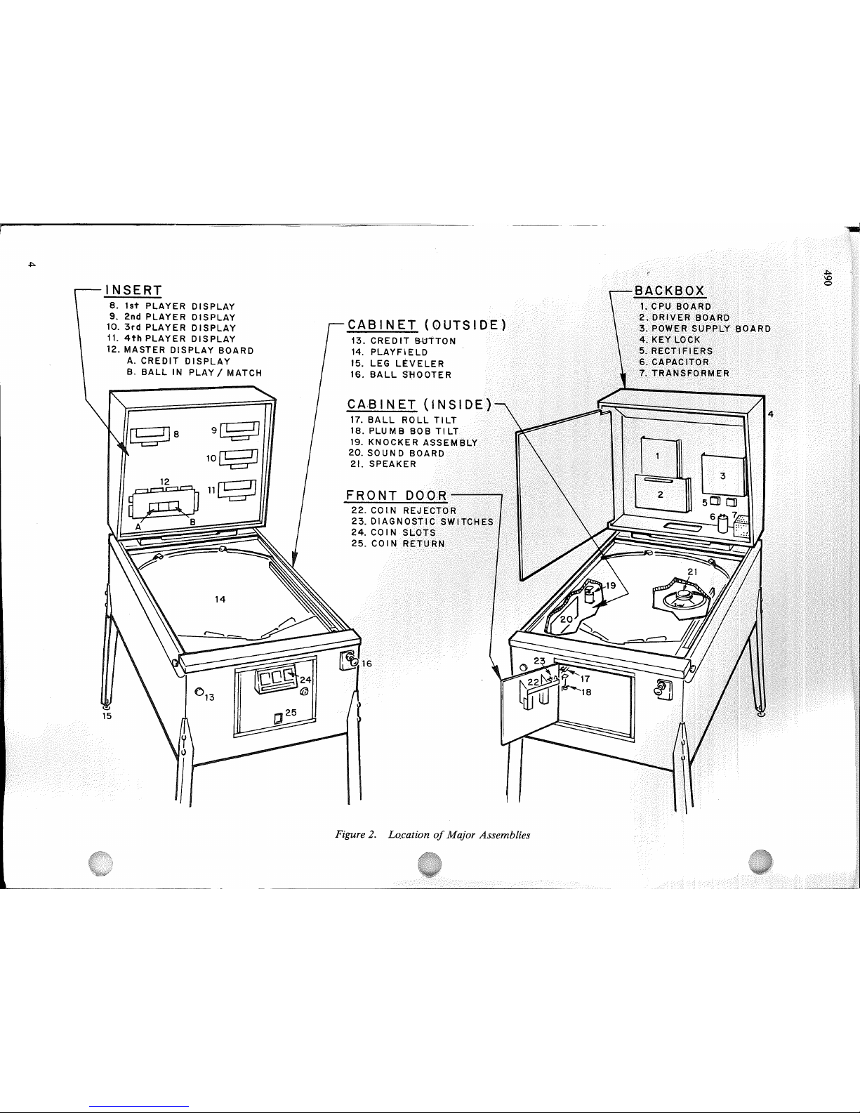
CABINET
(OUTSIDE)
13.
CREDITB-ltTTON
14.
PLAYFIELD
15.
LEG
L1tVELER
16.
BALL
S~OOTER
CA,BINET
(lNSID
17.
BALL
ROLL
TILT
18.
PLUMB
BOB
TI
19.
KNOCKER
ASS
20.SOUND
BOARD
21.
SPEAKER
FRONT
DOOR
22.
COIN
REJECTOR
23.
DIAGNOSTIC
S
24.COI N
SLOTS
25.
COIN
RETUR
9[SD
10~
11~
~
Sa
INSERT
8.
1st
PLAYER
DISPLAY
9.
2nd
PLAYER
DISPLAY
10.
3rd
PLAYER
DISPLAY
11.
4th
PLAYER
DISPLAY
12.
MASTER
DISPLAY
BOARD
A.
CREDIT
DISPLAY
B.
BALLINPLAY/MATCH
I
\!)
15
Figure2.Lo.cationofMajor Assemblies
490
MPU
NOT
USED
DIAGNOSTIC
MASTER
COMMAND
ENTER
MASTER
COMMAND
CLOCK
mrumruo
PROM
PROM
ROM
ROM
#2
#1
5A-9196 5A-9197
IK~~:~~:JI
PROM
#3
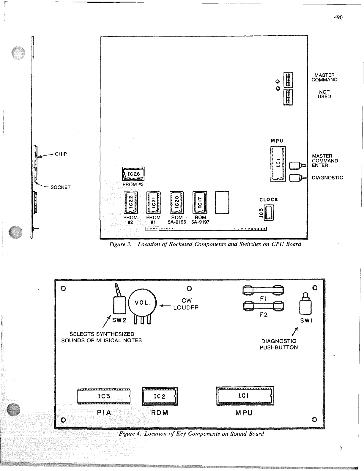
Figure
3.
LocationofSocketed Components
and
Switches on CPU Board
o
b~
0
\
VOL
CW
•
~
LOUDER
!SW2
SELECTS SYNTHESIZED
SOUNDS
OR
MUSICAL NOTES
0 0
0
F1
CJ
0
0
F2
SWI
!
DIAGNOSTIC
PUSHBUTTON
Lo(~ati(m
of
Key Components on
Sound
Board
II
l?:~::::
II
MPU
o
490
15.
Checkswitches for loosesolder
or
"H,,,,
..
f,,,.,,,;
••
n
IIlat,eriial
that
may
have come loose during
shilpnlel1lt.
16.
Check wiresoncoils for proper soldering.
17.
Check
that
the flipperB+fuse on the playfieldissecure
and
that
the fusesonthe sound board and the two fuses
adjacent to it are secure.
18.
Check adjustmentofthe tilt switches:
a. Playfield Shakeonthe bottomofthe playfield.
b.
Plumb
Bob and Ball Roll tilts (Figure 2 Nos.18and
17).
c.
Slam Tiltonthe coin door.
19.
Install the ball in the ball roll tiltifnot already installed
and insert the captive ball through the slot in the plastic
in the lane for the upper left Bull's-Eye target.
20.
Lower the playfield and check that the four fusesonthe
Power Supply Board are secure.
21.
Check adjustments
of
the ball shooter guide using
information provided in Section
8.
POWER
TURN-ON
Thismachine
MUSTBEPLUGGED
INTOA
PROPERLY
GROUNDEPQUTLETto
PREVENT
SHOCK
HAZ-
ARDiandtoiinsllrePROP.E;RGAME
OPERATION.
DO
NOT use a "ch.eater plug"<todefeat the ground pinonthe
power
cord,andpONOTcutoffth.e
ground pin. The line
voltage
MUST
agree with
that
specifiedonthe shipping
cartonorserious damage to thega.l.Ile>willgccur when it
is
~~ufo1f~~~:'
To apply
power.and.c~e00iosttheg0111e'iProceed
1.
Plug the power cord into.anoutletal1dturnonthe
power switch located near
therightJrontcal:>in~tleg.
The game should comeonin the game
over<tn()~ea.s
indicated by the player scores reading
zero,playerJllp
~~f: ~l~~~~~fin~a~h~~~~
l~~~e~iti
~~~r~~e.
hignScsretS.
2.Ifthe game comesonwith the numberofcredits display
(Figure
2-N
o. 12A) showing 04, the ball inplaydisplay
(Figure
2-No.
12B) showing 00, and the player 1
display showing the
PROM
identification and revision
number, turn the game
OFF
and then
ON
again. The
game should now come up in the game over mode.
NOTE
Indications in step 2 are a resultofthe batteries being
removed with the power
OFForcoming loose during
shipment. This has also resulted in features reverting to
factory settings
and
any changes from the factory
settings must be re-entered usingprocedures provided in
Section 3ofthis manual.
3.Ifthe game does not comeupin the game over mode
after Steps 1 and2, refer to troubleshootingin Section
6.
4.
Perform diagnostic tests in accordance with procedures
provided in Section 5ofthis manual.
5.
Make any desired changes to features in accordance
with procedures provided in Section 3ofthis manual.
6.
Latch the insert
door
into position.
7.
Release the backglass retainer
bar
with the backbox
keylock, insert the backglass, and secure the backglass
with the keylock.
6
usingSection 2as a guide.
This Section provides
an
of
game operation.
Place the ball onto the When the
gameisturnedonit come mode. All
player scores will be zero, high score
to
will alternate
with the player 1 score, the player 1 up light will flash, and
the game over lights will light.
When coins are inserted, credits will be posted. The knocker
will sound for each credit. When the credit buttononthe
frontofthe cabinetispressed, the outhole kicker serves the
ball, the credit display will be reduced by one, the ball inplay
will show1,the startup tune will be played, and the player I
up light will flash until the first switchorbumperismade.
Pressing the credit buttonatany time before the ball in play
display indicates 2 will allow additional players, change the
numberofplayer lights, and reduce the numberofcredits by
one for each additional player.
The bonusisadvanced byeachwire form rollover, each drop
target, the eject hole and the captive ball target. The bonus
multiplierisadvanced by spotting
"I"
through "4", spotting
S-T-E-L-L-A-R, and spotting W-A-R-S. SpottingS-T-E-LL-A-R and W-A-R-S scores 50,000.
The left 3-bank drop targets spots S-T as indicated by the
arrows with general illumination bulbs. Making all targets
on
the left 3-bank the first time scores 5000 and lights the top
jet
bumpers. Making them a second time scores 10,000 and
flashes the top
jet
bumpers. Each additional time they are
made scores 5000. The top jet bumpers each score
100,
1000
when lit, and 2000 when flashing.
The 4-bank drop targets spots E-L-L-A as indicated by the
arrows with general illuminationbulbs. Makingall targets in
the
4-bank
scores 5000
and
advances lightingofthe eject
h()le1amps for a possible
Extra
Ball
and
towardslighting the
outla~erollovers
for a possible special.
The center. target in the right 3-bankofdrop targets* spots
":R..".1Vf~kingall
targets in the right 3-bank the first time
scores5000;.asecond time scores 10,000, a third time scores
15,OOO,aJol1rthtime scores 20,000 and fith
and
succeeding
til.Ilesscore. 30,000. In addition, making all targets in this
bank
advances lighting
of
the captive ball,
bottom
jet
bumpers, the spinners,
and
the lower right bull's-eye target
Special. The captive ball target scores 5000 and when lit
scores 10,000 and spots a letter in
STELLAR
WARS. The
bottom
jet bumpers and spinners score
100
and 1000 when
lit. The lower right Bull's-Eye target scores 2000.
All standups and kickers score
10.
All other scoringisas
previously describedoras indicatedonthe playfield. Partial
spotting
of"I"through"4" and bonus multipliers below 5X*
are restored for subsequent balls. Lightingofeject hole
lamps* are also restored for subsequent balls.
Extra
ball* won during the courseofthe gameisplayed
immediatelyafter the player's regular ball enters the outhole.
After the last ballisplayed, the match digits* appear where
the ball in play digits were.Ifmatch occurs an extra credit
will be awarded,*the game over tunewill play
at;ld
the game
over lights will light. The high score to date
wIll
alternate
with the winning player's score.
If
a player's score exceeds the current high .score to date,
three'" credits will be awarded, the game
wIll
playa
high
I
J
490
score to date tune,
and
the highest score to date lights will
remain lit.
The
Plumb
Bob Tilt tilts the ball in playonthe third*
closure. The Ball Roll
and
Playfield Shake tilt switches tilt
the ball in play immediately. The Slamtilt switch onthe coin
door
sets all player scores to zero and returns the game
to
game over.
If
coins are insertedorcredits won and the maximum'"
numberofcreditsisexceeded, the credits will be posted
correctly
but
the coin lockout coil will be de-energized until
the number
of
remaining creditsisbelow the maximum.
While the coil
is
de-energized, no credits may be won and
any coins inserted will be rejected.
"'These features are adjustable and the procedureisoutlined
in Section
3.Inaddition, thereisno background sound
when the Sound Board
is
set for musical notes.
SECTION 3
GAME
ADJUSTMENTS
This section provides
information
for
making
game
adjustments
and
reviewing game status. Williams now
provides a greatly simplified method
of
customizing the
game to the location
or
the operator's requirements. This
section provides detailed procedures for making these
changes.
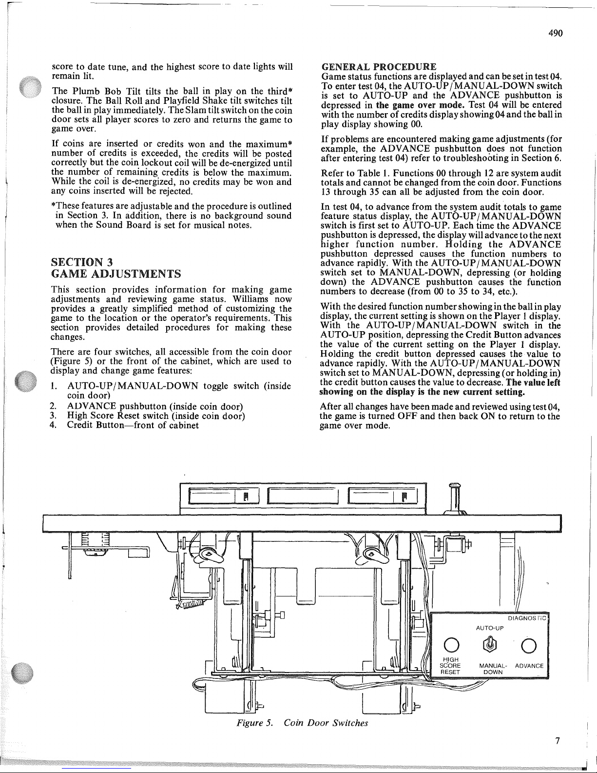
There are four switches, all accessible from the coin
door
(Figure5)or
the frontofthe cabinet, which are used to
display and change game features:
1.
AUTO-UP/MANUAL-DOWN
toggle switch (inside
coin door)
2.
ADVANCE
pushbutton
(inside coin door)
3.
High Score Reset switch (inside coin door)
4.
Credit
Button-front
of
cabinet
GENERAL
PROCEDURE
Game status functions
are
displayed and can be set in test04.
To enter test 04, the AUTO-UP/
MANU
AL-DOWN switch
is
set to AUTO-UP and the ADVANCE pushbutton
is
depressed in the game over mode. Test 04 will be entered
with the number
of
credits displayshowing04
and
the ball in
play display showing
00.
If
problems are encountered making game adjustments (for
example, the ADVANCE pushbutton does
not
function
after entering test 04) refer to troubleshooting in Section
6.
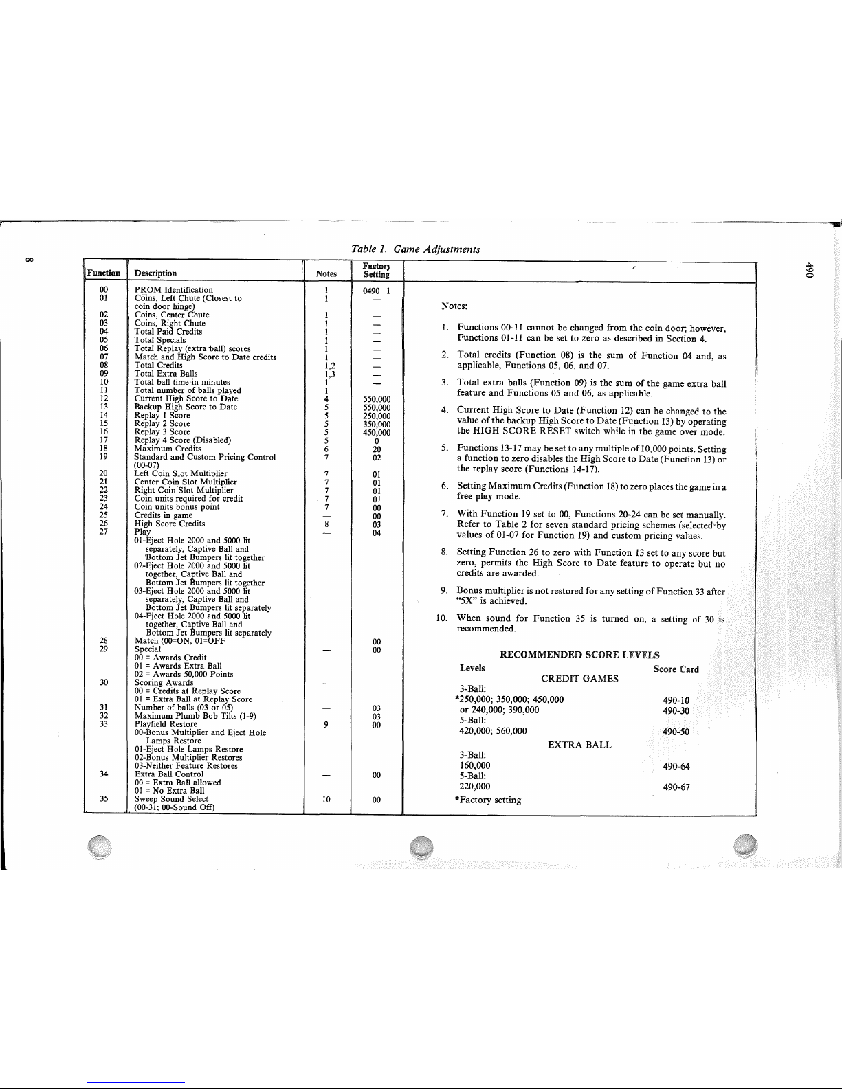
Refer to Table1.Functions 00 through12are system audit
totals
and
cannot be changed from the coin door. Functions
13
through35can all be adjusted from the coin door.
In
test 04, to advance from the system audit totals to game
feature status display, the
AUTO-UP/MANUAL-DOWN
switchisfirst set to AUTO-UP.
Each
time the ADVANCE
pushbutton
is
depressed, the display will advanceto thenext
higher
function
number.
Holding
the
ADVANCE
pushbutton depressed causes the function numbers to
advance rapidly. With the
AUTO-UP/MANUAL-DOWN
switch set to
MANUAL-DOWN,
depressing (or holding
down) the ADVANCE pushbutton causes the function
numbers to decrease (from 00
to35to 34, etc.).
With the desired function numbershowingin the ballin play
display, the current setting
is
shownonthe Player 1 display.
With the
AUTO-UP/MANUAL-DOWN
switch in the
AUTO-UP
position, depressing the Credit Button advances
the value
of
the current setting on the Player 1 display.
Holding the credit
button
depressed causes the value to
advance rapidly. With the
AUTO-UP/MANUAL-DOWN
switch set to
MANU
AL-DOWN, depressing (orholding in)
the credit
button
causes the value to decrease. The value left
showing
on
the display is the new current setting.
After all changes have been made
and
reviewedusing test04,
the game
is
turned
OFF
and then backONto return to the
game over mode.
AUTO-UP
DIAGNOSfiC
o
@J
0
HIGH
SCORE
MANUAL-
ADVANCE
RESET DOWN
I " I
I I
CUI
I
~
r:
f
Figure
5.
Coin Door Switches
7
00
Table1.Game Adjustments
I
Factory
r
IFunction .
, Description
Notes
Setting
00
PROM
Identification
I
0490
I
01
Coins, Left Chute (Closest to
I
-
coin door hinge)
Notes:
02
I Coins, Center Chute
I
-
03
Coins, Right Chute
I
-
1.
Functions
00-11
cannotbechanged
from
the
coin
door;
however,
!
04
Total Paid Credits
I
-
Functions
01-11
canbesettozeroasdescribedinSection
4.
,
05
Total Specials
I
-
06
Total Replay (extra ball) scores
I
-
2.
Total
credits
(Function
08) is
the
sumofFunction04and,
as
07
Match and High Score to Date credits
I
-
08
Total Credits
1,2
-
applicable,
Functions
05, 06,
and
07.
I
09
Total Extra Balls
1,3
-
10
Total ball timeinminutes
I
-
3.
Total
extra
balls
(Function
09) is
the
sumofthe
game
extra
ball
11
Total numberofballs played
I
-
feature
and
Functions05and
06, as
applicable.
12
Current High Score to Date
4
550,000
13
Backup High Score to Date
5
550,000
4.
Current
High
ScoretoDate
(Function
12)
canbechangedtothe
14
Replay I Score
5
250,000
valueofthe
backup
High
ScoretoDate
(Function
13)byoperating
15
Replay 2 Score
5
350,000
16
Replay 3 Score
5
450,000
the
HIGH
SCORE
RESET
switch
whileinthe
game
over
mode.
17
Replay 4 Score (Disabled)
5
0
5.
Functions
13-17
maybesettoany
multipleof10,000
points.
Setting
18
Maximum Credits
6
20
19
Standard and Custom Pricing Control
7
02
a
functiontozero
disables
the
High
ScoretoDate
(Function
13)
or
(00-07)
the
replay
score
(Functions
14-17).
20
Left Coin Slot Multiplier
7
01
21
Center Coin Slot Multiplier
7
01
6.
Setting
Maximum
Credits
(Function
18)tozero
places
the
gameina
22
Right Coin '8lot Multiplier
7
01
free
play
mode.
23
Coin units required for credit
.7
01
24
Coin units bonus point
7
00
7.
With
Function19setto00,
Functions
20-24
canbeset
manually.
25
Credits in game -
00
,
26
High Score Credits
8
03
RefertoTable2for
seven
standard
pricing
schemes
(selected"by
27
Play
-
I
04
valuesof01-07
for
Function
19)
and
custom
pricing
values.
Ol-Eject Hole 2000 and
5000
lit
I
separately, Captive Ball and
8.
Setting
Function26to
zero
with
Function13settoany
score
but
'Bottom
Jet
Bumpers lit together
zero,
permits
the
High
ScoretoDate
featuretooperate
but
no
02-Eject Hole 2000 and 5000 lit
together, Captive Ball and
credits
are
awarded.
Bottom
Jet
Bumpers lit together
9.
Bonus
multiplierisnot
restored
for
any
settingofFunction
33
03-Eject Hole
2000
and 5000 lit
separately, Captive Ball and
"5X"
is achieved.
Bottom
Jet
Bumpers lit separately
04-Eject Hole
2000
and
5000
lit
10.
When
sound
for
Function
35 is
turned
on,asetting
of
together, Captive Ball and
recommended.
Bottom
Jet
Bumpers lit separately
28
Match
(OO=ON,
OI=OFF
-
00
29
Special
-
00
RECOMMENDED
SCORE
LEVELS
00
= Awards Credit
01
= Awards Extra Ball
Levels
Score
Card
02
= Awards 50,000 Points
CREDIT
GAMES
30
Scoring Awards
-
3-Ball:
00
= Credits at Replay Score
01
= Extra Ball at Replay Score
*250,000; 350,000; 450,000
490-10
31
Numberofballs
(03or05)
-
03
or
240,000; 390,000
490-30
32
Maximum Plumb Bob Tilts
(1-9)
-
03
5-Ball:
33
Playfield Restore
9
00
420,000; 560,000
490-50
OO-Bonus
Multiplier and Eject Hole
Lamps Restore
EXTRA
BALL
Ol-Eject Hole Lamps Restore
3-Ball:
02-Bonus Multiplier Restores
03-Neither Feature Restores 160,000
490-64
34
Extra Ball Control
-
00
5-Ball:
00
= Extra Ball allowed
220,000
490-67
01=No
Extra Ball
i
35
Sweep Sound Select
10
00
*Factory
setting
(00-31;
OO-Sound
Off)
it
o
HIGH
SCORE TO DATE
Depressing the High Score Reset switch in the game over
mode changes the currenthigh score
to
date(Function
12)
to
the value of the backup high score to date (Function
13).
The value offunction13can be changed to any multiple
of
10,000 points. With the valueoffunction13set to zero, the
high score to date feature
is
disabled. To change the backup
high score to date, proceed as follows:
1.
If
not already in test 04, enter test04in oneofthe
following ways:
a.
From
the
game
over
mode,
set
theAUTO-
UP
/MANUAL-DOWN
switch to AUTO-UP and
depress the ADVANCE pushbutton.
b.
From
diagnostics, set the AUTO-UP/ MANUAL-
DOWN
switch
to
AUTO-UP
and
depress
the
ADVANCE pushbutton to advance the diagnostics
to test
04.
2.
Set the AUTO-UP/MANUAL-DOWN switch to the
desired position and operate the advance pushbutton
until function
13
is
indicated on the ball in play
displilY.
The backup highscore to dateisindicatedin the Player 1
display.
3.
To change the backup high score to date, proceed as
follows:
a.
To
lower
the
backup
value
set
theAUTO-
UP/MANUAL-DOWN
switch
to
MANUALDOWN.
To raise the backup value, set
it
to AUTO-UP.
b.
Operate the credit button until the desired backup
value
is
indicated on the player 1 display.
NOTE
To disable the high score to date feature, set function
13
to
zero.
4.
If
no further game adjustments are required,
turn
the
game
OFf
and back
ON
to return to the game over
mode.
REPLAY
SCORES
There are four possible replays awarded from scoring. The
factory setting forthe first three replay scores areprovided in
Table 1 and on the instruction booklet inside the game. The
fourth replay
is
disabled. Replay 1isfunction
14,
replay 2
function
15,
replay 3 function
16,
and replay 4 function
17.
Replay points can be increasedordecreased byany multiple
of
10,000 points. To make changes to replay points, proceed
as follows:
1.Ifnot already in test 04, enter test04in one of the
following ways:
a.
From
the
game
over
mode,
set
theAUTO-
UP/MANUAL-DOWN
switch to AUTO-UP and
depress the ADVANCE pushbutton.
b.
From
diagnostics, set the AUTO-UP/MANUAL-
DOWN
switch
to
AUTO-UP
and
depress
the
ADVANCE pushbutton to advance the diagnostics
to test
04.
2.
Set the
AUTO-UP/MANUAL-DOWN
switch to the
desired position and operate the ADVANCE pushbutton until function
14isindicated on the ball in play
display.
3.
To change the score for Replay1,proceed as follows:
490
a.
To
raise
the
replay
points,
set
the A
UTO-
UP/MANUAL-DOWN
switch to AUTO-UP.
To lower the replay points, set it
to
MANUAL-
DOWN
..
b.
Operate the Credit button until the desired value
is
indicated on the Player 1 display.
NOTE
To disable any replay point,
raisebrlower the value
in the Player 1 display to zero.
4.
With the
AUTO-UP/MANUAL-DOWN
switch set
to
AUTO-UP, depress the ADVANCE pushbutton one
time. Function
15isindicated on the ballin play display
and the current value of replay 2
is
indicated on the
Player
1 display.
5.
To change the score for replay2,perform steps 3a and
3b.
6.
Repeat step 4 to display Function16on the ball in play
display and the replay 3 score in the Player 1 display.
7.
To change the score for replay3,perform steps 3a and
3b.
. .
8.
Repeat step 4 to display Function17on the ball in play
display and the replay 4 score on the Player 1 display.
9.
To change the replay 4 score, perform steps 3a and 3b.
10.Ifno fluther
g~me
ajdu!ltments are required,
turn
the
game
OFF
and back ON to return to the game over
mode.
MAXIMUM
CREDITS
Maximum creditsisthe numberofcredits
that
canbe posted
(by putting coins in the game or free credit awards) before
the coin lockout relay
is
released. Maximum credits is
Function
18
and
thefactory
settingis20.
Maximum credits
may be set
to
any value from 1 to 99; setting maximum
credits to zero sets the game to a free play mode.
To make changes to maximum credits, proceed
as
follows:
1.Ifnot already in test 04, enter test04in one of the
following ways:
a.
From
the
game
over
mode,
set
theAUTO-
UP/MANUAL-DOWN
switch to AUTO-UP and
depress the ADVANCE pushbutton.
b.
From
diagnostics, set the AUTO-UP/MANU AL-
DOWN
switch
to
AUTO-UP
and
depress
the
ADVANCE pushbutton to itlvance the diagnostics
to test
04.
2.
Set the AUTO-UP/MANUAL-DOWN switch to the
desired position and operate the ADVANCE pushbutton until Function
18isindicated on the ball in play
display.
3.
To
raise
the
maximum
credits
set
theAUTO-
UP/MANUAL-DOWN
switchtoAUTO-UP.
To lower the maximum credits set it to MANU AL-
DOWN.
4.
Operate the Credit button until the desired number
of
maximum creditsisindicated on the Player 1 display.
5.
If
no further game adjustments are required,
turn
the
game
OFF
and back ONtoreturn to the game over
mode.
9
490
STANDARD
GAME
PRICING
This
feature
accounts
for
differences
in
coin
door
mechanisms and how credits are awarded. Function19can
be set
to
select oneofseven standard game pricing schemes
with fixed values for Functions 20 through
24.
(Function
19
can also be set to allow custom pricing schemes where
Functions
20
through24are set with appropriate values as
described in the CUSTOM GAME
PRICING
paragraphs).
To select one
of
the standard pricing schemes, proceed as
follows:
1.Ifnot already in test
04,
enter test04in oneofthe
following ways:
a.
From
the
game
over
mode,
set
theAUTO-
UP/MANUAL-DOWN
switch to AUTO-UP and
depress the ADVANCE pushbutton.
b.
From
diagnostics, set the AUTO-UP/MANUAL-
DOWN
switch
to
AUTO-UP
and
depress
the
ADVANCE pushbuttontoadvance the diagnostics
to
test 04.
2.
Set the
AUTO-UP/MANUAL-DOWN
switch to the
desired position and operate the ADVANCE push-
button until Function
19
is indicated on the ball in play
display.
3.
RefertoTable 2
and
determine the valueofFunction
19
required for the desired pricing scheme. (Standard
pricing
is
set in bold type).
4.
To raise the valueofFunction
19
set the AUTO-
UP/MANUAL-DOWN
switch to AUTO-UP.
To
lower, set it to MANUAL-DOWN.
5.
Operate the Credit button until
t~e
value determined in
step 3
is
shown in the Player 1 dIsplay.
6.Ifno further game adjustments are required, turn the
game
OFF
and back
ON
to return to the game over
mode.
CUSTOM GAME
PRICING
With Function19set to zero, the five Functions20through
24
may
be
set
manually
for
custom
game
pricing
requirements. Functions 20,
21,
and22relate to the type
of
coin door mechanism and Functions23and24 relatetohow
credits are awarded. A large number
of
customgame pricing
schemes are provided in Table 2 and are set in light type.
If
the required pricing schemeisnot provided in Table2,refer
to the explanation that follows the procedure to determine
the values for Functions
20
through
24.
Proceedasfollows:
1.Ifnot already in test 04, enter test04in oneofthe
following
ways:
a.
From
the
game
over
mode,
set
theAUTO-
UP/MANUAL-DOWN
switch to AUTO-UP and
depress the ADVANCE pushbutton.
b.
From
diagnostics, set the AUTO-UP/MANUAL-
DOWN
switch
to
AUTO-UP
and
depress the
ADVANCE pushbutton
to
advance the diagnostics
to test
04.
2.
Set the
AUTO-UP/MANUAL-DOWN
switch to the
desired position and operate the ADVANCE push-
button until Function
19isindicated on the number
of
credits display.
l
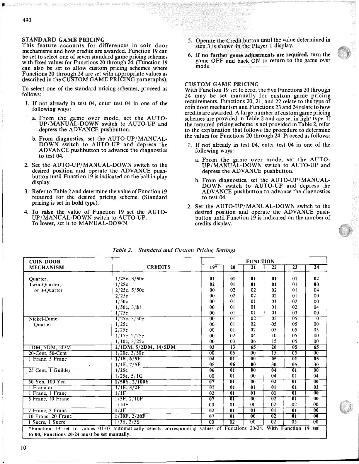
Table
2.
Standard
and
Custom Pricing Settings
COIN
DOOR
FUNCTION
MECHANISM
CREDITS
19·
20
21
22
23
24
Quarter,
1/25¢,3/50¢
01
01
01
01 01
02
Twin-Quarter,
1/25¢
02
01
01 01 01
00
or
3-Quarter
2/25et,5/50et
00
02
02
02
01
04
2/25et
00
02 02
02
01
00
1/50et
00
01
01
01
02 00
1/50et, 3/$1
00
01 01
01
02
04
1j75et
00
01
01
01
03
00
Nickel-Dime-
1/25et,3/50et 00
01
02
05
05
10
Quarter
1/25et
00
01
02
05
05
00
2/25et
00
01
02
05 05 05
I jl5et, 2/25et 00
02
04
10
05
00
I
jlOet,
3/25et 00
03
06
15
05 00
10M,
5DM,
2DM
2/lDM,
5/2DM,
14/5DM
03
13
65
26
05
65
20-Cent, 50-Cent I/
20et,3/50et
00
06 00
15
05
00
I Franc, 5
Franc
1/1t<, 6/51'
04
01
00
05
01
05
1/IF,7/5F
05 06
00
30
05
30
25
Cent, I
UUllde.r
1/25¢
06
01
00
04
01
00
1/25et,5j1G
00
01
00
04
01
04
50
Yen,
100
Yen
1/50Y,2/100Y
07
01
00
02
01
00
I
t'ranc
or
I/ll<,
j/Zl<
UI
01
01 01
01
02
I Franc, I
Franc
IflF
02
01
01 01 01
00
5 Franc,10Franc
1/5F,2/IOF
07
01
00
02
01
00
IjlOF
00
01
00
02
02
00
2 Franc, 2
Franc
1/2F
02
01
01 01
01
00
10
Franc,20Franc
1/10F,2/20F
07
01
00
02
01
00
I Sucre, I Sucre
1/3S,2/5S
00
02
00
02
05
00
*Function
19
set to values 01-07 automatically
selects
corresponding
values
of
Functions 20-24. With Function
19
set
to 00, Functions 20-24 must be set manually.
10
i
j
3.
Set
the
AUTO-UPjMANUAL-DOWN
switch
to
MANU
AL-DOWN
and
operate the Credit
button
until
00isindicated for
Function19on
the Player 1 display.
With
Function19setto00, Functions20
through
24 are
set
to
zero
and
now can be changed as required.
4.
RefertoTable 2oruse the explanation following this
procedure
and
determine
the
required
values
for
Functions 20
through
24.
5.
Set
the
AUTO-UPjMANUAL-DOWN
switch
to
AUTO-UP
and
momentarily depress the ADVANCE
pushbutton.
Function
20 should be
indicatedontheball
in play display.
6.
For
single chute coin doors, omit this step
and
leave the
value
of
00.
For
twinor3-chute coin doors, operate the
Credit
button
until
the
value
for
Function
20
determined in step 4
is
indicated in the Player 1 display.
7.
Momentarily
depress
the
ADVANCE
pushbutton.
Function21should be indicated
on
the ballinplay
display.
8.
For
twin chute coin doors, omit this step
and
leave the
value
of
00.
For
single
and
3 chute coin doors, operate
the Credit
button
until the value for
Function
21
determinedin step 4isindicated on the Player1display.
9.
Momentarily
depress
the
ADVANCE
pushbutton.
Function
22 should be indicatedonthe ball in play
display.
lO.
For
single chute coin doors omit this step
and
leave the
value
of
00.
For
twin or 3-chute coin doors, operate the
Credit
button
until
the
value
for
Function
22
determined in step 4
is
indicated on the Player1display.
11.
Momentarily
depress
the
ADVANCE
pushbutton.
Function23should be indicatedonthe ball in play
display.
12.
Operate the credit
button
untilthe valuefor
Function
23
determined in step 4isindicated in the Player 1 display.
13.
Momentarily
depress
the
ADVANCE
pushbutton.
Function 24 should be indicatedonthe ball in play
display.
14.
Omit this stepifno
bonus credits aretobe awarded for
inserting a certain value
of
coins. To award bonus
credits, operate the Credit
button
until the value for
Function
24 determined in step 4isindicatedonthe
Player
I display.
15.Ifno
other game adjustments aretobe made,
turn
the
game
OFF
and
back
ONtoreturn to the game over
mode.
PRICING
FORMULAS
There are five different functions usedtoset custom game
pricing. Three pertain
to
the coin
door
mechanism
and
the
other two determine how credits are awarded. Since there
are many combinations
of
coinvalues
and
coinmechanisms,
this explanation details how the functions relate
to
each
other
and
provides a generalized procedure for defining the
desired pricing scheme.
Proportional
values
are
assignedtoFunctions20, 21,
and
22
for the left (closest
to
hingeoncoin door), center,
and
right
coin chute, respectively.
Function
23
defines the valueofcoins required for a single
credit in relation
to
the
proportional
values assigned
to
functions 20, 21, and 22.
Function
24 permits awarding a
490
bonus credit for depositing some value
of
coin(s). A general
procedure follows:
1.
Determine
the
ratioofthe coin chute values by dividing
by
the largest
number
that
leaves a remainderofzero.
Examples:
25~ 25~
25~;
+
25=1:1:1
IDM
5DM
2DM;
+ 1 = 1:5:2
25~
-
IG;
+ 4 = 1:0:4
5~
lO~
25~;
+ 5 = 1:2:5
2.
Determing
the
valuesofFunctions20
through
24 is done
in one
of
two ways.
The
first method requires
that
bonus
credit
Function
24 be settozero.
The
second method
defines the
Function
24 value. Since some pricing
schemes may be implemented with either method, some
with only the first method,
and
others with only the
second method,
both
methods will havetobe tried in
some cases.
Both
methods use the ratio calculated in step1,the largest
numberofcredits defined in the pricing scheme,
and
the
numberofsmallest value coins requiredtoobtain
the largest
numberofcredits.
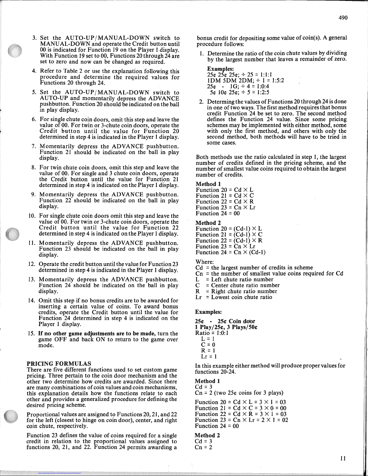
Method
1
Function
20 =
Cd
X L
Function21=
Cd
X C
Function
22 =
Cd
X R
Function23=
Cn
X Lr
Function
24 = 00
Method
2
Function
20 =
(Cd-I)
X L
Function21= (Cd-I) X C
Function
22 = (Cd-I) X R
Function23=
Cn
X Lr
Function
24 =
Cn
X (Cd-I)
Where:
Cd
= the largest
numberofcredits in scheme
Cn
= the numberofsmallest value coins required for
Cd
L = Left chute ratio
number
C = Center chute ratio
number
R = Right chute ratio
number
Lr
= Lowest coin chute ratio
Examples:
25¢ - 25¢ Coin
door
1
Play/25¢,
3 Plays/50¢
Ratio
= 1
:0:
1
L=1
C=O
R = 1
Lr
= 1
In
this example eithermethod will produce
proper
values for
functions 20-24.
Method
1
Cd
=3
Cn
= 2 (two
25~
coins for 3 plays)
Function
20 =
Cd
X L = 3 X 1 = 03
Function21=
Cd
X C = 3 X
().
= 00
Function
22 =
Cd
X R = 3 X 1 = 03
Function23=
Cn
X Lr = 2 X 1 = 02
Function
24 = 00
Method
2
Cd
=3
Cn
=2
11
490
Function
20
=(Cd-I) X L =(3-1) X 1 =02
Function
21
=(Cd-I) X C =
00
Function
22
=(Cd-I) X R =02
Function
23=CnXLr
=2 X 1 =
02
Function
24=Cn
X (Cd-I) =2 X (3-1) =2 X 2 =04
5¢
10¢ 25¢ Coin door
1 Play/15¢, 2 Plays/25¢
Ratio = 1:2:5
L=l
C=2
R = 5
Lr
= 1
In
this example, method 1 provides proper values
but
method 2 will not:
Method
1
Cd = 2
Cn
=5 (five 5¢ coins required for 2 plays)
Function
20=Cd
X L =2 X 1 =02
Function
21=Cd
X C =2 X 2 =04
Function
22=Cd
X R =2 X 5 =10
Function
23=CnXLr
=5 X 1 =
05
Function
24
=00
Method
2
Cd
=2
Cn
=5
Function
20
=(Cd-I) X L =(2-1) X 1 =
01
Function
21
=(Cd-I) X C =(2-1) X 2 =
02
Function
22
=(Cd-I) X R =(2-1) X 5 =
05
Function
23=CnXLr
=5 X 1 =
05
Function 24 =
Cn
X (Cd-I) =5 X (2-1) =
05
By
studying the values obtained in method 2 it will be
determined
that
the values setuppricing for 2 plays for 25¢
(no plays for 15¢). This example shows
that
some pricing
.schemes can be setupusing only oneofthe methods.
20¢ -
50t
Coin
door
1 Play/20¢, 3 Plays/SOt
Ratio = 2;0:5
L=2
C=O
R = 5
Lr
= 2
In
this example, only method 1 will produce proper values.
Method
1
Cd = 3
Cn
=2.5 (two
and
one-half
20¢
coin required for 3 plays)
Function
20=Cd
X L =3 X 2 =
06
Function
21=Cd
X C =3 X 0 =00
Function
22=Cd
X R =3 X 5 =
15
Function
23=CnXLr
=2.5 X 2 =
05
Function
24
=00
CREDITSINGAME
The humberofcreditsinthe game can be set to any number
from zero to99using Function 25. This allows for credits to
be entered into the gameorcredits to be removed. To
add
or
remove credits, proceed as follows:
1.
If
not
already in test 04, enter test 04 in oneofthe
following ways:
a.
From
the
game
over
mode,
set
theAUTO-
UP/MANUAL-DOWN
switch to AUTO-UP
and
depress the ADVANCE pushbutton.
12
lJ,Erom)diagll()~tics,
set the AUTO- UP/
MANU
AL-
PQWN
s
w
it
CllJ()
AUTO-UP
and
depress
the
ADVANCE
pushbuttontoadvance the diagnostics
to test 04.
2.
Set the
AUTO-UP/MANUAL-DOWN
switch to the
desired position and operate the ADVANCE pushbutton
until Function25is
indicatedonthe ball in play
display.
3.
To
add
credits, set the
AUTO-UP/MANUAL-DOWN
switch to AUTO-UP.
To remove credits, set it to MANUAL-DOWN.
4.
Operate the credit
button
until the desired number
of
creditsisindicated in the player 1 display.
5.Ifno
further game adjustments aretobe made,
turn
the
game
OFF
and back
ON
to return to the game over
mode.
HIGH
SCORE
CREDITS
Function26determines the numberofcredits to be awarded
when the current highest scoreisexceeded by a player. Note
that
the backup high score to date (Function 13) must be set
to some value other
than
zero for the high score feature to
operate. With Function26set to zero
and
Function13set to
any value other
than
zero, the high score to date feature will
still function
but
no credits will be awarded. To change the
numberofcredits for exceeding the high score, proceed as
follows:
1.
If
not
already in test 04, enter test04in oneofthe
following ways:
a.
From
the
game
over
mode,
set
theAUTO-
UP/MANUAL-DOWN
switch to AUTO-UP
and
depress the ADVANCE pushbutton.
b.
From
diagnostics, set the
AUTO-UP/MANUAL-
DOWN
switch
to
AUTO-UP
and
depress
the
ADVANCE pushbutton to advance the diagnostics
to
test
04.
2.
Set the
AUTO-UP/MANUAL-DOWN
switch to the
desired position
and
operate the ADVANCE push-
button
until Function26is indicatedonthe ballinplay
display.
3.
To increase the numberofcredits, set the AUTOUP/MANUAL-DOWN
switch to AUTO-UP.
To decrease the numberofcredits, set it to MANUALDOWN.
4.
Operate the credit
button
until the desired number
of
high score creditsisindicatedonthe player 1 display.
5.Ifno further game adjustments are required,
turn
the
game
OFF
and
back
ON
to return to the game over
mode.
PLAY
Function27controls game features for dropping all targets
in the 4-bank andfor droppingall targets in the right 3-bank.
The 4-bankofdroptargets advances lightingofthe eject hole
lamps towards a possible
Extra
Balland towards lightingthe
outlane rollovers for a possible SpeciaL The right 3-bank
advances lightingofthe captive ball,
bottom
jet bumpers,
spinners, and, for a possible Special, the right Bull's-Eye
target.
 Loading...