

Page 1

http://www.firepowerpinball.com
16P-497-103
Game No. 497
March, 1980
This booklet provides game operation, bookkeeping, game adjustment, and diagnostic procedures
for FIREPOWER. For installation and special maintenance information refer to the blue-covered
game manual. For detailed information refer to Williams Solid State Flipper Maintenance Manual.
SPECIAL CONSIDERATIONS WHEN REPLACING CIRCUIT BOARDS
CPU Board
1. Revision level 6 CPU Boards (batteries located on lower right corner of board) or later
boards must be used.
2. Must he equipped with green-labeled FIREPOWER PROMs, green-labeled game ROM and
green-labeled flipper ROMs.
3. Jumper J4 must be connected and J3 removed.
Sound Board
1. Model D 8224 required for speech.
2. Must be jumpered for white-labeled sound ROM operation and be equipped with Sound
ROM 3. (Jumpers W2, W5, W7, W9, W10, and W15 connected; W3, W4, W6, W8, W11,
W12, and W13 removed)
Power Supply Board
1. Fuse F4 (10A SB) for flipper solenoids must be installed.
Optional Speech Module
1. Requires 5T4971 (IC7), 5T4972 (IC5), and ST4973 (IC6) speech ROMs.
GAME OPERATION
*Indicates adjustable features
Game Over Mode - Turn game ON; player scores show zero, high score to date* alternates with
player I score, player I up lamp flashes, game over lamp lights, all playfield lamps except for
credit lamp cycle in attract mode.
Credit Posting - Insert coin; knocker sounds, number of credits displayed. If maximum credits*
exceeded by coin or high score to date*, credits are posted correctly, coin lockout deenergized
until remaining credits are below maximum. No credits may be won and coins are rejected while
lockout is deenergized.
Game Start - Push credit button; start-up tune played, ball served, credit display reduced by one,
player I up lamp flashes until first scoring switch is made, ball in play shows 1. Pushing credit
button before ball 2 displayed allows additional players.
MULTI-BALL and LANE CHANGE are trademarks of Williams Electronics, Inc.
Page 2

http://www.firepowerpinball.com
Bonus Advance - "F-l-R-E" rollovers when not lit, flashing "1-6" targets, left and right inside rollovers (3
advances when lit), and left and right outside rollovers. Bonus multiplier advanced and FIRE insert lit by
spotting "F-l-R-E". "F-l-R-E" lamps rotate by actuating right flipper (LANE CHANGE™ feature).
FIREPOWER - Making three POWER targets scores 10,000 and lites POWER insert, left and right inside
rollovers, and *ball saver kicker ON. Liting FIRE and POWER inserts scores and advances FIREPOWER
bonus (5,000 or lit values of 10, 30, and 50,000). Outlane Special lit when *30, or 50,000 bonus collected.
"1-6" Targets - *Making "1-3" or "4-6" or same ball lights ball saver kicker ON. Spotting "1-6" lights ball
saver kicker ON*, flashes two eject holes, lights spinner, and alternately lights two jet bumpers; ad justable
to flash eject holes one at a time (always one at a time once MULTI-BALL play is achieved). Spotting "1-6"
twice on the same ball lights all jet bumpers.
Eject Holes - Making eject hole when flashing locks up ball and new ball released per following order: from
ball ramp, flashing eject hole, unlit eject hole. Locking up all balls in eject holes initiates MULTI-BALL
play. To minimize multiple player interaction, lit and flashing eject holes are reallocated from ball to ball as
required: Dashing lamp to empty eject hole if possible; lit lamp to occupied eject hole if possible.
Extra Ball - Maximum of two Extra Balls per ball. Lighting *5x or making"F-I-R-E" with 5x lit lights center
POWER target for Extra Ball. Making target when lit awards Extra Ball.
Tilts - Ball in play tilted on first closure of Playfield and Ball Roll tilts and third* closure of Plumb Bob.
Slam Tilt returns game to game over.
Memory - "F-l-R-E" lanes, FIRE insert, POWER Target lamps, POWER insert, *FIREPOWER bonus lamps,
*lit target arrows, eject hole lamps.
End of Game - Match Digits* appears in ball in play display, *credit awarded for match. Exceeding high
score to date awards *three credits. Match, High Score to Date, and Game Over sounds made as appropriate.
Balls released from eject holes and are placed on ball ramp before new game can be started.
With optional Speech Module, the following phrases are produced during game play:
ACHIEVEMENT
Game start, collecting FIREPOWER bonus
Making "F-l-R-E"
Lighting POWER
Spotting "1-6" lamps
MULTI-BALL play
Winning Extra Ball
Making Special
Tilt
High Score to Date
Game Over Random Phrase
You destroyed FIREPOWER.
Enemy destroyed you.
Mission 213 accomplished.
You are enemy.
Enemy fire destroyed you.
Fire destroyed you.
BOOKKEEPING AND EVALUATION TOTALS
(Functions 01-12)
1. In game over mode, set alternate-action switch to AUTO- UP (out) and depress ADVANCE pushbutton. Test
04 is indicated in number of credits display, Function 00 in ball in play display, and game identification in
Player 1 display.
PHRASE
FIREPOWER.
FIRE.
POWER.
Enemy destroyed.
Fire 1, 2, 3.
You won one mission.
Mission accomplished.
You are destroyed.
FIREPOWER mission accomplished.
Mission destroyed you.
Enemy power won.
You destroyed enemy mission.
Enemy mission.
You won, FIREPOWER destroyed.
FIREPOWER destroyed.
2
Page 3

http://www.firepowerpinball.com
2. Operate the ADVANCE pushbutton to display each function on the ball in play display (see Table 1) and
record each total from Player I display. (To reveiw a total that has been advanced past, set alternate-action
switch to MANUAL-DOWN (in) and operate the ADVANCE pushbutton.)
3. Calculate the following if desired:
% Paid Credits = Function 04 Function 08
4. Turn the game OFF and back ON to return to game over mode.
5. To change current High Score to Date to value of Function 13, momentarily depress HIGH SCORE
RESET pushbutton.
6. To zero Functions 01-11, see page 7
GAME ADJUSTMENT PROCEDURE
( Functions 13-35)
Coin door must be open to change settings.
1. In game over mode, set alternate-action switch to AUTO- UP (out) and depress ADVANCE pushbutton.
Test 04 is indicated in number of credits display, Function 00 in ball in play display, and game identification
in Player I display.
2. To raise Function number in ball in play display, operate ADVANCE pushbutton with switch set to
AUTO-UP (in). To lower Function number operate ADVANCE with it set to MANUAL-DOWN (out).
3. With desired Function indicated in ball in play display, raise value in player 1 display by operating credit button
with switch set to AUTO-UP (out); lower value by operating credit button with it set to MANUAL-DOWN (in).
Value left of Player I display is new setting. For values see Table I and (for pricing) Table 2.
4. Repeat steps 2 and 3 until all required adjustments have been made.
5. Turn game OFF and back ON to return to game over mode.
6. To restore factory settings and zero audit totals, see page 7.
DIAGNOSTIC PROCEDURES
(Display Digits, Lamp. Solenoid. and Switch Tests)
1. In game over mode, set alternate-action switch to MANUAL-DOWN (in) and depress ADVANCE. All
displays should go blank.
2. Momentarily depress ADVANCE and set switch to AUTO-UP (out). Display Digits test is performed.
3. Momentarily depress ADVANCE. Test 01 is indicated on number of credits display an Lamp Test is
performed.
4. Set switch to MANUAL-DOWN (in) and momentarily depress ADVANCE. Test 02 is indicated on number
of credits display and solenoid 01 on the ball in play display; solenoid 01 is pulsed by driver board.
5. Operate ADVANCE to pulse each solenoid (see Figure 3). Pulse solenoid 08 three times to remove balls
from ramp before proceeding to switch test.
6. Set switch to AUTO-UP (out) and momentarily depress ADVANCE. Test 03 is indicated on number of
credits display and stuck switches on ball in play display.
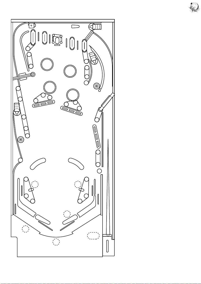
7. See Figure 4. Operate switches; switch number is indicated on ball in play display.
8. Turn game OFF and back ON to return to game over mode.
9. To set up Auto-Cycle Mode (Display Digits, Lamp, and Solenoid Tests) see page 7.
3
Page 4
http://www.firepowerpinball.com
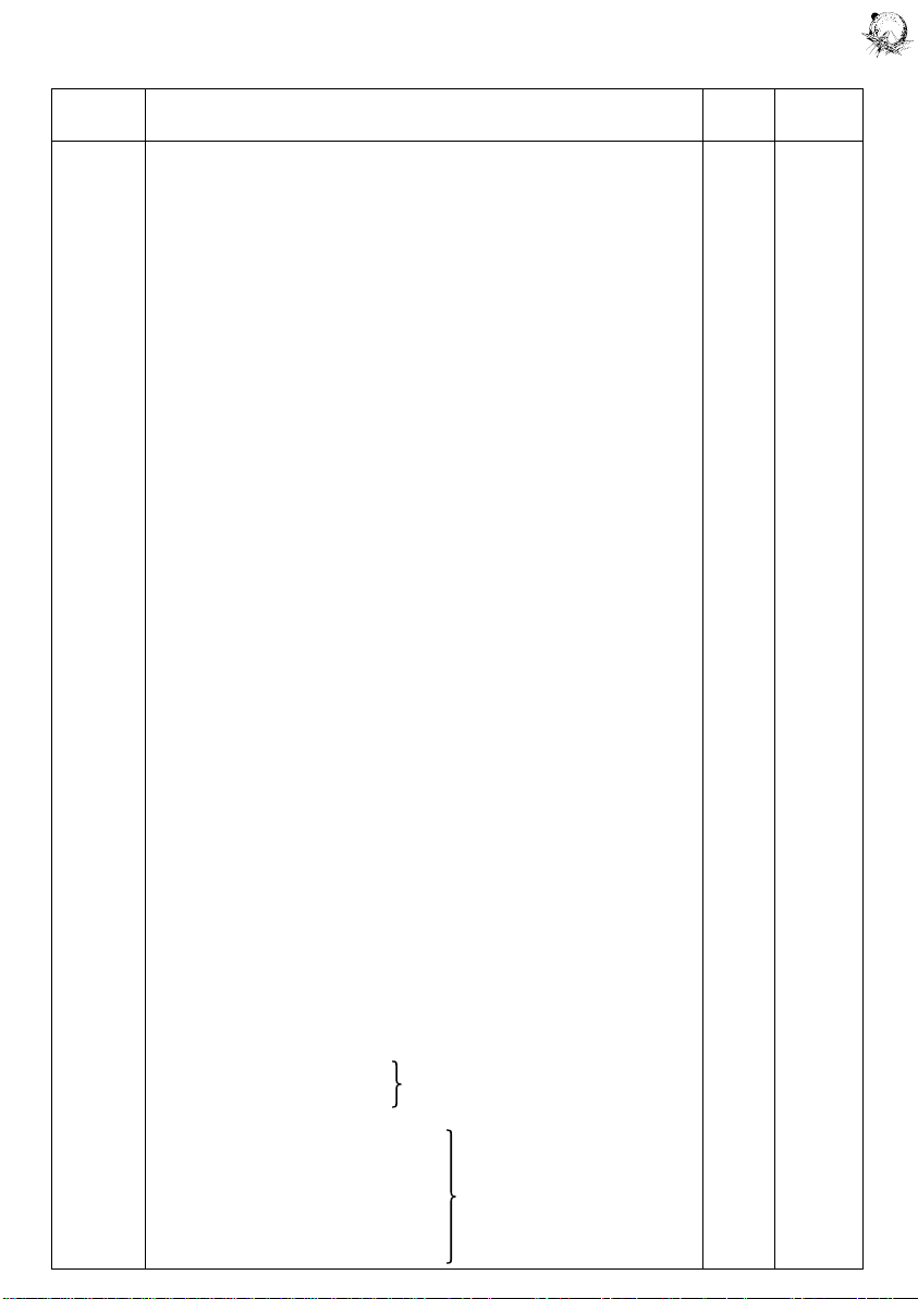
Table 1. Game Adjustments
FACTORY
FUNCTION DESCRIPTION NOTES SETTING
00 Game Identification 1 1497 2
01 Coins, Left Chute (Closest to coin door hinge) 1 –
02 Coins, Center Chute 1 –
03 Coins, Right Chute 1 –
04 Total Paid Credits 1 –
05 Total Specials 1 –
06 Total Replay (Extra Ball) Scores 1 –
07 Match and High Score to Date Credits 1 –
08 Total Credits 1, 2 –
09 Total Extra Balls 1, 3 –
10 Total Ball Time in Minutes 1 –
11 Total Number of Balls Played 1 –
12 Current High Score to Date 4 550,000
13 Backup High Score to Date 5 550,000
14 Replay 1 Score 6 410,000
15 Replay 2 Score 6 610,000
16 Replay 3 Score 6 0
17 Replay 4 Score 6 0
18 Maximum Credits 7 20
19 Standard and Custom Pricing Control (00-07) 8 02
20 Left Coin Slot Multiplier 8 01
21 Center Coin Slot Multiplier 8 04
22 Right Coin Slot Multiplier 8 01
23 Coin Units Required for Credit 8 01
24 Coin Units Bonus Points 8 00
25 High Scores Credits 5 03
26 Match (00=ON 01=OFF) – 00
27 Special – 00
0 = Awards Credit
01 = Awards Extra Ball
02 = Awards Points
28 Scoring Awards – 00
00 = Credits at Replay Score
01 = Extra Ball at Replay Score
29 Maximum Plumb Bob Tilts (1-9) – 03
30 Number of Balls (03 or 05) 9 03
31 "1-6" Targets 9 03
00 = Eject Holes lit singly, no target memory
01 = Eject Hole pair lit first time, no target memory
02 = Eject Holes lit singly, targets on memory
03 = Eject Hole pair lit first time, targets on memory
32 Ball Saver Kicker ON Lamp – 01
00 = Lit from POWER Targets
01 = Lit from "1-3" or "4-6" targets on same ball or spotting "1-6" lamps
02 = Lit from "1-6" lamps
03 = Lit from "1-6" Lamps or POWER targets
33 FIREPOWER Bonus Lamps – 03
00 = No lamps lit initially, no lamp memory (extra conservative)
01 = 10,000 lamp lit initially, no lamp memory (conservative)
02 = No Lamps lit initially, bonus lamps on memory (moderate)
03 = 10,000 lamp lit initally, bonus lamps on memory (liberal)
34 Extra Ball Control/Attract Mode Sounds – 01
00/01 = No Extra Ball
01/11 = Extra Ball when Lit after 5X
02/12 = Extra Ball when Lit with 5X
35 Special Control/Background Sound – 12
00/10 = Alternating Special lites when 50,000
FIREPOWER Bonus collected
01/11 = Alternating Special lites when 30,000
FIREPOWER Bonus collected
02/12 = Special lite when 50,000
FIREPOWER Bonus collected
03/13 = Specials lite when 30,000
FIREPOWER Bonus collected
1st setting = No Attract Mode Sounds
2nd setting = Attract Mode Sounds
1st setting =
no background sound
2nd setting =
background sound on
4
Page 5

http://www.firepowerpinball.com
Notes:
1. Functions 00- 11 cannot be changed from the coin door; however, Functions 01-11 can be set to zero as
described on page 7.
2. Total Credits (Function 08) is the sum of Function 04 and as applicable, Functions 05, 06, and 07.
3. Total Extra Balls (Function 09) is the sum of the game extra ball feature and Functions 15 and 06, as
applicable.
4. Current High Score to Date (Function 12) can be changed to the value of the Backup High Score to Date
(Function 13) by operating the HIGH SCORE RESET switch while in the game over mode.
5. Function 13 may be set to any multiple of 10,000 points. Setting Function 25 to zero with Function 13 set
to any score but zero permits the High Score to Date feature to operate but no credits are awarded.
6. Functions 14-17 (Replay Scores) may be set to any multiple of 10,000 points. Setting a function to zero
disables the replay score point. Always disable the Replay 4 level first, the Replay 3 level second,
etc. The replay levels must be set with ascending values.
7. Setting Maximum Credits (Function 18) to zero places the game in a free play mode.
8. With Function 19 set to 00, Functions 20-24 must be set manually. Refer to Table 2 for seven standard
pricing schemes (selected by values of 01-07 for Function 19) and custom pricing values.
9. For 5-Ball play, it is recommended that Function 31 be set to 02.
RECOMMENDED SCORE LEVELS
Levels Score Card
CREDIT GAMES
3-Ball:
*410,000; 610,000 497-36
or 410,000; 620,000; 740,000 497-14
5-Ball:
(See Note 9)
500,000; 720,000 497-45
EXTRA BALL
3-Ball:
300,000 497-74
5-Ball:
400,000 497-76
* Factory Setting
5
Page 6
http://www.firepowerpinball.com
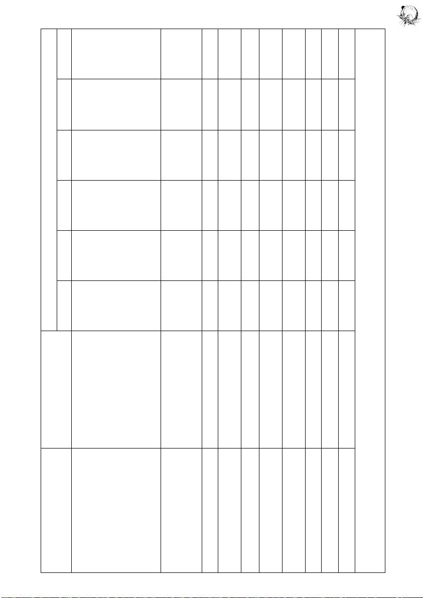
Table 2. Standard and Custom Price Settings
COIN DOOR FUNCTION
MECHANISM CREDITS 19 20 21 22 23 24
Twin-Quarter 1 / 25¢, 3 / 50¢, 7 / $1 00 03 12 03 02 12
Quarter, Dollar, Quarter 1 / 25¢, 3 / 50¢, 7 / $1 coin only 00 03 14 03 02 00
1 / 25¢, 7 / $1 coin only 00 01 07 01 01 00
1 / 25¢, 3 / 50¢, 6 / $1 00 01 04 01 01 02
1 / 25¢, 6 / $1 coin only 00 01 06 01 01 00
• 1 / 25¢, 5 / $1 05 01 04 01 01 04
1 / 25¢, 5 / $1 coin only 00 01 05 01 01 00
• 1 / 25¢, 4 / $1 02 01 04 01 01 00
• 1 / 25¢, 3 / $1 01 01 04 01 02 04
1 / 50¢ 00 01 04 01 02 00
1DM, 5DM, 2DM • 1 / 1DM, 3 / 2DM, 10 / 5DM 03 09 45 18 05 45
2 / 1DM, 5 / 2DM, 14 / 5DM 00 13 65 26 05 65
20-Cent, 50-Cent 1 / 20¢, 3 / 50¢ 00 06 00 15 05 00
1 Franc, 10 Franc, 5 Franc • 1 / 2F, 3 / 5F only, 8 / 10F only 04 01 16 06 02 00
25 Cent, • 1 / 25¢, 4 / 1G 06 01 00 04 01 00
1 Guilder 1 / 25¢, 5 / 1G 00 01 00 04 01 04
50 Yen, 100 Yen • 1 / 50Y, 2 / 100Y 07 01 00 02 01 00
1 Franc or 1 / 1F, 3 / 2F 00 01 01 01 01 02
Twin-1 Franc 1 / 1F 00 01 01 01 01 00
5 Franc, • 1 / 5F, 2 / 10F 07 01 00 02 01 01
10 Franc 1 / 10F 00 01 00 02 02 00
Twin-2 Franc • 1 / 2F 02 01 04 01 01 00
10, 20 Franc • 1 / 10F, 2 / 20F 07 01 00 02 01 00
Twin-1 Sucre 1 / 3S, 2 / 5S 00 02 00 02 05 00
• Indicates standard price settings by adjusting only Function 19. For other price settings, set Function 19 to 00 and set Functions 20
through 24 to the values indicated in the chart.
6
Page 7
http://www.firepowerpinball.com
RESETTING AUDIT TOTALS AND ADJUSTMENTS;
INITIATING AUTO-CYCLE MODE
1. In game over mode, set the alternate-action switch to MANUAL-DOWN (in) and momentarily depress the
ADVANCE pushbutton. All displays should go blank.
2. Remove the backglass and unlatch and open the insert door.
3. Set all switches on the MASTER COMMAND slide switch to OFF (move to the right).
4. Set switch on MASTER COMMAND switch to ON (move to left):
a. To zero audit totals (Functions 01-11) set switch 8 to ON.
b. To restore factory settings and zero audit totals, set switch 7 to ON. Coin Door must remain open to
restore factory settings.
c. For Auto-Cycle Mode set switch 6 to ON.
5. Momentarily depress MASTER COMMAND ENTER pushbutton. The LEDs should blink once.
6. a. After zeroing audit totals turn game OFF and ON to return to game over mode.
b. After restoring factory settings, turn game OFF and ON twice to return to game over mode.
c. To initiate Auto-Cycle Mode, set alternate-action switch to AUTO-UP (out) and momentarily depress the
ADVANCE pushbutton. Each cycle of this mode sequences through display digits test, flashes all
multiplexed lamps 64 times and pulses each solenoid. To terminate the Auto-Cycle mode and go to game
over, turn the game OFF and ON.
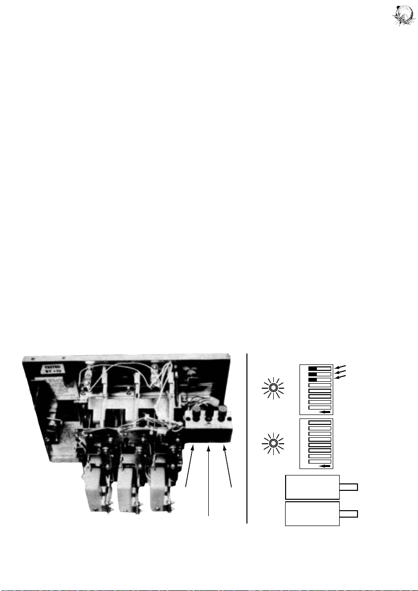
Figure 1. Coin Door Diagnostic Switches
HIGH
SCORE
RESET
AUTO-UP
MANUAL-DOWN
ADVANCE
MAST E R COMM A ND
LED
LED
1 2 3 4 5 6 7 8
N
O
1 2 3 4 5 6 7 8
N
O
MAST E R
COMM A N D
ENTE R
DIAG N O STIC
Figure 2.
Master Command
Settings Switch
ZERO AUDIT TOTALS
RESTORE FACTORY SETTINGS
AUTO-CYCLE MODE
NOT USED
7
Page 8
http://www.firepowerpinball.com
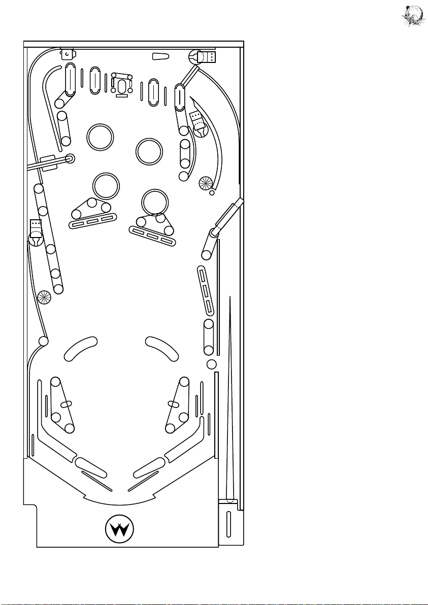
06
NO. DESCRIPTION
01 Ball Release
02 Not Used
03 Not Used
04 Left Eject Hole
05 Right Eject Hole
06 Upper Right Eject Hole
SOL.
17
19
05
07 Left Ball Saver Kicker
08 Ball Ramp Thrower
09 Sound
10 Sound
18
20
11 Sound
12 Sound
13 Sound
14 Credit Knocker
15 Flash Lamps
16 Coin Lockout
17 Top Left Jet Bumper
04
18 Bottom Left Jet Bumper
19 Top Right Jet Bumper
20 Bottom Right Jet Bumper
21 Right Kicker
22 Left Kicker
15
07
01
15
2122
08
Figure 3. Playfield Solenoid Locations and Solenoid Chart
8
Page 9
http://www.firepowerpinball.com
Table 3. Solenoid Connections
SOL. WIRE DRIVER SOLENOID
NO. FUNCTION COLOR CONNECTIONS TRANS. PART NO.
01 Ball Release GRY-BRN 2P11-4, 8P3-17 Q15 SA-23-850-DC
02 Not Used GRY-RED 2P11-5, 8P3-18 Q17 —
03 Not Used GRY-ORN 2P11-7, 8P3-19 Q19 —
04 Left Eject Hole GRY-YEL 2P11-8, 8P3-20 Q21 SG-23-850-DC
05 Right Eject Hole GRY-GRN 2P11-9, 8P3-21 Q23 SG-23-850-DC
06 Upper Right Eject Hole GRY-BLU 2P11-3, 8P3-22 Q25 SG-23-850-DC
07 Left Ball Saver Kicker GRY-VIO 2P11-2, 8P3-23 Q27 SG-23-850-DC
08 Ball Ramp Thrower GRY-BLK 2P11-1, 8P3-24 Q29 SA-23-850-DC
09 Sound BRN-BLK 2P9-9, 10P3-3 Q31 —
10 Sound BRN-RED 2P9-7, 10P3-2 Q33 —
11 Sound BRN-ORN 2P9-1, 10P3-5 Q35 —
12 Sound BRN-YEL 2P9-2, 10P3-4 Q37 —
13 Sound BRN-GRN 2P9-3, 10P3-7 Q39 —
14 Credit Knocker BRN-BLU 2P9-4, 7P1-16 Q41 SA2-23-850-DC
15 Flash Lamps BRN-VIO 2P9-5, 6P2 Q43 Type 89 Bulbs
16 Coin Lockout BRN-GRY 2P9-6, 7P1-18, 7P2-4 Q45 SM-35-4000-DC
*17 Top Left Jet Bumper BLU-BRN 2P12-7, 8P3-11 Q2 SG-23-850-DC
*18 Bottom Left Jet Bumper BLU-RED 2P12-4, 8P3-12 Q4 SG-23-850-DC
*19 Top Right Jet Bumper BLU-ORN 2P12-3, 8P3-13 Q6 SG-23-850-DC
*20 Bottom Left Jet Bumper BLU-YEL 2P12-6, 8P3-14 Q8 SG-23-850.DC
*21 Right Kicker BLU-GRN 2P12-8, 8P3-15 Q10 SG-23-850-DC
*22 Left Kicker BLU-BLK 2P12-9, 8P3-16 Q12 SG-23-850-DC
* Right FLipper BLU-VIO 7P1-8, 8P3-3 — SFL-19-400/
— 30-750-DC
* Left Flipper BLU-GRY 7P1-10, 8P3-4 — SFL-19-400/
— 30-750-DC
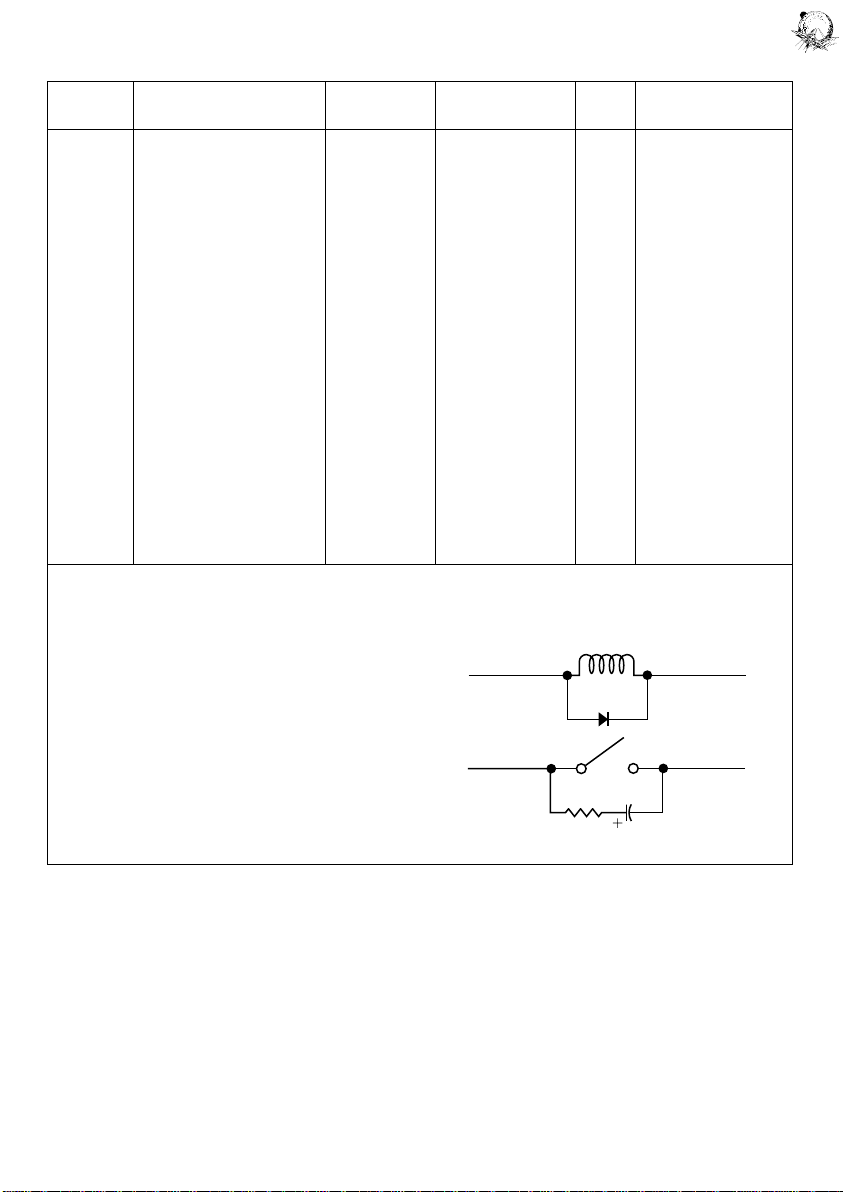
*NOTES:
1. Special switch connections for solenoids 17 through 22
are as follows:
17 — ORN-BRN — 2P13-5, 8P3-5
18 — ORN-RED — 2P13-3, 8P3-6
19 — ORN-BLK — 2P13-2, 8P3-7
20 — ORN-YEL — 2P13-4, 8P3-8
21 — ORN-GRN — 2P13-8, 8P3-9
22 — ORN-BLU — 2P13-9, 8P3-10
2. Flipper button connections are as follows:
Right — ORN-VIO — 2P12-1, 7P1-7
Left — ORN-RED — 2P12-2, 7P1-9
3. Typical wiring for solenoids and special switches:
RED (B+)
BLK (GRD)
9
Page 10
http://www.firepowerpinball.com
SWITCH
32
33
16
34
29
36
35
31
NO. FUCTION (SCORE)
01 Plumb Bob Tilt
02 Ball Roll Tilt
03 Credit Button
04 Right Coin Switch
05 Centre Coin Switch
06 Left Coin Switch
07 Slam Tilt
08 High Score Reset
26
27
15
25
14
28
30
37
54
09 Outhole
10 Left Outside Rollover (1000)
11 Left Inside Rollover (1000/3000)
12 Left Kicker (10)
13 Left Eject Hole (1000/10,000)
14 Upper Middle Left Standup (50)
15 Spinner (100/1000)
16 Top Left Standup (50)
17 "1" Target (1000)
18 "2" Target (1000)
19 "3" Target (1000)
49
13
50
53
19
18
17
21
22
23
38
39
40
41
20 Not Used
21 "4" Target (1000)
22 "5" Target (1000)
23 "6" Target (1000)
24 Not Used
25 Bottom Left Jet Bumper (100/1000)
26 Top Left Jet Bumper (100/1000)
27 Top Right Jet Bumper (100/1000)
28 Bottom Right Jet Bumper (100/1000)
29 Top Centre Target (1000)
30 Right Eject Hole (1000/10,000)
31 Upper Top Right Standup (50)
32 "F" Rollover (1000)
48
33 "I" Rollover (1000)
34 "R" Rollover (1000)
35 "E" Rollover (1000)
36 Upper Right Eject Hole (1000/10,000)
37 Lower Top Right Standup (50)
11
12
43
42
38 Middel Right Standup (50)
39 Top "POWER" Target (1000)
40 Middle "POWER" Target (1000)
41 Bottom "POWER" Target (1000)
42 Right Kicker (10)
43 Right Inside Rollover (1000/3000)
44 Right Outside Rollover (1000)
45 Right Flipper LANE CHANGE Switch
10
45
44
46 Ball Shooter
47 Playfield Tilt
48 Lower Right Standup (50)
49 Centre Middle Left Standup (50)
50 Lower Middle Left Standup (50)
51 Left Ball Ramp
47
515857
09
46
52 Not Used
53 Left Eject Rollover (1000)
54 Right Eject Rollover (1000)
55 Not Used
56 Not Used
57 Right Ball Ramp
58 Centre Ball Ramp
NOTE: Second score is lit or flashing value.
10
Figure 4. Playfield Switch Locations and Switch Chart
Page 11
http://www.firepowerpinball.com
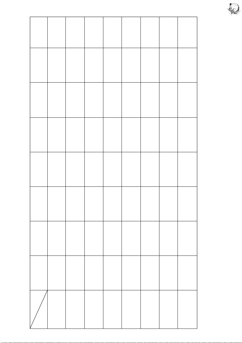
Figure 6. Switch Matrix
1 9 17 25 33 41 49 57
COLUMN 1 2 3 4 5 6 7 8
ROW GRN-BRN GRN-RED GRN-ORN GRN-YEL GRN-BLK GRN-BLU GRN-VIO GRN-GRY
1 WHT- PLUMB OUTHOLE "1" BOTTOM "I" BOTTOM CENTRE RIGHT
BRN BOB TARGET LEFT JET ROLLOVER "POWER" MIDDLE LEFT BALL
TILT BUMPER TARGETS STANDUP RAMP
2 WHT- BALL LEFT OUTSIDE "2" TOP "R" RIGHT LOWER CENTRE
RED ROLL ROLLOVER TARGET LEFT JET ROLLOVER KICKER MIDDLE LEFT BALL
TILT BUMPER STANDUP RAMP
2 10 18 26 34 42 50 58
3 WHT- CREDIT LEFT INSIDE "3" TOP "E" RIGHT INSIDE LEFT NOT
3 11 19 27 35 43 51 59
ORN BUTTON ROLLOVER TARGET RIGHT JET ROLLOVER ROLLOVER BALL USED
BUMPER RAMP
4 WHT- RIGHT LEFT NOT BOTTOM UPPER RIGHT OUTSIDE NOT NOT
YEL COIN KICKER USED RIGHT JET RIGHT EJECT ROLLOVER USED USED
SWITCH BUMPER HOLE
4 12 20 28 36 44 52 60
5 WHT- CENTRE LEFT "4" TOP CENTRE LOWER RIGHT FLIPPER LEFT EJECT NOT
GRN COIN EJECT HOLE TARGET TARGET TOP RIGHT LANE CHANGE ROLLOVER USED
SWITCH STANDUP SWITCH
5 13 21 29 37 45 53 61
6 14 22 30 38 46 54 62
6 WHT- LEFT UPPER "5" RIGHT MIDDLE BALL RIGHT EJECT
BLU COIN MIDDLE LEFT TARGET EJECT HOLE RIGHT SHOOTER ROLLOVER NOT
SWITCH STANDUP STANDUP USED
7 WHT- SLAM SPINNER "6" UPPER TOP TOP PLAYFIELD NOT NOT
VIO TILT TARGET RIGHT "POWER" TILT USED USED
STANDUP TARGET
7 15 23 31 39 47 55 63
8 WHT- HIGH TOP LEFT NOT "F" MIDDLE LOWER NOT NOT
GRY SCORE STANDUP USED ROLLOVER "POWER" RIGHT USED USED
RESET TARGET STANDUP
8 16 24 32 40 48 56 64
11
Page 12
http://www.firepowerpinball.com
12
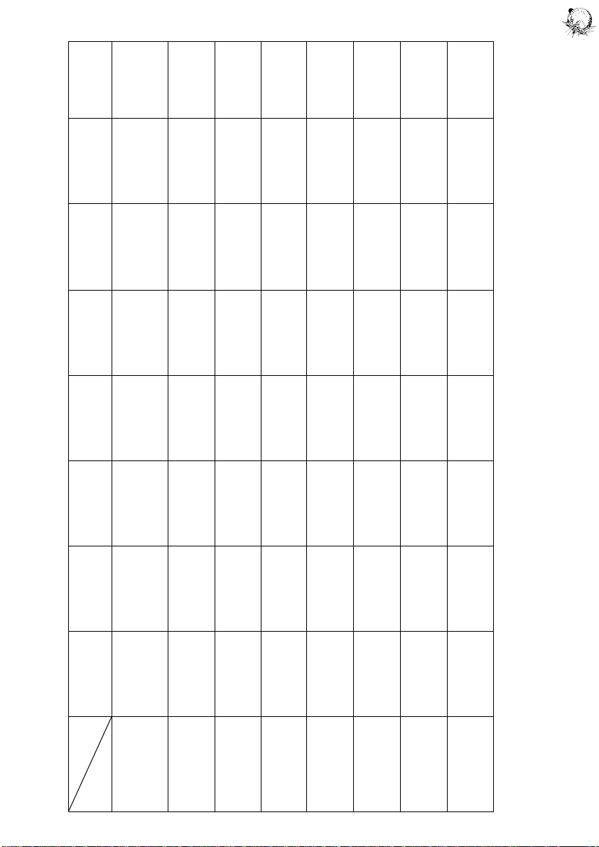
Figure 6. Lamp Matrix
COLUMN 1 2 3 4 5 6 7 8
ROW YEL-BRN YEL-RED YEL-ORN YEL-BLK YEL-GRN YEL-BLU YEL-VIO YEL-GRY
1 RED- SAME PLAYER TOP 4,000 20,000 LEFT 10,000 RIGHT #1
BRN SHOOTS POWER BONUS BONUS EJECT HOLE FIREPOWER SPECIAL PLAYER
AGAIN TARGET ARROW BONUS UP
(PLAYFIELD)
2 RED- BALL CENTRE 5,000 "1" RIGHT 30,000 1 #2
BLK SAVER POWER BONUS TARGET EJECT HOLE FIREPOWER CAN PLAYER
KICKER ON TARGET ARROW ARROW BONUS PLAY UP
3 RED- FIRE BOTTOM 6,000 "2" UPPER RIGHT 50,000 2 #3
ORN (x2) POWER BONUS TARGET EJECT HOLE FIREPOWER CAN PLAYER
TARGETS ARROW ARROW BONUS PLAY UP
4 RED- POWER RIGHT 7,000 "3" 2X TOP 3 #4
YEL (x2) INSIDE BONUS TARGET LEFT JET CAN PLAYER
ROLLOVER ARROW BUMPER PLAY UP
5 RED- "F" LEFT 8,000 "4" 3X TOP 4 TILT
GRN INSIDE BONUS TARGET RIGHT JET CAN
ROLLOVER ARROW BUMPER PLAY
6 RED- "I" 1,000 9,000 "5" 4X BOTTOM MATCH GAME
BLU BONUS BONUS TARGET RIGHT JET OVER
ARROW BUMPER
7 RED- "R" 2,000 NOT "6" 5X BOTTOM BALL SAME PLAYER
VIO BONUS USED TARGET LEFT JET IN SHOOTS
ARROW BUMPER PLAY AGAIN
8 RED- "E" 3,000 10,000 SPINNER EXTRA BALL LEFT
GRY BONUS BONUS 1,000 WHEN LIT SPECIAL CREDITS HIGH SCORE
WHEN LIT (PLAYFIELD) TO DATE
 Loading...