

Page 1
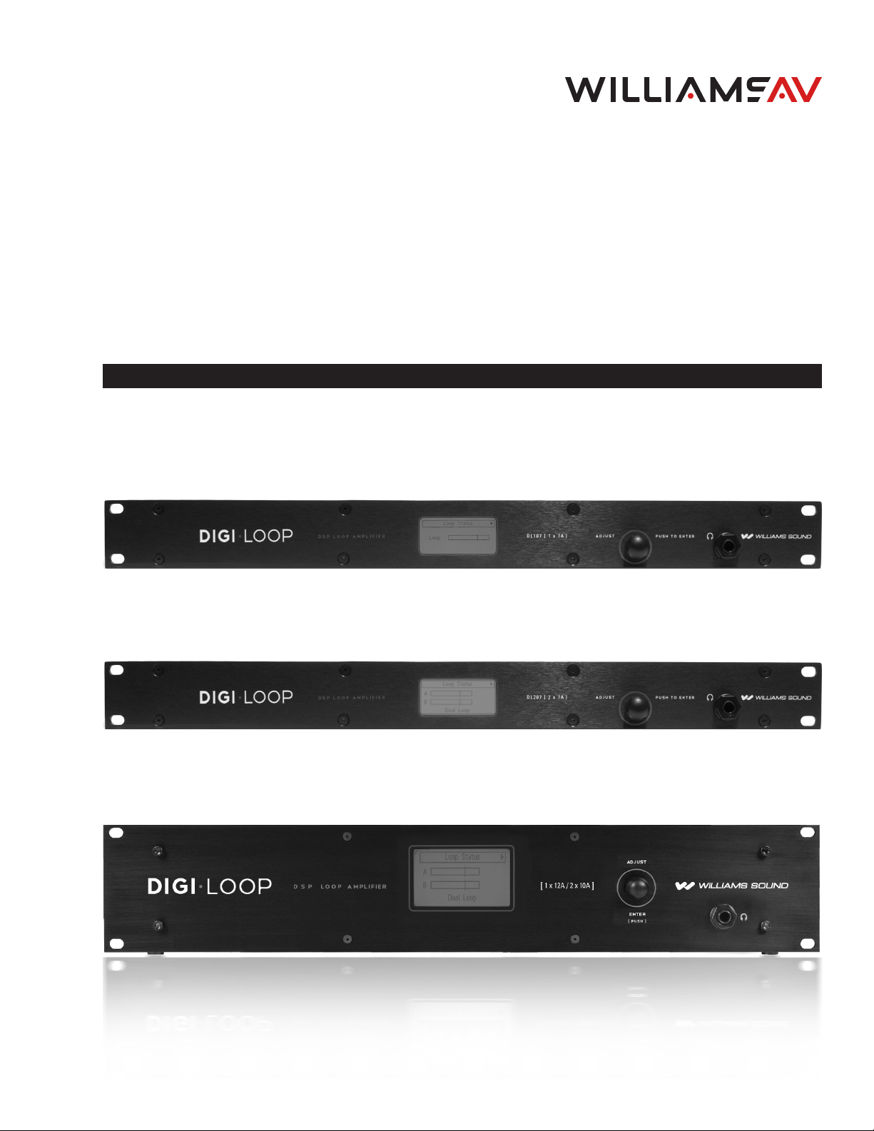
DL107 NET, DL107 NET D
DL207 NET, DL207 NET D
DL210 NET 2.0, DL210 NET D 2.0
Digi-Loop® DSP Induction Loop Amplifiers
DL107 NET, DL107 NET D
INSTALLATION MANUAL
DL207 NET, DL207 NET D
DL210 NET 2.0, DL210 NET D 2.0
MAN 202M
Page 2

DL107, DL207 and DL210 2.0 Digi-Loop™ DSP Induction Loop Amplifiers
Table of Contents
Safety Warnings and Instructions 4
Avertissements et instructions de sécurité 5
How to Read this Manual 6
Amplier Overview 6
Main Features (these vary by model) 7
Getting started: Connecting the amplier 8
Rear connectors ................................................................................................................................................................................................................9
Rack Installation .............................................................................................................................................................................................................. 10
Ethernet Wiring ................................................................................................................................................................................................................ 10
Using the Dante Audio Input ........................................................................................................................................................................................ 11
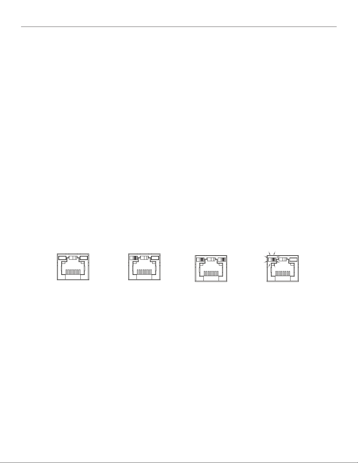
Dante jack LED indication (this diers from standard ethernet). ......................................................................................................................... 11
Analog Audio Input Connections ............................................................................................................................................................................... 12
Loop Fault Relay Overview .......................................................................................................................................................................................... 12
DL107/207 Loop Fault Relay Connections ................................................................................................................................................................13
DL210 2.0 Loop Fault Relay connections ..................................................................................................................................................................13
Loop Wire Selection ........................................................................................................................................................................................................13
Powering Up .....................................................................................................................................................................................................................14
Initial Conditions ...............................................................................................................................................................................................................14
Loop Termination Warnings ..........................................................................................................................................................................................14
Checking and updating rmware 15
To check the firmware version on the amplifier: .................................................................................................................................................... 15
To update the firmware on the amplifier: ................................................................................................................................................................. 15
Installing and conguring the PC App 16
Ethernet Control Setup ..................................................................................................................................................................................................17
USB Control Setup ......................................................................................................................................................................................................... 18
Calibrating & commissioning the loop amplier 19
Appendices 23
Maintenance & cleaning .............................................................................................................................................................................................. 23
General Troubleshooting ............................................................................................................................................................................................. 23
Troubleshooting a firmware update failure ............................................................................................................................................................. 23
PC App Detail ................................................................................................................................................................................................................. 24
Front LCD Menu ............................................................................................................................................................................................................. 29
Specifications ...................................................................................................................................................................................................................37
Resources ........................................................................................................................................................................................................................ 39
Warranty 39
2
Page 3

DL107, DL207 and DL210 2.0 Digi-Loop™ DSP Induction Loop Amplifiers
Williams AV recommends that this equipment be installed by a qualified
installer.
This is a person who has taken an Advanced Loop Class.
We recommend the Williams AV Advanced Loop Class, because it
includes specific information about Williams AV Loop Amplifiers in the
designing, installing and commissioning of loop systems.
3
Page 4
DL107, DL207 and DL210 2.0 Digi-Loop™ DSP Induction Loop Amplifiers
Safety Warnings and Instructions
WARNING! TO REDUCE THE RISK OF FIRE OR ELECTRIC SHOCK, DO
NOT EXPOSE THIS APPLIANCE TO RAIN OR MOISTURE.
CAUTION! TO REDUCE THE RISK OF ELECTRIC SHOCK, DO NOT
REMOVE COVER. NO USER-SERVICEABLE PARTS INSIDE. REFER SERVICING
TO QUALIFIED SERVICE PERSONNEL.
This symbol on the amplifier is intended to alert the user to
the presence of un-insulated dangerous voltage within the products
enclosure that may be of sucient magnitude to constitute a risk of
electric shock to persons.
This symbol on the amplifier is intended to alert the user to
the presence of important operating and maintenance (servicing)
instructions in the literature accompanying the appliance.
POWER CORD NOTICE FOR INTERNATIONAL OPERATION - Please
call Williams AV Customer Service at 800.328.6190 to order the
appropriate power cord for the country of use.
Important Safety Instructions:
1. Read these instructions
2. Keep these instructions
3. Heed all warnings
4. Follow all instructions
5. Do not use this apparatus near water.
6. Clean only with dry cloth.
7. Do not block any ventilation openings. Install in accordance with the
manufacturer’s instructions.
8. Do not install near any heat sources such as radiators, heat registers,
stoves, or other apparatus (including amplifiers) that produce heat.
9. Do not defeat the safety purpose of the polarized or grounding-type plug. A
polarized plug has two blades with one wider than the
other. A grounding type plug has two blades and a third grounding prong. The
wide blade or the third prong is provided for your
safety. If the provided plug does not fit into your outlet, consult an electrician for
replacement of the obsolete outlet.
10. Protect the power cord from being walked on or pinched particularly at
plugs, convenience receptacles, and the point where they
exit from the apparatus.
11. Only use attachments/accessories specified by the manufacturer.
12. Unplug this apparatus during lightning storms or when unused for long
periods of time.
13. Refer all servicing to qualified service personnel. Servicing is required when
the apparatus has been damaged in any way, such as
power-supply cord or plug is damaged, liquid has been spilled or objects have
fallen into the apparatus, the apparatus has been
exposed to rain or moisture, does not operate normally, or has been dropped.
14. The apparatus shall not be exposed to dripping or splashing and that no
objects filled with liquids, such as vases, shall be placed
on the apparatus.
15. Carts and Stands - The appliance should be used only with a cart or stand that is
recommended by the manufacturer. An appliance and cart combination should be
moved with care. Quick stops, excessive force and uneven surfaces may cause the
appliance and cart combination to overturn.
16. Wall or ceiling Mounting - The appliance should be mounted to a wall or
ceiling only as recommended by the manufacturer.
17. Power Sources - The appliance should be connected to a power supply
only of the type described in the operating instructions or as marked on the
appliance.
18. Object and Liquid Entry - Care should be taken so that objects do not fall
and liquids are not spilled into the enclosure through the openings.
19. Servicing - The user should not attempt to service the appliance beyond that
described in the operating instructions. All other
servicing should be referred to qualified service personnel.
Precautions:
1. Power – WARNING, BEFORE TURNING ON THE POWER FOR THE FIRST
TIME, READ THE FOLLOWING SECTION
CAREFULLY. The amplifier is designed for use only with the line cord of the
region in which it will be operated.
2. Voltage Label (Rear Panel) – A label located at the rear panel power
connection indicates the AC power input for the unit. The label
will read 100-240V AC 50-60Hz 210W Auto-switching.
3. Do Not Plug in the input, output, ethernet, or USB connections while the
power switch is switched to the ON position.
4. Do Not Touch the DL107/207/210 with wet hands. Do not handle the
DL107/207/210 or power cord when your hands are wet or damp. If water or
any other liquid enters the DL107/207/210 cabinet, take the DL107/207/210 to
qualified service personnel for inspection.
5. Place the DL107/207/210 in a well, ventilated location. Take special
care to provide plenty of ventilation on all sides of the DL107/207/210
especially when it is placed in an audio rack. If ventilation is blocked,
the DL107/207/210 may over heat and malfunction. Do not expose the
DL107/207/210 to direct sun light or heating units as the DL107/207/210
internal components temperature may rise and shorten the life of the
components. Avoid damp and dusty places.
6. Care – From time to time you should wipe o the front and side panels and
the cabinet with a soft cloth. Do not use rough material,
thinners, alcohol or other chemical solvents or cloths since this may damage the
finish or remove the panel lettering.
4
Page 5
DL107, DL207 and DL210 2.0 Digi-Loop™ DSP Induction Loop Amplifiers
Avertissements et instructions
de sécurité
AVERTISSEMENT! POUR RÉDUIRE LES RISQUES D’INCENDIE OU
DE CHOC ÉLECTRIQUE, NE PAS EXPOSER CET APPAREIL À LA PLUIE
OU À L’HUMIDITÉ.
MISE EN GARDE! POUR RÉDUIRE LE RISQUE DE CHOC
ÉLECTRIQUE, NE PAS RETIRER LE COUVERCLE. L’APPAREIL NE
CONTIENT AUCUNE PIÈCE RÉPARABLE PAR L’UTILISATEUR. CONFIER
LES RÉPARATIONS À UN RÉPARATEUR QUALIFIÉ.
Le symbole sur l’amplificateur est destiné à alerter l’utilisateur de la
présence d’une tension dangereuse non isolée dans le boîtier du produit,
qui peut être d’une amplitude susante pour constituer un risque
d’électrocution.
Le symbole sur l’amplificateur est destiné à alerter l’utilisateur
de la présence d’instructions de fonctionnement et de maintenance
(entretien) importantes dans la documentation accompagnant l’appareil.
AVIS CONCERNANT LE CORDON D’ALIMENTATION POUR UNE
UTILISATION HORS DES ÉTATS-UNIS – Prière d’appeler le service à la
clientèle de Williams AV au 800.328.6190 pour commander le cordon
d’alimentation adapté au pays dans lequel l’appareil va être utilisé.
Consignes de sécurité importantes:
1. Lire ces instructions
2. Conserver ces instructions
3. Respecter tous les avertissements
4. Suivre toutes les instructions
5. Ne pas utiliser cet appareil à proximité d’eau.
6. Nettoyer avec un chion sec uniquement.
7. Ne pas bloquer les évents de ventilation. Installer conformément aux
instructions du fabricant.
8. Ne pas installer à proximité de sources de chaleur telles que
radiateurs, registres de chaleur, cuisinières ou autres appareils (y compris
les amplificateurs) qui produisent de la chaleur.
9. Ne pas supprimer ou contourner la fonction de sécurité de la fiche
polarisée ou de mise à la terre. Une fiche polarisée a deux broches
dont l’une est plus large que l’autre. Une fiche de mise à la terre a deux
broches et une troisième broche de mise à la terre. La lame large ou la
troisième broche est fournie à des fins de sécurité. Si la fiche fournie ne
rentre pas dans la prise, consulter un électricien pour le remplacement
de la prise obsolète.
10. Protéger le cordon d’alimentation contre tout piétinement ou
pincement, en particulier au niveau des fiches, des prises de courant et
de l’endroit où il sort de l’appareil.
11. Utiliser uniquement les pièces/accessoires spécifiés par le fabricant.
12. Débrancher cet appareil pendant les orages ou lorsqu’il n’est pas
utilisé pendant de longues périodes.
13. Confier toute réparation à un réparateur qualifié. Une réparation est
nécessaire lorsque l’appareil a été endommagé de quelque manière
que ce soit, par exemple si le cordon d’alimentation ou la fiche sont
endommagés, du liquide a été renversé, des objets sont tombés dans
l’appareil, et si l’appareil a été exposé à la pluie ou à l’humidité, ne
fonctionne pas normalement ou a chuté.
14. L’appareil ne doit pas être exposé à des gouttes ou des
éclaboussures et aucun objet rempli de liquide, tel qu’un vase, ne doit
être placé sur l’appareil.
15. Chariots et supports - L’appareil doit uniquement être utilisé avec
un chariot ou un support recommandé par le fabricant. L’ensemble
appareil et chariot doit être déplacée avec précaution. Des arrêts
rapides, une force excessive et des surfaces inégales peuvent
provoquer le renversement de l’appareil et du chariot.
16. Montage mural ou au plafond - L’appareil doit être monté sur
un mur ou un plafond uniquement selon les recommandations du
fabricant.
17. Sources d’alimentation - L’appareil doit être connecté à une
alimentation électrique uniquement du type décrit dans le mode
d’emploi ou tel qu’indiqué sur l’appareil.
18. Pénétration d’objets et de liquides - Des précautions doivent être
prises pour que des objets ne tombent pas et que des liquides ne
soient pas renversés dans le boîtier par les ouvertures.
19. Réparation et entretien - L’utilisateur ne doit pas tenter de réparer
l’appareil autrement que de la manière décrite dans le mode d’emploi.
Toute autre tâche d’entretien ou de réparation doit être confiée à un
technicien qualifié.
Précautions:
1. Alimentation – AVERTISSEMENT: AVANT DE METTRE L’APPAREIL
EN MARCHE POUR LA PREMIÈRE FOIS, LIRE SOIGNEUSEMENT
LA SECTION QUI SUIT. L’amplificateur est conçu pour être utilisé
uniquement avec un cordon d’alimentation adaptéà la région dans
laquelle il sera utilisé.
2. Étiquette de tension (panneau arrière) - Une étiquette située au
niveau du raccordement électrique sur le panneau arrière indique la
puissance consommée CA de appareil. L’étiquette indiquera 100-240
VCA 50-60Hz 210W à commutation automatique.
3. Ne pas brancher les connexions d’entrée, de sortie, Ethernet ou USB
lorsque l’interrupteur d’alimentation est sur la position de marche.
4. Ne pas toucher le DL107/207/210 avec les mains mouillées. Ne pas
manipuler le DL107/207/210 ou le cordon d’alimentation avec les mains
mouillées ou humides. Si de l’eau ou tout autre liquide pénètre dans
l’armoire du DL107/207/210, confier l’appareil à un technicien qualifié
pour inspection.
5. Placer le DL107/207/210 dans un endroit bien ventilé. Veiller tout
particulièrement à assurer une ventilation susante de tous les côtés
du DL107/207/210, en particulier lorsqu’il est placé dans un rack
audio. Si la ventilation est bloquée, le DL107/207/210 peut surchauer
et dysfonctionner. Ne pas exposer le DL107/207/210 à la lumière
directe du soleil ou à des appareils de chauage, car la température
des composants internes du DL107/207/210 pourrait augmenter et
réduire la durée de vie des composants. Éviter les endroits humides et
poussiéreux.
6. Entretien - De temps en temps, essuyer les panneaux avant et
latéraux et le boîtier avec un chion doux. Ne pas utiliser un matériel
abrasif, des diluants, de l’alcool ou d’autres solvants ou chions
contenant des produits chimiques, au risque d’endommager la finition
ou d’eacer les indications fournies sur le panneau.
5
Page 6
DL107, DL207 and DL210 2.0 Digi-Loop™ DSP Induction Loop Amplifiers
Firmware Disclaimer
This product includes the lwIP TCP/IP stack and the Deltatee tftp_server module. To comply with the terms of the licenses for these items, we must
provide you with the following information.
lwIP TCP/IP stack: Copyright (c) 2001-2004 Swedish Institute of Computer Science. All rights reserved.
Deltatee tftp_server module: Copyright (c) Deltatee Enterprises Ltd. 2013. All rights reserved.
Both items are licensed under the following terms.
Redistribution and use in source and binary forms, with or without modification, are permitted provided that the following conditions are met:
1. Redistributions of source code must retain the above copyright notice, this list of conditions and the following disclaimer.
2. Redistributions in binary form must reproduce the above copyright notice, this list of conditions and the following disclaimer in the
documentation and/or other materials provided with the distribution.
3. The name of the author may not be used to endorse or promote products derived from this software without specific prior written
permission.
THIS SOFTWARE IS PROVIDED BY THE AUTHOR AS IS AND ANY EXPRESS OR IMPLIED WARRANTIES, INCLUDING, BUT NOT LIMITED TO,
THE IMPLIED WARRANTIES OF MERCHANTABILITY AND FITNESS FOR A PARTICULAR PURPOSE ARE DISCLAIMED. IN NO EVENT SHALL THE
AUTHOR BE LIABLE FOR ANY DIRECT, INDIRECT, INCIDENTAL, SPECIAL, EXEMPLARY, OR CONSEQUENTIAL DAMAGES (INCLUDING, BUT
NOT LIMITED TO, PROCUREMENT OF SUBSTITUTE GOODS OR SERVICES; LOSS OF USE, DATA, OR PROFITS; OR BUSINESS INTERRUPTION)
HOWEVER CAUSED AND ON ANY THEORY OF LIABILITY, WHETHER IN CONTRACT, STRICT LIABILITY, OR TORT (INCLUDING NEGLIGENCE OR
OTHERWISE) ARISING IN ANY WAY OUT OF THE USE OF THIS SOFTWARE, EVEN IF ADVISED OF THE POSSIBILITY OF SUCH DAMAGE.
How to Read this Manual
The purpose of this manual is to give you supporting documentation for the commissioning of a loop system. You must first (1) connect the amplifier,
(2) calibrate the amplifier to the loop wire(s) and then (3) adjust the output frequency response and automatic gain to be as flat and consistent as
possible. The goal is to meet the IEC Specification for loop systems. It is highly recommended to take an advanced loop class prior to installation as
commissioning is an involved process.
The manual is organized as follows:
Amplier overview Describes the purpose of this manual, amp models & features, and basic commissioning steps
Getting started: Connecting the Amplier Rear panel jacks, typical connections, do’s and don’ts
Checking and updating Firmware Checking version, downloading and upgrading firmware
Installing the PC App Downloading and installing the PC App
Calibrating and Commissioning Configuring the amplifier to work with the loop wires
Appendicies Maintenance and cleaning.
Resources.
Front Panel Controls Reference
PC App Reference
Specifications
Warranty
Amplier Overview
Thank you for purchasing the DL107/207/210 Digi-Loop™ DSP Induction Loop Amplifier. Williams AV loop amplifiers deliver the latest in induction
loop technology, and provide integrated DSP audio processing with flexible user control.
Depending on model, the amplifiers accept input(s) of analog, mic or line level, balanced unbalanced, or optional Dante digital.
Control is carried out using the on-board LCD menu (GUI) display and control knob, or via the PC App installed on Windows-based devices
(Windows PC or Surface Tablet).
The DL207 and DL210 models can drive two induction loops or a phased-array. The DL210 models can drive an 8-ohm speaker in place of one
loop, if desired. The D107 can drive a single loop only.
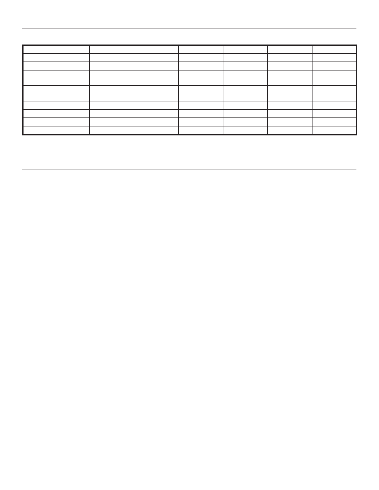
The range of loop amplifier models have a variety of options to suit a wide variety of installation requirements.
DL107 NET DL107 NET D DL207 NET DL207 NET D DL210 NET 2.0 DL210 NET D 2.0
Input: Mic/Line 1 1 1 1 2 2
Input: Line 1 1 1 1 2 2
6
Page 7
DL107, DL207 and DL210 2.0 Digi-Loop™ DSP Induction Loop Amplifiers
DL107 NET DL107 NET D DL207 NET DL207 NET D DL210 NET 2.0 DL210 NET D 2.0
Input: 70-100 Volt 1 1 1 1 1 1
Input: Dante™ 1 1 1
Output: Loop
Loop Output Power: 9.5 Arms/13.4 Apk
Output: Line 1 1 1 1 2 2
Output: Headphone 1 1 1 1 1 1
Output: Speaker 1 (swap loop A) 1 (swap loop A)
Network Control x x x x x x
1 1
16.1 Vrms/22.8 Vpk
9.5 Arms/13.4 Apk
16.1 Vrms/22.8 Vpk
2
(dual or phased array)2(dual or phased array)2(dual or phased array)2(dual or phased array)
9.5 Arms/13.4 Apk
16.1 Vrms/22.8 Vpk
9.5 Arms/13.4 Apk
16.1 Vrms/22.8 Vpk
12 Arms/17 Apk
33.3 Vrms/47.6 Vpk
All of these models conform to IEC 62489-1 Benchmark Testing Specifications.
Main Features (these vary by model)
• Active protection against short and open circuits (all models) • Meets ADA/ADAAG Guidelines (all models)
• Power-save mode (all models) • Remote Monitoring Support (all models)
• Fan-cooled, temperature regulated (all models) • 2 year Warranty (all models)
• High output current:
9.5 A x1: DL107
9.5 A x2: DL207
12.0 A x2: DL210 2.0
• Speaker output (DL210 2.0 only)
• Input configurable as microphone input or line input,
balanced or unbalanced:
XLR: DL210 2.0
3-position terminal block: DL107/207
Ideal applications for loop systems
• Courtrooms
• House of Worship
• Hearing Assistance
• Conference Rooms
• Master gain Control (all models)
• Active protection against shorted or open loops (all models)
• Loop-through Line Output (all models)
• Pink Noise (all models)
• Priority Input (all models)
• Standard 19” rack mount:
1RU: DL107, DL207
2 RU: DL210 2.0
12 Arms/17 Apk
33.3 Vrms/47.6 Vpk
7
Page 8
DL107, DL207 and DL210 2.0 Digi-Loop™ DSP Induction Loop Amplifiers
Getting started: Connecting the amplier
Connection Diagram
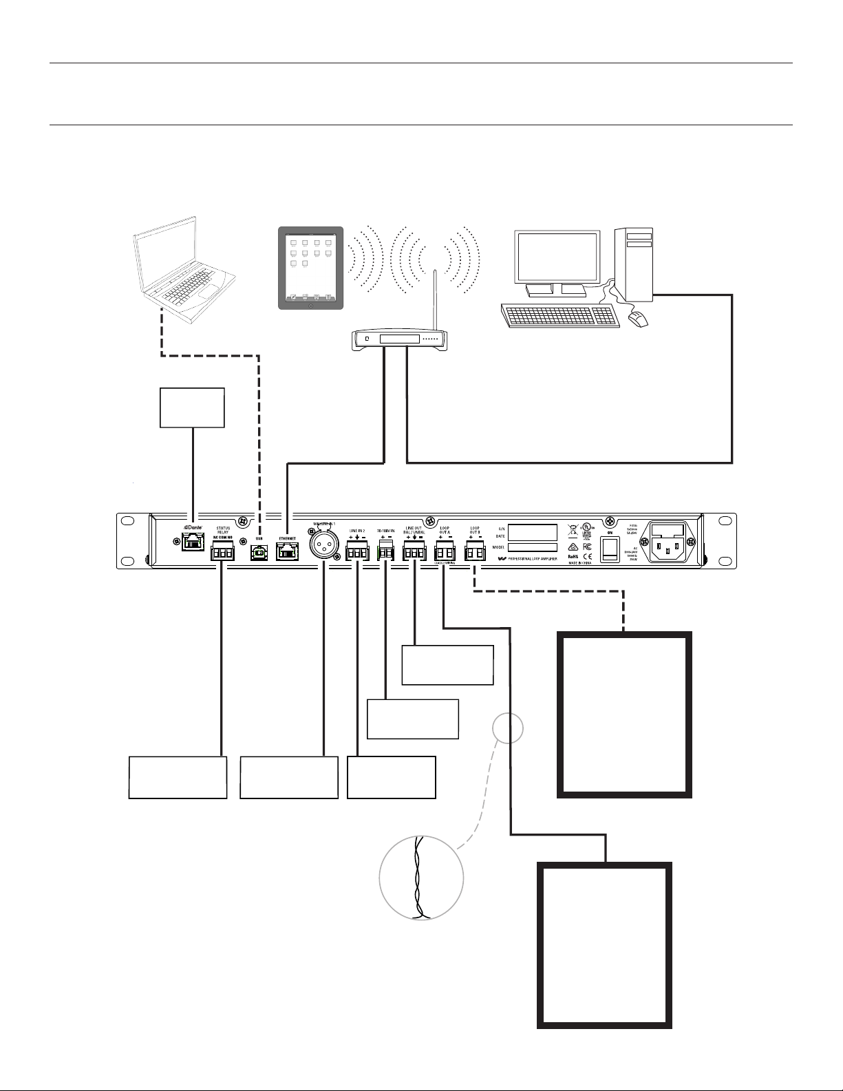
The following diagram provides an overview of typical connections. Connect the amplifier as required for your installation.
The amplifier must be connected to the load (loop wire) prior to powering it on. If it is not, it will present a fault message and shut down.
NETWORK
DANTE
AVAILABLE ON
NET-D
MODELS ONLY
DANTE
iPAD OR WINDOWS
TABLET WITH WI-FI
USB
FIRMWARE
UPDATES
or
DIRECT
CONTROL
with PC
ETHERNET
ONLY FOR
CONTROL.
FIRMWARE
CANNOT BE
UPDATED
THROUGH
ETHERNET.
ROUTER
TO RECORDING
EQUIPMENT
FROM COMMERCIAL
SPEAKER SYSTEM
FIRMWARE UPDATES CANNOT BE DONE THROUGH ETHERNET
FOR IPAD/PC APP CONTROL ONLY
ETHERNET
INDUCTION LOOP
#2
(2nd loop output
available on
DL207/210
models only)
EXTERNAL CONTROL
SYSTEM, ETC.
AUDIO FROM MIXER,
MICROPHONE, ETC.
LINE-LEVEL AUDIO
FROM MP3 PLAYER,
MIXER, ETC.
NOTE: LEAD WIRES
(FROM AMP TO LOOP)
SHOULD ALWAYS BE
TWISTED
TO MINIMIZE EMI
INDUCTION LOOP
#1
8
Page 9
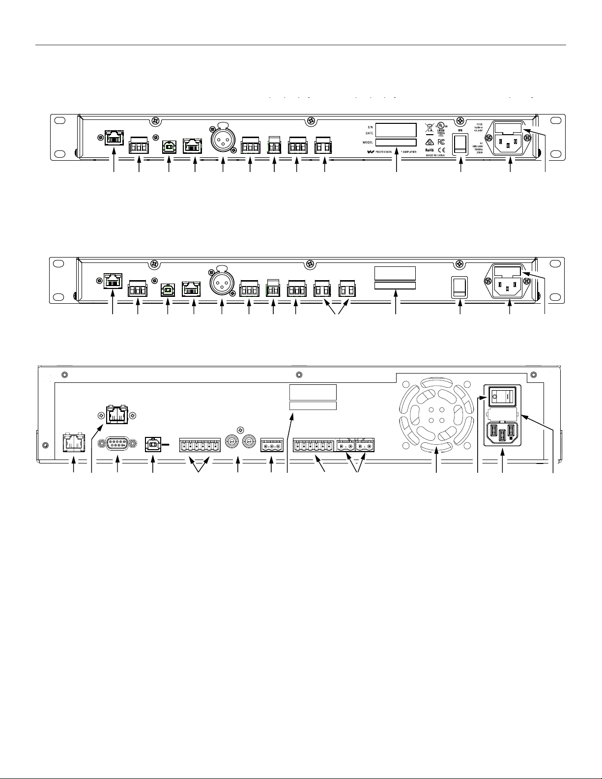
Rear connectors
Front LCD Menu (GUI) display Headphone jack
Menu (GUI) display control knob
DL107/207
Front LCD Menu (GUI) display Headphone jack
USB
jack
Dante jack
(“D” models only)
Ethernet
jack
Mic/Line
level
inputs
Line
level
output
Spkr
level
input
Loop
output
Power
switch
Line cord
connection
Fuse
access
Loop fault
relay
Line
level
input
Model &
Serial
numbers
Menu (GUI) display control knob
DL107/207
DL107
Front LCD - Menu (GUI) Display
Menu (GUI) display control knob Headphone jack
Rear Panel (DL107 NET D shown)
DL107
DL107, DL207 and DL210 2.0 Digi-Loop™ DSP Induction Loop Amplifiers
Dante jack
(“D” models only)
Loop fault
relay
USB
jack
Rear Panel (DL207 NET D shown)
DL 207
Dante jack
(“D” models only)
Loop fault
relay
Rear Panel (DL210 NET D 2.0 shown)
USB
jack
Ethernet
jack
Ethernet
jack
Mic/Line
level
inputs
Mic/Line
level
inputs
Line
level
input
Line
level
input
Spkr
level
input
Spkr
level
input
Line
level
output
Line
level
output
Loop
output
outputs
Loop
Model &
Serial
numbers
Model &
Serial
numbers
Power
switch
Power
switch
Line cord
connection
Line cord
connection
Fuse
access
Fuse
access
Ethernet
jack
Dante
jack
(”D”
model
only)
RS-232 &
Fault Relay
jack
USB
jack
Mic/Line
level
inputs
Line
level
inputs
Speaker
level
input
Model &
Serial
numbers
Line
level
outputs
Loop
outputs
Exhaust
Fan
Power
Switch
Line cord
connection
Fuse
access
9
Page 10
DL107, DL207 and DL210 2.0 Digi-Loop™ DSP Induction Loop Amplifiers
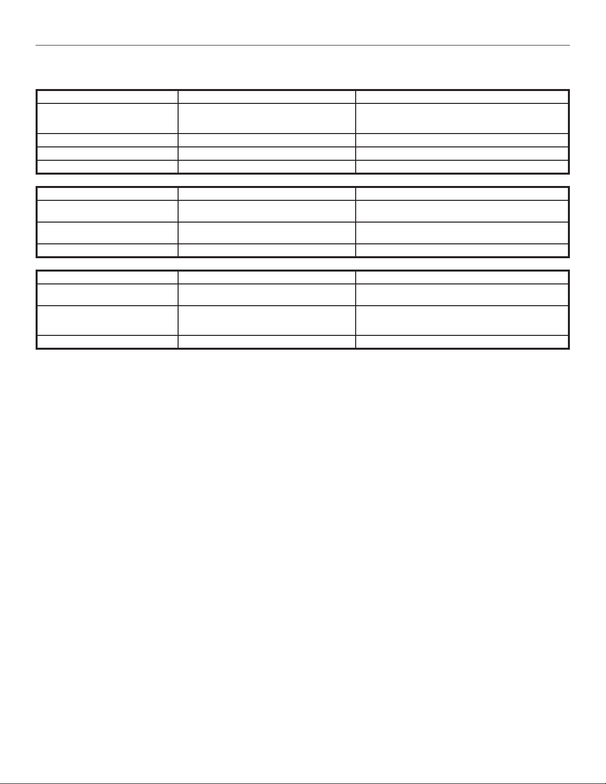
The following table provides a quick reference to each connector’s use and configuration adjustments.
Input Connector Conguration/Control
Mic/Line
(balanced or unbalanced)
Unbalanced Line RCA -10 dBV
70-100 Volt terminal block -
Dante™ RJ-45 -
Control Connector Purpose
Ethernet RJ-45
USB USB-B
RS-232 DB-9 loop fault relay output
Output Connector Specications
Line level
Loop
Speaker terminal block output A (configurable) 125 W @ 8Ω
terminal block
(versions 1.1, 2.0 or 3.0 supported)
terminal block
terminal block
Mic Gain: +9 dB to +63 dB (48v phantom power)
Line levels: -10 dBU, -4 dBU, +4 dBU, +8 dBU
48v Phantom Power
Control and monitoring over the network
using PC App or MLM
Firmware Updates,
Control by PC App
mirrors the audio of the loop outputs
+4 dBU, balanced or unbalanced
12 Arms/17 Apk,
33Vrms/47.1 Vpk,
0.5 to 3.0 Ω dc
Rack Installation
1. Install into a 19” rack using standard 10-32 rack screws.
2. Leave 1U rack space above for ventilation.
3. A surge protector or power conditioner is highly recommended.
4. Use a grounded outlet.
5. Connect all input/outputs before applying power.
6. Plug in the power cord and turn on the unit.
USB Cable Wiring
A standard USB cable (USB Male A to Male B) can be used to connect a computer (such as a laptop) to the Loop Amplifier directly for initial configuration.
No drivers are necessary, simply plug-in a USB cable, open the PC App, specify USB connection, and the PC App can be used to change settings on
the amplifier. Note: Firmware upgrades can only be done through the USB connection. They cannot be performed through Ethernet.
Ethernet Wiring
If connecting directly from a Computer to the Loop Amplifier, an Ethernet Crossover Cable must be used.
If connecting through a network, a standard ethernet cable must be used to connect the Amplifier to the network, and a standard ethernet cable
must be used to connect the Computer to the network.
If a third party controller will be used, a standard ethernet cable can be used to connect the amplifier and controller to the network.
Note: A standard ethernet cable is terminated with either T568A pinout on both ends, or T568B pinout on both ends. A crossover cable has T568A
pinout on one end, and T568B pinout on the other end. See the internet for more information about terminating ethernet cables.
10
Page 11
DL107, DL207 and DL210 2.0 Digi-Loop™ DSP Induction Loop Amplifiers
(not supported)
ON
100 MBps link detected
(supported)
ON
Green Amber
BLINKING
Network Activity
Green Amber
Dante Jack Network LED indicators
Using the Dante Audio Input
The DL107/207/210 NET D models provide a Dante RJ-45 network jack. The addition of the Dante jack enables a virtually unlimited number of
digital audio sources to be routed and streamed to the amplifier.
To change the parameters of Dante (i.e. IP address, Dante Device Name) you must use the Dante Controller software on a PC. The Dante
parameters can be viewed, but cannot be set, on the front LCD Display on the loop amplifier (or PC App). For more information on configuration
and usage of Dante Controller, please visit Audinate’s website at: https://www.audinate.com/products/software/dante-controller.
Note: Dig In L and Dig In R are separate channels of audio. They can be used, for example, if two dierent audio programs are desired, Dig In L
could be routed to one loop and Dig In R routed to the other loop. The mixer functions are used to route each channel to the desired loop. See “5.
INPUT CONFIGURATION” on page 31 for more information about configuring these inputs.
Format
• Sample Rate: 44.1 & 48 kHz
• Bit Depth: 24 bits
Dante network
Connect via Ethernet
Set the Dante ethernet settings in the server to
• Obtain an IP address automatically
• Obtain DNS server address automatically
Dante Controller
All Dante device setup and source routing is performed through Dante Controller. This includes the IP Address and Dante Device Name that
appear in the loop amplifier Net Info screen. If a name change is desired, or the Dante IP Address needs to be set, refer to Dante Controller
documentation. To view the amplifier settings configured by Dante Controller, go to System Conguration - Tech Tools - Net Info and scroll down
to the Dante section.
The Dante jack LED indicators operate dierently than standard ethernet jack LEDs. See illustration below.
Dante jack LED indication (this diers from standard ethernet).
OFF
Green Amber
No Network Link
OFF
ON
Green Amber
10 MBps link detected
OFF
ON
Green Amber
100 MBps link detected
(supported)
ON
BLINKING
Green Amber
Network Activity
11
Page 12
DL107, DL207 and DL210 2.0 Digi-Loop™ DSP Induction Loop Amplifiers
No
DL 107/207 (207 shown)
DL210
Ye s
Mic/Line Input
(XLR balanced)
Line Input
(Phoenix Block)
Analog Audio Input Connections
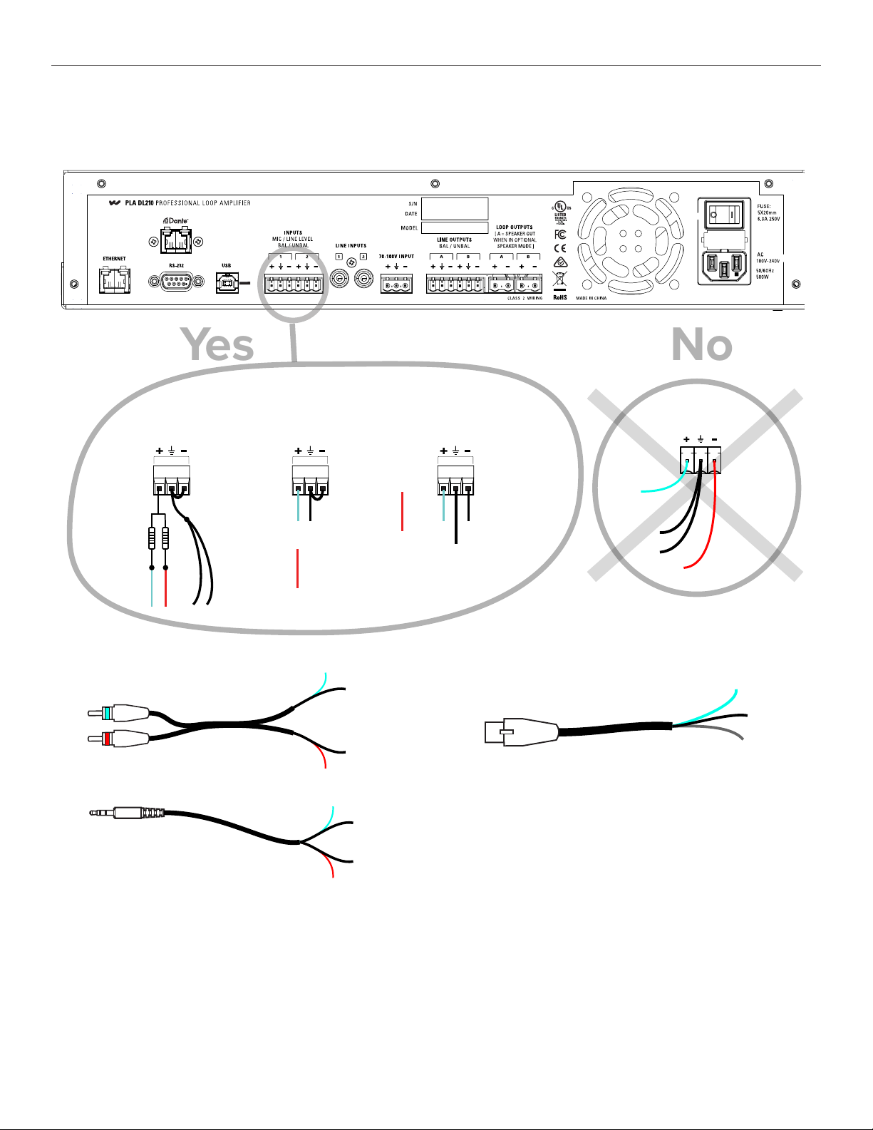
The DL107/207 amplifiers have an XLR Mic/Line input for accepting the balanced output of a microphone or mixer. These models also have a
phoenix-block line input. The DL210 only has phoenix-block line level inputs. The following is how the phoenix blocks would be wired.
Unbalanced stereo
summed
on mono channel
1kΩ,1/8 W
Resistors
L+ R+
Unbalanced Sources
RCA
3.5mm
shields
(gnd)
Unbalanced mono on
mono channel
L+
shield
(gnd)
Not
R+
Used
L+
white
red
white
shield (gnd)
shield (gnd)
R+
L+
shield (gnd)
Balanced mono on
mono channel
R+
L+ L-
Not
Used
common
(gnd)
Balanced Sources
XLR
mono left
L+
shields
(gnd)
LR-
R+
L+
common
(gnd)
L-
Loop Fault Relay Overview
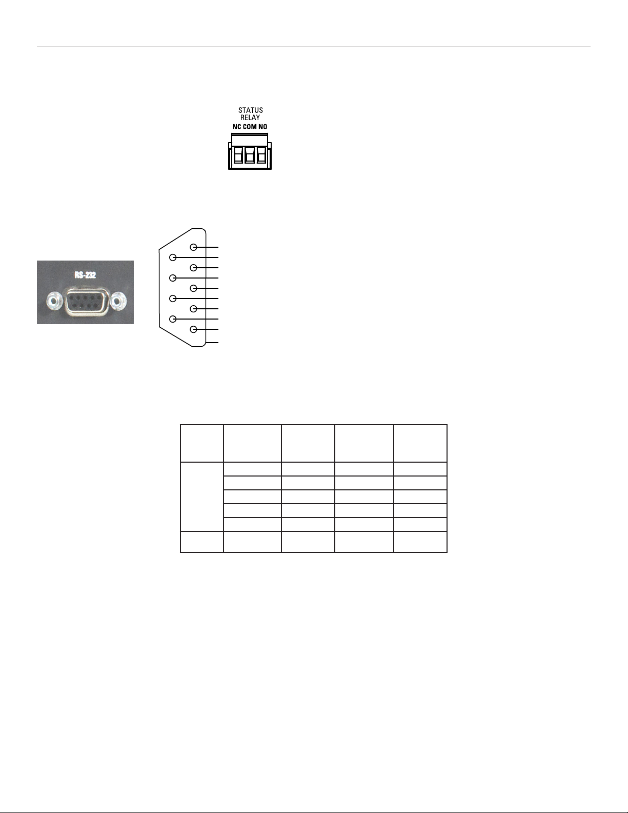
The loop fault relay provides a NO (normally open) and NC (normally closed) contact closure for triggering an external device or control
system when a fault (shorted or open loop) occurs. The external control system can then send a text or email, initiate an alarm, or turn on a
light to let personnel know that a loop fault has occurred.
red
12
shield (gnd)
R+
Page 13
DL107, DL207 and DL210 2.0 Digi-Loop™ DSP Induction Loop Amplifiers
232 REQUEST TO SEND (NOT USED)
DL107/207 Loop Fault Relay Connections
The DL107/207 models provide a loop fault relay through a 3-position terminal block connection on the rear of the amplifier.
Pin 1 - NC (Normally Closed)
Pin 2 - Relay GND
Pin 3 - NO (Normally Open)
DL210 2.0 Loop Fault Relay connections
The DL210 models provide the relay as part of the RS-232 DB-9 connector. The relay and RS-232 use separate pins and are completely isolated.
1
6
2
7
3
8
4
9
5
LOOP FAULT NO
LOOP FAULT NC
232 RECEIVE DATA
TRANSMIT DATA
232 CLEAR TO SEND (NOT USED)
LOOP FAULT GND
232 RING INDICATOR (NOT USED)
232 SIGNAL GROUND
CHASSIS GROUND (NOT USED)
RS-232:
Pin 2 - Receive
Pin 3 - Transmit
Pin 5 - Signal GND
Loop Fault:
Pin 1 - Loop Fault NO
Pin 4 - Ground
Pin 6 - Loop Fault NC
Loop Wire Selection
To select the proper wire for the loop(s), refer to the following chart. Wire resistance of each loop needs to be 0.5 - 3.0 Ω as required by the
amplifier.
Wire type AWG / (CSA)
18 (0.82 mm2) 6.4 234 (71 m) 78 (24 m)
16 (1.3 mm2) 4.2 360 (110 m) 120 (37 m)
Single
conductor
Flat 3/4”
copper
14 (1.9 mm2) 2.4 630 (192 m) 210 (64 m)
12 (3.3 mm2) 1.5 1000 (305 m) 333 (101 m)
10 (5.3 mm2) 1.0 1500 (457 m) 500 (152 m)
~14 (1.9 mm2) 2.4 630 (192 m) 210 (64 m)
DCΩ per
1000 ft
(305 m)
Max length
Approx ft (m)
Min length
Approx ft (m)
13
Page 14
DL107, DL207 and DL210 2.0 Digi-Loop™ DSP Induction Loop Amplifiers
Powering Up
Connect the inputs and outputs as desired (referring to the last section). Make sure the loop wire resistance measures 0.5Ω - 3Ω. Connect the IEC
power cable supplied, and power up the amplifier using the switch on the back panel.
Initial Conditions
The amplifier, out of the box, powers up with factory settings according to Table 1 and Table 2.
No input selection is necessary for an output to be heard if the source is connected to any of the inputs.
All inputs are initially routed to the loop outputs at a gain setting of -12 dB.
INITIAL INPUT SETTINGS
Input Name Type Settings
1 & 2 Dig L/Dig R Dante -
3 & 4 Input 1/2 Mic/line, balanced or unbalanced Line level, -10 dBU, phantom power OFF
5 & 6 Line 1/2 Unbalanced line Line level, -10 dBU
7 70-100V 70/100 volt Level: 25 Vrms
INITIAL OUTPUT SETTINGS
Output Name Mode Settings
1 Loop A DL107: Single Loop
DL207/DL210: Dual Loop
2 Loop B DL107: Single Loop
DL207/DL210: Dual Loop
3 Line A mirrors the audio of the loop outputs
all inputs are routed to this loop at -12 dB
all inputs are routed to this loop at -12 dB
4 Line B mirrors the audio of the loop outputs
Loop Termination Warnings
After powering up, the unit will test the loop resistance. If the loop has not been termianted, or has an open circuit, a warning will pop up that the
Amplifier has shut down. Push the “Adjust” button in to dismiss the warning. The Home Page loop status appears indicating FAULT. Periodically the
previous warning pop up will reappear, requiring the operator to press enter again.
If this happens the loop wire resistance must be fixed. If the outputs are now terminated with the proper resistance, the amplifier will not
automatically reset to operational status. The amplifier must be rebooted.
If a loop is disconnected from the amplifier, a warning will not come up. If the amplifier is rebooted, the warning will now appear.
To avoid warnings due to an open circuit, terminate the unused loop outputs with a resistor such as a 1Ω, 100 Watt resistor or similar.
Note: the amplifier runs a loop test each time it is powered up. So to recover from a fault condition the amplifier must be turned OFF then ON again.
14
Page 15
DL107, DL207 and DL210 2.0 Digi-Loop™ DSP Induction Loop Amplifiers
Checking and updating rmware
To check the rmware version on the amplier:
By the time the amplifier is to be installed, the firmware may be out of date. The amplifier will not always arrive with the latest firmware version
either. For best performance it is highly recommended to check & upgrade the firmware.
There are two ways to view the current firmware version on the unit:
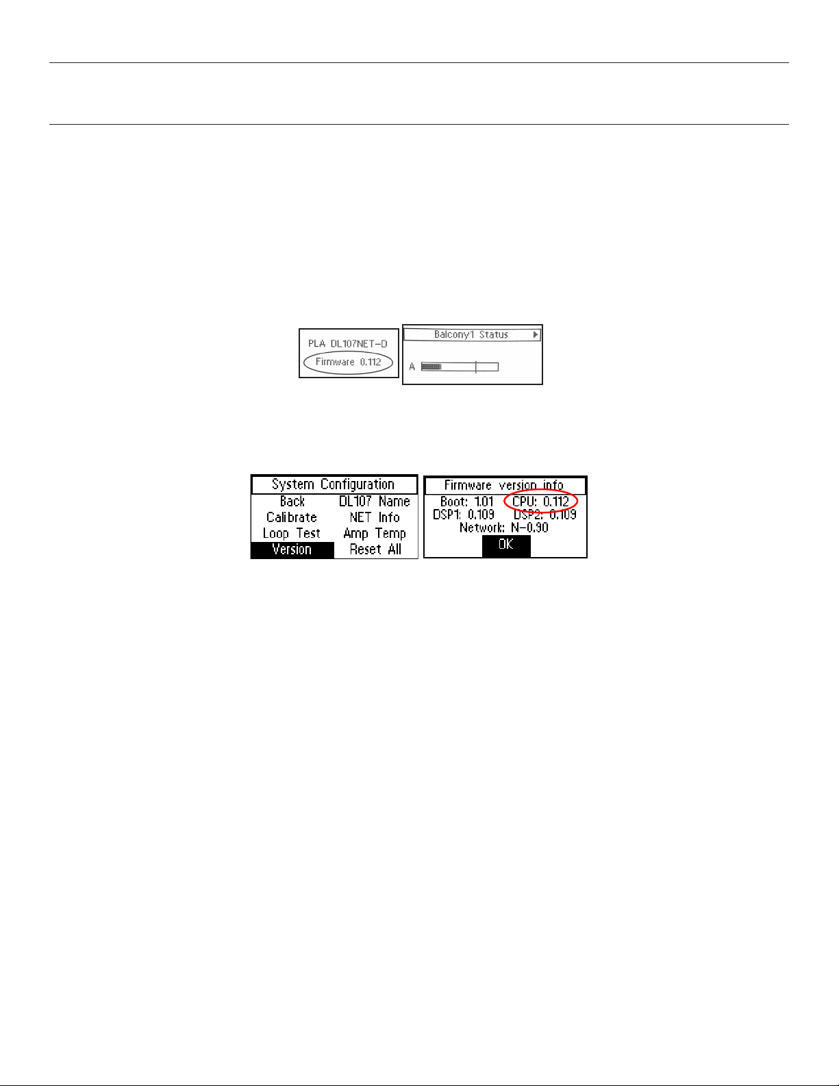
1. Front LCD - During boot-up
Power ON the amplifier and watch the LCD screen. The firmware version is displayed after the Williams AV logo is displayed, and before
the loop status check and output VU meters are displayed.
2. Front LCD - Version Info Screen
If the amplifier is already powered ON, it is easy to view the firmware version without shutting the amp OFF.
Using the LCD Menu control knob, navigate to System Configuration - Tech Tools - Version. The current version is displayed by CPU.
To update the rmware on the amplier:
If a newer version of firmware exists on our website, use the steps listed on the firmware download page to upgrade the firmware in the amplifier.
There are two version of firmware - one for the 210 models and another for the 107/207 models. Take care to download the correct version!
15
Page 16
DL107, DL207 and DL210 2.0 Digi-Loop™ DSP Induction Loop Amplifiers
Installing and conguring the PC App
The PC App is used to configure and commission the amplifier.
When configuring the amplifier, the ethernet connection is recommended for best performance (crossover cable required).
The ethernet connection cannot be used for firmware updates. The USB port must be used for rmware updates.
The USB port can be used with the PC App, but performance may be limited.
Hardware Requirements:
Desktop/Laptop Computer Windows PC. Mac PC not supported.
Mobile Device Windows Surface Tablet
Operating System Compatibility Windows XP
Ethernet 10/100 GB
USB 1.1
Windows Vista
Windows 7
Windows 8
Windows 10
Microsoft .NET 4.0.30319 minimum.
Standard RJ-45 jack.
2.0 (12 MBs high speed)
3.0 (5 GBs super speed); standard “B” jack.
To install the PC App:
Download the PC App by visiting our website www.williamsav.com.
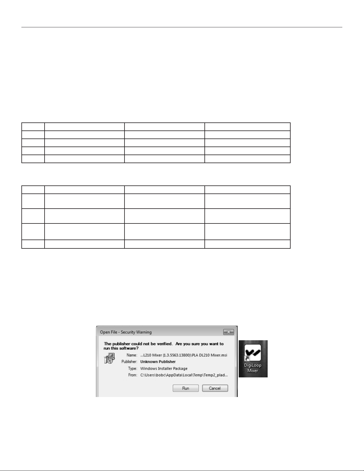
Follow the instructions to install the PC App. When the installation completes it will create this icon in the programs/apps directory:
16
Page 17
DL107, DL207 and DL210 2.0 Digi-Loop™ DSP Induction Loop Amplifiers
Ethernet Control Setup
A crossover ethernet cable must be used when directly connecting a PC to the amplifier.
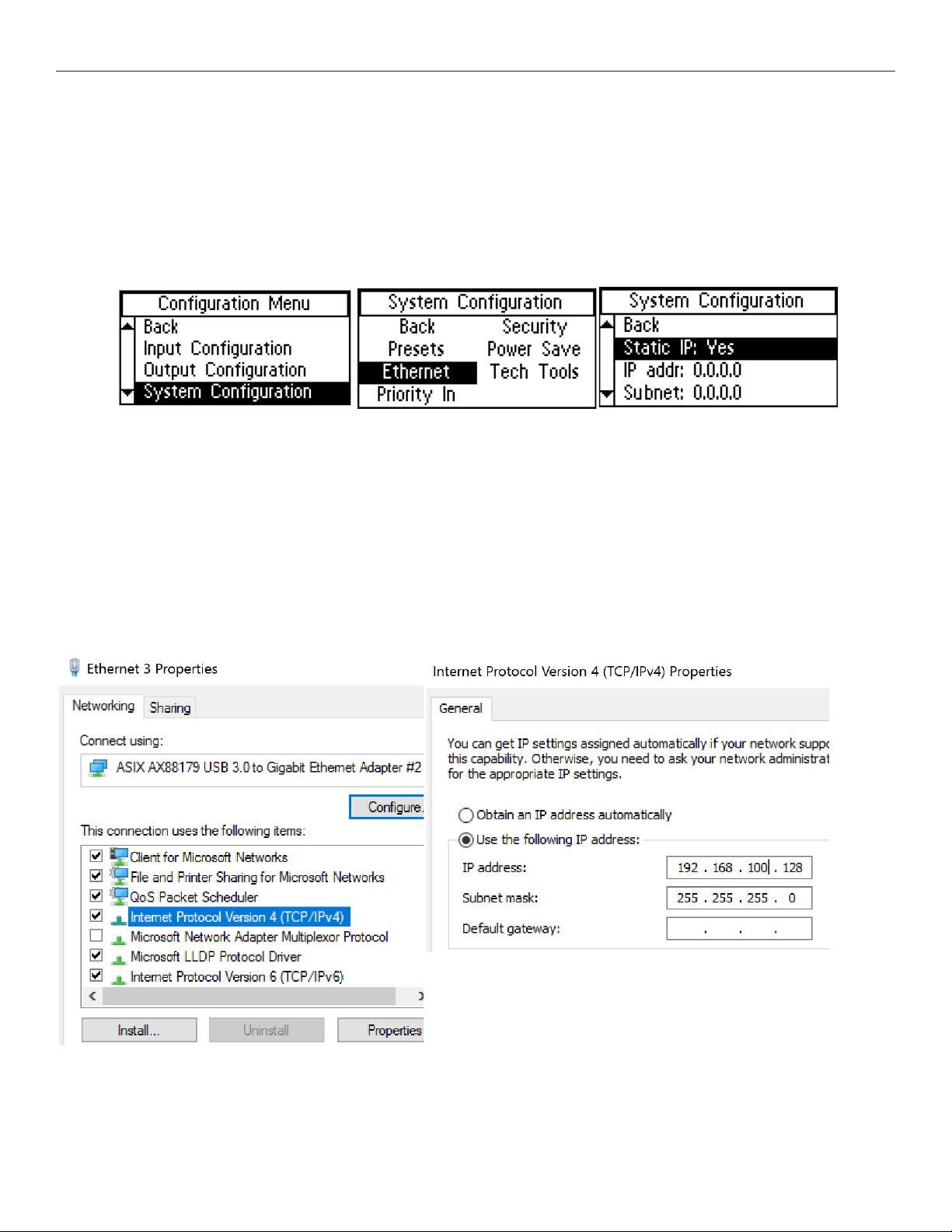
Before the PC App can be used, an IP Address must be assigned to the amplifier using the front LCD menu. The PC must have it’s own unique IP
address on the same subnet. Then the IP Address of the amplifier needs to be entered into the PC App.
Set an IP Address in the amplier.
Using the front LCD menu on the amplifier, navigate to System Configuration - Ethernet.
Fill in the settings below.
• Static IP: Yes
• IP Address: e.g., 192.168.100.127 (this address is only an example)
• Subnet: 255.255.255.0
• Telnet Port: 23
Set the networking properties on the computer to an unused static IP Address.
The static IP should be in the same subnet used in step 1. For this example, set the IP Address to 192.168.100.128. In Windows 10 this is configured
under Network & Internet Settings - Ethernet - Change Adapter Options - (choose ethernet card) - (TCP/IPv4) Properties.
17
Page 18
DL107, DL207 and DL210 2.0 Digi-Loop™ DSP Induction Loop Amplifiers
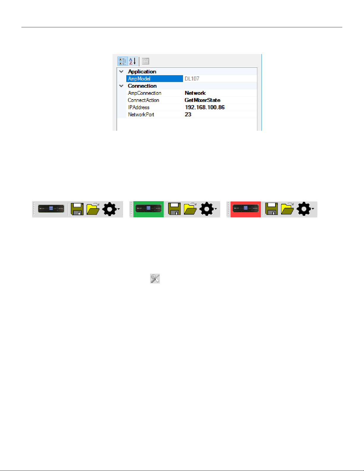
Set the amplier IP Address in the PC App.
1. Select AmpModel from the dropdown list (e.g., DL107, DL207, DL210 or DL210_20).
2. Set the AmpConnection to Ethernet.
3. Set ConnectAction to GetMixerState.
4. Set IP Address to the amplifier’s IP Address.
Click the amplier Connect icon on the top left of the PC App Toolbar.
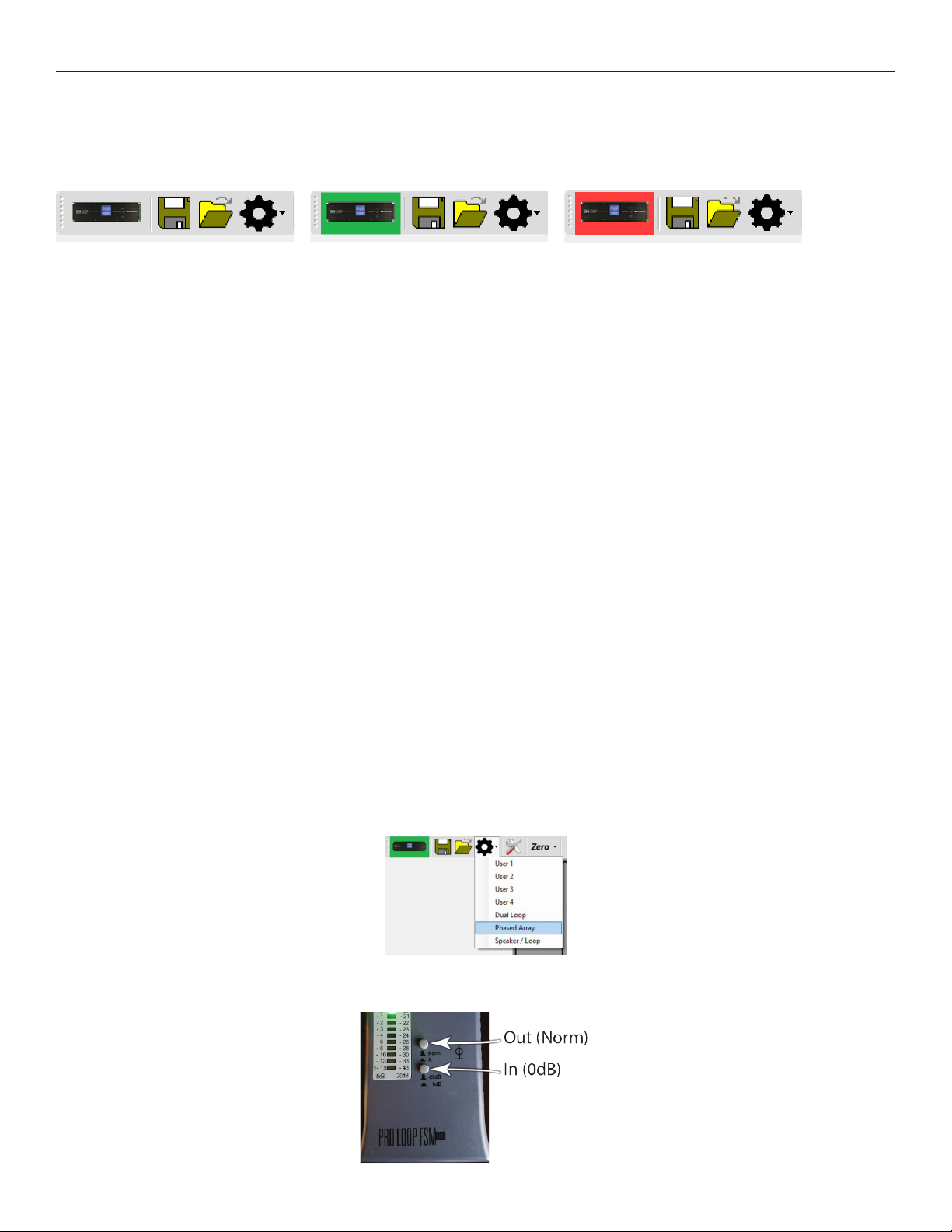
When the computer connects to the amplifier, the symbol will turn Green. If it cannot connect, it will turn Red. The sliders should move and the
VU Meters should pulse, indicating that the computer has pulled the current state information from the amplifier.
Amp symbol before connection attempt: Turns GREEN when connected: Turns RED if cannot connect:
If the symbol turned GREEN, you can now use the PC App.
Note: Under Ethernet control, the amplifier does not update the input levels adjusted by the App, until another function is carried out, such as
pressing the Enter button or moving to another menu.
USB Control Setup
1. Connect the computer to the amplifier with a standard USB cable.
2. Open the PC Mixer App on the computer.
3. Under the settings tab icon on the top toolbar , set AmpConnection to USB and ConnectAction to GetMixerState.
4. Power ON the amplifier.
5. Click the amplifier Connect icon on the top left of the PC App Toolbar.
18
Page 19
DL107, DL207 and DL210 2.0 Digi-Loop™ DSP Induction Loop Amplifiers
When the computer connects to the amplifier, the symbol will turn Green. If it cannot connect, it will turn Red. The sliders should move and the VU
Meters should pulse, indicating that the computer has pulled the current state information from the amplifier.
Amp symbol before connection attempt: Turns GREEN when connected: Turns RED if cannot connect:
If the symbol turned GREEN, the PC App is ready to use.
Note: If both channels aren’t terminated with at least 0.5 ohms, the amplifier icon in the PC App may not turn green when trying to connect. If this
happens you will need to fix the problem, disconnect the USB cord between the amplifier and computer, reboot the amplifier, reconnect the USB
Cord and try to connect again.
If the PC App has detected a fault, such as Loop B not being terminated with at lest 0.5 ohms, even when the amp is terminated and rebooted the
PC App will still indicate Loop B: Error even though the amplifier does not indicate this fault. If this happens, perform a loop test from the toolbar to
clear this condition. If the PC App still indicates Loop B: Error the PC App will need to be closed and re-opened to pull the new state information
from the amplifier.
Calibrating & commissioning the loop amplier
The loop amplifier must be calibrated to the field strength of the loop or the VU Meters and settings adjustments will not be accurate.
An external source (such as a test tone generator) CANNOT BE USED to calibrate the amplifier. The internal test tone generator MUST be used.
Calibration and commissioning are necessary to meet IEC Spec 60118-4.
Equipment required: Field Strength Meter, USB cable (or crossover ethernet cable), and a Windows-based PC.
Requirements:
• a Background Noise Check was performed with a field strength meter
• a Test Loop was verified with the amplifier connected
• the permanent loop wire(s) measure 0.5-3.0 ohms (including lead wires)
• the latest firmware is loaded in the amplifer
• the latest PC App is installed on the PC
1. Start communication between the PC App and Amplier.
Refer to “USB Control Setup” on page 18 for this example.
2. Load preset factory defaults for Loop type.
This clears previous settings and loads preconfigured factory settings for the loop type. The loop type is either a Single Loop, Dual Loop or
Phased Array. The DL210 models oer a Speaker + Loop preset and this is used for a single loop. DL107/207 models have a Single Loop
preset.
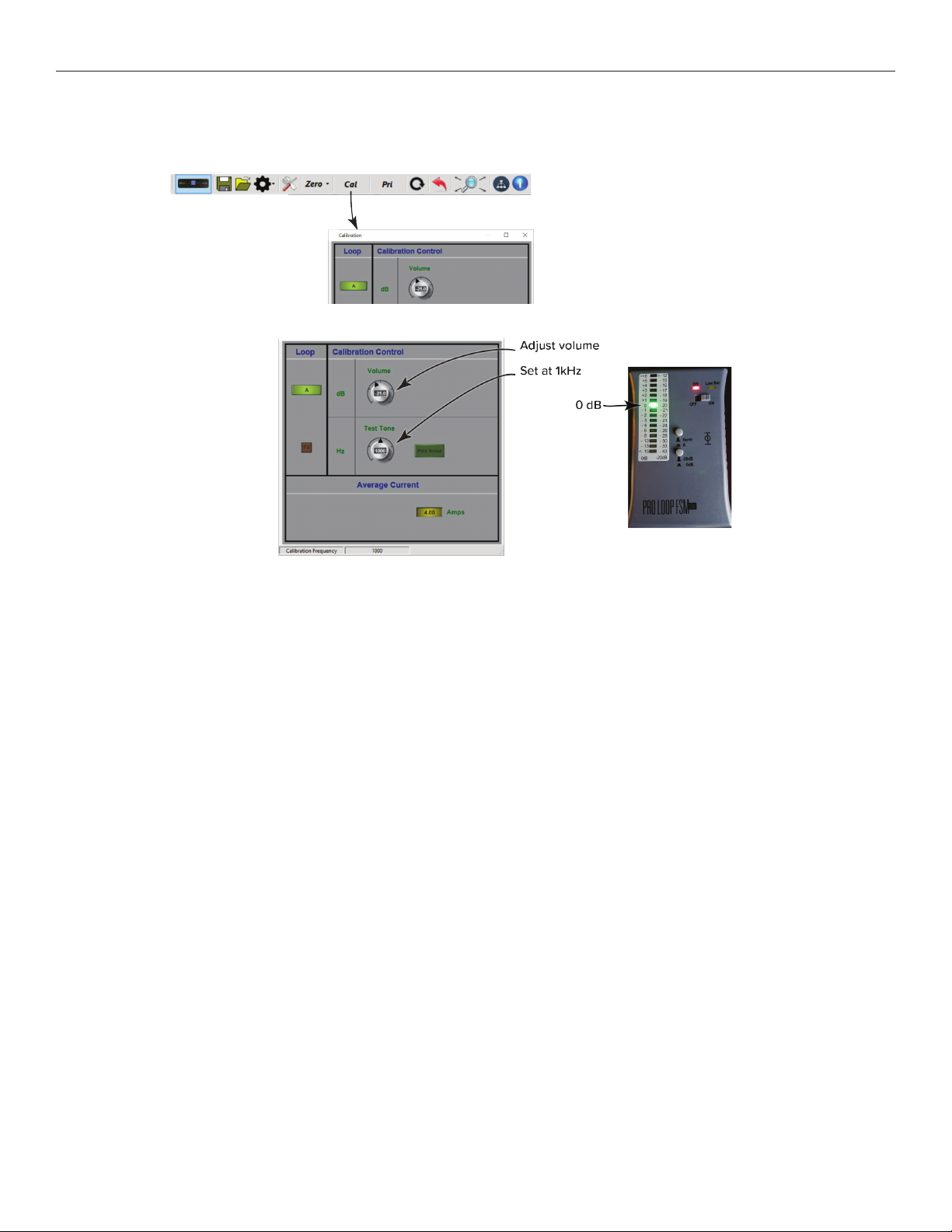
3. Calibrate the amplier to a eld strength of 400 mA/m at 1 kHz, with FSM 5 ft above oor.
a. Set the FSM switches - top button depressed out: Norm; bottom button pushed in: 0dB.
19
Page 20
DL107, DL207 and DL210 2.0 Digi-Loop™ DSP Induction Loop Amplifiers
b. Set or hold the FSM at 5ft above the floor, in the center of the loop or array.
c. Open the Calibration Window in the PC App.
d. Set the Frequency to 1 kHz, and adjust the volume level until the Field Strength Meter reads 0 dB.
e. For Phased-Array only: Switch to Loop B (by clicking on the A button) and turn up the volume until the current for Loop B is close to Loop A
(within 0.2A).
The loop amplifier is now calibrated. This is the 0 dB calibrated reference point that the EQ adjustments will reference. It also makes the Input
and Output VU Meters accurate.
The volume adjustment in the Calibration Window (test tone) should not be changed after this. Doing this will take the amplifier out of
calibration. The EQ adjustments in the next step have their own level adjustment controls.
If more output is desired from the loop, the Source volume should be adjusted first, then the Input Sliders, then the Output Eects AGC
Control, in that order.
20
Page 21
DL107, DL207 and DL210 2.0 Digi-Loop™ DSP Induction Loop Amplifiers
4. Equalize other frequencies to match the calibration point.
Make sure the switches on the field strength meter are in same position as they were for calibration.
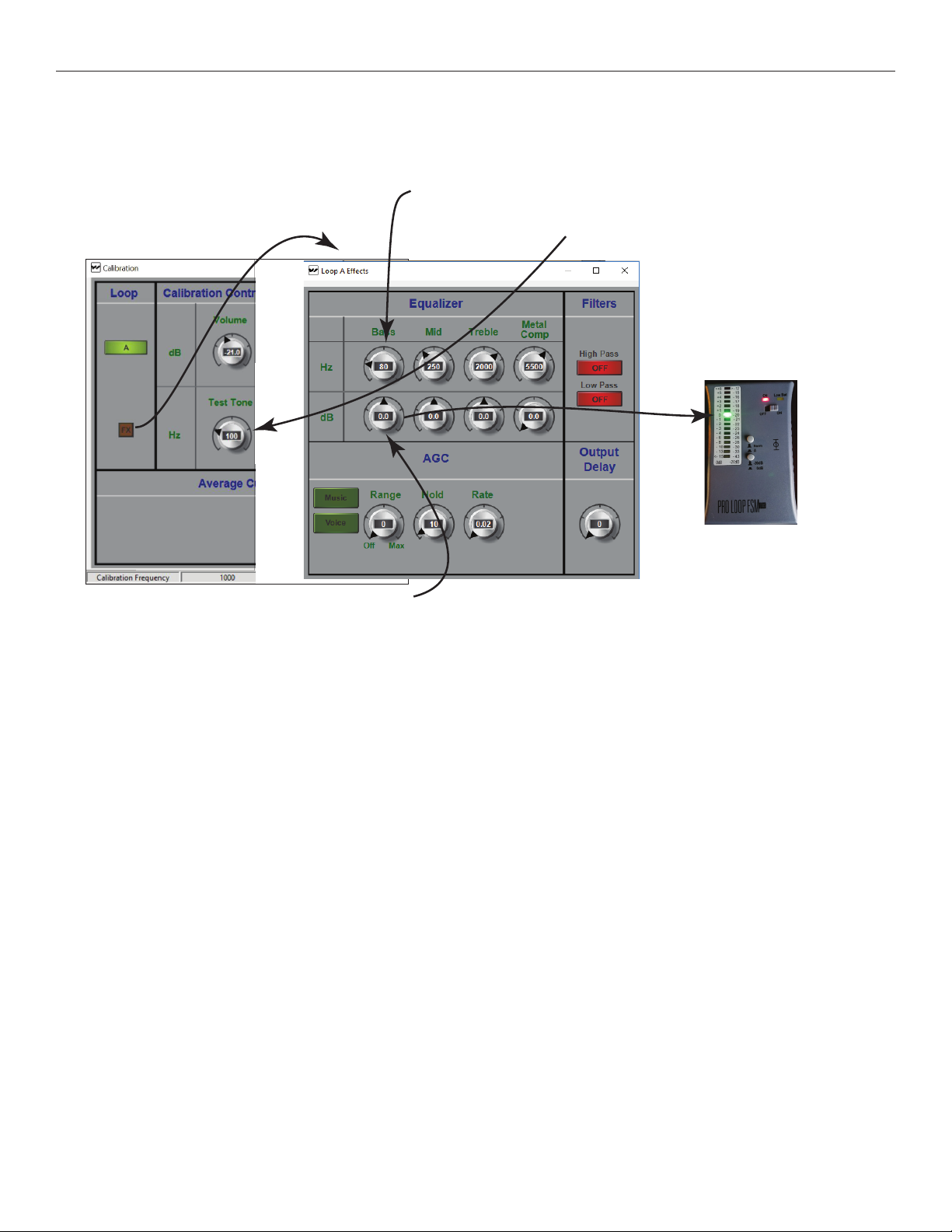
Step a
Open the
Eects Window
Step d
Return to the Eects Window
and adjust theEQ volume (dB) until
the eld strength meter reads 0 dB.
Step b
Bass=100 Hz,
Mid=500 Hz,
Treble=2500 Hz,
Metal Comp=5000 Hz
Step c
Return to the Calibration Window
and set the test tone for 100 Hz
(the rst frequency to be equalized).
Step e
Repeat Steps c & d for the next frequency,
(i.e. 500 Hz). Repeat c & d until each of the
frequencies have been equalized to 0 dB.
a. Open the output EQ settings by clicking on the FX button in the Calibration Window.
b. Set 4 equalizer frequencies, Bass=100 Hz, Mid=500 Hz, Treble=2500Hz, Metal Comp at 5000Hz.
c. Return to the Calibration Window and set the test tone to 100 Hz. The amplifier is now generating 100 Hz in the loop.
d.
Go to the Output Eects Window and adjust the dB level until the field strength meter reads 0 dB. The loop is now equalized for 100 Hz.
e. Repeat steps c & d for the next frequency (i.e. 500 Hz) and continue until each of the frequencies has been adjusted to 0 dB as measured
by the field strength meter.
5. Test with an appropriate audio source (DO NOT USE an external test tone generator).
a. Connect a source such as an MP3 player or smartphone to the Line 1 input.
b. With music playing, observe the Loop Output VU meters on the PC App. They should be peaking around 0 dB.
c. If the output level is not sucient, adjust the Source Volume up.
d. If the output level is still not sucient, adjust the Input Slider up.
e. If the output is not sucient, or if the performance is too dynamic, go into the Output Eects Window and adjust the AGC level up to about 5.
DO NOT go back into the calibration window and adjust the level. This will take the amplifier out of calibration!
21
Page 22
DL107, DL207 and DL210 2.0 Digi-Loop™ DSP Induction Loop Amplifiers
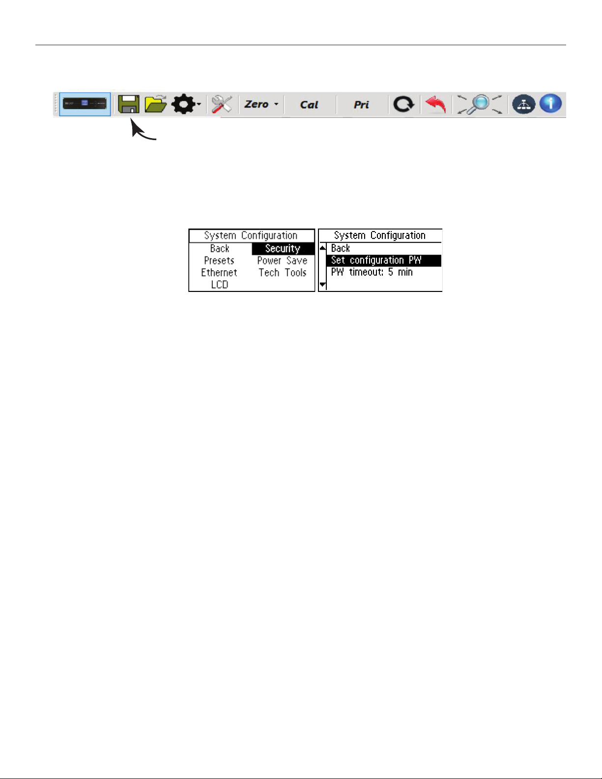
Save configuration settings to a file
6. Save conguration settings to a le
a. Use the Save icon in the PC App
b. Save the file with the project name in the file name.
c. Do not turn o the amplifier for at least 30 seconds after saving settings.
7. Optional - lock amplier with a password.
a. Using the front dial on the amplifier, navigate to System Configuration - Security - Set configuration PW.
b. Record the password somewhere for future reference.
Note: this does not prevent the PC App from working - it protects the unit from being tampered with through the front LCD Menu.
22
Page 23
DL107, DL207 and DL210 2.0 Digi-Loop™ DSP Induction Loop Amplifiers
Appendices
Maintenance & cleaning
The Front Display should be cleaned with a clean, damp microfiber cloth only. This will prolong the life and legibility of the screen. To prevent
scratching, do not use Windex or any other type of cleaner or cloth/paper towel on the screen.
The case can be blown out with compressed air and the outside wiped down with a damp cloth. Windex can be used on the case, as long as it is
not used on the screen.
General Troubleshooting
Problem Solution
• Check to see that the loop amplier is on.
• Make sure the input source is on/playing.
No Sound
Interference / hum /
background noise
Announcements not heard
on 70-100v input
Distorted audio
PC App not controlling the
amplier
• On the Loop Status screen, the horizontal bar graph should be pulsing with the audio from the input source.
• Plug in headphones and make sure the input source is producing audio.
• Check loop connections - are both loop ends connected rmly and are the cable ends properly terminated with exposed wire in the
contacts?
• Are hearing aids/receivers on/set correctly?
• Turn the loop system o and check to see if background noise remains. If it does, the noise may be created by other electrical
systems and picked up by the loop. Turn o nearby appliances to nd the source of the interference.
• If a microphone is connected to the microphone input, try shutting o the microphone or unplugging it. If the noise goes away, turn it
back on and try reducing the microphone input gain.
• Is the announcement source on and working? Can announcements be heard on the 70-100 V speakers?
• Check connections to the amplier. Is the announcement source connected to the 70-100 V input?
• If the announcement source is properly connected, and audio is very low, try increasing the input gain on the loop amplier, or the
output gain of the 70-100 V source.
• With the 70-100 V input selected for the headphone jack, listen with a pair of headphones and verify that the input is receiving audio
• Is the input level set correctly in the amplier? (i.e. Mic/Line level, mic phantom power on/o, etc.)
• Is the source level too high?
• Is the IP address set correctly in the amplier? (System Conguration-Tech Tools-Net Info)
Note: the amplier needs to be rebooted for the IP address to take eect.
• Is the IP address assigned in the amplier the same as the IP Address entered into the PC App?
• Is the correct amplier model selected in the PC App?
• Is the amplier communicating on the network? Can you ping the amplier from a PC on the network?
If not, check the ethernet path (cables, switches, router, etc).
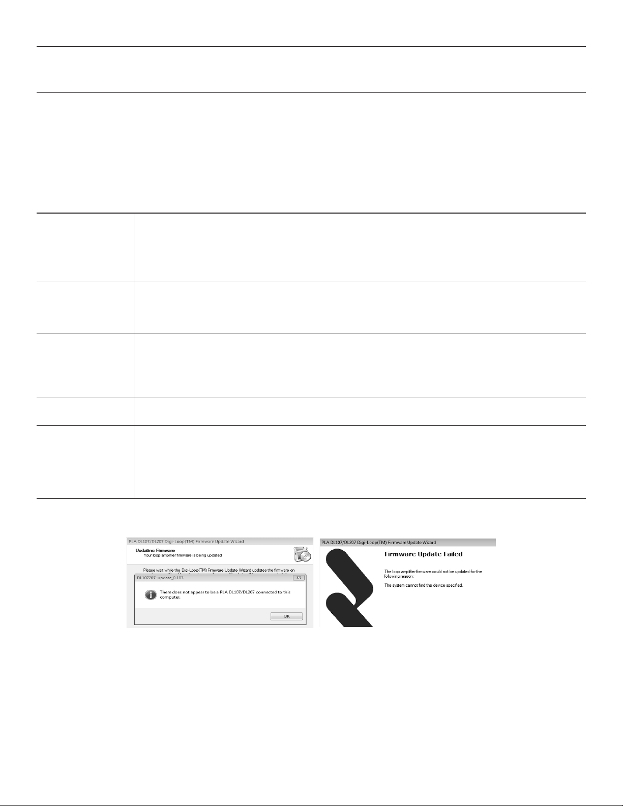
Troubleshooting a rmware update failure
If the installation fails a dialog box will comes up like this:
Generally, firmware updates fail because a connection between the computer and amplifier could not be established. This sometimes happens if
either USB port was previously in use or connected to a device.
23
Page 24
DL107, DL207 and DL210 2.0 Digi-Loop™ DSP Induction Loop Amplifiers
To re-install the firmware, follow these instructions in sequence.
1. Unplug the ethernet and USB cables from the amplifier and computer.
2. Power OFF the amplifier.
3. Power OFF the computer. If the computer is already powered up, shut it down (Do not just reboot). Then power it on. This clears any
previously established telnet connections and makes the USB port ready for connection. Wait for the computer to completely boot into
Windows.
4. Turn on the amplifier and wait for it to fully boot, showing the VU meters on the front LCD display.
5. Connect the USB cable from the computer to the amplifer.
6. Double-click on the firmware exe file to reinstall the firmware.
PC App Detail
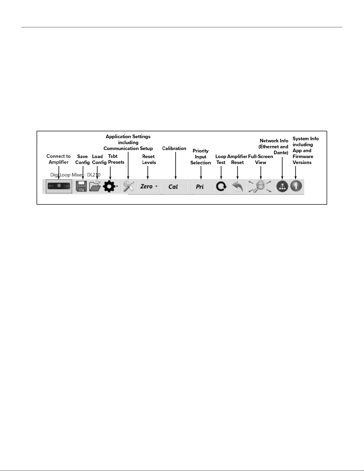
PC APP TOOLBAR
Connect to Amplifier - This symbol establishes connection between the amplifier and the PC. When connected, the indicator turns green.
Save Config - Stores all of the system settings in a file.
We recommend saving the settings in a file in case of power outage or other catastrophic failure. Settings should be saved immediately
after the system is calibrated.
Load Config - Loads saved system settings from a file.
Tsbt Presets - Resets the amplifier to factory default settings or user saved presets.
Application Settings - This is where communication between the amplifier and the PC is set up. You can also change the quality of the graphics or
run a demo of the application - with simulated VU meter activity.
Reset Levels - This will reset all of the slider and rotary dial levels to -INF.
Calibration - This opens the calibration window, which provides a convenient way to calibrate the loop by generating a test tone (using the
amplifier’s internal tone generator), adjusting the frequency and output level, and measuring the signal level of the loop with a field-strength meter.
Note: The field strength meter can be purchased through Williams AV, model PLM FSMP. Please see our website or call us for more information.
Priority Input Selection - Allows selection of an input designated as an override to any/all inputs currently in use. When signal level appears on the
priority input, all other outputs are muted until the signal on the priority input is not present for a period of time. This is useful for overhead paging/
distributed speaker systems where announcements need to be heard by loop users.
Loop Test - Performs a test on the loop(s) looking for an open or faulty loop.
Amplifier Reset - This resets all settings to factory defaults and re-boots the amplifier.
Full-Screen View - This returns the App to a full-screen view if the window has been re-sized or moved.
Network Info - This shows the Ethernet Network Address settings and Dante™ Network Address settings.
System Info - This shows the currently loaded firmware versions of: main CPU, DSP chipsets, network driver and bootloader. It also displays the
current PC App version.
24
Page 25
PC APP MAIN SCREEN
DL107, DL207 and DL210 2.0 Digi-Loop™ DSP Induction Loop Amplifiers
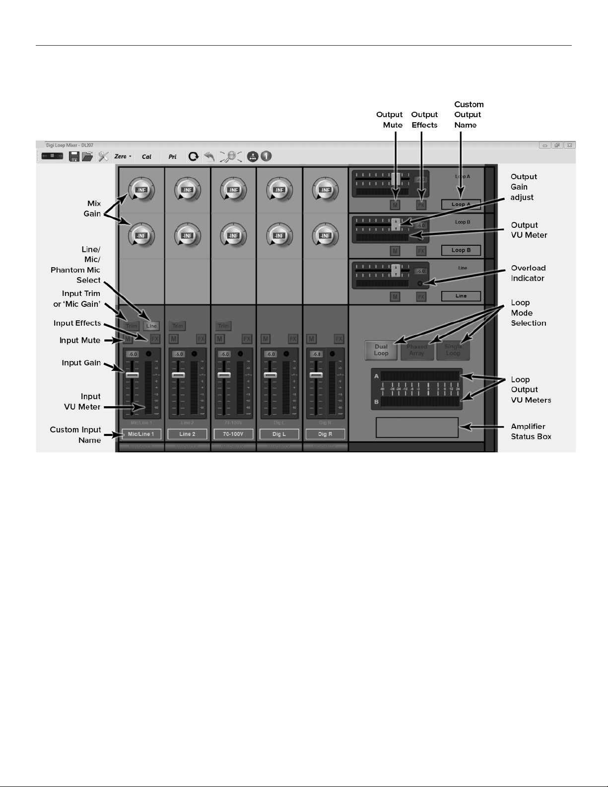
Mix Gain - Allows an additional point of control to mix individual inputs as required for each output. (Click on the dial, then slide up/down to adjust)
Line/Mic/Phantom Mic Select - Switches between a Line-level signal, dynamic microphone or 48 V condenser microphone.
Input Trim - Provides fine trim of the input gain. Caution! It is very important to make sure the appropriate input configuration is set BEFORE plugging the
source into the Input 1 or Input 2 jacks.
Digital In Switch - Switches Digital In L and Digital In R (inputs follow each other) to either Dante or AES/EBU.
Input Eects/Output Eects - Opens the Input or Output Eects adjustment window.
Input/Output Mute - Mutes the Input or Output without the need to use the slider control. Unmute returns to slider gain level.
Input VU Meter/Output VU Meter/Loop Output VU Meters - Shows the active level of the audio post-adjustment.
Input/Output Gain - Gain adjustment slider control.
Custom Input/Output Name - Provides the ability for a custom name. The jack label is preserved above the custom name.
Loop Modes - Changes the internal configuration of the amplifier to drive the load(s) chosen.
Input/Output Overload Indicators - This light will turn red once an overload condition is reached. It remains red until cleared. Clear the overload
indicator by clicking on it.
Status Message Area - If the amplifier encounters error conditions, a specific message will be displayed in this area, i.e. if a loop is open.
25
Page 26
DL107, DL207 and DL210 2.0 Digi-Loop™ DSP Induction Loop Amplifiers
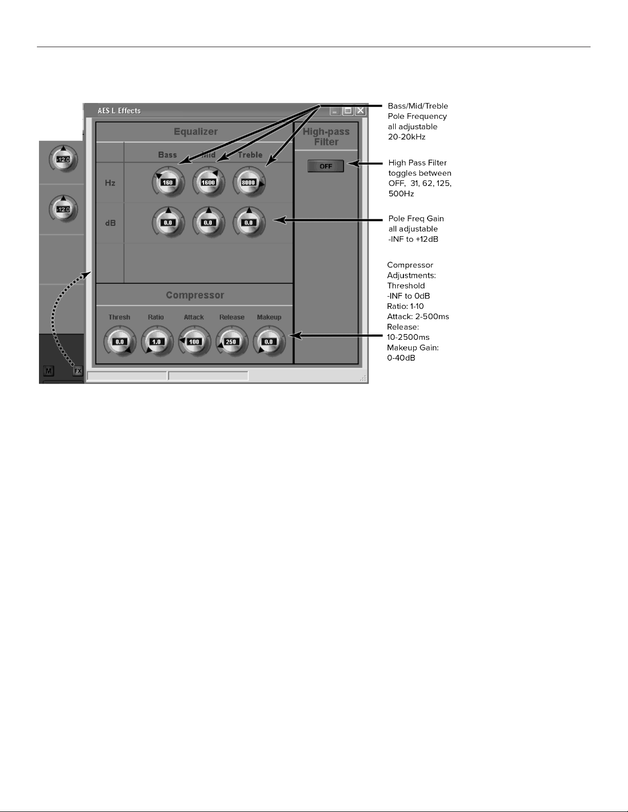
INPUT EFFECTS WINDOW
Equalizer
Hz (Bass/Mid/Treble Pole Freq) - Sets the center frequency for the gain adjustment of each band. (Click then slide up/down to adjust)
dB (Bass/Mid/Treble Pole Freq Gain Adjust)- Adjusts the amount of gain at the pole frequency. This is adjustable from -96.0 dB to 0.0 dB in 0.5 dB
steps.
High Pass Filter
Each push of the button toggles between OFF, 31 Hz, 62 Hz, 125 Hz, 500 Hz, and back to OFF.
Compressor
Threshold is the level of incoming signal at which compression takes eect. The Threshold is adjustable from -96.0 dB to 0.0 dB in 0.5 dB steps.
Ratio determines how much compression is applied when it takes eect. The Ratio is adjustable from 1.0:1 (no compression) to 10.0:1 in 0.1 steps.
Attack is the speed at which compression reacts to get to the target level. The Attack is adjustable from 2 ms to 500 ms in 2 ms steps.
Release controls the time that the compressor continues to work after the input signal drops beneath the threshold. Short settings release the
signal quickly, while long release times have the eect of sustaining the signal. The Release is adjustable from 10 ms to 2500ms in 10ms steps.
Makeup Gain is used to bring the overall level of the sound back up, when the overall volume has been reduced by compression. This happens
when the threshold is set low and/or the ratio has been set high. The Makeup Gain is adjustable from 0 dB to 40 dB in 0.5 db steps.
26
Page 27
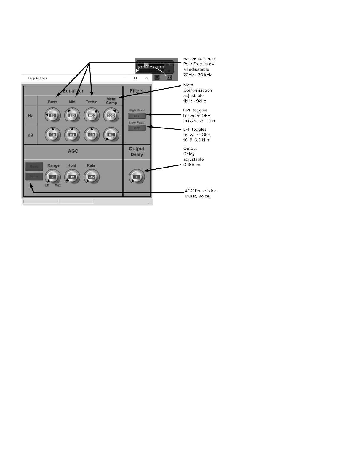
OUTPUT EFFECTS WINDOW
DL107, DL207 and DL210 2.0 Digi-Loop™ DSP Induction Loop Amplifiers
Output eects can be accessed from two dierent places - The FX button in the calibration window, or the FX button near the output slider.
Equalizer
• Hz (Bass/Mid/Treble Pole Freq) - Sets the center frequency for the gain adjustment of each band.
• dB (Pole Freq Gain Adjust) - Adjusts the amount of gain at the pole frequency chosen.
• Metal Compensation - Parametric gain control to overcome high-frequency loss caused by metal absorbing energy from the loop.
AGC (Automatic Gain Control)
Once the amplifier has been calibrated for the loop(s), the AGC (when active) will try to maintain that average level of signal to the loop(s) or speaker.
For people familiar with traditional AGC, this level is known as the Target. There is no target adjustment on the loop amplifier since the target is
internally set by calibration.
Presets: Music, Voice, and Custom The presets for Music and Voice are optimized settings for AGC. If more control is desired over the AGC
parameters, or a third scenario is required, a Custom Preset can be created and recalled.
Level This dial applies active gain correction up to ±20 dB around the target (the Level window). As the dial is turned up, more correction is
applied. If the audio level is below the target, up to +20 dB (gain) is applied; above the target, up to -20 dB (attenuation) is applied.
Hold Time is how long AGC remains at the same level when the input signal drops out of the Level Window. The Hold Time adjustable from 1
second to 60 seconds in 1 second steps. For Voice, longer hold times are often used to maintain the gain level when the speaker pauses or
stops talking. For Music, shorter hold times are often used since the signal tends to be continuously present.
Attack is the speed at which the gain is boosted when the level of the input signal crosses into the Level window. Short settings react to the signal
quickly, while long attack times have a lagging eect. When the speaker pauses, too short of an attack can result in pumping or breathing where
the sound gets really loud before returning the desired level.
Release is the speed at which the gain is reduced after the input signal drops out of the Level window. Short settings drop the gain quickly, while
long release times have the eect of sustaining the signal. Too short of a release can result in missed parts of speech due to the gain dropping o
too fast. Too long of a release can result in speech getting muddled or ringing.
Output Delay adjusts the timing of the audio at the output. This is useful when audio needs to match video, or when speakers need to broadcast
delayed audio to compensate for a large venue and prevent an echo.
27
Page 28
DL107, DL207 and DL210 2.0 Digi-Loop™ DSP Induction Loop Amplifiers
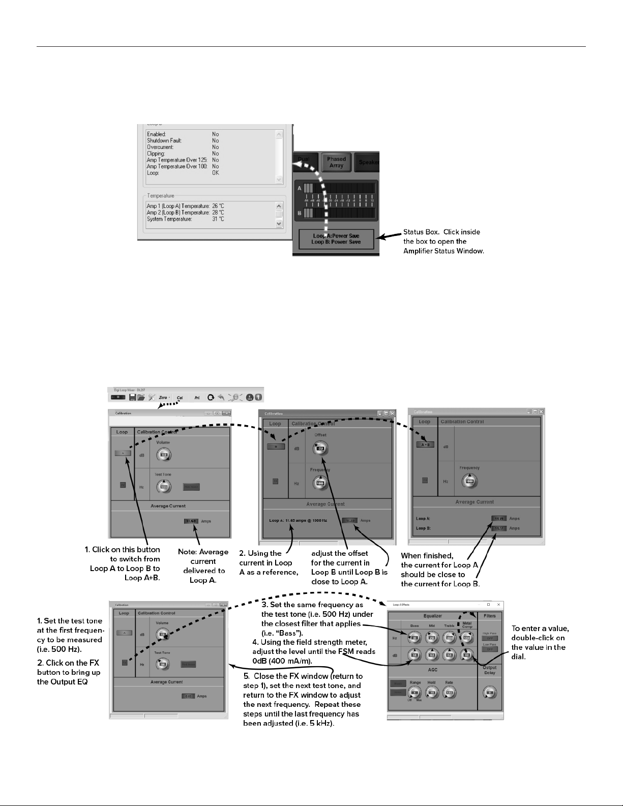
AMPLIFIER STATUS BOX AND STATUS WINDOW
The status box shows loop status at a glance. For more detail, open the Amplifier Status Window by clicking on the box.
Amplier Status Window
CALIBRATION WINDOW
The amplifier must be calibrated to the loop(s) before the VU meters will be accurate. The loop system can then be adjusted to meet the frequency
response requirements as per IEC 60118-4. For the complete procedure on calibrating the amplifier, please refer to the section “Setup and
Calibration Procedure (using a laptop or windows tablet)”. When calibrating a Phased Array, after Loop A has been calibrated with the field strength
meter, switch to Loop B, and adjust the Oset for Loop B until the Average Current for Loop B matches the average current for Loop A. Then
individual test frequencies can be adjusted (i.e. 500 Hz, 1 kHz, 2.5 kHz, etc.) to make the frequency response of the loop meet IEC 60118-4.
Calibration Window (Phased-Array Mode shown)
28
Page 29
DL107, DL207 and DL210 2.0 Digi-Loop™ DSP Induction Loop Amplifiers
*
*
Low Pass
AGC
Filters
Delay
Loop Setup
EQ
Input Mixer
Setup
MuteVol
Out 2: Line
Out 1: Loop A
Input Type
Compression
Setup
Name
EQ
Setup
MuteVolMuteVol
System Configuration
Output Configuration
Input Configuration
In 1: Mic/Line In 2: Line
Configuration Menu
Load Preset
Headphone MonitorLoop Status
MuteVol
Headphone Source
Setup
Setup
MuteVol
Name
Lo
Mid
Hi
Advanced
LPF
MBPF
HPF
Level
Lo Mid Hi
Presets
Ethernet
Security
Power Save
Static IP
IP Address
Subnet Gateway Telnet Port
Set Password PW Timeout
Delay
Tech Tools
Calibrate
Calibrate:
Frequency
Backlight
Metal Comp
Volume
Version
DL107 Name Amp Temp Reset All
Load Preset
Save Preset Change Name
Advanced
High Pass
Mode
etc...
etc...
NET Info
Auto Sleep
Trim Phantom Pwr High Pass
Loop Test
Threshold
Ratio
Attack
Compression
Release
Makeup
Preset
Amount
Hold Time
AGC
Attack
Release
ETHERNET
DANTE
Dante Dev Name
Brightness
EQ
Default=Loop A
or DL207
or DL210
Name
Priority In
ThresholdInput
1 2
2a
3 4
565
7
7a
7b
7c
7d
7e
7f
7a1 7a2 7a3
7b1 7b2 7b3 7b4 7b5
7f1 7f3 7f4 7f5
7d1 7d2
7e1 7e2
7f6
7f1a
7f1b
7f1c
5a
5a1
5a2
5a4
5a3
6a
6b
6c
6d
6e
6f
6g
6c1 6c2
6f1 6f2 6f3 6f4
6f4a
6f4b
6f4c
6f4d
7f2
7f7
6g1
**
5a3
5a3a
5a3b
5a3c
5a3d
5a3e
6d
6d1
6d2
6d3
6d4
6d5
**
7f5a
7f5b
7f5c
7e3 7e4
7f1d
7c1 7c2
Threshold
7e5
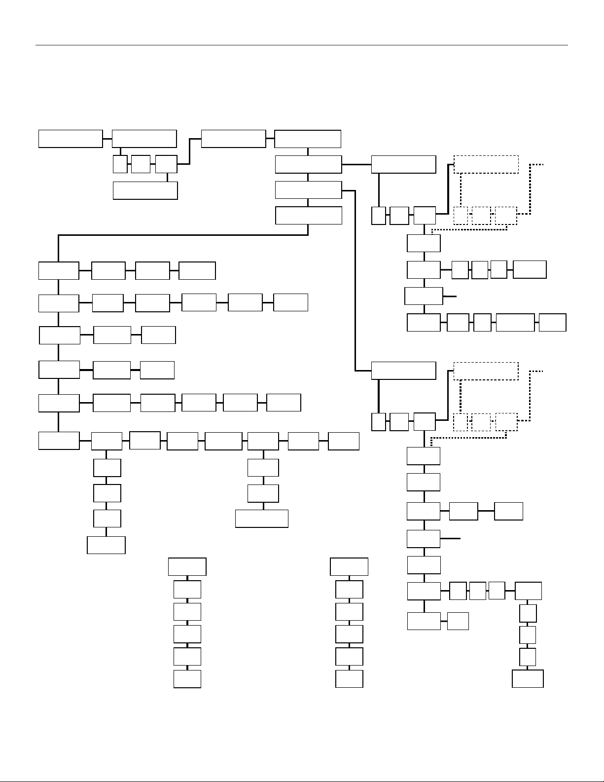
Front LCD Menu
This is a full map of the front menu. Use the numbers next to each box to look up the function in “7a1-3. Presets - Load Preset, Save Preset, Change
Name” on page 34.
29
Page 30
DL107, DL207 and DL210 2.0 Digi-Loop™ DSP Induction Loop Amplifiers
Headphone jack
All aspects of the loop amplifier can be configured from the front panel
GUI.
The on-board menus are navigated and adjusted using a rotary
encoder labeled ADJUST and by pushing the knob in to ENTER.
There are a number of common operations:
To move to the next menu, turn the control clockwise. It might be
necessary to cycle through the on-screen options until you get there.
Clockwise moves forward; counter-clockwise moves back.
Pressing the control knob in ENTER moves the selection into that
menu or option for further adjustment or options.
To change values: ENTER - ADJUST - ENTER.
In order to exit a menu or option, select the BACK command in the list.
The screen will return to the Loop Status menu after a period of time.
Front Panel Controls
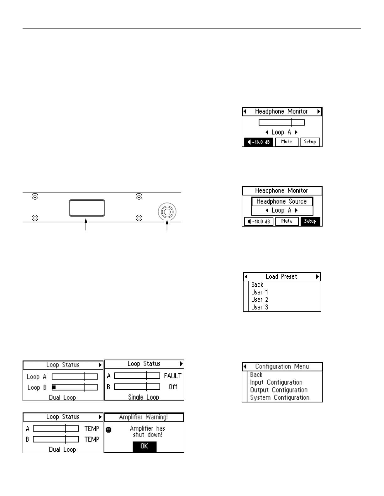
2. HEADPHONE MONITOR
The Headphone monitor can be used to listen to any individual
source or output, or to listen to adjustments as they are made
in the menu. Rotate the knob once to the right to see the
Headphone Monitor screen. The vertical bar going through
the bar graph represents a reference level of 0 dB. You can
change the volume of the headphones or mute the audio from
this screen.
2a. Headphone Source
To change the headphone source, enter the Headphone Monitor
Setup. Rotate the knob to view the sources. Push the knob in to
select the source desired for the headphones.
Front LCD Menu (GUI) display
Menu (GUI) display control knob
Front Screen Menu Tree Detail
The entire on-screen menu is accessed by either rotating the control
knob to the left or right to navigate the menu, or pushing it in to select.
See “Front LCD Menu” on page 29 for an overview of the entire
menu structure.
1. LOOP STATUS
The On-Screen Menu starts, and when it times-out, will return to the
Loop Status Screen. The bars represent the power output of the
loop(s), and will pulse with the audio program being broadcasted
on the loop or speaker. The vertical lines going through the bars
represent the reference level of 0 dB.
Normal Condition: Loop Fault (shorted or open):
Overtemp (loop impedance out of range):
3. LOAD PRESET
Presets provide the ability to save and recall custom
configurations (all amplifier settings). This is where a preset can be
loaded. To save a Preset, see “7a1-3. Presets - Load Preset, Save
Preset, Change Name” on page 34.
4. CONFIGURATION MENU
The configuration menu is where most of the amplifier settings
and fine-tuning is performed. This menu is where Inputs and
Outputs are configured and system parameters are set up, stored
and recalled.
30
Page 31
DL107, DL207 and DL210 2.0 Digi-Loop™ DSP Induction Loop Amplifiers
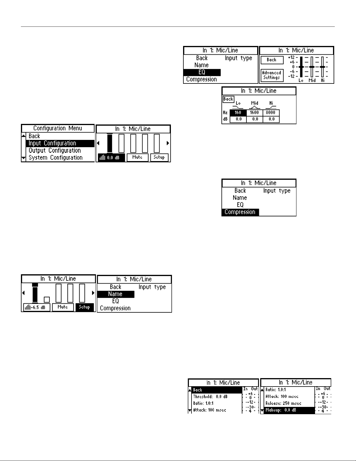
5. INPUT CONFIGURATION
The Input Configuration page allows the user to individually select
and process the incoming signal for all inputs. It does not route
the signal to the outputs. That task is carried out in the Output
Configuration page under the Input Mixer.
From the Loop Status menu, turn the ADJUST rotary control
clockwise to navigate through the Headphone Monitor and Load
Preset menus, to the Configuration Menu. Press ENTER and the
selection moves into the Configuration Menu options. ADJUST
rotary control clockwise to Input Configuration and press ENTER.
Each input is separately adjustable and Input 1 is already selected.
This menu shows an input meter for each of the seven inputs and has
three options for the selected input along the bottom:
• Gain: - press and adjust
• Mute - press to toggle
• Setup - press to enter sub-menu. The available options for
each input are: Name, EQ, Compression, Input Type
5a1. Name
This allows you to name the Input. To change the name, select the
first character and rotate the dial to change letters/numbers. When
the character you want is displayed, push the knob in to select that
character and move to the next position. When finished with the last
character of the name, rotate knob until OK is highlighted; then push
the knob in to save the name.
5a2. EQ
Frequency compensation is available via a 3-band equalizer: Lo
Shelf - Mid Sweep - Hi Shelf. The center (or cuto frequency) for
each band is chosen under Advanced Settigns. The second screen
below shows the level adjustment for each of the bands (low range
highlighted). Rotate the knob until Advanced Settings is highlighted
and push the knob in to select. The 3rd screen below shows the
advanced settings, where the center or cuto frequency for each of
the bands is chosen, as well as slope (in dB) for the cuto.
5a3. Compression
Compression reduces the dynamic range of the input/output,
making soft sounds louder and loud sounds quieter. It has the overall
eect of volume levelling so the entire program is more intelligible to
the listener. Compression has 5 adjustable parameters: Threshold,
Ratio, Attack, Release, and Makeup Gain.
5a3a-d. Threshold, Ratio, Attack, Release, Makeup
Threshold is the level of incoming signal at which compression takes
eect. The Threshold is adjustable from -96.0 dB to 0.0 dB in 0.5dB
steps.
Ratio determines how much compression is applied when it takes
eect. The Ratio is adjustable from 1.0:1 (no compression) to 10.0:1 in
0.1 steps.
Attack is the speed at which compression reacts when the input
signal crosses the threshold. The Attack is adjustable from -0ms to
500ms in 2ms steps.
Release controls the time that the compressor continues to work
after the input signal drops beneath the threshold. Short settings
release the signal quickly, while long release times have the eect
of sustaining the signal. The Release is adjustable from 0ms to
2500ms in 10ms steps.
Makeup Gain is used to bring the overall level of the sound back up,
when the overall volume has been reduced by compression. This
happens when the threshold is set low and/or the ratio has been set
high. The Makeup Gain is adjustable from 0 dB to 40 dB in 0.5db
steps.
31
Page 32
DL107, DL207 and DL210 2.0 Digi-Loop™ DSP Induction Loop Amplifiers
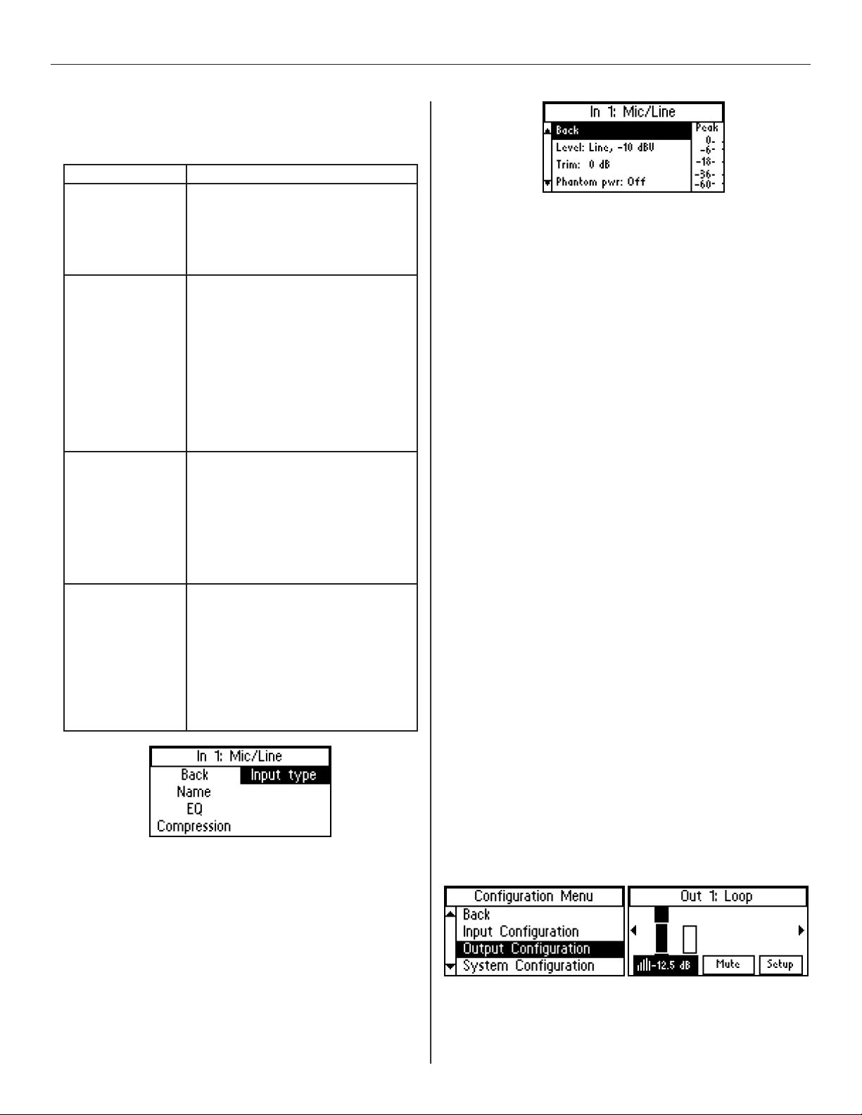
5a4. Input Type
The options for input type vary with the input being set-up. The
options are in the table below.
Input & Type Options
1 & 2
Dante
3 & 4
Analog Mic/Line
5 & 6
Unbalanced Line
7
70/100 V
Hi-pass lter:
• none
• 31 Hz
• 62 Hz
• 125 Hz
• 500 Hz
Level:
• -10 dBU
• + 8 dBU
• +4 dBU
• Mic
Trim Control:
• 12 to 39 dB
Phantom Power switch (only active when Mic type
selected):
48v Phantom power is automatically turned on when
Microphone is selected. Before using the microphone,
check the owner’s manual specifications about the
use of phantom power.
Level:
• -10 dBU
• -4 dBU
High-Pass Filter:
• none
• 31 Hz
• 62 Hz
• 125 Hz
• 500 Hz
Level:
• 25 Vrms
• 70 Vrms
• 100 Vrms
Hi-pass lter:
• none
• 31 Hz
• 62 Hz
• 125 Hz
• 500 Hz
For example, if setting up the Mic/Line inputs, the 3-pin Phoenix
(or XLR) Connector can be programmed to accept various levels:
Line +4dBu, Line +8dBu, Line -10 dBV, or Microphone.
Phantom power is automatically turned on when Microphone is
selected. Before using a microphone, check the owner’s manual
specifications about the use of phantom power.
The Dig In L (or R) input adjustments consist of a High Pass Filter
Crossover Point (frequency) and Attenuation (dB).
Note: The Dig In L and Dig In R inputs are independent, and can
be mixed in the PC App to be routed to separate loops. These
inputs can be switched here, or in the PC App.
5a4a-d. Level, Trim, Phantom Power, High Pass
Level sets the incoming signal level as it applies to the device
being used. There are five possible level settings: Microphone,
Line -10 dBU, Line -4 dBU, Line +4 dBU, and Line +8 dBU.
Trim or Gain This setting is dependent on input level and type
chosen.
• When a Line Level is selected (above), this setting allows
Trim to be adjusted. Trim is adjustable in 3 dB increments from
-6 dB to +57 dB.
• When Microphone Level is selected (above) this setting
allows Gain to be adjusted. Gain is adjustable in 3 dB
increments from +9 dB to +63 dB.
Phantom Power is available as a setting if Microphone Level was
chosen. Phantom power can be turned ON or OFF. When ON it
provides a supply voltage of 48v to the microphone.
High Pass is a high-pass filter with selectable crossover points.
The crossover point can be set to: O, 31 Hz, 62 Hz, 125 Hz or
500 Hz.
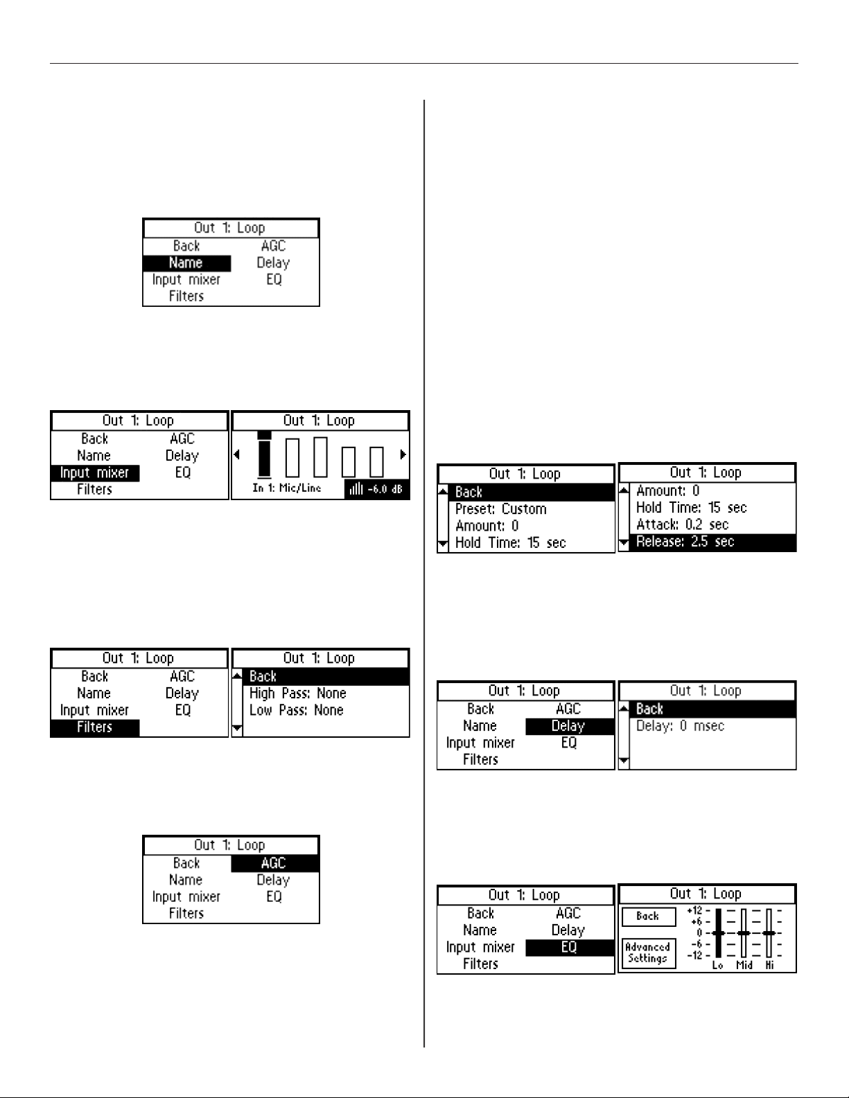
6. OUTPUT CONFIGURATION
The Output Configuration menu controls the signal passing to
loops (and/or loudspeaker when using the DL210), as well as the
line outputs. The loop outputs have comprehensive control, while
the line level outputs have the ability to change the name and
apply EQ.
Each of the outputs can be configured individually. To set up
Output 1, enter Output Configuration. Output 1 is the first input you
can adjust, so it is already selected. To get to the next input, rotate
the knob to the right.
32
Page 33
DL107, DL207 and DL210 2.0 Digi-Loop™ DSP Induction Loop Amplifiers
6a. Name
This allows you to name the Output. To change the name, select
the first character and rotate the dial to change letters/numbers.
When the character you want is displayed, push the knob in
to select that character and move to the next position. When
finished with the last character of the name, rotate knob until OK is
highlighted; then push the knob in to save the name.
6b. Input Mixer
The Input Mixer provides level adjustment of each of the inputs
per each output. This is used when one (or more) input(s)
may be louder or softer than the others. You can use the
headphones plugged into the headphone jack to monitor the
adjustments.
6c. Filters
Filters provide adjustment for a high pass filter and low pass filter
crossover frequency.
High Pass Filter has selectable crossover points at: O (None), 31Hz,
62 Hz, 125 Hz, and 500 Hz.
Low Pass Filter has selectable crossover points at: O (None), 16
kHz, 8 kHz, and 6.3 kHz.
Amount of the AGC can be adjusted to a maximum of 20 dB of
around the calibrated level, or target level. For people familiar
with traditional AGC, the Target is internally set to the calibrated
level and is not adjustable, and the Minimum Level (also called
Threshold) is internally set relative to the calibration target level
and is not adjustable. The calibrated target level is set in Tech
Tools-Calibrate, and this is the level the AGC will attempt to hold.
Hold Time is how long the gain is maintained on signal when the
automatic gain settings take eect. In the Custom preset, the Hold
Time is adjustable from 1 second to 60 seconds in 1 second steps.
Attack is the speed at which the AGC reacts when the level of
the input signal crosses the threshold. Short settings react to the
signal quickly, while long attack times have a lagging eect. In the
Custom preset, the Attack time is adjustable from 0.5 s to 3.5 s in
0.5 s steps.
Release is the amount of time that the AGC continues to work
after the input signal drops beneath the threshold. Short settings
release the signal quickly, while long release times have the eect
of sustaining the signal. In the Custom preset, the Release time is
adjustable from 0.5 s to 3.5 s in 0.5 s steps.
6e. Delay
Delay is the amount of time between the input signal and the
output signal of the amplifier. This is often useful in a loop system
when a PA system is also being used, so that the audio being
heard through the loop via a receiver or hearing aid matches that
of the PA System speakers. Delay helps to eliminate this echo
eect. The Delay is adjustable from 0 ms to 165 ms in 1 ms steps.
6d. AGC
Automatic Gain Control measures the average level of the signal
and applies gain reactively to keep the output level constant. It
also limits the output power and reduces or eliminates distortion
due to clipping that would normally occur without AGC.
6d1-6. AGC Level, Hold Time, Attack, Release
Preset provides default settings for Voice and Music, and only
the Amount is adjustable. A Custom preset allows adjustment of
the Hold Time, Attack, and Release. Voice is designed for pauses
in the audio, where Music is designed for more constant-level
sources.
6f1-3. EQ - Lo, Mid, Hi
The EQ is a Parametric Equalizer. In the basic settings (second
screen, below), there is a low, mid-band, and high frequency slider
that can be adjusted between -12 dB and 12 dB. To review or
change the pole frequencies, see “6f4a-d. Advanced Settings - Lo,
Mid, Hi, Metal Comp” on page 34.
33
Page 34
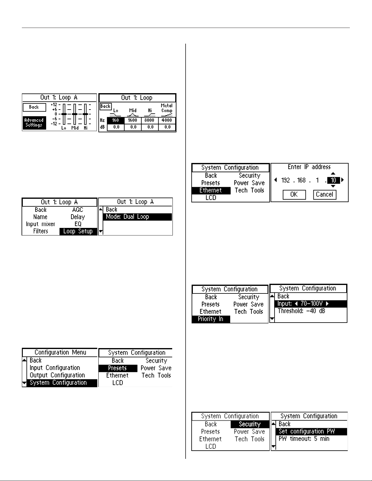
DL107, DL207 and DL210 2.0 Digi-Loop™ DSP Induction Loop Amplifiers
6f4a-d. Advanced Settings - Lo, Mid, Hi, Metal Comp
Advanced Settings provide the ability to change the frequency
point, define a more specific numerical dB level, or adjust for
high-frequency metal loss. The Lo, Mid, and Hi filters can all be
adjusted from 20 Hz to 20kHz, and -12 dB to +12 dB. The Metal
Compensation can be adjusted from 1 kHz to 9kHz, and -12dB to
+12 dB.
6g. Loop Mode (model DL207/210 only)
• Loop Mode configures the outputs for dierent loop/speaker
combinations. Use Dual-Loop Mode to drive a single loop or
two single loops (not overlaid, no phase shift).
• Use Phased Array mode for two overlaid loops in a phased
array layout (where 90° phase-shifting is needed).
• Use Speaker Mode if output A will be used to drive a
speaker, and output B will drive a loop or be left open.
7b1-5. Ethernet
Ethernet provides the ability to specify a static IP Address for the
amplifier, or choose dynamic IP addressing (DHCP).
If using DHCP, you must go to a dierent screen in the menu to
view the router-assigned IP Address is (See “7f. Tech Tools” on
page 35). The DHCP address is not displayed here.
The amplifier must be set up with an IP Address through the front
LCD screen before a networked (or direct-connected) PC can
communicate with it. The PC App won’t work until those settings
are made. If using DHCP, the address needs to be verified
through the Tech Tools-Net Info screen so this address can be
entered into the App, before it will communicate with the amplifier.
In order to use the PC App, the amplifier must be in the same IP
Address range, and subnet, as the PC.
The telnet port defaults to 23 and should not be changed.
Important! If changing from DHCP to a static IP Address, the amplifier
must be powered O, then On, for the new static IP address to take
eect!
7. SYSTEM CONFIGURATION
7a1-3. Presets - Load Preset, Save Preset, Change Name
Presets allow the user to store all of the current amplifier settings
into one easy-to-access Preset, and recall the Preset when
needed. These presets are stored in the amplifier. Three presets
are available as a starting point, with defaults, as shown - DualLoop, Phased-Array, and Speaker/Loop. There are also three
Custom Presets available - User 1, User 2, and User 3. The User
Presets can be renamed. The Dual-Loop, Phased Array and
Speaker/Loop Presets cannot be altered or saved; they can only
be loaded.
We recommend saving the settings in a User Preset in case of
power outage or other catastrophic failure. Settings should be
saved immediately after the system is calibrated.
7c1-2. Priority In
A priority input overrides the current input in use when signal
appears on the priority input. The priority input can be assigned in
the LCD menu.
This feature is useful for overhead announcements or paging
events.
7d1-2. Security - Set Password, Password Timeout
The Security function allows you to set a password and determine
the password timeout delay. The 3-digit access password restricts
unauthorized configuration changes. The password cannot be
recalled or displayed on the screen. The password timeout delay
determines how long the password entry screen will display.
The password can be reset by starting with the unit o, pushing
the knob in and holding it while turning on the amplifier, and
waiting until the screen shows System Password Cleared
(roughly 20 seconds). A reset to factory defaults will also reset the
password, and erase all stored presets and system settings.
34
Page 35
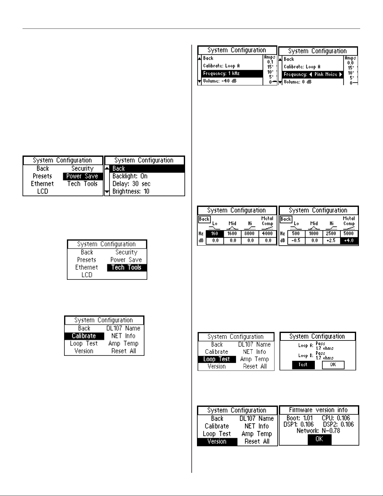
DL107, DL207 and DL210 2.0 Digi-Loop™ DSP Induction Loop Amplifiers
7e1-2. Power Save - Backlight, Delay, Brightness, Auto-
Sleep,Threshold
The power save function will turn the amplifier o after a period
(Auto Sleep Delay) when the input audio level falls below a
specified level (Threshold).
• Backlight can be turned On or O.
• Delay is adjustable in 10 second increments from 10-60
seconds.
• Brightness has 10 levels, from 1-10.
• Auto Sleep Delay is adjustable in 10 minute increments from
10-120 minutes. Default setting is 30 minutes.
• Threshold is adjustable from -80 dB to -30 dB in 1 dB steps.
Default setting is -80 dB.
7f. Tech Tools
Tech Tools provides the ability to calibrate the amplifier through
use of a test tone, perform an open loop test, check the firmware
version(s) of the ICs, name the amplifier, set a static or dynamic IP
address, and reset the amplifier to factory default settings.
Volume of the test tone can be adjusted from -96 dB to 0 dB in 1
dB steps. Once the loop’s response is adjusted to be nearly flat,
volume can be used to adjust the field strength to meet the 400
mA/m (per IEC 60118-4) at the measrement point.
EQ is used to during calibration to adjust the loop output level
at the test frequencies until the loop output at each frequerncy
measures 400mA/m on the field strength meter. It is a 4-pole
parametric equalizer, with a low-pass, band-pass, high-pass and
metal comp filters. For example, when calibrating to 500 Hz, the
Low Pass setting would be adjusted to 500 Hz, and the level
(dB) adjusted until the output of the loop is 400mA/m on the
field strength meter. Then this process is repeated for the next
frequency (i.e. 1 kHz, 2.5 kHz, 5 kHz). The Metal Comp filter allows
additional gain to be added if there is metal loss, as metal loss
tends to aect the higher frequencies in a loop system.
7f1a-d. Calibrate - Calibrate, Frequency, Volume, EQ
This is the tool used to calibrate the amplifier to the loop(s). The
goal during calibration is for the loop’s performance to meet IEC
Specification 60118-4.
Calibrate determines which output (Loop A or Loop B) to send the
test tone to. If calibrating a phased array, loop A will be done first,
and loop B second.
Frequency of the test tone can be set to 100 Hz, 500 Hz, 1 kHz,
2.5 kHz, 5 kHz, or Pink Noise. These test tones are used to
calibrate the amplifier with the use of a field strength meter. If the
levels at dierent frequencies need to be adjusted, the Output EQ
(see below) can be used to raise or lower the output level at that
frequency. On the DL210 2.0, when the amplifier is set to Loop +
Speaker mode, Pink Noise can be used to evaluate the speaker
response with the entire frequency range driven.
7f2. Loop Test
The Loop Test function performs a test algorithm to verify that the
load falls within the acceptable range of 0.5 Ω to 3.0 Ω. If the load
is outside this range the test will show FAULT.
Note that when running a single loop in dual-loop mode, a FAULT
is acceptable for the output with no loop connected. However,
in this case, the unused loop output should be turned o in the
menu.
This tool is to verify that a connected loop does not have an open
break in it.
7f3. Version
Version is an info screen that shows the firmware version of the
bootloader chip, main processor chip (CPU), DSP chip#1, DSP chip
#2 and the Ethernet card firmware version.
35
Page 36
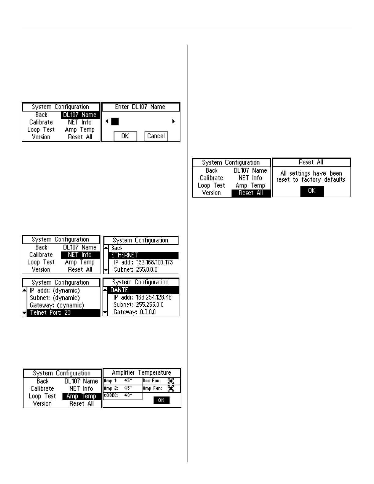
DL107, DL207 and DL210 2.0 Digi-Loop™ DSP Induction Loop Amplifiers
7f4. DL107/207/210 Name
The DL107/207/210 Name provides the ability to give the amplifier
an 8-character name for easy identification when connecting to
it through the PC App on a network. This name will show up on a
drop-down list in the PC App as an available device to connect to.
For example, if 5 amplifiers were connected on the network, and
the third amp was designated for the Ballroom, you could connect
to the Ballroom amplifier to make changes to that amp’s settings.
7f5. NET Info
This screen is for viewing Ethernet and Dante parameters of the
amplifier. No changes can be made from this screen.
Four parameters can be viewed here: (1) Ethernet Address and
MAC address of the ethernet card, (2) Ethernet Address and MAC
address of the Dante card, (3) the Dante Card Name, and (4) the
Default Dante Card Name. To set the ethernet parameters, see
“7b1-5. Ethernet” on page 34. To set the DL107/207/210 Name,
see “7f4. DL107/207/210 Name” on page 36. To set the Dante
parameters, use Dante Controller. (For more information about
installing/using Dante controller, please visit Audinate’s website:
https://www.audinate.com/products/software/dante-controller).
7f7. Reset All
This resets all of the settings back to factory defaults - except the
Ethernet and Dante Network Settings. Any other user-entered
information will be lost. The amplifier may need to be rebooted
after the factory reset is performed to change states. For example,
if the amplifier goes to sleep it may still be asleep until it gets
rebooted.
Note: The PC App gives the user the ability to save all settings
to a configuration file for recall later. In this manner, all settings
can be erased (here) to bring the amplifier back to a known
state (factory defaults) for troubleshooting purposes, etc. Then if
desired, a saved configuration can be loaded back into the unit
via the PC App. It is good practice to store backup configurations
in a configuration file if much work has been done to finely adjust
the amplifier.
7f6. Amp Temp
The temperature of the two amplifier output stages and the
CODEC (audio processor chip) can be monitored here. A zz by the
temperature means that the amplifier is in sleep mode (see “7e1-2.
Power Save - Backlight, Delay, Brightness, Auto-Sleep,Threshold”
on page 35 for how to adjust when the amplifier goes to sleep).
36
Page 37

Specications
DL107 NET, DL107 NET D, DL207 NET, DL207 NET D
Dimensions 1 RU Rackmount, 19” W x 1.75” H x 10” D. Chassis is 17” W.
Weight
Color Case: Black, white and blue legends on front, white legends on back. LCD: Backlit Blue.
Fan cooling
Power supply
Heat output @ 120 VAC
Ethernet (1x) RJ-45; 10-100 MBps.
USB (1x) standard-B. USB 1.1, 2.0 or 3.0 supported.
Environment 0-35° C ( 32-95° F), 0-90% relative humidity,
Coverage area
Dante input On “D” models only. (1x) RJ-45;100 Mbps. Minimum latency: 2 ms. Audio sample rates supported: 44.1, 48 kHz. Resolution: 24 bits.
Line inputs
Mic/Line inputs
70-100 V input (1x) 2-position terminal block; high/speaker-level input (accepts 25 V, 70 V or 100 V) from distributed audio/paging systems.
Line outputs
Loop output(s) (1x) 2-position terminal block per output
Audio output delay Adjustable from 0 to 165 msec
Headphone output (1x) 1/4” stereo headphone jack, on front of unit. Monitored input or output selectable in menu.
Loop fault relay (1x) 3-position terminal block providing NC, NO and Common. Contact rating: 2.0 A @ 30 VDC.
Loop output drive voltage 16.1 Vrms (22.8 Vpk) continuous
Rated loop output current 9.5 Arms (13.4 Apk) per output
Loop resistance range 0.5 Ω to 3.0 Ω (DC)
Rated load 0.5 Ω DC with 135 µH inductance
Frequency response 45 Hz to 9.0 kHz ± 2 dB (1 kHz ref.)
Rated loop THD <1 % at rated output current (1 kHz sine wave).
DL107: 9.2 lbs (4.2 kg)
DL207: 9.2 lbs (4.2 kg)
Variable Speed, Temperature Controlled
Internal, Universal 100-240 VAC, 50/60 Hz, 200 Watt. Fuse: 5 x 20 mm, 5 A, 250 V.
AC power plug is IEC 320-C14.
DL107 : Sleep State: 63 BTU/hr; Idle State: 71 BTU/hr; Driving one loop @ 9.5 A: 339 BTU/hr
DL207: Sleep State: 63 BTU/hr; Idle State: 84 BTU/hr; Driving two loops @ 9.5 A each: 638 BTU/hr
DL207 (dual output amplifier):
30,000 sq. ft. (2,786 sq. m.) (Perimeter Loops, 3:1 aspect ratio, both outputs driven)
18,000 sq. ft. (1,672 sq. m.) (Perimeter Loops, 1:1 aspect ratio, both outputs driven)
DL107 (single output amplifier):
15,000 sq. ft. (1,393 sq. m.) (Perimeter Loop, 3:1 aspect ratio)
9,000sq. ft. (836 sq. m.) (Perimeter Loop, 1:1 aspect ratio)
(1x) 3-position terminal block, 10 kΩ input impedance. Configurable/accepts -10 dBV, -4 dBu, +4 dBu, +8 dBu, balanced or
unbalanced. Level adjustable 0 to -96 dB.
(1x) XLR 3-pin jack. Input impedance: 1.5 kΩ Mic, 10 kΩ Line. Configurable/Accepts: Mic, Line -10 dBV, Line +4 dBu, or Line +8 dBu,
balanced or unbalanced. Phantom supply (24 V).
(1x) 3-position terminal block; loop-through of Mic/Line Input 1 & Line Input 2, +4 dBu, Balanced or Unbalanced. The line outputs
mirror the audio of the loop output.
DL107, DL207 and DL210 2.0 Digi-Loop™ DSP Induction Loop Amplifiers
GENERAL
INPUTS
OUTPUTS
AUDIO
37
Page 38

DL107, DL207 and DL210 2.0 Digi-Loop™ DSP Induction Loop Amplifiers
DL210 NET and DL210 NET D
Dimensions
Weight
Color
Fan cooling
Power supply
Heat output @ 120 VAC
Ethernet
USB
RS-232/Loop fault relay
Environment
Coverage area
Dante input
Mic/Line inputs
70-100 V input
Line outputs
Loop output(s)
Audio output delay
Headphone output
Loop fault relay
Loop output drive voltage
Rated loop output current
Loop resistance range
Speaker output
Rated load
Loop frequency response
Rated loop THD
Front controls
Adjustable settings
Internal calibration tools
Other features
Network control & rmware
Warranty
Approvals
Standards compliance
2 RU Rackmount, 19” W x 3.5” H x 12” D. Chassis is 17” W.
14.3 lbs (6.5 kg)
Case: Black, white and blue legends on front, white legends on back. LCD: Backlit Blue.
Variable Speed, Temperature Controlled
Internal, Universal 100-240 VAC, 50/60 Hz, 250 Watt. Fuse: 5 x 20 mm, 5 A, 250 V.
AC power plug is IEC 320-C14.
Sleep state: 100 BTU/hr; Idle state: 146 BTU/hr; Driving two loops @ 12 A each: 1,040 BTU/hr
(1x) RJ-45; 10-100 MBps.
(1x) standard-B. USB 1.1, 2.0 or 3.0 supported.
(1x) DB-9 jack. RS-232: Pin 2=Tx, Pin 3=Rx, Pin 5=gnd. Loop fault relay: Pin 1=NC, Pin 4=Common, Pin 6=NO. Relay contact rating: 2.0
A @ 30 VDC.
0-35° C ( 32-95° F), 0-90% relative humdity.
31,400 sq. ft. (2,917 sq. m.) (Perimeter Loop, 1:1 aspect ratio, both outputs driven)
51,660 sq. ft. (4,800 sq. m.) (Perimeter Loop, 3:1 aspect ratio, both outputs driven)
INPUTS
DL210 NET D 2.0 model only. (1x) RJ-45;100 Mbps. Minimum latency: 2 ms. Audio sample rates supported: 44.1, 48 kHz. Resolution:
24 bits.
(2x) 3-position terminal block, input impedance=1.5 kΩ Mic, 10 kΩ Line. Configurable/Accepts: Mic, Line -10 dBV, Line +4 dBu, or Line
+8 dBu, balanced or unbalanced. Phantom supply (48 V).
(1x) 2-position terminal block; high/speaker-level input (accepts 25 V, 70 V or 100 V) from distributed audio/paging systems.
OUTPUTS
(1x) 3-position terminal block; loop-through of Mic/Line Input 1 & Line Input 2, +4 dBu, Balanced or Unbalanced. The line outputs
mirror the audio of the loop output.
(1x) 2-position terminal block per output
Adjustable from 0 to 165 msec
(1x) 1/4” stereo headphone jack, on front of unit. Monitored input or output selectable in menu.
Integrated into RS-232 DB-9 jack. Pin 1=NC, Pin 4=Common and Pin 6=NO. Contact rating: 2.0 A @ 30 VDC.
33.3 Vrms (47.1 Vpk) continuous
12 Arms (17 Apk) per output
0.5 Ω to 3.0 Ω (DC)
Integrated into Loop Output A terminal block (switchable in menu). 225 Watts x 1 channel @ 4 Ω, 125 Watts x 1 channel @ 8 Ω, (Class
D). Frequency response = 20 Hz - 20 kHz, THD=0.07%.
AUDIO
0.5 Ω DC with 135 µH inductance
45 Hz to 9.0 kHz ± 2 dB (1 kHz ref.)
<1 % at rated output current (1 kHz sine wave).
OTHER
Front LCD display menu access/adjustment via control button/dial.
Input mixing, parametric equalization, compression, metal loss compensation, high and low-pass filters, AGC and audio delay, output
levels. See User Manual for adjustment range(s).
Test tone generator with pink noise, loop current adjustment/matching. See User Manual for details.
Save/load configuration, loop test, priority input selection with adjustable threshold, loop fault relay, open/short and thermal
protection.
Function control and calibration by DigiLoop PC App via ethernet (RJ-45). PC App requires Windows 7 or higher.
Firmware updates through USB only.
2 years
CE, UL, ULC, FCC, Industry Canada, RoHS, WEEE, CB scheme, RCM
This product is designed to meet the IEC-60118-4 standard when correctly designed, installed and commissioned.
Test Specifications provided to the IEC 62489-1 standard.
38
Page 39

DL107, DL207 and DL210 2.0 Digi-Loop™ DSP Induction Loop Amplifiers
Resources
- Manuals, Specications, Firmware and Loop Certication Forms can be downloaded from our website.
-Loop System Designs are provided at no charge to authorized dealers, distributors or integrators who have a specific projects with signed
contracts. Once a design request form is received by our Tech Blue Department (available on our website), these designs are created.
- Technical Support is provided by our Tech Blue Department from 8:00 a.m. - 4:30 p.m. Central Time. You can reach us by calling 800.328.6190
(Ask for TechBlue) or send an email to [email protected].
Warranty
Williams AV products, a brand owned by Williams AV, are engineered, designed, and manufactured under carefully controlled conditions to provide
you with many years of reliable service.
Williams AV warrants the DL107 NET, DL107 NET D, DL207 NET, DL207 NET D, DL210 NET 2.0, and DL210 NET D 2.0 Digi-Loop™ DSP
Induction Loop Amplifiers against defects in materials and workmanship under normal use and conditions for 2 years from date of purchase.
This warranty is available to the original end purchaser of the product and CAN BE transferred to subsequent purchasers of the product.
Microphones, earphones, headphones, batteries, chargers, cables, carry cases, and most other accessory products carry a 90-day warranty.
Williams AV has no control over the conditions under which this product is used. Williams AV, therefore, disclaims all warranties not set forth
above, both express and implied, with respect to the DL107 NET, DL107 NET D, DL207 NET, DL207 NET D, DL210 NET 2.0, and DL210 NET
D 2.0 Digi-Loop™ DSP Induction Loop Amplifiers, including but not limited to, any implied warranty of merchantability or fitness of use of
such equipment including, without limitation, any warranty that the use of such equipment for any purpose will comply with applicable laws
and regulations. Williams AV shall not be liable to any person or entity for any medical expenses or any direct, incidental or consequential
damages caused by any use, defect, failure or malfunctioning of the product, whether a claim for such damages is based upon warranty,
contract, tort or otherwise, the sole remedy for any defect, failure or malfunction of the products is replacement of the product. No person
has any authority to bind Williams AV to any representation or warranty with respect to the DL107 NET, DL107 NET D, DL207 NET, DL207
NET D, DL210 NET 2.0, and DL210 NET D 2.0 Digi-Loop™ DSP Induction Loop Amplifiers. Unauthorized repairs or modifications will void the
warranty. This warranty is void if damage occurred because of misuse, or if the product has been repaired or modified by anyone other than
a factory authorized service technician. Warranty does not cover normal wear and tear on the product or any other physical damage unless
the damage was the result of a manufacturing defect. Williams AV is not liable for consequential damages due to any failure of equipment to
perform as intended. Williams AV shall bear no responsibility or obligation with respect to the manner of use of any equipment sold by it.
This warranty does not cover reimbursement for your costs of removing and transporting the product for warranty service evaluation or installation
of any replacement product provided under this warranty.
The exclusions and limitations set out above are not intended to, and should not be construed so as to contravene mandatory provisions of
applicable law. If any part or term of this Disclaimer of Warranty is held to be illegal, unenforceable, or in conflict with applicable law by a court of
competent jurisdiction, the validity of the remaining portions of this Disclaimer of Warranty shall not be aected, and all rights and obligations shall
be construed and enforced as if this Limited Warranty did not contain the particular part or term held to be invalid. The terms of the warranty are
governed by the laws of the State of Minnesota.
Prices and the specifications of the products are subject to change without notice.
For Complete Warranty Statement go to: www.williamsav.com/warranty-statement
NOTICE: Williams AV products are NOT designed for use in extreme temperature, humidity or chemical environments. The introduction of
chemicals such as chlorine, salt water or human sweat into the product will cause damage to the circuitry. Damage due to these causes is NOT
covered under the Product Warranty.
If you experience diculty with your system, call Toll-Free for Customer Assistance 1-800-843-3544 (U.S.A.) or +1 952 943 2252 (Outside the U.S.A.)
If it is necessary to return the system for service, your Customer Service Representative will give you a Return Authorization Number (RA) and
shipping instructions.
39
Page 40

WilliamsAV.com
MAN 202M-0223
U.S. | 800.843.3544 [email protected] INTL | +1.952.943.2252 [email protected]
© 2022, Williams AV, LLC
 Loading...