

Page 1

Wireless Broadband IP Video
Surveillance System
Version 1.1
Support 1-800-000-0000
Page 2

Contents:
Chapter 1
About your new product
Chapter 2
Hardware and Software Requirements
Chapter 3
Equipment
Chapter 4
Basic information that you need to know
Chapter 5
Configuration
Cradlepoint
Dyndns
I-net Secureview
Chapter 6
Support
Basic Troubleshooting
Who to contact in case of a problem
Chapter 7
Warranty Information
2
Page 3

Chapter 1 – About your new product
Device highlights
• User Friendly Applications
• Simply to configure
• Digital I/O Port
• Ability to use any equipment
• Specialized Application Support
• Multiuse Environment
• Ability to See, Store and Capture Images (Live)
• Email Notification
• Lower Purchase Cost
• Cheaper to operate
This is an IP Based Video Surveillance System. Applications for this product are free and do not
require any additional purchases they are built into the device as part of the device. Cradlepoint
and I-net Secureview software makes configuration and maintaining the product easy.
Combining the Digital I/O with different sensors makes this a one of a kind device. Using any
device such as a motion sensor, infrared, radar you are able to set this up to provide instant
notification as well as send data to your cell phone, email address, or pager. With our ability to
use Wireless Broadband, WIFI, or LAN we can produce live images at remote sites as well and
setup a trigger to notify you as an alarm would. While developing the product we found that we
could combine different technologies to produce one product that works with all of them.
Sample applications
• Police
• Ambulance
• Remote Locations
• Difficult Locations
• Time and Triggered Events
• Email Notifications
• Cell Phone Alerts
• Etc…
3
Page 4

Chapter 2 – Hardware and Software Requirements
Installation and Configuration
To configure for the first time you will need to have a computer or a laptop that can
communicate via a wireless connection and TCP/IP. This is standard on most latops today.
Wireless Broadband
Wireless Broadband 2.1.0 Compatibility List
Sprint Verizon AT&T Alltel
USB:
Franklin CDU-550
Franklin CDU-680
Novatel U720
Novatel U727
Sierra Wireless 595U
Sierra Wireless C597
(Compass 597)
USB:
Novatel USB720
Novatel USB727
Sierra Wireless 595U
UTStarcom UM150
(Pantech UM150)
USB:
Sierra Wireless 881U
Sierra Wireless 875U
USBConnect 881
USB:
UTStarcom UM150
(Pantech UM150)
Computer
Used for I-net Secureview Software
• Intel 1.5 GHz or above
• 128MB Ram
• Windows 2000, XP or Vista
• 4MB VGA Video Card (24 bit true color display)
• 100MB free hard disk space
• 10/100 Ethernet
• Microsoft Internet Explorer 6 or above
• Multi Channel Recording mode, requires the HDD transfer rate must be 66MB or above
Cameras
Any CCTV camera using a BNC connection
Digital I/O
4
Page 5

Chapter 3 – Equipment
Equipment included as part of your system.
• IP Based Video Surveillance Box
• Camera
• Power Supply
• 3ft BNC Cable
• M-M Power Cable for Camera
• I-net Secureview Software
• PDF Files with a Setup Guide, User Manual, Secureview Manual, and Cradlepoint
Manual.
Optional Equipment
• Wireless Broadband
• SD memory card (4MB or 16MB)
• Computer
<<<Picture of Equipment >>>
5
Page 6
Chapter 4 – Basic Information that you need to know
Getting to know your Video Surveillance Box.
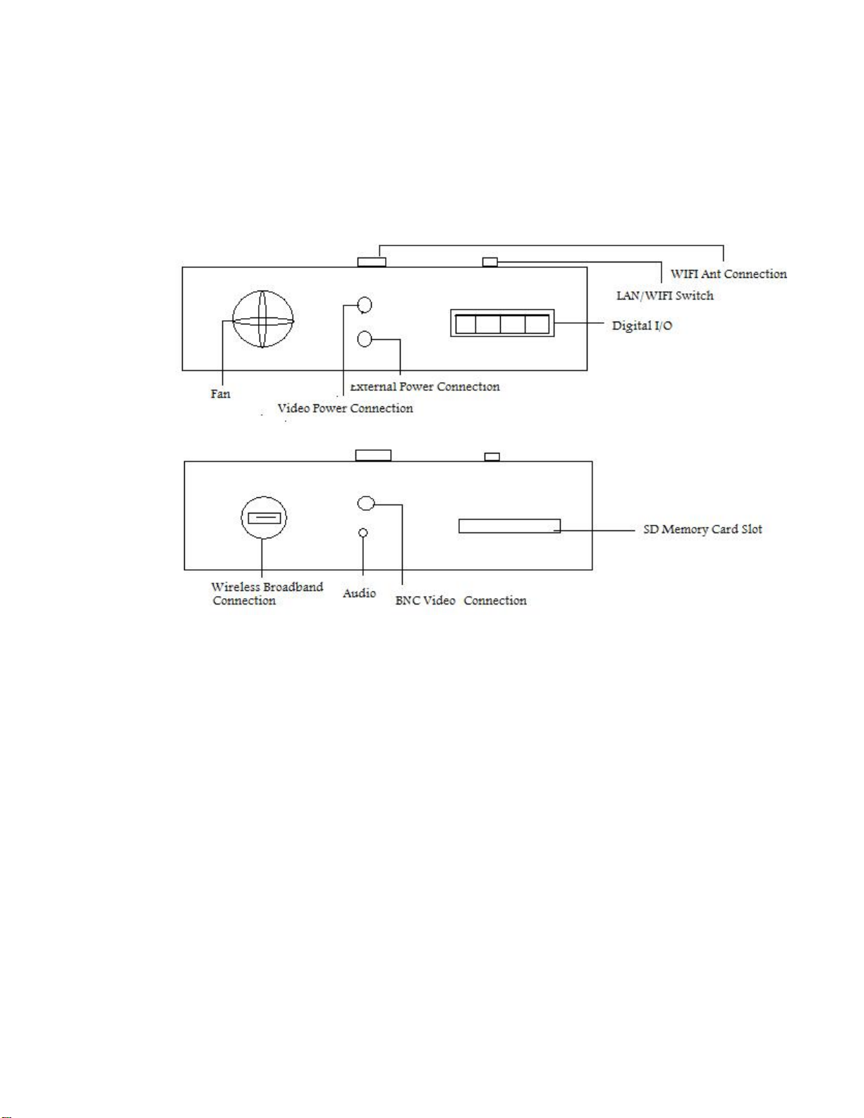
Description of Connections
1. Fan – Used to maintain an ideal operating temperature.
2. External Power Connection – This is where the supplied power supply is connected.
3. Video Power Connection – Using the M-M connector supplied with the kit will allow
you to run power for the video camera from this device.
4. Digital I/O – Allows for optional devices such as external motion detectors, alarms and
pan and tilt capabilities.
5. LAN/WIFI switch – Using this switch allows you to set how you want to use this
device.
6. WIFI Antenna Connection – Can be used with external antenna for internal network
applications.
7. USB Wireless Broadband Connection – Only to be used with approved equipment.
Refer to recommended list from Chapter 2.
8. BNC Video Connection – Used for connecting cameras of your choice.
9. Audio Plug-in – This can be used for recording audio. Not recommended due to amount
of free space available for recording video to your SD memory card.
10. SD Memory Card Slot – You can use any SD Memory Card that is not greater than
16MB. The bigger the card the more available storage space that is available to video.
6
Page 7

Description of terms
ISP – Also knows as a Internet Service Provider, companies such as ATT, Verizon, Sprint and
other local providers, assign you internet device an TCP/IP address. This address can be either
static or dynamic.
LAN – Local Area Network
TCP/IP – This is the internet protocol that is used for most LAN and all of the Internet.
SMTP – Simple Mail Transfer Protocol, this is used for sending and receiving emails.
WIFI – Wireless network connection.
DNS – Domain Name Server – These are used by the internet to translate IP address to a name.
Example: www.yahoo.com could translate to 10.136.58.23
Subnet Mask – This allows you to create your own internal network. Typically the default will
be set to 255.255.255.0 which allows for 254 different IP addresses or 254 computers and
devices.
MAC Address – This is a number that is assigned by the manufacturer based on equipment type.
An easy way to think about it, consider it a serial number assigned by the manufacturer. This will
be found on the bottom of the Wireless Surveillance device.
Dynamic IP Addressing – This is where an ISP assigns you a IP address. This address can
change and could break your ability to see your camera. There are companies that provide
Dynamic DNS Services.
Static IP Addressing – The ISP assigns a unique IP address for the device you are using and it
will never change.
7
Page 8

Chapter 5 – Configuration
There are 3 parts to making the Video Surveillance Device to work. We will step thru each piece
to get your camera online.
• Configure the wireless router
• Working with and Configuring the Dynamic DNS software
• Configure the I-net Secureview software
How to configure the Cradlepoint Router Software
1. Connect to the wireless router portion of the device.
2. Open Internet Explorer.
3. Connect to the router via a TCP/IP connection.
4. Login to the router.
Connecting to the wireless router
1. Located in the bottom right hand corner is a icon with 2 computers with a red X on it.
Move your mouse over the icon and click on this one time, this will bring a popup box
telling you there is Wireless networks are available. Click on Connect to a network. Each
computer maybe a different.
2. This will provide a new screen, which will list all available networks.
8
Page 9
3. You will want to select the one that begins with CT-XXX (XXX – will be the last 3 digits
of the MAC Address).
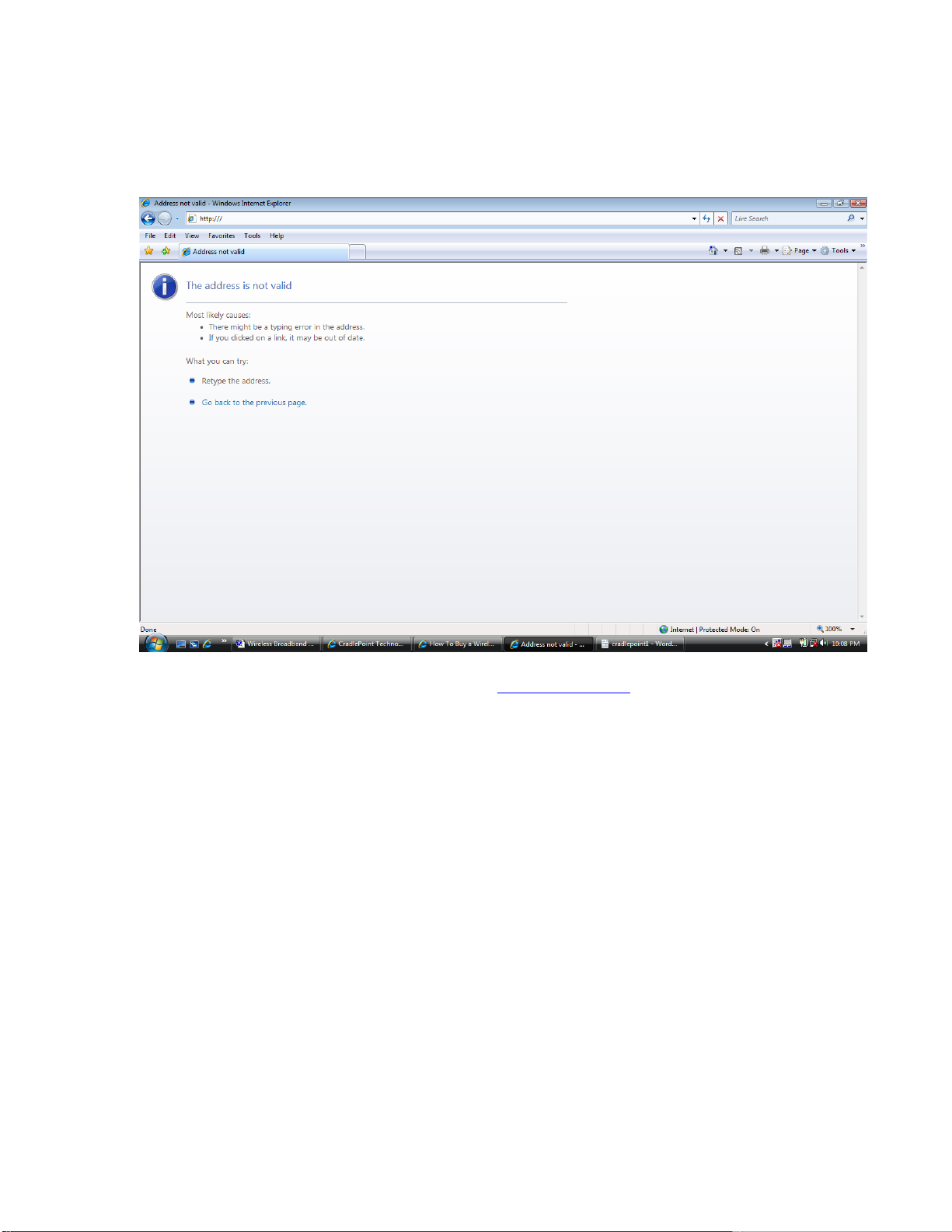
4. Open Internet Explorer. You will see a screen like below.
5. In the address line type in the following http://192.168.0.1 and hit enter.
6. This will take you to the wireless router login screen. See image on the next page.
9
Page 10
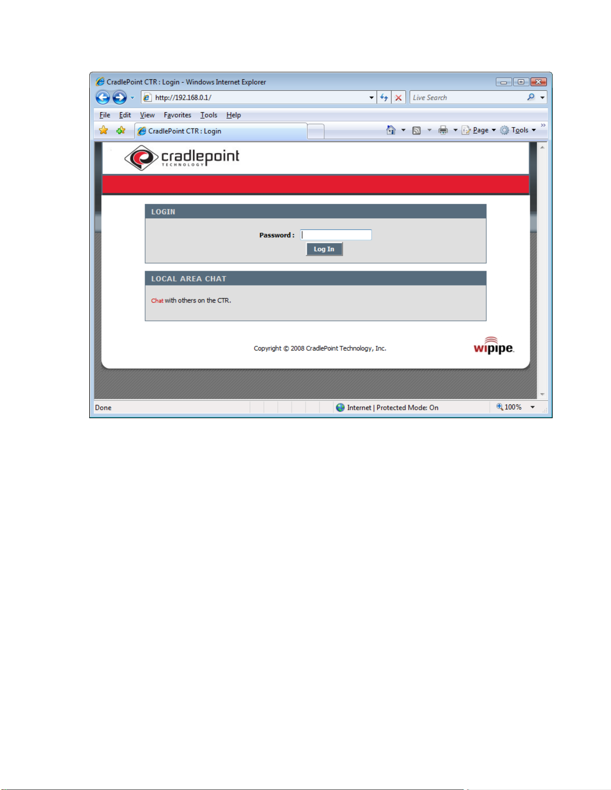
7. To login to the router the Password is different. You will need to refer to the MAC
Address on the bottom of the device. Taking the last 6 characters of the address and
typing those in and hitting the login button. If you do not get into the software verify your
password.
8. This will bring you to the Internet Connection Wizard.
10
Page 11
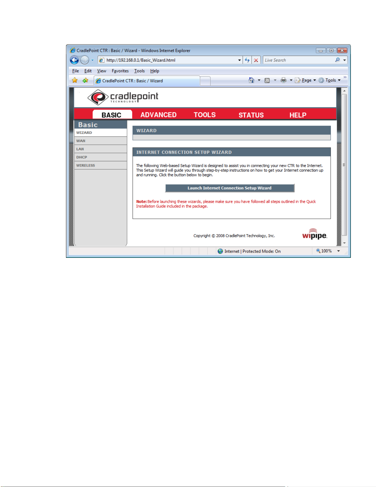
9. Click on the Launch Internet Connection Setup Wizard.
11
Page 12

10. The Setup Wizard screen it tells you the steps that you will need to perform to complete the initial setup of
the wireless router. Click on Next to continue.
12
Page 13

11. Setting a password and time zone screen. This screen allows you to create a unique
password for your wireless router. You will want to set the correct time zone, this is
important for any video that you want to have time stamps on. Once completed click on
NEXT to continue.
13
Page 14

12. Select Cellular Phone or USB Modem. Using the defaults at this point we have
configured the wireless router to use the Wireless Broadband devices listed in Chapter 2.
Click on NEXT to continue.
14
Page 15

13. Configure security and name your network screen. This screen allows you to change the
name of the router and increase the type of security for wireless with WEP or WPA
(stronger encryption, requiring that any computer that connects to the router, to be known
either by a special passphrase or a MAC Address. Make sure that the Require User Login
box is checked and click on NEXT to continue.
15
Page 16

14. This completes the initial setup of the wireless router. Attach your Wireless Broadband
device and click on Connect. This will cause the router restart and save the settings.
15. There are some specific settings that we need to setup once the router has rebooted. The
next sections will give you the steps needed to complete that task.
16. Reconnect and login to the router as outlined in steps 1- 7.
17. After login click on STATUS. This will bring you the Device Info screen.
18. You want to write down the information that is located in the IP Address line.
____ . ____ . ____ . _____
This information is necessary in future steps and sections.
16
Page 17

19. Click on the Basic section and click on DHCP section. We want the IP Address listed for
INETSERVER.
_____._____._____._____
17
Page 18

20. Click on the tab ADVANCED and the section listed as firewall. Click on the Enable
DMZ and on the drop down section where it says Select Machine. On this section hit the
down arrow and scroll down to INETSERVER and select. This should change the DMZ
IP Address, if it doesn’t take the information from step 19 and type it into the address
box.
18
Page 19

That concludes the basic router setup and we are ready to move on to the next section which is
how to setup the Dynamic DNS, for our purposes we will use the Dyndns service.
19
Page 20

Creating a Dynamic DNS Account
We are using the service of Dyndns for our purposes of this example. Most of the services that
are available will be pretty close to the same type of setup and information required. For
accounts that will require more than 5 unique DNS names you will need to sign up for an
account.
1. Open Internet Explorer and in the address line type
2. http://www.dyndns.com and hit the enter key. This will
take you to the following screen.
3. Click on Create Account.
20
Page 21

4. Fill out all required information. Once you have completed that you will receive an email
with further instructions on how to activate your account.
We will jump ahead as if you have already received your email and are at the point to
login and setup your 1st Dynamic DNS Account.
21
Page 22

5. Click on Add Host Services
22
Page 23

6. Create a name you would like to call the host and type it into the Hostname box, click on
the down arrow until you reach the one called dyndns.org.
7. Service Type needs to be set to Host with IP address.
8. Under the IP Address box type in the number that you wrote down from page 17. Make
sure the Mail routing box is unchecked. Then click on the Create Host button at the
bottom of the page.
9. Last step to complete the setup so the information can be seen by your computer and on
the internet. You will need to login into the wireless server again. Open Internet Explorer
and in the address line type http://192.168.0.1
and login again.
23
Page 24

10. Enter the information that you created on the Dyndns website, making sure that you
include the username and your password so that the site will update with any changes in
the IP address.
11. Save settings and close Internet Explorer.
12. Check your work at this point by opening Internet Explorer and type in the address line
your newly created host name. It should look something like this
http://abc123.dyndns.org if it is correct you will be able to see the internet version of I-
net Secureview.
24
Page 25

Configure I-net Secureview
There are 2 sections for this software. There is the computer based version and the Internet based
version which is already built into the Video Surveillance Box.
Computer Based Version of Secureview
• Username – Admin
* Password – inetcam
Internet Version of Secureview
• Username – Admin
* Password – inetsev
We will only cover the basic setup of getting one camera setup. To setup more then one camera
you would just repeat the setup for each box you want to connect via the broadband wireless.
1. Install the software that was included with your system.
2. Follow all of the defaults to do the basic installation. This will create a I-net Secureview
icon.
3. After clicking on the icon and starting the application login using the username and
passwords provided above.
25
Page 26

This is the opening screen that you will see when you first login. This is referred to as the
monitor screen and gives you the ability to watch from one to thirty two cameras.
Here is a list of what the icons at the top of the screen do.
The three main buttons that we will review are the Monitor, Review and Settings.
Monitor is pretty self explainitory and gives you the ability to view live data. As well as
monitoring any alarms that occur. The Group section allows you change which cameras that you
can look at. This is done by dragging onto the viewing area.
Review / Playback
26
Page 27

In this section you are able to review recordings that have been made by any triggers or alerts
that have be setup. By choosing the segment based on the time and hitting the play button on the
Playback section you can review what occurred. The Playback section also allows you to take a
snapshot of a frame for printing.
27
Page 28

Settings
This is where the important part of the configuration occurs. You will need to do several things
to get your camera online.
Below is a listing of the secondary menu items. We will go thru them and show you what needs
to be done to see your cameras.
28
Page 29

Steps to add a camera.
1. Click on add group
2. Name the group so it will be easy to recognize for in the future. You can create multiple
groups and add cameras to the specific groups.
3. Once you have type in the group name hit ok and it will add it to the group list on the left
hand side of the screen.
4. The next icon in the list is delete the group. To remove a group click on the group name
and hit this icon to remove.
5. Next we will add a camera. By clicking on the add camera icon it will prompt you for
which group you would like to add it to. Click on the down arrow and select the group.
29
Page 30

6. This is where the information that you created when you setup an account at the
DYNDNS website is important. You will want to place that information into the address
section. Click on the NEXT button to continue.
7. The system will prompt you for the password. This password should be inetsev. Click on
NEXT.
30
Page 31

8. Once the camera is found you can change a couple of things. Main item would be the site
name, it is easier to set a name that is specific to the site as opposed to leaving it the
default. Click NEXT to continue.
31
Page 32

9. This now shows all of the information populated. At this point you are able to setup
triggers, drag and drop it into the monitor screen and record video at this point. If you are
looking for a continuous recording you can at this point click on the START REC button
and this will begin to record.
This is an example of a single group with one camera.
32
Page 33

Here is an example of multiple groups with several different cam eras assigned to the different
groups. On the bottom left of the screen you can see several listings there. This is where event
triggers are listed and can be reviewed under the playback screen.
This concludes the basic configuration and setup of a single camera on this Secureview software.
33
Page 34

Chapter 6:
Support:
Support should come from the Local Dealer that you made the
purchase from.
Basic Troubleshooting:
If the unit does not power up.
Make sure you are using the Power Adapter that was provider with
unit.
Can’t Login to wireless network.
The SSID should be the LAST 6 Digits of the Routers MAC
Address.
LAN port does not work.
Make sure the switch is set to the correct location.
Can’t connect to Internet through Air Card.
Make sure you have activated your account and Air Card.
Who to contact in case of problems.
Should you need further help that your dealer cannot provide.
you can email support@watchfirevideo.com
34
Page 35

Regulatory Information
FCC Statement
This equipment has been tested and found to comply with the limits for a Class A digital
device, pursuant to Part 15 of the FCC Rules. These limits are designed to provide
reasonable protection against harmful interference in a residential installation. This
equipment generates, uses, and can radiate radio frequency energy and, if not installed and
used in accordance with the instructions, may cause harmful interference to radio
communications. However, there is no guarantee that interference will not occur in a
particular installation. If this equipment does cause harmful interference to radio or
television reception, which can be determined by turning the equipment off and on, the user
is encouraged to try to correct the interference by one or more of the following measures:
• Reorient or relocate the receiving antenna.
• Increase the separation between the equipment and receiver.
• Connect the equipment into an outlet on a circuit different from that to which the
receiver is connected.
• Consult the dealer or an experienced radio or television technician for help.
Changes or modifications not expressly approved by the party responsible for
compliance could void the user's authority to operate the equipment.
35
Page 36

Chapter 7:
Warranty:
Is provide for 1 year from date of purchase: You must fill out your
Warranty Card for this to be in affect.
36
 Loading...