

Page 1

INSTRUCTION MANUAL
16P-3005-101
March, 1982
Including procedures for…
• Operation
• Auditing
• Adjustment
• Diagnostics
For service…
NOTE NEW TOLL-FREE
TELEPHONE NUMBERS:
800-621-1253
3401 N. California Av.
Page 2

ROM SUMMARY
ROM PART NO. DESCRIPTION
ROBOTRON 1B A-5343-09898 PROM, 4Kx8
ROBOTRON 2B A-5343-09899 PROM, 4Kx8
ROBOTRON 3B A-5343-09900 PROM, 4Kx8
ROBOTRON 4B A-5343-09901 PROM, 4Kx8
ROBOTRON 5B A-5343-09902 PROM, 4Kx8
ROBOTRON 6B A-5343-09903 PROM, 4Kx8
ROBOTRON 7B A-5343-09904 PROM, 4Kx8
ROBOTRON 8B A-5343-09905 PROM, 4Kx8
ROBOTRON 9B A-5343-09906 PROM, 4Kx8
ROBOTRON 10B A-5343-09907 PROM, 4Kx8
ROBOTRON 11B A-5343-09908 PROM, 4Kx8
ROBOTRON 12B A-5343-09909 PROM, 4Kx8
Decoder ROM 4 (Horizontal) A-5342-09694 PROM, 512x8
Decoder ROM 6 (Vertical) A-5342-09821 PROM, 512x8
Video Sound ROM 3 A-5343-09910 ROM, 4Kx8
Special Chip 1 A-5410-09911 Special Chip
Page 3

POWER TURN-ON
CAUTION - This game must be plugged into a properly grounded outlet to prevent shock hazard and to ensure proper game
operation. DO NOT use a "cheater" plug to defeat the ground pin on the line cord, and DO NOT cut off the ground pin.
WHEN THE GAME IS FIRST TURNED ON it produces a sound. Simultaneously general illumination should come on
and a moment later a scanning “rug pattern”' indicating the RAM test should appear on the screen. Next the rug should
become stationary as the ROM test is performed. In a correctly running game the rug pattern will be followed by the message
"INITIAL CHECKS INDICATE: OPERATIONAL". If RAM or ROM failure messages come up on the screen instead, refer
to Power-Up Tests in TROUBLESHOOTING PROCEDURES.
GAME OPERATION
GAME START - Insert coins; a random sound is produced and credits are displayed on the CRT. With one or more credits
displayed, pressing 1-player start initiates a l-player, *3-turn game. With two or more displayed, pressing 2-player start
initiates a 2-player, *3-turn game.
PLAYER CONTROLS
MOVE JOYSTICK (LEFT) maneuvers mutant clone (our hero) in any of eight directions: N-NE-E-SE-S-SW-W-NW.
FIRE JOYSTICK (RIGHT) fires anti-robot laser gun in same eight directions.
GAME PLAY
ROBOTS ARE THE ENEMY - The player (represented by the mutant clone) must deactivate six types of robots with a laser
gun. However the robots' armada including tanks, electrodes and cruise missiles will be deployed against the mutant.
Meanwhile defenseless normal clones must be protected by the mutant or they will be captured and reprogrammed by the
robots. Arriving at 25,000* points (or any multiple of 25,000), the mutant is awarded a new opportunity to defend his clonekinsmen.
HIGH SCORE SIGNATURE
Select letters with the MOVE joystick. Push up to move forward through the alphabet; pull down to move backward. Then
push the FIRE joystick up to lock in the letter.
BOOKKEEPING AND EVALUATION TOTALS
1. In Game-Over Mode, open the cashbox and depress the cashbox advance switch. The advance switch located on the
coin door can also be used. The CRT should indicate all bookkeeping and evaluation totals. If so, go to step 3. If the
CRT display comes up in the ROM test, perform step 2.
2. Continue to depress the cashbox advance switch, stepping the game through test programs for ROMs, RAMs, CMOS
RAMs, color RAMs, sounds, switches, and then CRT test patterns, of which there are five. The fifth test pattern, color
bars, directly precedes the CRT display of the bookkeeping and evaluation totals.
3. The bookkeeping and evaluation totals appear on the displays as in Figure 1.
CLEARING BOOKKEKPING TOTALS
1. Depress ADVANCE to display Game Adjustments.
2 Operate MOVE joystick to position cursor on CLEAR BOOKKEEPING TOTALS.
3. Push FIRE.
4. Depress ADVANCE.
* Adjustable feature
Page 4

BOOKKEEPING TOTALS
LEFT SLOT COINS 167
CENTER SLOT COINS 0
RIGHT SLOT COINS 426
PAID CREDITS 593
EXTRA MEN EARNED 221
PLAY TIME IN MINUTES 1200
MEN PLAYED 2000
CREDITS PLAYED 593
AVERAGE TIME PER CREDIT 2:01
AVERAGE TURNS PER CREDIT 3.37
Figure 1. Bookkeeping display
GAME ADJUSTMENTS
In the Game-Over Mode open the coin door with AUTO-UP, and depress the coin door ADVANCE switch twice to cause a
CRT display as shown in Figure 2.
To select and then set functions to the desired values, use the MOVE (UP-DOWN) joystick to select the that is to be changed
and then, making sure the coin door is open, use the FIRE (UP-DOWN) joystick to increase or reduce the value of the selected
function.
The number of turns per game can be set anywhere from 1 to 20 (3 recommended). Difficulty is factory-programmed at 5
(moderate; recommended). It can be custom-programmed as desired.
Game pricing is selected with standard settings or with custom settings as shown in Tables 1 & 2. Table 1 lists some common
pricing schemes and directs the reader to the proper entry in Table 2, which shows what the CRT display should look like to
accomplish the desired pricing. Note that free play can be elected by entering the code number 9 at the PRICING
SELECTION function (see Tables 1 and 2).
For standard settings you need change only the PRICING SELECTION. For custom settings, first set PRICING SELECTION
to zero and then set the remaining values according to Table 2.
Page 5

GAME ADJUSTMENT
EXTRA MAN EVERY 25000 RECOMMENDED
TURNS PER PLAYER 3 RECOMMENDED
PRICING SELECTION 3 1/QUARTER 4/DOLLAR
LEFT SLOT UNITS 1
CENTER SLOT UNITS 4
RIGHT SLOT UNITS 1
UNITS REQUIRED FOR CREDIT 1
UNITS REQUIRED FOR BONUS CREDIT 0
MINIMUM UNITS FOR ANY CREDIT 0
FANCY ATTRACT MODE YES
DIFFICULTY OF PLAY 5 RECOMMENDED
LETTERS FOR HIGH SCORE NAME 3 RECOMMENDED
RESTORE FACTORY SETTINGS NO
CLEAR BOOKKEEPING TOTALS NO
HIGH SCORE TABLE RESET NO
AUTO CYCLE NO
SET ATTRACT MODE MESSAGE NO
SET HIGH SCORE NAME NO
USE -MOVE- LEVER TO SELECT ADJUSTMENT
USE -FIRE- LEVER TO CHANGE THE VALUE
PRESS ADVANCE TO EXIT
Figure 2. Game Adjustment
Highest Score Signature
The number of letters allowed the highest scoring player for entering his name can be varied from 3 to 20 and is recommended
as 3. If objectionable words are entered as the signature name, you can change the lettered entry leaving the highest score the
same. See Setting Highest Score Name.
Restore Factory Settings
1. Position the cursor on RESTORE FACTORY SETTINGS.
2. Push FIRE.
3. Depress ADVANCE.
Resetting High Score Table
1. Position the cursor on RESET HIGH SCORE TABLE.
2. Push FIRE.
3. Depress ADVANCE.
Setting Attract Mode Message
1. Position the cursor on SET ATTRACT MODE MESSAGE.
2. Push FIRE.
3. Depress ADVANCE.
4. Enter up to two lines of your message following instructions on the screen
5. Depress ADVANCE to terminate process.
NOTE:
To restore the Williams attract mode message, it is necessary to
perform steps 1 through 3 and then turn the game OFF then ON.
Setting High Score Name
1. Position the cursor on SET HIGHEST SCORE NAME.
2. Push FIRE.
3. Depress ADVANCE.
4. Enter new signature; depress ADVANCE to terminate process.
NOTE:
An alternate, simpler method enters the factory highest score signature. In the game over mode, hold HIGH SCORE
Page 6

Table 1. Pricing Schemes
TABLE 2
COIN DOOR MECHANISM CREDITS/MONEY
STANDARD SELECTION/
CUSTOM KEY
Twin Quarter
Quarter, Dollar, Quarter
1DM, 5DM 1/1DM, 6/5DM 2
20-Cent, 50-Cent 1/20¢, 3/50¢ F
1 Franc, 5 Franc 1/2F, 3/5F 4
25 Cent 1/25¢, 4/1G 6
1 Guilder 1/25¢, 5/1G G
5 Franc 1/5F, 2/10F 7
10 Franc 1/10F 8
1 Franc, 2 Franc 2/1F 5/2F 2
100 Lire, 200 Lire 1/200 Lire 8
Twin Coin 1/1 Coin
1 Unit, 5 Unit 1/2, 3/5
FREE PLAY - 9
1/25¢, 5/$1
2/50¢, 5/$1
1/25¢, 4/$1
2/50¢, 4/$1
1/50¢, 3/$1, 4/$1.25
1/50¢, 3/$1, 7/$2
1/50¢, 3/$1, 6/$2
1/50¢
1/2 Coins
1/3 Coins, 2 5 Coins
1/1, 5/5
1/3, 2/5
A
B
3
C
D
E
1
5
3
5
H
4
I
J
FUNCTIONS
Pricing Selection
Left Slot Units
Center Slot Units
Right Slot Units
Units per Credit
Units for Bonus Credit
Minimum Units for Credit
Table 2. Pricing Settings
STANDARD SELECTION
1
2
3
4
5
6
1
6
1
1
1
1
4
0
4
16
4
0
1
1
1
6
1
4
2
1
1
2
2
1
4
0
0
0
0
0
0
0
0
0
0
0
CUSTOM KEYDISPLAY
A B C D E F G H I J
7
8
9
0
0
0
0
0
0
0
0
0
0
1
1
1
1
1
1
3
12
6
1
2
1
2
0
0
4
4
4
4
12
48
0
0
0
0
0
2
2
1
1
1
1
3
12
15
4
2
5
10
1
2
1
1
1
1
4
14
5
1
5
1
5
0
0
0
4
4
0
15
96
0
4
0
0
0
0
0
0
0
2
2
0
24
0
0
0
0
0
Page 7
TROUBLESHOOTING PROCEDURES
Certain types of game malfunctions may inhibit the game's diagnostic or display faculties. Troubleshooting procedures for most of
these types of malfunctions as well as malfunctions that permit self-diagnosis are covered below. Our troubleshooting algorithm
begins with Power-Up and continues until Game Over Mode. All procedures can be performed with minimal test equipment or
merely by observing the game itself.
POWER-UP TESTS
NO GENERAL
ILLUMINATION
(1) Check fuse F2 on power supply board.
(2) Check for proper installation of jumpers
W1, W2, W3 and/or resistor R27. (Some
machines DO NOT have an R27. Refer to your
drawing set.)
(3) Check 4P1/J I, 4P3/J3, 6P2/J2 and 6P3/J3.
(4) If all the above don't turn up the problem
check power supply board.
(1) Open back doors
(2) Press reset button on CPU Board.
(3) Try RAM and ROM tests (see below).
(4) If all the above don't turn up the problem,
check power supply board.
NO INITIAL VIDEO
(RUG PATTERN)
CHECKING POWER
SUPPLY BOARD
(1) Swap power supply board with one from
known-good game.
(2) If game plays, problem is on power supply
board.
(3) If game doesn't play, check power
transformer with voltmeter.
(4) If known-good power supply is unavailable
for tests above, check +5V, – 5V and + 12V
outputs on power supply in game. Each
MUST BE within 2% of rated output.
MORE POWER-UP TESTS
ROM BOARD
TEST
GENERAL “0” means all
CMOS
(See Appendix A)
BATTERY
(See Appendix A)
MEMORY
PROTECT
INTERLOCK
(See Appendix A)
SPECIAL CHIP “0” means tests
LEDS
RECOGNIZE
CONDITION
power-up tests
passed
“0” means tests
passed
“0” means tests
passed
“0” means tests
passed
“0” means tests
passed
passed
ROM BOARD
LEDS
IDENTIFY
CHIPS
- (1) Scanning rug pattern
(2) Stationary rug pattern
(3) "INITIAL TESTS INDICATE:
OPERATIONAL"
(4) Game-Over Mode
- “HIGH SCORE TABLE RESET”
“BOOKKEEPING TOTALS CLEARED”
“ADJUSTMENT FAILURE”
“RESTORE FACTORY SEITINGS BY
OPENING FRONT DOOR AND
TURNING GAME OFF AND ON”
- “FACTORY SEITINGS RESTORED” (2) Press ADVANCE. Game should
- “HIGH SCORE TABLE RESET”
“BOOKKEEPING TOTALS CLEARED”
“ADJUSTMENT FAILURE”
“RESTORE FACTORY SEITINGS BY
OPENING FRONT DOOR AND
TURNING GAME OFF AND ON”
- “HIGH SCORE TABLE RESET”
“BOOKKEEPING TOTALS CLEARED”
“ADJUSTMENT FAILURE”
“RESTORE FACTORY SEITINGS BY
OPENING FRONT DOOR AND
TURNING GAME OFF AND ON”
- (1) Scanning rug pattern.
(2) Blank screen instead of “INITIAL
TESTS INDICATE: OPERATIONAL”
(3) High score table with no scores.
(4) Intro blank or program crash.
VIDEO REMEDY
If any video (see left) is missing or
error message is displayed, proceed to
Diagnostic Mode tests.
(1) Open coin door and turn power
off and on.
return to Game-Over Mode.
(1) Open coin door and turn power
off and on. Or press ADVANCE. In
either case, game should return to
Game-Over Mode.
(2) Check AA alkaline cells on CPU
Board.
(3) If problem persists proceed with
CMOS RAM test by putting the game
into its Diagnostic Mode (see SELFDIAGNOSTICS).
(1) Making and breaking coin door
interlock switch, check with VOM
and replace if faulty.
(2) Replace if faulty: Memory protect
gates 6E, IC1, Ql, or CMOS RAM
1C.
(1) Turn power off.
(2) To find bad chip replace 2 special
chips one at a time with known good
chips.
(3) Turn Machine on after each
replacement and run through PowerUp Tests.
Page 8

SELF DIAGNOSTICS
If RAM or ROM failure messages are displayed on the CRT after the “rug pattern” proceed with self-diagnostics. Selfdiagnostic procedures are controlled by the AUTO-UP/MANUAL-DOWN and ADVANCE switches in the coin door. Set the
AUTO-UP/MANUAL-DOWN switch to the MANUAL-DOWN position and depress the ADVANCE pushbutton. The game
is now in its Diagnostic Mode and a ROM test is performed. With ROM test results present on the CRT display, depressing
the ADVANCE pushbutton initiates the RAM test. Further tests (CMOS, sound, switch, color RAM, monitor test patterns) are
encountered one after the other as the ADVANCE pushbutton is depressed (once more for each subsequent test).
MONITOR TEST PATTERNS - For ease in monitor adjustments, the monitor may be slid back and the screen viewed in a
mirror. Remove the two bolts and carefully slide the monitor back in its shelf; secure the monitor in the extended position by
inserting the two bolts though holes in the monitor base and monitor shelf provided at the left side of the monitor.
AUTO CYCLE MODE - From the color bar pattern (or Game Over with the switch set to AUTO-UP) depress ADVANCE
two times to display GAME ADJUSTMENTS.
1. Position the cursor on AUTO CYCLE with the MOVE Joystick and push the FIRE joystick up.
2. Depress ADVANCE.
3. The system will now sequence through ROM, RAM, and CMOS RAM tests repeatedly. The coin door must be open
during the Auto Cycle test. If an error is detected, the test is terminated and the failure indication is displayed on the
CRT.
4. To terminate the Auto-Cycle test, turn the game OFF and ON.
Figure 3. RAM Location and Numbering on the CPU Board
(See above)
Page 9

DIAGNOSTIC MODE RAM AND ROM TESTS
ROM BOARD
TEST
ROM “2” means ROM
RAM “1” means RAM
CMOS
(See Appendix A)
SPECIAL CHIP - No – indicated
LEDS
RECOGNIZE
CONDITION
error.
error.
“3” means CMOS
RAM error
ROM BOARD
LEDS
IDENTIFY
CHIPS
2-digit ROM
chip number
Bank number
first . . . then
chip number in
bank (see figure
3)
-
by CRT display
in color test
only.
VIDEO REMEDY
“ROM ERROR” and ROM chip no. (1) Turn power off.
(2) Replace suspected chip.
“RAM ERROR” followed by RAM
bank number and chip number (Note:
with multiple RAM failures this
display may not appear)
(1) Check for normal voltages on
indicated RAM chip: -5v/pin 1,
+12v/pin 8, +5v/pin 9.
(2) Turn power off.
(3) Replace suspected chip.
(4) With multiple RAM failures
always check power supply. See
POWER-UP TESTS.
“CMOS RAM ERROR OR WRITE
PROTECT FAILURE”
(1) Check pin 22 of CMOS RAM
for +3.8VDC. If present, replace
CMOS chip 1C. If absent replace
AA alkaline cells.
(2) With new alkaline cells, check
for +3.8VDC. If still absent,
replace diodes D9 and D10.
(3) Upon power-up and re-entry
into diagnostics if CMOS error
message persists replace memory
protect gates 6E, IC1, Ql and
address decoder 4G/6J.
Thick vertical band indicates color
RAM fault
Replace 1 B, 2B or color analogue
circuit. If both RAMs appear bad,
may actually be flip-flop 1A See
Table 3 and Figure 4 for details.
COLOR RAM TEST - TEST 4
(1) CRT SEQUENCES THROUGH
COLORS, 2 SECONDS EACH
(2) VERTICAL BAND INDICATES
COLOR RAM FAULT.
Figure 3. Color Test
Table 3. Which Color RAM is Bad?
FAULTCOLOR
SEQUENCES
1 Light red
2 Red
3 dark red
4 Light green
5 Green
6 Dark green
7 Light blue
8 Blue
9 Dark blue
4 Light green Green band Dark green band or
5 Green Light green band Dark green band or
6 Dark green - Grey band
RAM 1B RAM 2B
Too-light or too dark
Magenta band
red or gray band
Yellow band Cyan band
Magenta band Too-light or too dark
blue or gray band
gray band
gray band
Page 10

MORE DIAGNOSTIC TEST MODES
Tests 5 and 7 provide sequential subtests. To stop automatic cycling set switch to MANUAL-DOWN. Depress ADVANCE in
MANUAL-DOWN to step through subtests.
SOUND TEST - TEST 5
From color RAM test, depress ADVANCE in AUTO-UP.
SWITCH TEST - TEST 6
CRT indicates AUTO-UP closed and any stuck switches.
Set black coin door switch to MANUAL-DOWN and clear
any stuck switches. CRT should indicate no switches
closed. Operate switches and check for display of switch
name.
Table 4. Tracing the Missing Sound
Test sequences, sound lines 1 through 6:
Missing Check
1
2
3
4
5
6
All
2P4/lOP3 Pin 3
2P4/10P3 Pin 2
2P4/10P3 Pin 5
2P4/10P3 Pin 4
2P4/10P3 Pin 7
2P4/10P3 Pin 6
Perform sound board diagnostics
Table 5. CRT Display for Each Switch
Coin Door Player Panel
ADVANCE
AUTO-UP
HIGH SCORE RESET
LEFT COIN (next to hinge)
CENTRE COIN
RIGHT COIN'
SLAM SWITCH
1- PLAYER START
2- PLAYER START
MOVE UP
MOVE DOWN
MOVE LEFT
MOVE RIGHT
FIRE UP
FIRE DOWN
FIRE LEFT
FIRE RIGHT
MONITOR SET UP TEST PATTERNS - TEST 7
From Switch Test depress ADVANCE in AUTO-UP. The
color bar pattern is also analyzed to detect color RAM
faults. If color RAM Test 4 indicates no faults, a doublewidth band, half width bands, transposition or missing
bands indicates a fault in 1A, 1B, 2B or 2C chips.
Table 6. Patterns Indicate Problems
Pattern Alignment/Adjustment
Cross Hatch
Red
Green
Blue
Color bars
1 2 3 4 5 6 7 8
Vertical and Horizontal Linearity,
Convergence, Focus
}
} Color Purity
}
1 = RED
2 = GREEN
3 = BLUE
4 = WHITE
5 = BLACK
6 = YELLOW
7 = CYAN
8 = MAGENTA
Figure 4. Color Bar Pattern
SOUND BOARD DIAGNOSTICS
Depress the DIAGNOSTIC pushbutton on the bottom of the Sound Board. A check is made of the Sound ROM and sounds
are produced if the check is good. If sounds are produced but not in Audio Test 5 check for ROM board PIA output on Sound
Board inputs that are stuck low. If no sound is produced either the Sound ROM, IC12, input power, or other Sound Board
circuitry is faulty.
Page 11
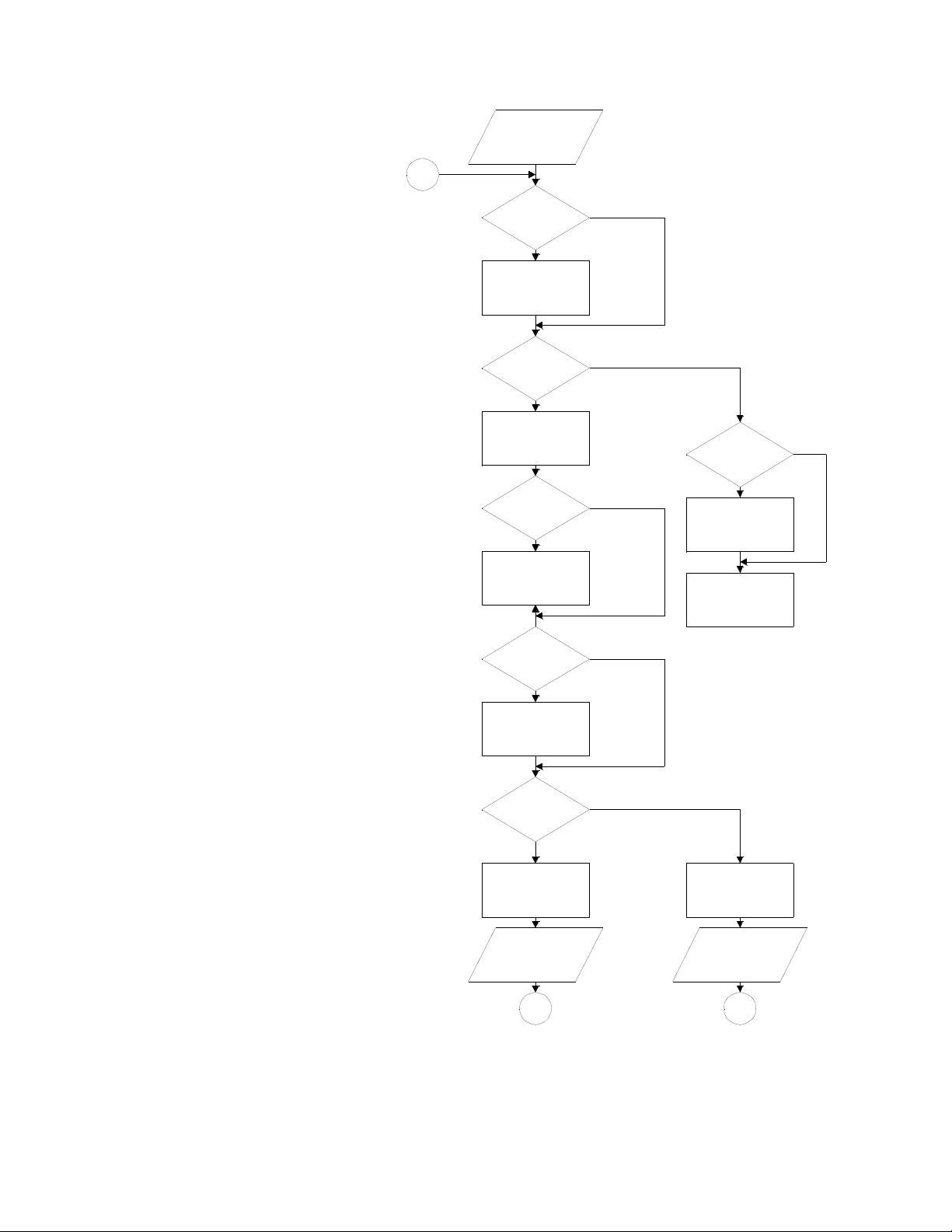
CMOS RAM Data Test Protocol
cause interference in which case the user at his own expense will be required to take whatever
The first sub-test of the CMOS RAM
data is that of the ATTRACT MODE
MESSAGE checksum. If the test does
not pass, the factory ATTRACT MODE
MESSAGE is restored. Next, the game
adjustments are checked and restored to
factory settings if an error is found. If
game adjustments are found intact, the
high score table is checked for any bad
entries. Bad entries are replaced with a
score of 4,000 points and no initials. If
all entries check, the game returns to the
Game Over Mode.
If game adjustments are restored to
factory settings, the AUDIT TOTALS
are checked. If 5 or more audit digits
are other than 0-9 (that is hexadecimal
A through F) all audit totals are cleared.
This is followed by a check of the high
score table and the table is reset to
factory settings if errors are found.
Finally, game adjustments are rechecked
and either OPEN COIN DOOR or
FACTORY SETTINGS RESTORED is
displayed. With the former, open the
coin door and turn the game OFF and
ON and then FACTORY SETTINGS
RESTORED will be displayed. Return
to game over by depressing the
ADVANCE pushbutton or by turning
the game OFF and ON a second time.
APPENDIX A
POWER ON
1
ATTRACT MODE
MESSAGE?
RESTORE
FACTORY
MESSAGE
GAME
ADJUSTMENTS?
RESTORE
FACTORY
SETTINGS
AUDITS?
CLEAR
AUDITS
HIGH
SCORE
TABLE?
RESET HIGH
SCORE TABLE
TO FACOTRY
SETTINGS
PASS
FAIL
PASS
FAIL
PASS
FAIL
5 OR MORE HEX A-F
PASS
FAIL
HIGH
SCORE
ENTRIES?
FAIL
BAD ENTRIES
REPLACED WITH
4,000 AND NO
INITIALS
"INITIAL TESTS
INDICATE ALL
SYSTEMS GO"
DISPLAYED
PASS
FAIL
PASS
"FACTORY
SETTINGS
RESTORED"
DISPLAYED
POWER ON
AND OFF
GAME
ADJUSTMENTS?
"OPEN COIN DOOR"
DISPLAYED
OPEN COIN
DOOR
POWER OFF
AND ON
1 1
“Warning: This equipment generates, uses, and can radiate radio frequency energy and if not
installed and used in accordance with the instructions manual, may cause interference to radio
communications. As temporarily permitted by regulation it has not been tested for compliance
pursuant to Subpart J of Part 15 of FCC Rules, which are designed to provide reasonable
protection against such interference. Operation of this equipment in a residential area is likely to
 Loading...