

Page 1
WWW.WILLIAMS-REFRIGERATION.COM
OPERATING MANUAL FOR NATURAL REFRIGERANT
CABINETS
IMPORTANT INFORMATION (PLEASE RETAIN THIS DOCUMENT)
This Manual covers the installation, operation and routine maintenance requirements for the
following Williams Refrigeration products:
Williams Medi+ Range
Please read this Manual carefully before connecting the appliance.
Provided the instructions in this Operating Manual are read and implemented correctly, the
optimum performance and reliability of your equipment should be maintained.
We assume the installer, user and service provider are appropriately trained, skilled and
competent to properly and safely carry out the work, and will use the necessary safety
equipment, and take the necessary precautions required of their intended work.
Improper installation, maintenance or repair may put the user at considerable risk.
Williams cabinets are available in a choice of temperature ranges.
Temperature parameters are set as follows:
High Temperature (H) +2°C (35.6°F) / +8°C (46.4°F)
Low Temperature (L) -18°C (0°F) / -22°C (-8°F)
General Regulations
Declaration of Conformity:
Refrigerant Designation Global Warming Potential
HC - R290 3
HC - R600a 3
Williams Refrigeration declares that all products manufactured by Williams Refrigeration comply with the
applicable directives, and those products are therefore declared to be in conformity with the provisions of
the above legislation.
Model No.: ...............................................................................
Serial No.: ................................................................................
Batteries Producer Registration Number: BPRN06225
Page 2
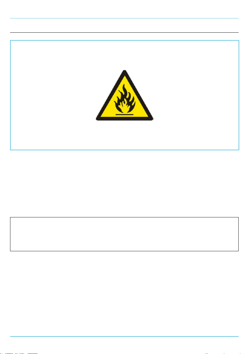
IMPORTANT REFRIGERATION AWARENESS
IMPORTANT REFRIGERATION AWARENESS
WARNING
SYSTEM CHARGED WITH FLAMMABLE REFRIGERANT
REFRIGERANT:R290 / R600A (REFRIGERANT GRADE PROPANE AND ISOBUTANE
RESPECTIVELY ONLY)
Ensure all operatives are aware the appliance contains an environmentally friendly but ammable
refrigerant.
Technical Safety and Advice
All appliances are only to be installed by persons who are appropriately trained, skilled and competent to
properly and safely carry out the work, and serviced by qualied engineers for the handling of hydrocarbon
refrigerants
Ensure procedures are adhered to in the following Operating Manual.
Should a suspected leak become apparent, immediately evacuate the area and remotely
switch o the cabinet.
DO NOT remove the plug from the socket as this could act as a source of ignition. Leaking
refrigerant may ignite and cause injuries.
Contact Williams Refrigeration on +44 (0) 1553 817 000, stating the suspected fault.
2
Page 3
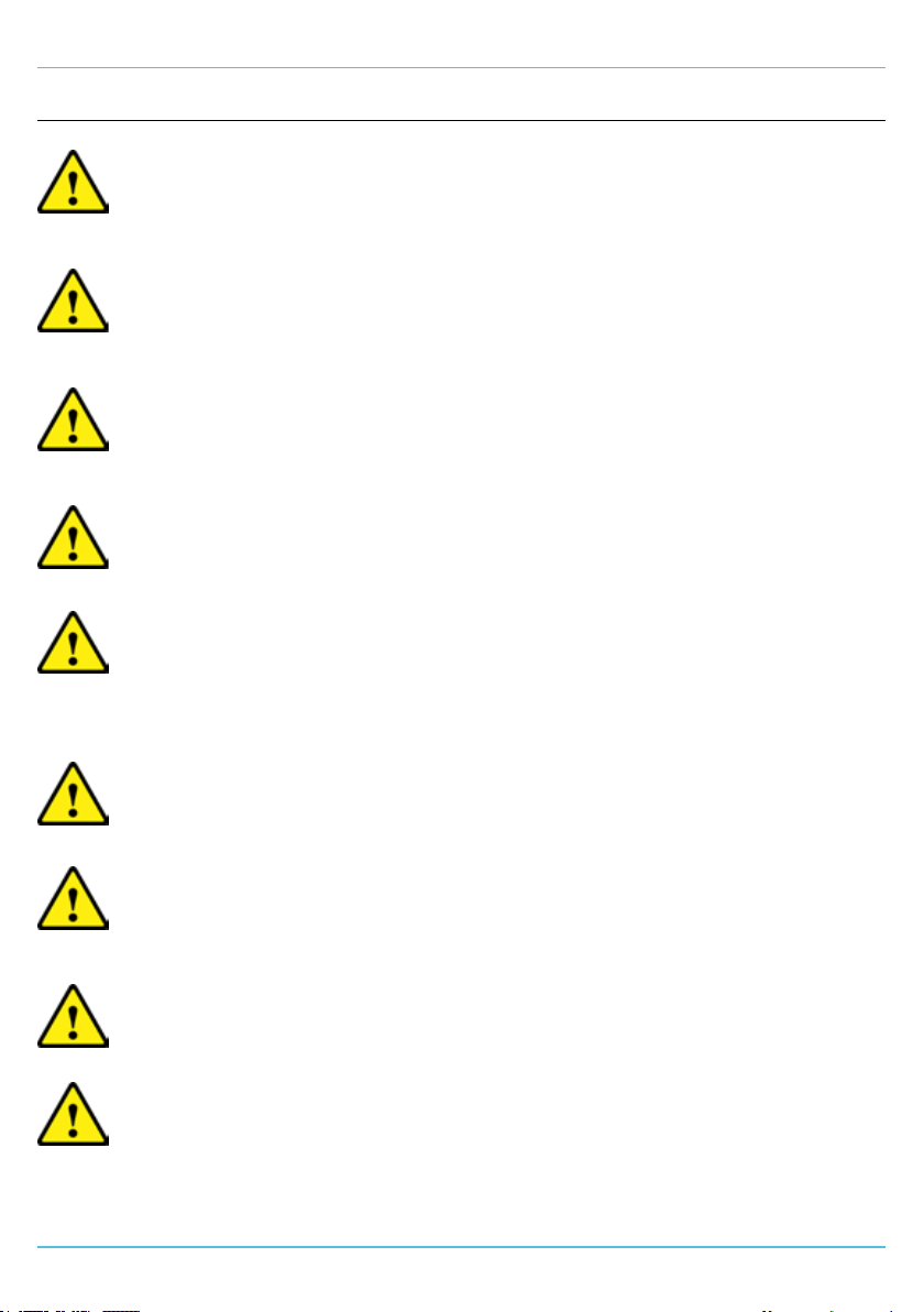
Warning:
Do not store explosive substances such as aerosol cans with a
ammable propellant in this appliance.
Warning:
Do not use electrical appliances inside the storage compartments of this
appliance.
Warning:
Keep ventilation openings of the appliance enclosure or the structure of
built in equipment, clear of obstruction.
Warning:
Do not use mechanical devices or other means to accelerate the
defrosting process.
Warning:
Do not damage the refrigerant circuit, i.e. pipe work or components.
ELECTRICAL
The appliance must be disconnected from its power source during
cleaning; when maintenance and the replacement of parts is required,
the equipment must be safely disconnected and isolated from the
power supply using a lock-o system at the isolation device.
IMPORTANT SAFETY INFORMATION
IMPORTANT SAFETY INFORMATION
It is advised that the electrical supply to the equipment is protected by
an appropriately selected Residual Current Device (RCD) with a rating no
greater than 30mA. RCD’s should be tested at least every three months
to ensure they are functioning correctly.
If the supply cord is damaged, it must be replaced by a service engineer
or other qualied person. Only the supply cord supplied by Williams
Refrigeration must be used.
Fixed wiring appliances (those not supplied with a plug) shall incorporate
a switch disconnector to meet the specication of IEC 60947; this is to
be installed within the xed wiring installation in accordance to the local
wiring rules / regulation to provide all pole disconnection of the power
supply.
3
Page 4
IMPORTANT SAFETY INFORMATION
IMPORTANT SAFETY INFORMATION
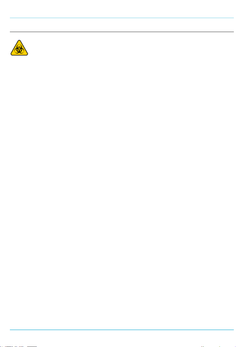
Warning! Damage to health due to infectious liquids and
pathogenic germs.
• When handling infectious liquids and pathogenic germs, observe
the national regulations, the biosafety level of your laboratory, the
material safety data sheets, and the manufacturer’s application
notes.
• Wear your personal protective equipment.
• For comprehensive regulations about handling germs or biological
material of risk group II or higher, please refer to the “Laboratory
Biosafety Manual” (source: World Health Organisation, Laboratory
Biosafety Manual, the current edition).
INFORMATION ON PRODUCT LIABILITY
In the following cases, the designated protection of the device may be aected.
Liability for any resulting damage or personal injury is then transferred to the
owner:
• The device is not used in accordance with the operating manual.
• The device is used outisde of its intended use.
• The device is used with accessories or consumables that are not
recommended by Williams Refrigeration.
• The device is maintained or repaired by persons not authorised by Williams
Refrigeration.
• The user makes unauthorised changes to the device.
4
Page 5
REMOVAL OF REDUNDANT APPLIANCES
If the product needs to be disposed of, the relevant
legal regulations must be observed.
Within the European Community, the disposal of
electrical devices is regulated by national regulations
based on EU Directives pertaining to waste electrical
and electronic equipment (WEEE).
According to these regulations, any devices supplied
after August 13, 2005, in the business-to-business
sphere, to which this product is assigned, many no
longer be displosed of in municipal or domestic
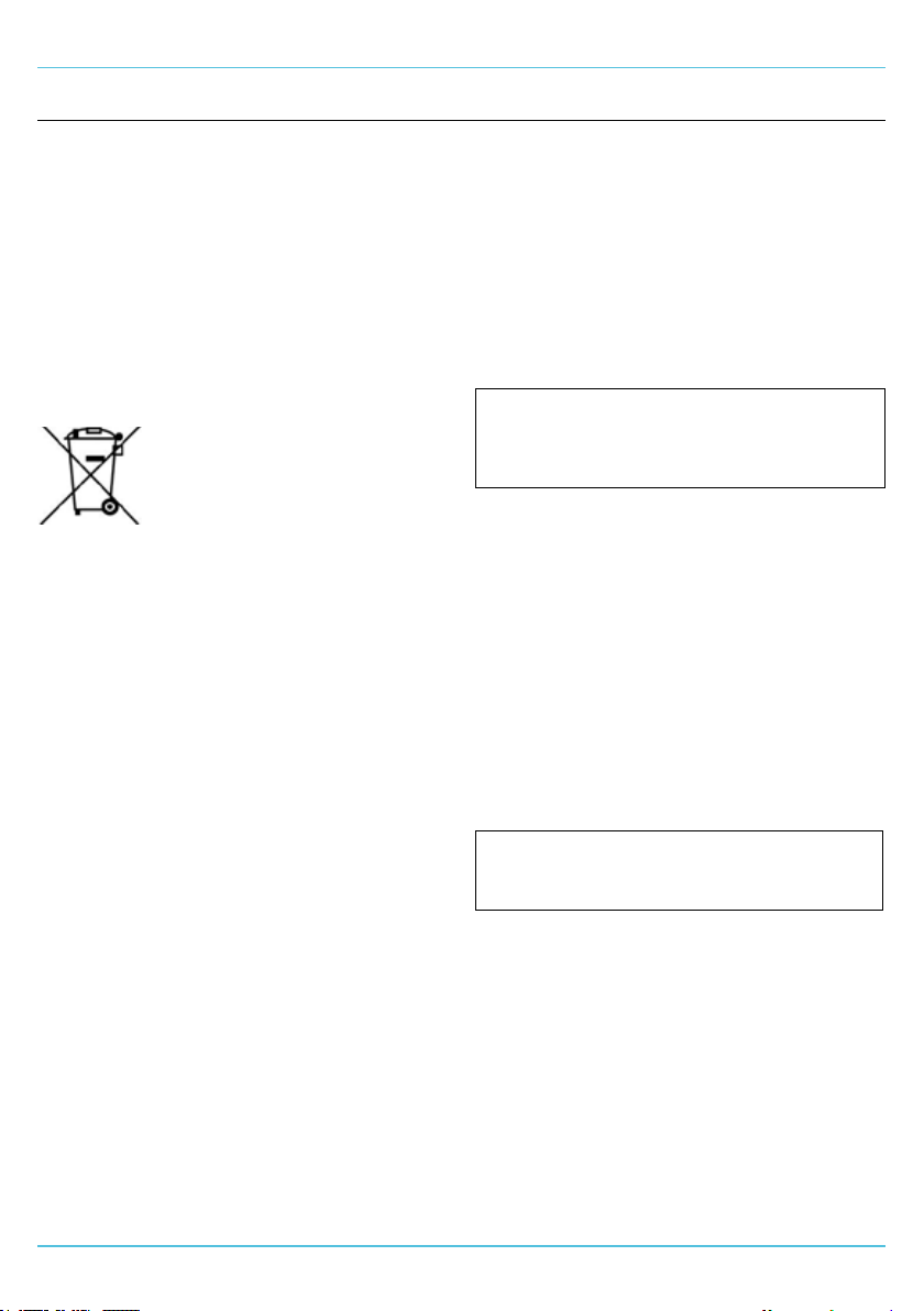
waste. To document this, they have been marked
with the following marking:
Do not dispose of batteries together with domestic
waste. Dispose of batteries in accordance with local,
legal regulations.
Refrigeration appliances contain refrigerant and
gases in their insulation and must be disposed of
professionally by a licensed waste management
contractor.
Please ensure that old or redundant refrigeration
appliances are disposed of safely and legally. It is
recommended that doors are removed prior to
disposal in order to ensure safety.
Because disposal regulations may dier from one
country to another within the EU, please contact
your supplier if necessary.
UNPACKING
Remove all external and interior packing and
accessories. Ensure all such material is disposed
of safely.
Check that no damage has occurred to the
appliance, the tubing of the refrigeration system
power cable and plug top during transit. If damage
has occurred do not use the appliance.
The appliance should be installed in a well ventilated
room on a at and level oor.
PROTECTIVE COATING
The polished stainless steel surfaces are protected
during manufacturing and transport by an adhesive
plastic coating.
INSTALLATION
INSTALLATION
This should be removed prior to placing your
appliance into use. Carefully peel away to reveal
the polished stainless steel surface. Care should be
taken to ensure that no adhesive residue remains
on the surface. Any stubborn or tough adhesive
marks can be removed by following the advice on
Page 10.
INSTALLATION
During the initial start up, high temperature alarm
may sound while the appliance reaaches operating
temperatures. Allow the appliance to stabilise at the
set point before storing product.
If the appliance has been laid on its back
or tipped, DO NOT switch on immediately.
Leave in an upright position for at least 3
hours before switching on.
VENTILATION
Refrigerators generate a considerable amount of
heat and, if operated in a small unventilated room
will quickly cause the room temperature to become
excessive. This could cause the motor to overheat
and possibly damage the compressor. At the very
least, such an installation will cause the unit to use
an excessive amount of electricity.
In addition to ventilation in a room, please ensure
that cabinets with top-mounted systems have
500mm clearance between the cabinet top and the
ceiling for engineer access and ventilation. For all
other cabinets, please ensure a minimum clearance
of 50mm is provided around the unit to ensure
ecient and eective performance.
Do not block vents by stacking boxes on top
or in front of the unit as this could aect
performance and give rise to safety risk.
LEVELLING (CASTORS/FEET)
The appliance should stand level to ensure the
correct operation of self-closing doors and proper
drainage of condensate from the evaporator.
Models tted with castors are non-adjustable.
Therefore a level platform / oor should be
provided where the appliance is to be located.
Where swivel and brake castors are tted and it
has been positioned, please ensure its brakes have
been activated by pressing the metal bar down.
Remember to release the brakes before trying to
move it.
On models tted with levelling feet, levelling may be
achieved by adjusting them rst.
5
Page 6
INSTALLATION
MAINS CONNECTION
Refrigeration equipment is commonly used
in environments located close to liquids,
and is usually operated in and around damp
conditions, or where restricted movement for
installation and service is evident.
Great care must be exercised at all times
when installing, operating, or servicing this
appliance.
The equipment is to be powered by a suitable
socket outlet which provides means of switching
o and/or disconnecting the power supply to the
equipment for cleaning or maintenance purposes. It
should be positioned in a clearly visible location, and
be easily accessible at all times. It is advised that
a label be xed adjacent to the designated socket
outlet for identication purposes, stating the outlet
is used to power the specic medical refrigeration
equipment.
For appliances tted with a moulded plug for safety,
ensure that the mains power cable is extended
free from the refrigeration system to avoid
entanglement. If a plug or mains cable requires
replacement, contact the Williams Spares Oce on
+44(0)1553 817017.
The installation of a xed appliance and periodic
inspection should only be undertaken by a qualied,
skilled, and competent electrician; and connected
to the correct power supply suitable for the load as
stipulated by the appliance data label.
The electrical installation and connections should
meet the necessary requirements to the local
electrical wiring regulations and any electrical safety
guidelines.
All appliances rely upon a suitable connection to
earth to ensure safe operation. If in doubt, contact
a qualied, skilled, and competent electrician before
using the appliance.
We recommend:-
• Supplementary electrical protection with the
use of a residual current device (RCD)
• Fixed wiring appliances incorporate a locally
situated switch disconnector to connect
to, which is easily accessible for switching
o and safe isolation purposes. The switch
disconnector must meet the specication
requirements of IEC 60947
If the appliance has been laid on its back
or tipped, DO NOT switch on immediately.
Leave in an upright position for at least 3
hours before switching on.
Your attention is drawn to:-BS 7671:2018 Guidance note 8 - 8.13 : Other locations of
increased risk
It is recognised that there may be locations of
increased risk of electric shock other than those
specically addressed in Part 7 of BS 7671.
Examples of such locations could include laundries
where there are washing and drying machines
in close proximity and water is present, and
commercial kitchens with stainless steel units, where
once again, water is present.
Where because of the perception of additional risks
being likely, the installation designer decides that an
installation or location warrants further protective
measures, the options available include:
• Automatic Disconnection of Supply (ADS) by
means of a residual current device having
a residual operating current not exceeding
30mA;
• Supplementary protective equipotential
bonding; and
• Reduction of maximum fault clearance time.
The provision of RCDs and supplementary bonding
must be specied by the host organisation’s
appointed installation designer or electrical
contractor and installed by a suitably qualied
and competent electrician so as to comply with
Regulations 419.2 and 544.2. RCD’s should be
tested at least every three months to ensure they
are functioning correctly.
SUPERVISORY & NETWORK CONNECTIVITY
(OPTIONAL)
There is an option to connect the Medi+
refrigeration equipment to third party supervisory
networks and systems such as Building
Management Systems (BMS), and IoT cloud based
systems via an RS485 Modbus data connection. This
will allow for a comprehensive supervision of the
equipment operating parameters and status, such
as internal temperature, defrost cycles and alarms.
The Medi+ equipment controller also provides a volt
free contact, which can be connected to a BMS to
monitor general alarm conditions.
NB: A proprietary cable from Williams
Refrigeration is required and, only suitably
qualied and competent engineers should
install this equipment to such systems. For
more information, please contact Williams
Refrigeration on +44(0)1553 817000.
6
Page 7
INSTALLATION
MAINS POWER SUPPLY FAILURE ALARM
(OPTIONAL)
This alarm is to help safeguard stored medical
samples/items by announcing when a failure of the
mains power supply has occurred. An audible (95dB
sounder), and a visual alarm (red ashing ‘Power
failure’ indicator) will activate in the advent of a
mains power supply failure.
The alarm will be continuous for a minimum of
12 hours, (whilst the mains power supply failure
remains), powered by a rechargeable battery
integrated into the alarm circuit; however, the
sounder can be muted at any time by pressing the
‘Mute’ button. Once muted, a blue ashing indicator
signies that the alarm has been muted. The red
ashing ‘Power failure’ indicator will continue to be
active whilst there is a failure of the mains power
supply.
When the mains power supply is reinstated the
‘Alarm muted’ function MUST be reset by pressing
the mute button once more, cancelling the blue
ashing indicator signifying that the alarm circuit is
ready to sense a power failure.
IMPORTANT: for the rechargeable battery
to receive a full charge, it is advised that
the mains power supply is connected for
at least 24 hours. As with all batteries, the
rechargeable battery has a nite operational
life which will vary dependent of a number of
factors, it is therefore, advised that the mains
power supply failure alarm is checked by a
service engineer as part of the routine periodic
servicing of the refrigerator. Only replace the
battery with a Williams Refrigeration approved
and supplied battery.
SHELF/SLIDE FITTING
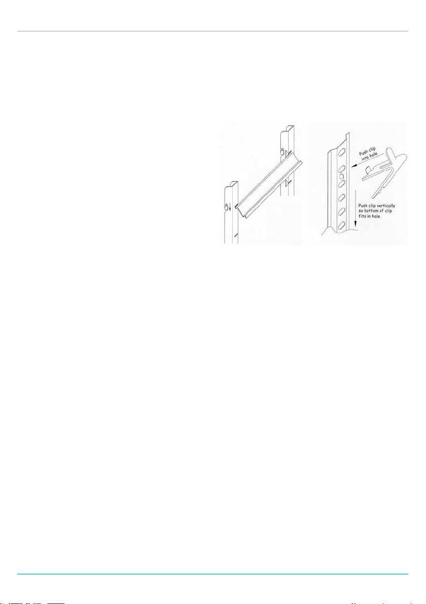
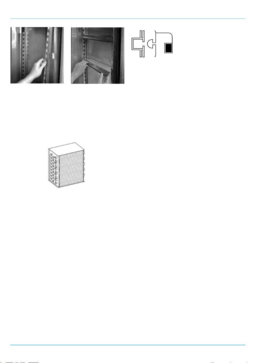
When positioning slides on standard cabinets and
counters, present slide to racking by holding it in
the opposite hand to the side of the cabinet to that
which they are to be applied. Present slide at 45°
angle (gure 1). When in place, let slide drop into
position to create a horizontal ledge on which the
shelves will sit.
FIG 1. FIG 2.
The WMP135 models are tted with pilaster and
clips (gure 2) for tting.
LOADING / SHELF DISTRIBUTION
Before loading, allow the appliance to reach its
normal operating temperature.
• Never load beyond capacity.
• Always store items within shelves.
• Uniform product temperature is maintained by
air circulation, ensure even loading.
• Do not place items against the rear plenum or
pushed against side walls.
When loading the appliance, please ensure that its
load is equally distributed throughout and ensure air
can circulate around and through stored products.
Care should be taken when loading the appliance.
Do not obstruct the air ducts. Take care of any parts
with possible sharp edges.
LOCKING FACILITY
On models with a locking facility, it is recommended
that the key be removed from its lock during normal
working use. This will prevent bending or breaking
of the key which could result in the lock having to be
replaced.
Removing the key will also prevent accidental
locking when the door is open. This will prevent the
door from closing properly and cause the interior
temperature to rise. If not checked in time, a loss of
product may result.
7
Page 8
CONTROLLER
CONTROLLER
CONTROLLER / DISPLAY
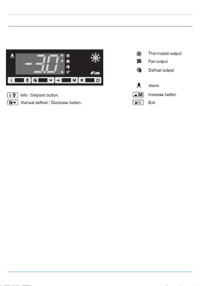
The display should be checked daily to ensure that
the correct temperature is being maintained.
Temperature set point
To adjust the cabinet temperature set point;
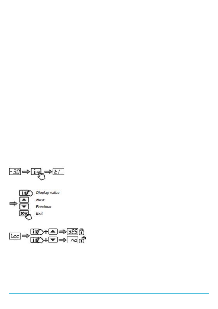
• Press the “i” button to display the set point
value.
• Keeping the “i” button pressed, use the “▲” and
“▼” buttons to adjust the value.
• Releasing the “i” buttons stores the new value.
Information menu
It is possible to display more temperature
information, such as maximum and minimum
temperatures by accessing the information menu.
This can be viewed by pressing the “i” button, and
releasing. Using the “▲” and “▼” buttons the
following information can be displayed;
• “t1”: Probe 1 (air) instantaneous temperature.
• “t2”: Probe 2 (evaporator) instantaneous
temperature.
• “th1”: Maximum probe 1 recorded temperature.
• “tL1”: Minimum probe 1 recorded temperature.
Whilst accessing the information menu, it is possible
to reset the “th1” or “tL1” recorded values as
follows;
• First select either “th1” or “tL1” to reset using
the “▲” and “▼” buttons.
• Display the value to reset by pressing the “i”
button.
• While keeping the “i” button pressed, press the
“x” button to reset the value.
To exit the information menu, either wait 10
seconds, or press the “x” button.
Alarms
An alarm is reported via the display through the
ashing of an abbreviation indicating its cause:
• “HI”: Cabinet high temperature alarm.
• “LO”: Cabinet low temperature alarm.
• “DO”: Door open alarm.
• “CL”: Condenser cleaning warning (if enabled).
• “E1”: Failure of probe T1 (Air).
• “E2”: Failure of probe T2 (Evaporator).
Internal Light
If the Medi+ refrigerator is tted with an optional
light(s), an independent light switch will be provided,
which will allow control over the internal light(s).
DEFROST OPERATION
The controller will instigate an automatic defrost
cycle. The refrigeration system is turned o whilst
the electric defrost system is switched on. This
defrosts the evaporator coil. The operation raises
the temperature of the Medi+ cabinet slightly for a
short period but does not aect the stored product.
When defrost is in progress, the defrost indicator on
the control panel will become illuminated and “dEF”
is displayed until the defrost cycle has nished.
A manual defrost can be activated by pressing and
holding the “▼” button on the controller for 2
seconds.
8
Page 9
HI-LO ALARM
The Medi+ controller features a built in audio/
visual Hi-Lo alarm. If the temperature within the
cabinet storage area exceeds the factory set alarm
temperature and duration, the control will display
a temperature alarm and activate a sounder. The
alarm can be cancelled by pressing the “i” button.
PROBE FAIL SAFE FEATURE
The Medi+ controller features a special fail-safe
condition. In the event of a temperature probe
failure the compressor will not continue in normal
sequence.
Instead the compressor will switch to a ve minute
cycle, which it cycles on for ve minutes then o
for ve minutes. The normal compressor cycle
will be restored upon the repair of the probe fault.
This feature is designed to avoid the compressor
overheating and protect the stored contents of the
equipment until manual intervention is possible.
LOCKING/UNLOCKING THE CONTROLLER
KEYPAD
It is possible to lock the electronic controller
interface keypad to prevent accidental changes to,
and general ampering or unauthorised changes
to, the controller operation including changes to
temperature set points.
To achieve this, follow the sequence below;
CONTROLLER
9
Page 10

APPLIANCE ROUTINE MAINTENANCE / CLEANING
APPLIANCE ROUTINE MAINTENANCE / CLEANING
ROUTINE MAINTENANCE
Regular servicing of the appliance should be
undertaken to ensure correct operation, it is
functioning as intended and safe to use.
Safely disconnect the appliance from the power
suppy before cleaning, servicing or undertaking
general maintenance.
This appliance must be maintained at regular
intervals. The frequency of maintenance will depend
upon your specic use and location. The maximum
service interval should be 12 months.
Service and maintenance should only be undertaken
by suitably qualied, trained and competent
engineers.
We recommend servicing in accordance with SFG20
Maintenance Schedules and as a minimum, after
4,500 hours of use, or annually, whichever comes
rst and that a maintenance contract be arranged
with an appointed service contractor. Visits may
then be made at agreed intervals to carry out
required safety tests, functional checks, adjustments
and repairs.
CLEANING
Always wear appropriate personal protective
equipment (PPE) when cleaning the appliance. Care
should be taken for parts with possible sharp edges.
Stainless steel is naturally corrosion-proof and
needs no additional protective coating to maintain
its gloss and usability for a long time.
Abrasive or corrosive cleaning agents should never
be used. These can damage surfaces and cause
corrosion. They include:
• Cleaners containing chloride;
• Bleaches containing hypochlorite (if accidentally
spilled on stainless steel, rinse o with water
immediately and thoroughly);
• Silver polish
If the cabinet exterior is looked after correctly it will
retain an “as new” nish for many years. A damp
cloth is usually sucient for wiping away light dirt
and nger marks and normal day to day cleaning
should be carried out with a soft cloth and soapy
water.
Dry thoroughly afterwards and where possible
remove all racking and shelving ttings to aid the
process.
For stainless steel with visible polishing grains, clean
the steel with the grain - not against the grain. When
water has been used for cleaning or rinsing, wipe
the surface dry to prevent water from drying and
forming watermarks, especially in areas with hard
water. Avoid this type of watermark by using distilled
water.
For tougher spots, creamy polishes like CIF original
cream can be eective. Light pressure should be
used when cleaning with the grain. The cleaning
process should be repeated in order to prevent any
dirt becoming lodged in the surface grain again.
CIF original cream cleaner can also be used
for wiping o water spots and can alleviate
discoloration. Remove this type of residue by rinsing
with clean, preferably distilled water and wipe away
any remaining streaks of polish or watermarks.
Tough grease or oil marks can also be removed
using denatured alcohol or acetone. There is no risk
of corroding stainless steel by using such solvents.
For ease of use limit the amount of solvent used.
Wash more than once using a pure solvent on a
clean soft rag until all traces of the greasy residue
are removed.
Specialist Stainless Steel Cleaners
Innosoft B570 is a special deep cleaner that is
suitable for the intensive cleaning of contaminated
stainless steel surfaces, and removes stains and
oxides in a single operation.
Innoclean B580 completely removes any residues
left after the use of Innosoft B570 and passivates
the surface which helps to prevent further
corrosion.
With regards to the above recommended cleaners,
always check that they will not have any detrimental
eect to the stored contents.
SHELF / SUPPORT/ RACKING REMOVAL
First remove the shelves, then remove the shelf
supports by grasping rmly in the centre and lifting
slightly. Turn the shelf support towards the interior
of the cabinet by pushing it in the centre as you
twist the support through 90°. The shelf support
will be released. (NB: the supports are designed
to be anti-tilt and you may therefore experience
some resistance at rst which will be overcome with
practice). When all shelves have been removed,
remove the racking by lifting up and over the nylon
retaining blocks.
10
Page 11
APPLIANCE ROUTINE MAINTENANCE / CLEANING
CONDENSER CLEANING
Regular maintenance should be carried out on a
regular basis by competent / trained personnel. The
condenser is part of the refrigeration unit and is
located in the unit compartment.
Brush ns vertically with a sti brush, taking care
not to damage them or to push dirt / dust further in,
and then vacuum away.
FIG 3.
Damaged gaskets are easily
replaced. Simply pull out the
existing part and push the new
gasket into the channel (gasket
retainer) at the centre and work
along, pushing gasket into
channel.
EVAPORATOR/DRAINLINE
Inspect periodically to ensure the drain hole is not
blocked.
BREAKDOWN
You must immediately report any damage or defect
arising with the appliance. Unsafe equipment is
dangerous. Do not use the appliance. Isolate the
power supply and contact Williams Refrigeration or
your appointed Service Provider.
In the event of a breakdown, please contact Williams
Refrigeration or your Service Provider
When calling, please advise model and serial
number. This information can be found on the data
plate inside the appliance. Please ensure that all
redundant parts are disposed of safely and legally.
TOP MOUNTED CABINETS
(WMP620 - WMP1295)
The condensing unit and refrigeration equipment
can be accessed from above or in some cases
behind. Remove xings in the top and bottom edges
of the unit cover and pull the unit cover away from
the cabinet and retaining clips.
BOTTOM MOUNTED UNITS
(WMP523)
Pull the unit cover away from the cabinet and
retaining clips.
CLEANING / REPLACING THE GASKET
Door gaskets should be checked and cleaned
regularly and replaced if damaged. To clean the
gasket, wipe with warm soapy water and a soft cloth,
ensuring it is completely dry before closing the door.
DO NOT use a sharp knife to clean or scrape the
gasket. Damaged gaskets do not seal correctly and
can increase the amount of electricity consumed,
seriously aecting the eciency and performance of
the appliance.
11
Page 12
TROUBLE SHOOTING / ALARM CODES
TROUBLE SHOOTING INFORMATION AND ALARM CODES
Fault Display Possible Cause Action
Cabinet not operating No power supply Check fuse or power source
Cabinet not maintaining
temperature
Faults displayed by control E1 or E2 - Control probe failure Call engineer
TROUBLE SHOOTING INFORMATION FOR THE MAINS POWER SUPPLY FAILURE ALARM
(OPTIONAL)
Fault Possible Cause Action
The sounder is not working
when mains power supply is
turned o
The red ‘Power failure’
indicator is not illuminating
when mains power supply is
turned o but the sounder
activates
The sounder and red indicator
not working when the mains
power supply is turned o
The sounder and red indicator
only work for a short period
when the mains power supply
is turned o
1. Dirty condenser Clean
2. Air circulation restricted Remove restriction
3. Defective fan motor Call engineer
4. Defector compressor relay Call engineer
5. Loose electrical connection Call engineer
HI or LO - High/low temperature
alarm*
DO - Door open alarm
CL - Condenser requires cleaning
Mute switch activated Check mute switch
Indicator not working Call engineer
Battery or alarm circuit faulty Call engineer
Battery requires full charge or
requires replacement
Call engineer
Shut door
Remove cover and clean condenser
ns with a clean brush
Call engineer if a full charge does
not resolve the issue
12
Page 13
SPARE PARTS
CHOOSING GENUINE SPARE PARTS
Choosing the correct spare parts is vital to the ongoing running of your appliance - that’s why Williams
Refrigeration oer a comprehensive network of servicing, support and spare parts all available directly from
Williams.
Our spare parts are exactly the same quality and standard as we use to build your appliance and have been
rigorously checked, tested and inspected to ensure the very best quality and exact t.
You can contact us directly for everything from fault diagnosis to parts selection and ordering. Simply provide
the serial number of your appliance and we will do the rest to ensure you receive the right part rst time.
For further information please call our Spares Department on 01553 817017
or email [email protected]
13
Page 14

WARRANTY
PARTS & LABOUR WARRANTY POLICY - UK ONLY
Our warranty applies to equipment manufactured
by Williams Refrigeration and equipment bearing the
Williams name plate and serial number identication
tag.
We undertake, in conjunction with the supplying
agent, distributor or representative, to repair free
of charge during our standard business hours
any such piece of equipment or part thereof used
which is found to be faulty in either materials or
workmanship subject to the further conditions
below:-
WARRANTY TERMS AND PRODUCTS
COVERED
We oer a 24 months Warranty from our original
date of sale with the following Williams equipment:
1. Williams Medi+ Range - WMP
WARRANTY TERMS
Our warranty is oered where the equipment has
been installed correctly and has not been subject to
misuse or abuse and is functioning correctly.
The equipment was purchased by the authorised
supplying distributor direct from Williams
Refrigeration and not through a wholesaler or other
supplier whose warranty terms may be dierent.
The Warranty Policy shall be non-transferable.
Replacement of defective equipment can only be
made with the approval of Williams Refrigeration.
Any repair under warranty will only be carried out
with the product in its position of operation or in a
suitable location on the customer’s premises. If the
product has to be removed for security or any other
reason, this will be subject to additional charge (may
include hydrocarbon charged equipment).
Warranty work will be covered by Williams
Refrigeration or by one of its appointed service
agents between the hours of 8.00am and 5.00pm
Monday to Friday. Any works undertaken outside of
these hours are chargeable.
RESPONSE TIME
We aim to respond to all warranty calls within 3
working days and will endeavour to respond next
working day where practical.
CLAIMS PROCEDURE
If a customer wishes to make a claim under the
terms of this warranty, the following procedure
should be observed:
1. Contact the supplying agent, representative or
distributor.
2. Quote the equipment model, serial number and
date of installation. The serial number is located
on the product identication plate inside the
cabinet, modular product door frame or similar
location. It is recommended that operators
should also record the serial number on the
operating instruction booklet supplied with the
product.
3. Contents risk and insurance responsibility
remains at all times with the customer.
EXCEPTIONS TO STANDARD WARRANTIES
1. The Standard warranty applies to equipment
located in Mainland GB only and excludes
locations subject to restricted or secure
access,oshore and marine applications.
Additional time and travel charges may be
applied to the following locations – Isle of Wight,
Channel Islands, Isle of Man, Northern Ireland
and Scottish Isles.
2. Any fault that is not reported within 10 working
days of being discovered.
3. Service calls to equipment under warranty,
or service calls made under chargeable
arrangements will be carried out in accordance
with standard conditions of sale. Unless
otherwise specied, a maximum of 15 minutes
of administrative time, not spent directly carrying
out servicing work, is provided for within the
supply. Any requirement for sta attending
the call to spend greater time than 15 minutes
due to administrative requirements, such as on
waiting time or security clearance, or health and
safety risk assessments, will be chargeable at
our prevailing rate. We reserve the right to apply
Time Travel & Call out charges if no fault is found
with the product or access is either restricted or
denied to our attending engineer.
4. No claim shall exceed the original selling price.
5. Claims for contents stored in the equipment
supplied (including pharmaceutical or other
items) and any consequential loss how so ever
arising are excluded under our warranty terms.
14
Page 15

WARRANTY
6. Components including gaskets, doors, drawers,
handles, shelves, tray slides, all internal xings,
plug and lead, connectors, the outer shell,
castors / legs, temperature probes, refrigerant
and blockages as well as consumable items such
as (but not limited to) batteries, fuses, light bulbs,
printer cartridges, keys, glass and paper roll.
7. Equipment manufactured to the customers’ own
design, Williams Refrigeration will not be liable
for any defect, non performance or improper
operation of the equipment arising from any
drawing design or specication supplied by the
customer, their representative or agent.
8. Second hand equipment.
9. The customer uses or installs the equipment in
such a way that it exceeds its design envelope or
operates the equipment at control parameters
other than those provided as standard factory
settings.
10. The customer fails to observe commonly
accepted operating practices.
11. The customer has not properly cleaned or
maintained the equipment or carried out
necessary servicing, including cleaning of the
condenser, in accordance with instructions,
literature or directions issued by Williams
Refrigeration. (Operating Instructions are
supplied with all equipment but also available at
www.williams-refrigeration.co.uk).
12. Equipment fails through improper installation by
others, misuse, abuse, accidental damage, power
loss or uctuations, re, ooding or acts of god.
13. Any third party item(s) connected to the
equipment that may aect performance.
14. The customer permits persons other than
those authorised by Williams Refrigeration to
perform or aect repairs or adjustments to the
equipment.
15. If authorised representatives of Williams
Refrigeration are denied full and free rights of
access to the equipment for inspection during
normal business hours as previously stated.
16. If Repairs are made using spare parts
or replacement items not supplied or
preauthorised by Williams Refrigeration.
17. The initial equipment supply date shall apply for
warranty validity for the subsequent supply of
replacement of parts or products.
EXTENDED WARRANTY
Extended Warranty oers the opportunity to protect
your equipment (subject to conditions outlined) for
an additional period of up to 5 years inclusive of
original warranty periods.
Should you require Extended Warranty, state on
your order or notify the Dealer or Williams Sales
Manager at the time of purchase and they will be
able to arrange it for you.
To ensure your Extended Warranty Policy remains
valid, at least one maintenance / service visit per
year must take place in years 2, 3, 4 and 5.
For further information or clarication please
call 01553 817000 or email to
[email protected] or write to
Williams Refrigeration, Bryggen Road, King’s
Lynn, Norfolk, PE30 2HZ
15
Page 16
Design Excellence : Cool Technology
Williams Refrigeration
Bryggen Road
North Lynn Industrial Estate
King’s Lynn
Norfolk PE30 2HZ
Sales Tel: +44 1553 817000
Sales Fax: +44 1553 817111
Spares Tel: +44 1553 817017
Spares Fax: +44 1553 817020
[email protected]
www.williams-refrigeration.co.uk
Williams Refrigeration Australia
38-42 Gaine Road
Dandenong South, Victoria 3175
Australia
Tel: +61 3 8787 4747
Fax: +61 3 8787 4787
[email protected]
www.williams-refrigeration.com.au
Williams Silver Frost
2 rue Conventionnel Huguet
23000 GUERET
France
Tel: +33 5 55 52 27 88
Fax: +33 5 55 62 10 61
[email protected]
www.williams-refrigeration.fr
Williams Refrigeration Hong Kong
Unit C, 12/F., Roxy Industrial
Centre,
58 - 66 Tai Lin Pai Road, Kwai
Chung,
New Territories, Hong Kong
Tel: +852 2407 5422
Fax: +852 2407 3767
[email protected]
www.williams-refrigeration.com.hk
Williams Dubai
P.O. Box 333215
607 Building 1B
Dubai Design District
Dubai
United Arab Emirates
Tel: +971 4 510 8203
www.williams-refrigeration.com
Williams Refrigeration is a trading name of AFE Group Limited.
Registered in England & Wales under Registered Number
3872673. Registered Office Address - Bryggen Road,
North Lynn Industrial Estate, King’s Lynn, Norfolk, PE30 2HZ
0699_OP_MEDI+ Medi+ O&M (E) | Rev 5 | November 2023
16
 Loading...