

Page 1

16P-3000-103
This booklet provides operation, auditing, adjustment, and diagnostics for DEFENDER.
POWER TURN ON
With power first applied, a sound is produced, general illumination comes on, and
random patterns appear on the CRT as the game sequences through RAM, ROM, and
battery checks. The game then comes up in game over. Messages are displayed for RAM
or ROM failures; refer to Power Up and Reset RAM/ROM Tests. If the game comes up in
Bookkeeping, turn the game OFF and back ON.
a. If the game now sequences through the tests and then comes up in game over,
the bookkeeping totals have been reset to zero.
b. If the game still comes up in bookkeeping, open coin door and turn the game
OFF and ON. The game will now sequence through the tests and come up in
bookkeeping. This is an indication of battery failure and the game has reverted to
factory settings. To return to game over:
1. Set switch to MANUAL-DOWN.
2. Depress ADVANCE to display Function 28.
3. Set switch to AUTO-UP and depress ADVANCE.
GAME OPERATION
GAME START - Insert coins - credits are displayed on CRT. Press 1 or 2-player
start.
PLAYER CONTROLS
UP-DOWN Switch – maneuvers player ship.
REVERSE Switch - reverses player ship direction.
THRUST Switch - controls player ship speed.
FIRE Switch - activates laser gun.
HYPERSPACE Switch - warps rocket to another quadrant, danger of possible
annihilation.
SMART BOMB Switch - destroys all alien ships on screen. A maximum of 3* per play.
GAME PLAY
Destroy alien ships and missiles. Rescue humanoids, pick them up, and return to
surface. Destroy all enemy ships for humanoid bonus and additional alien waves.
Bonus ships and Smart Bombs provided every 10,000* points.
HIGH SCORE SIGNATURE
Use UP/DOWN to select letters and FIRE button to lock in letter.
* Indicates adjustable features.
Page 2

BOOKKEEPING AND EVALUATION TOTALS (Functions 1-7)
Function
1. In game over mode, set switch to AUTO-UP and depress ADVANCE. The CRT
indicates Function 1 and total left chute coins.
2. Records audit totals and depress ADVANCE for functions 1-7. To review a total
that has been advanced past, set switch to MANUAL-DOWN and depress ADVANCE.
Functions are displayed one at a time as follows:
1 0 (Total) COINS LEFT
2 0 (Total) COINS CENTRE
3 0 (Total) COINS RIGHT
4 0 TOTAL PAID (Games)
5 0 (Total Bonus) SHIPS WON
6 0 TOTAL (Play) TIME (Minutes)
7 0 TOTAL SHIPS (Played)
3. Operate ADVANCE to display Function 28, SPECIAL FUNCTION. From Function 28
you can return to game over or zero audit totals and return to game over.
4. With switch set to AUTO-UP, perform a. or b. as desired.
a. To return to game over depress ADVANCE.
b. To zero audit totals and return to game over, operate HIGH SCORE RESET to
indicate "35" on CRT for Function 28 and then depress ADVANCE.
GAME ADJUSTMENTS (Functions 8-21)
l. In game over mode set switch to AUTO-UP and depress ADVANCE. The CRT
indicates Function 1 and total left chute coins.
2. To raise Function number on CRT, operate ADVANCE pushbutton with switch set
to AUTO-UP. To lower Function number operate ADVANCE with it set to MANUAL-DOWN.
3. With desired Function indicated, raise adjustment value by operating HIGH
SCORE RESET with switch set to AUTO-UP; 1ower value by operating HIGH SCORE RESET
with it set to MANUAL-DOWN. Value left on CRT is new setting. For values, see below
and, for pricing, Table l.
4. Repeat steps 2 and 3 until all desired adjustments have been made.
5. Operate ADVANCE until 28 0 SPECIAL FUNCTION is indicated on CRT. From
Function 28 you can return to game over or restore factory setting. Perform step 6
or 7 as desired.
6. To return to game over, depress ADVANCE with switch set to AUTO-UP.
Function Tota1* Description
8 10,000 BONUS SHIP LEVEL(O=No Bonus ships)
9 3 SHIPS PER GAME
10 3 COINAGE SELECT
11 1 LEFT COIN MULT
12 4 CENTER COIN MULT
13 1 RIGHT COIN MULT
14 1 COINS FOR CREDIT
15 0 COINS FOR BONUS
16 0 MINIMUM COINS
17 0 FREE PLAY (Set to 1 for Free Play)
18 0 STARTING DIFFICULTY: O=LIB; 1=MOD; 2=CONS
19 10 PROGRESSIVE WAVE DIFFICULTY LIMIT> 4-25
20 1 BACKGROUND SOUND 0 =OFF 1 = ON
21 5 PLANET RESTORE WAVE NUMBER
22 0 NOT USED
23 0 NOT USED
24 0 NOT USED
25 0 NOT USED
26 0 NOT USED
27 0 NOT USED
28 0 SPECIAL FUNCTION
Tota1* Description
* Factory Settings
e.g. 5=LIB; 10=MOD; 15=CONS
* Factory Settings
Page 3
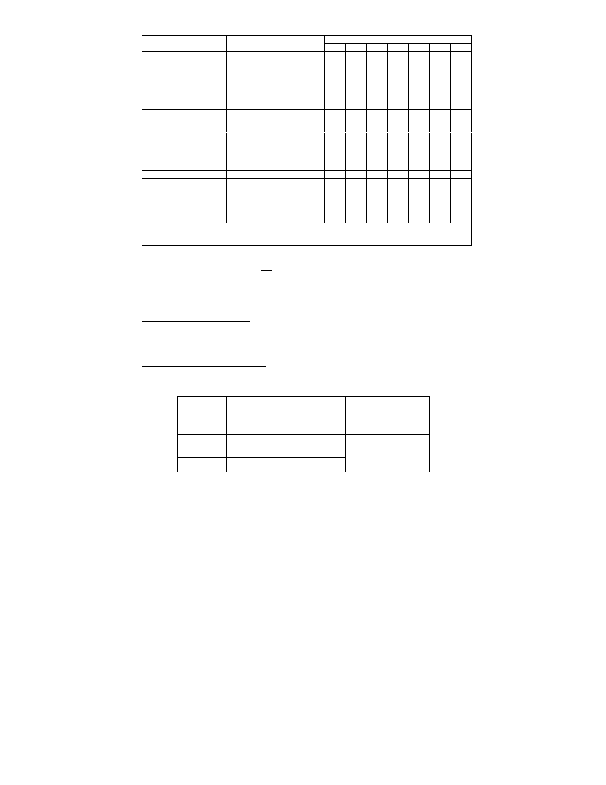
COIN DOOR MECHANISM CREDITS
All USA Variants ˜1/25¢, 5/$1
1DM, 5DM
20-Cent, 50-Cent
1 Franc, 5 Franc l1/2F, 3/5F only 04 01 16 06 02 00 00
25 Cent,
1 Guilder
5 Franc,
10 Franc
1 Franc, 2 Franc l2/1F 5/2F 02 00 04 01 04 00 00
100 Lire, 200 Lire ˜1/200 Lire 00 01 00 02 02 00 00
Twin Coin l1/1 Coin
1 Unit, 5 Unit l1/2, 3/5
l Indicates standard price settings by adjusting only Function 10. For other price
settings, set Function 10 to 00 and set. Functions 11 through 16 to the values
indicated in the chart.
˜2/50¢, 5/$1
l1/25¢, 4/$1
˜2/50¢, 4/$1
˜1/50¢, 3/$1, 4/$1.25
˜1/50¢, 3/$1, 7/$2
l1/50¢, 3/$1, 6/$2
l1/50¢
l1/1DM, 6/5DM
˜1/20¢, 3/50¢
l1/25¢, 4/1G
˜1/25¢, 5/1G
l1/5F, 2/10F
l1/10F
l1/2 Coins
˜1/3 Coins, 2 5 Coins
˜1/1, 5/5
˜1/3, 2/5
10 11 12 13 14 15 16
00
01
00
01
03
01
00
01
00
03
00
12
01
01
05
01
02000601000001010102000000
06000101000004040101000400
07080101000002020102000000
03
01
05
01
00
02
04
01
00
01
00
02
FUNCTION
04
04
04
04
12
48
04
04
04
04
00
00
00
00
01
01
01
01
01
03
12
01
01
01
01
02
06
05
10
04
01
04
01
00
01
00
04
15
14
96
02
04
02
00
01
00
02
00
05
00
02
00
01
00
05
00
Table 1. Standard and Custom Price Settings
7. To restore factory settings and zero audit totals:
a. Operate HIGH SCORE RESET in AUTO-UP to indicate "45" on CRT for Function 28.
b. Depress ADVANCE. The game returns to Audit Function l.
c. Set switch to MANUAL-DOWN and depress ADVANCE to indicate Function 28 on the CRT.
d. Set switch to AUTO-UP and depress ADVANCE.
RESETTING HIGH SCORE FEATURE
To reset the high score to the factory setting and erase signatures, depress
HIGH SCORE RESET in game over mode.
00
02
00
02
00
24
00
00
00
00
00
00
00
00
00
00
00
POWER-UP AND RESET RAM/ROM TESTS
Test initiated at power turn-on and after depressing RESET pushbutton on CPU/Video
Board.
RESULT
PASS
FAIL RAM
FAIL ROM
CRT
INDICATION
INITIAL
TESTS OK
RAM TEST
FAILED
ROM TEST
FAILED
LED
INDICATION
llll
4 LEDs blink
twice
l¡¡l
1st and 4
LED’s light
th
None
CORRECTIVE ACTION
None
Depress ADVANCE in
MANUAL-DOWN while
failure message is
displayed to enter
Diagnostics.
Page 4

ROM DIAGNOSTICS – TEST 1
Chip Indicated:
Indicated:
From game over, depress ADVANCE IN MANUAL-DOWN.
RESULT
PASS ALL ROMS OK
FAIL
RAM DIAGNOSTICS – TEST 2
From ROM Diagnostics depress ADVANCE in AUTO-UP.
RESULT
TESTING
PASS ALL RAMS OK
FAIL
CRT
INDICATION
ROM FAILURE
x
(x=ROM No
1 – 12)
CRT
INDICATION
Random
Pattern
RAM FAILURE
xy
(x=Bank,
y=Chip No)
LED INDICATION CORRECTIVE ACTION
l¡¡¡
1st LED blinks
twice.
l¡¡¡
1st LED lights.
¡¡¡l
¡¡l¡
¡¡ll
¡l¡¡
¡l¡l
¡ll¡
¡lll
l¡¡¡
l¡¡l
l¡l¡
l¡ll
ll¡¡
LED INDICATION CORRECTIVE ACTION
None
¡l¡¡
2nd LED blinks
twice.
¡l¡¡
2nd LED lights.
Bank Indicated:
l¡¡¡ = 1
¡l¡¡ = 2
¡¡l¡ = 3
Chip
¡¡¡l = 1
¡¡l¡ = 2
¡¡ll = 3
¡l¡¡ = 4
¡l¡l = 5
¡ll¡ = 6
¡lll = 7
l¡¡¡ = 8
None
Replace ICx on ROM Board
or depress ADVANCE in
MANUAL-DOWN; Replace:
IC1
IC2
IC3
IC4
IC5
IC6
IC7
IC8
IC9
IC10
IC11
IC12
Depress ADVANCE in AUTO
to bypass test.
None
Replace RAM (see
following) or depress
ADVANCE in MANUAL-DOWN
Depress ADVANCE in
MANUAL-DOWN
Replace in bank:
1 2 3
4L 5L 6L
4M 5M 6M
4N 5N 6N
4O 5O 6O
4P 5P 6P
4Q 5Q 6Q
4R 5R 6R
4S 5S 6S
Page 5

CMOS RAM DIAGNOSTICS – TEST 3
From RAM Diagnostics depress ADVANCE in AUTO-UP.
RESULT
PASS
FAIL
CRT
INDICATION
CMOS RAM
TEST PASSED
CMOS RAM
FAILURE
CMOS
INTERLOCK
FAILURE
LED INDICATION FAULTY AREA
¡¡l¡
3rd LED blinks
twice.
¡¡l¡
3rd LED lights.
¡¡l¡
3rd LED lights.
CMOS RAM 1I memory
protect gates 2H, 1K, or
address decoder 2F, 4E.
Coin door interlock,
Memory protect gates 1J,
2H, OR CMOS RAM 1I
None
COLOUR RAM TEST – TEST 4
From CMOS RAM test depress ADVANCE in AUTO-UP.
CRT SEQUENCES THROUGH 8
COLOURS, 2 SECONDS EACH
VERTICAL BAND INDICATES
COLOUR RAM FAULT.
¡¡¡l
4TH LED REMAINS LIT
DURING TEST
SEQUENCES
1 LIGHT RED
2 RED
3 DARK RED
4 LIGHT GREEN
5 GREEN
6 DARK GREEN
7 LIGHT BLUE
8 BLUE
9 DARK BLUE
4 LIGHT GREEN Band of green Band of dark green
RAM 1L RAM 1O
Band of red
intensity variance
or washout
Band of yellow Band of cyan
Band of magenta Band of blue
5 GREEN Band of light green Band of faint
6 DARK GREEN Band of washout
Note that a blank sequence or two sequences with same
shade indicate 1L or 10 RAM or color analogue circuit
faulty.
FAULTCOLOUR
Band of magenta
intensity variance
or washout
or washout
green, Band of
darker green
Tests 5 and 7 provide sequential subtests. To stop automatic cycling set
switch to MANUAL/DOWN. Depress ADVANCE in MANUAL-DOWN to step through
subtests.
SOUND TEST – TEST 5
From Color RAM test, depress ADVANCE in AUTO-UP.
Test sequences sounds 1 through 31, skipping 19, 27, and 28.
Missing Check
1 2P4/10P3 Pin 3
2 2P4/lOP3 Pin 2
4 2P4/10P3 Pin 5
8 2P4/10P3 Pin 4
16 2P4/10P3 Pin 7
All Perform Sound Board Diagnostics
Page 6

SWITCH TEST – TEST 6
2 - PLAYER START
CRT indicates AUTO-UP closed and any stuck switches. Set switch to MANUALDOWN and clear any stuck switches. CRT should indicate no switches closed.
Operate switches and check for display of switch name.
Coin Door Player Panel
ADVANCE UP
HIGH SCORE RESET DOWN
LEFT COIN REVERSE
CENTER COIN 1 - PLAYER START
RIGHT COIN
MONITOR SET UP TEST PATTERNS - TEST 7
From Switch Test depress ADVANCE in AUTO-UP.
Pattern Alignment/Adjustment
CROSS HATCH Vertical and Horizontal Linearity, Convergence, Focus
RED
GREEN
BLUE
COLOUR BARS
}
} Color Purity
}
HYPERSPACE
SMART BOMB
THRUST
FIRE
1 2 3 4 5 6 7 8
1 = RED
2 = GREEN
3 = BLUE
4 = WHITE
5 = BLACK
6 = YELLOW
7 = CYAN
8 = MAGENTA
The color bar pattern is also analyzed to detect color RAM faults. If Color RAM
Test 4 indicates no faults, a double-width band, half width bands, transposition or
missing bands indicates a fault in 2I, 1L, or 1O chips.
To return to game over:
l. Depress ADVANCE in AUTO-UP. Audit function 1 is displayed.
2. Set switch to MANUAL-DOWN and depress ADVANCE. Special Adjustment Function 28 is
displayed.
3. Set switch to AUTO-UP and depress ADVANCE.
INITIATING AUTO-CYCLE MODE
1. Set switch to AUTO-UP and depress ADVANCE. Audit Function 1 is indicated on CRT.
2. Set switch to MANUAL-DOWN and depress ADVANCE to indicate SPECIAL FUNCTION 28 on
CRT.
3. Set switch to AUTO-UP and operate HIGH SCORE RESET to indicate 15 on CRT for
Function 28.
4. Depress ADVANCE. The game sequences through ROM, RAM, Sound tests and monitor
test patterns.
5. To exit the AUTO-CYCLE mode, depress ADVANCE in AUTO-UP.
Page 7

SOUND BOARD DIAGNOSTICS
Depress DIAGNOSTIC pushbutton on the bottom of the Sound Board. A check is made of
the Sound ROM and sounds are produced if the check is good. If sounds are produced
but not produced in Audio Test 5 check for ROM board PIA outputs on Sound Board
inputs that is stuck low. If no sound is produced either the Sound ROM, input
power, or other Sound Board circuitry is faulty.
"Warning: This equipment generates, uses, and can
radiate radio frequency energy and if not installed
and used in accordance with the instructions manual,
may cause interference to radio communications. As
temporarily permitted by regulation it has not been
tested for compliance pursuant to Subpart J of Part 15
of FCC Rules, which are designed to provide reasonable
protection against such interference. Operation of
this equipment in a residential area is likely to
cause interference in which case the user at his own
expense will be required to take whatever measures may
be required to correct the interference."
 Loading...