

Page 1
Setup InStructIonS
Dipole Antenna
Model ANT 024
MAN 073I © 2008 Williams Sound
Page 2
DeScrIptIon
The ANT 024 is a 75
tion at 72-76 MHz. It is intended for use with Williams Sound
receivers and the T35 or T27 transmitter.
Ohm
, shortened dipole, designed for opera-
contaInS:
1 - Bracket with Mounted Antenna
20’ - RG59 Coax Feedline with “F” Connectors
6 - Self-tapping Screws (FSS 668 BK)
6 - 5/16” Nylon Cable Clamps (PLC 006)
SpecIfIcat IonS
Dimensions: 15” (38 cm) High, Collapsed; 37.4” (95
cm) Extended; 7” (18 cm) Distance
from Wall.
Weight: 9 oz. (225 g)
Frequency Range: 72-76 MHz
Nominal Impedance: 75
VSWR: 3:1 or Better
Power Handling Capability:
Warranty: 90 Days
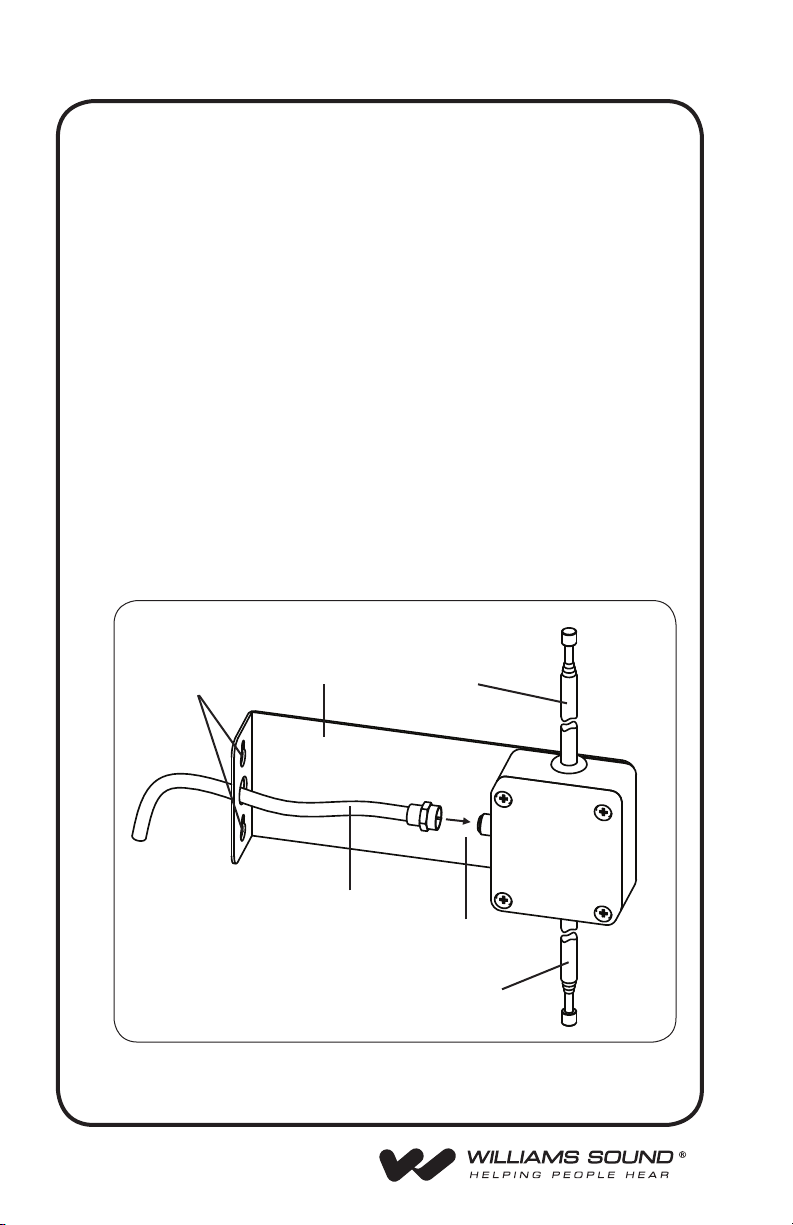
fIG. 1: ant 024 Setup
Ω
20 mW, Nominal
Mounting
Holes
Pass-Through
Hole (For Conduit
Installations)
Bracket Extendable
Coax Feedline
Antenna
Finger-tight
Connection
Extendable
Antenna
2
Page 3

Bracket-antenna InStallatIon proceDure:
Step 1: Select a mounting location for the Antenna Bracket.
It is best to locate the antenna high on a wall, within line-of-sight
of the area where the receivers will be used. Do not mount the
antenna behind steel beams or other metal structures. Radio
signals will generally pass through non-metal structures. The
antenna can be mounted on a wall, in a corner, or behind a
wooden beam. Antenna elements should be positioned vertically
for proper polarity and best coverage. If possible, avoid placing the antenna within four feet of steel beams or near structural
steel elements. Metal studs, duct work, and foil-backed insulation can absorb radio energy, greatly reducing the range of the
system.
Step 2: Use the antenna bracket as a template to mark the position of
the mounting holes.
Step 3: Attach the antenna bracket to the mounting surface. Use appro-
priate wall anchors (not included) if necessary. If you need to run
the feedline through a wall, a 1/2” hole is necessary to pass the
connector through.
coax feeDlIne caBle InStallatIon proceDure:
The Antenna Coax Feedline is a 20’ length of RG59 Coaxial
Cable. The feedline connects to the Antenna Connector on the
assembly as shown in the gure on page 2.
Step 1: Attach the Coax Feedline to the connector facing the wall. Use
ngers only to tighten. Arrange the Coax Feedline so that it exits
the antenna at a right angle.
Step 2: If this is not a conduit installation, use at least one of the nylon
cable clamps to support the weight of the cable.
Step 3: Attach the second cable clamp about 12” away from the rst
one, maintaining a right angle between the feedline and the
Antenna.
Step 4: Attach the other end of the Coax Feedline to the Antenna Con-
nector on the back of the transmitter. Use ngers only to tighten.
Step 5: Extend antenna elements out to their full length for maximum
range. Note: Antenna may be used in collapsed state, but range
will be reduced.
Notes: DO NOT bend the cable sharply at any point. Allow at least a 3”
radius for turns.
Up to 100’ of 75 Ω feedline can be added without excessive line
loss. Be sure to use the proper “F” connectors when adding
on to the feedline. The feedline can also be shortened and a
new “F” connector installed, if necessary. Do not coil up excess
cable.
The feedline is categorized as Class II wiring. Thus, it may be (but
is not required to be) routed through metal conduit, but NOT with
microphone cables or AC power wiring.
3
Page 4

recyclInG InStructIonS
Help Williams Sound protect the environment!
Please take the time to dispose of your equipment properly. Do NOT dispose of your Williams Sound equipment
in the household trash. Please take the equipment to a
electronics recycling center; OR return the product to the
factory for proper disposal.
MAN 073I © 2008 Williams Sound
 Loading...