

Page 1

1
Instructions for Williams Gas Appliance
Conversion Kits 8901, 8902 & 8903
Natural Gas to Propane Gas
KIT CONTENTS:
(1) Pressure Regulator (2) Conversion Labels
(4) Pilot Orifices (L.P. Gas) (2) Screws
(1) Burner Orifice (L.P. Gas) (1) L.P.G. Tag
Kit number 8901 & 8902 is for use with model numbers: 2509622; 3509622;
3509622.6; 3509922
Kit number 8903 is for use with model numbers: 5009622
WARNING: This conversion kit shall be installed by a qualified service agency in accordance with
the manufacturer’s instructions and all applicable codes and requirements of the authority having
jurisdiction. If the information in these instructions is not followed exactly, a fire, explosion or
production of carbon monoxide may result, causing property damage, personal injury or loss of life.
The qualified service agency is responsible for the proper installation of this kit. The installation is not
proper and complete until the operation of the converted appliance is checked as specified in the
manufacturer’s instructions supplied with the kit.
WARNING: The Williams conversion kit numbers 8901 & 8902 can only be used on the model gas
NUMBERS 2509622; 3509622; 3509622.6; 3509922, gas valve 6003. The Williams conversion kit
8903 can only be used on the model 5009622, gas valve 6003. They must never be used on any
other brand of gas valve. DO NOT USE THE CONVERSION KIT ON ROBERTSHAW BRAND GAS
VALVES. If you are unable to determine that gas valve model number, do not convert your furnace.
MANUFACTURED FOR USE WITH PROANE GAS AND EQUIPPED WITH GAS VALVE PART
NUMBER 6003 ONLY.
CAUTION: The gas supply shall be shutoff prior to disconnecting the electrical power (if equipped
with blower) before proceeding with the conversion.
CONVERSION INSTRUCTIONS-NATURAL GAS TO L.P. GAS
1. Shut off gas to the furnace.
2. Shutoff electric to the furnace (if equipped with blower).
3. Remove face panel from furnace.
4. Disconnect gas supply line from control valve.
5. Disconnect thermostat wires from control valve.
CAUTION: Label all wires prior to disconnection for proper reconnection
6. Remove manifold retaining plate from burner pan by unscrewing ( ) Phillips head screws.
Except model 35099(1, 2)2.
7. Remove burner pan from furnace by unscrewing ( ) Phillips head screws securing pan to
furnace. Except model 35099(1, 2)2.
8. Remove burners (item 2) by unscrewing ( ) Phillips head screws, screw on bracket (item 1)
and ( ) screw on burner (item 2). See figure 1
Note: Bracket (item 1) engages into slot on inner shield of furnace.
Page 2

2
9. Use a 7/16” boxed end wrench and remove the main burner orifices ( ) from the manifold and
replace with the orifices provided in this kit. See Figure 1.
10. Remove the pilot orifice from pilot and replace with orifice provided in this kit. See figure 2A,
B.
11. Replace the pressure regulator on the gas valve. Refer to Figure 3.
a. Push in the gas control knob slightly and turn clockwise to “OFF”
b. Remove (2) screws from the pressure regulator.
c. Lift the pressure regulator and gasket from valve and discard.
d. Install the new gasket, pressure regulator and (2) screws from this conversion kit.
IMPORTANT: Discard old gasket and screws. Do not reuse.
12. IMPORTANT: Check the location of the pilot to the burner. See Figure 4.
13. Reassemble the furnace by following Steps 1 thru 8 in reverse order.
IMPORTANT: LABEL PLACEMENT
After conversion is completed, the large conversion label provided in this kit must be filled out
completely (using chart information). Attach small conversion label to gas valve, and attach large
data conversion label to inside of the casing door next to rating plate. Remove:”Natural Gas” tag from
burner and replace with “Liquid Propane Gas’ tag provided with this kit. This is necessary to provide
information for future servicing. Failure to do so could result in property damage, personal injury or
death.
Refer to the Lighting and Operating Instruction Plate located in control area of furnace for instructions
on lighting the burner.
WARNING
Any adjustments must be performed by a qualified service technician only. Improper adjustments
could result in property damage, personal injury or death. The following information is provided for
use by a qualified service technician.
With main burner in operation, check all pipe connections, pilot gas tubing and around pressure
regulator for gas leaks with a rich soap and water solution. Bubbles indicate gas leakage. Never use
a match or open flame to test for leaks. Correct even the slightest leaks at once before using
furnace.
ADJUST PILOT BURNER
NOTE: Pilot gas may need adjustment depending on inlet pressure, increase or decrease to
obtain proper setting.
Pilot flame should surround 3/8 inch to 1/2 inch of the generator tip. To adjust, remove pilot
adjustment cap.
1. Remove screw cover over pilot adjusting screw.
2. Insert small screwdriver. Adjust flame as needed. Turn screw counter clockwise to increase
flame or clockwise to decrease flame.
3. Turn thermostat to highest setting. Main burner should light quickly and smoothly. Turn
thermostat to lowest setting. Main burner should go out. Pilot should remain lit.
4. Replace screw cover over pilot adjusting screw.
Page 3
3
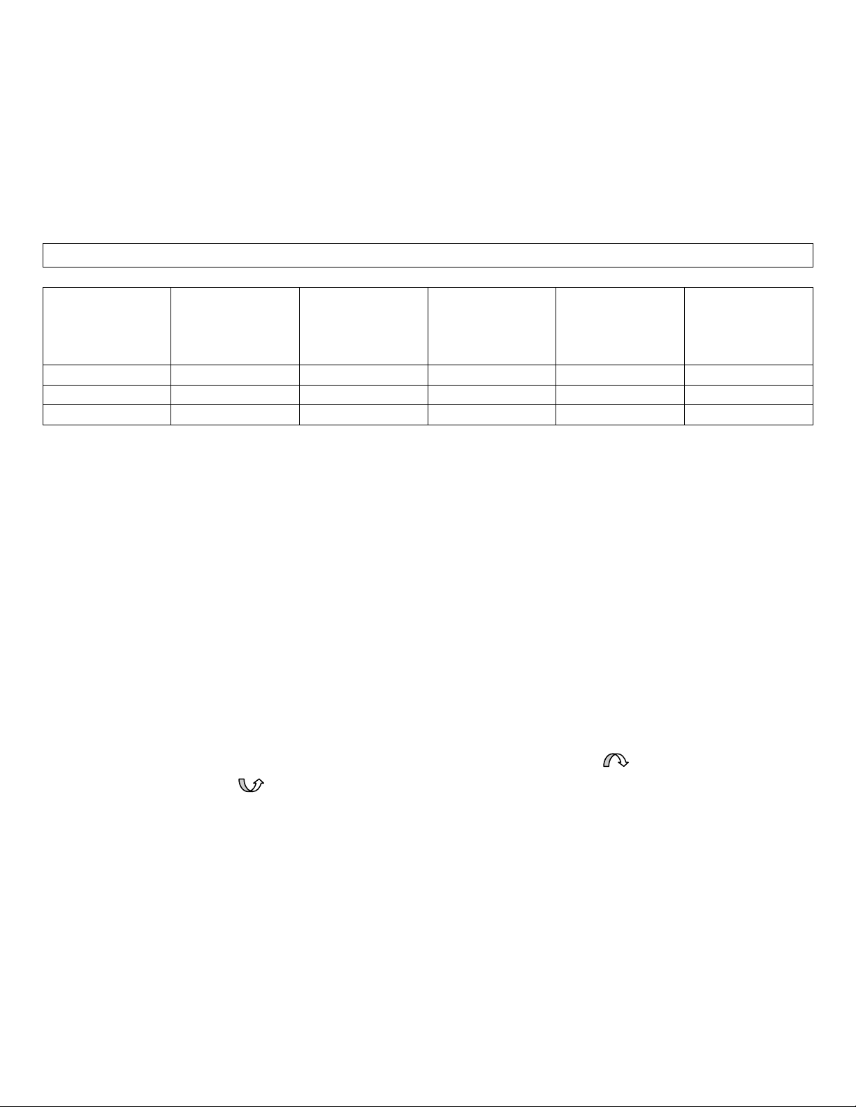
TO BE USED ON CONVERSION LABEL
KIT NO.
MODEL NO.
ON RATING
PLATE
NEW MODEL
NO.
NEW INPUT
BTU/HR
NEW
HEATING
CAPACITY
TU/HR
NEW ORIFICE
SIZE
8901
2509622
2509621
25,000
19,350
#54
8902
3509622
3509621
35,000
25,930
#52
3509622.0001
3509621.0001
32,000
25,930
#52
WARNING: DANGER OF PROPERTY DAMAGE, BODILY INJURY OR DEATH.
Liquid petroleum (L.P.) is heavier than air and it will settle in any low area, including open
depressions, and it will remain there unless area is ventilated. Never attempt startup pf unit
before thoroughly ventilating area. The surface of the furnace is hot during operation. Keep
children, clothing, furniture and flammable material away from it. Do not store or use gasoline
or other flammable liquids or vapors near the furnace.
CHART
After conversion is completed, the large conversion label provided in this kit must be filled out
completely (using chart information). Attach small conversion label to gas valve, and attach
large data conversion label to inside of casing door next to rating plate. Remove “Natural
Gas” tag from burner and replace with “Liquid Propane Gas” tag provided with this kit. This is
necessary to provide information for future servicing. Failure to do so could result in property
damage, personal injury or death.
CHECK GAS PRESSURE
The minimum inlet pressure in the in the gas supply should be 11.0” for Propane Gas. The
maximum inlet pressure should never exceed 13.0”. This should be checked at the 1/8” inch
N.P.T. plugged tapping in the supply line with a manometer.
The manifold pressure for this appliance is 10.3” w.c. for Propane Gas. Check with a
manometer at the pressure tap on the control valve. To adjust pressure, remove cap from
regulator and turn regulator adjustment screw on the control valve. To adjust pressure, remove
cap from regulator and turn regulator adjustment screw clockwise to increase and
counter clockwise to decrease pressure.
Page 4

4
RATE VERIFICATION
Refer to the lighting and Operating Instruction Plate located in control area of furnace for
instructions on lighting the pilot.
1. Make certain there is no gas flow through the meter other than to the appliance being
checked. Other appliances must remain off and the pilots extinguished (or their
consumption deducted from the meter reading).
2. With gas control knob in “ON” position, cycle main burner on and off several times by
means of thermostat o stabilize pressure regulator valve (PRV) diaphragm.
3. With second hand on watch, carefully clock gas meter to determine exact rate of gas
flow to main burner in cubic feet per hour (see CONVERSION TABLE below).
4. Compare actual input with manufacturer’s recommended hourly input stamped on rating
plate. Convert BTU per hour input rating to cubic feet of gas per hour (cfh) by using the
following formula.
Where as:
PRV = Pressure Input Rating in BTU per Hour = Cubic Feet of
Regulator Valve BTU Content of Gas per cu ft Gas per Hour
MJ= Megajoule Input Rating in MJ/hr = m3/hr
MJ of Gas per m3
M3= Metric Cube
5. If actual gas flow (cfh) does not conform to manufacturer’s recommended input rating
(cfh of BTU converted to CFH), a limited adjustment of the PRV may be made. Turn PRV
adjusting screw clockwise to increase or counter clockwise to decrease gas flow. Burner
input must not exceed nameplate rating.
6. Replace cap screw in PRV adjustment stack. Turn gas supply to other appliances back
on and re-light all pilots.
7. Place furnace in operation and observe through at least one complete cycle to be sure
all controls are operating satisfactorily.
Page 5

5
TIME
Sec
FLOW
Cfh
FLOW
M3/hr
TIME
Sec
FLOW
Cfh
FLOW
Cfh
TIME
Sec
FLOW
Cfh
FLOW
M3/hr
40
90
2.55
56
64
1.81
88
41
1.16
41
88
2.50
57
63
1.78
92
39
1.10
42
86
2.44
58
62
1.76
96
38
1.08
43
84
2.38
59
61
1.73
100
36
1.02
44
82
2.32
60
60
1.70
105
34
.96
45
80
2.27
62
58
1.64
110
33
.93
46
78
2.21
64
56
1.59
115
31
.88
47
77
2.18
66
54
1.53
120
30
.85
48
75
2.12
68
53
1.50
125
29
.82
49
73
2.07
70
51
1.44
130
28
.79
50
72
2.04
72
50
1.42
135
27
.76
51
71
2.01
74
49
1.39
140
26
.74
52
69
1.95
76
47
1.33
150
24
.68
53
68
1.93
78
46
1.30
160
23
.65
54
67
1.90
80
45
1.27
170
21
.59
55
65
1.84
84
43
1.22
180
20
.57
CONVERSION TABLE
For ½ cu. ft. per revolution of meter dial, multiply flow rate by 2.
For 2 cu. ft. per revolution of meter dial, divide flow rate by 2.
Page 6

6
IMPORTANT: LEAVE THESE INSTRUCTIONS WITH THE HOMEOWNER.
MANUFACTURED FOR: WILLIAMS FURNACE COMPANY, COLTON, CA USA (909)825-0993
6003 NATURAL 4”W.C. MAX ½ P.S.I. OR MILLIVOLT SYSTEM ONLY.
REPLACEMENT PART no. P323011 Made in Taiwan.
Page 7

7
 Loading...