

Page 1
.................................................................................................
=_ INSTRUCTIONS _OR WILLIAMS GAS APPLIANCE
CONVERSION KITS 7685, 7687, 7688, 7690 & 7691
iil=Jl_' i=,t;tl=_;,},]il'ii n_!l NATURAL G_S TO LIQUID PROPANE GAS
THIS KIT IS FOR USE
WITH MODEL NUMBERS:
This conversion kit shall be installed by a qualified
service agency in accordance
manufacturer's instructions and all
applicable
codes and requirements of the authority having
jurisdiction. If the information in these instructions
is not followed exactly, a fire, explosion or
production of carbon monoxide may result, causing
property damage, personal injury or loss of life.
The qualified service agency is responsible for the
proper installation of this kit, The installation is not
proper and complete until the operation of the
converted appliance is checked as specified in the
manufacturer's instructions supplied with the kit,.
3508332; 3508732; 5008732;
5508332; 6_08732; 6008532
PPL!CATION: THESE CONVERSION KITS ARE USED ON
E FORSAIRE TOP VENT WALL FURNACES WHEN
I_QUIPPED WiTH NATURAL GAS VALVES;
P323209 (STANDING PILOT MODELS)
i P3232t0 (ELECTRONIC IGNITION MODELS)
with the WITHhOmm STAINLESS STEEL BURNER 12956
dONVERTtNG TO L P GAS
THIS K_ CONTAINS:
(1} CAP SCREW
(t) PRESSURE REGULATOR ADJUSTMENT SCREW
(t) SPR_NG (RED)
(3) CONVERSION LABELS
(1 OR 2) PILOT ORIRCES (LP. GAS')
(1 OR 2) BURNER ORIRCES (LP GAS)
{1) LPG. TAG
{1) "O" RING
_AUTION:THE GAS SUPPLY MUST BE
SHUTOFF PRIOR TO DISCONNECTING THE
ELECTRICAL POWER BEFORE PROCEEDING
WITH THE CONVERSION,
I,,
2.,
3.,
4_
5_
,.
7,,
8_,
9,,
10o
11_
12.
13
I4.
!5
16,
17.,
18.
19,
2&
CONVERSION INSTRUCTIONS - NATURAL GAS TO LP. GAS
Shut off gas to the furnace,
Shut off electric power to the furnace,
Disconnect gas supply linefrom control valve
Remove electronic ignition module (ifequipped).
CAUTION: Label all wires prior to disconnection for'proper reconnection,
STANDING PILOT MQDELS ONLY_ Disconnect (2) tw$ wires from terminal block on thermocouple
and (2) two wires from control valve.
Use a 7/16" open end wrench to remove outer end nuts rom burner wire hangers and swing them up to
drop burner down. '_
NOTE: On single burner models, (2) two sheet metal ;crews are used instead of end nuts°
Pull the burner and control assembly forward to free itfrom he rear burner support bracket,
Once removed, all work can be performed on work bench.
Use a 7/16" boxed end wrench and remove the burner orifice(s) from the manifold and replace with the orifice(s)
provided in thiskit. Refer to Figure 1 on page 2
Remove pilot orifice from pilot and replace with orifice prov_ed in this kit, Refer to Figure 2A or B on page 2.
Remove regulator cap screw and pressure regulator adjust!ng screw Refer to Figure 3 on page 2.
Remove the existing spring, i
insertthe replacement red spring. Refer to Figure 4 on pa{e 2_
Install the new plastic pressure regulator adjustment screw !Assure that the screw top is flush with the regulator
top. I
Turn pressure regulator adjustment screw clockwise efever_complete turns. The preliminary pressure setting
isapproximately I0.,5 in, w.c. for LP gas regulator and 4,0 i_. w,,c.,for natural gas regulator
J
Check the regulator setting using a manometer or by ctock_nnthe gas meter°
installthe new cap screw and O ring,
Reassemble the furnace by following the steps above in re{,erse order°
Use information from chart on page 3 to fill in blanks on sepplemental data label_ A_ach label permanently
adjacent to the rating plate on a cteer surface area° i
Leave these instructionswith the homeowner.
REV 6/00 P323213_A917 74 SHT 1 OF
Page 2
,. I'_T NO.
7685
7657
7688
7690
769t
MODEL NOoON
RATINGPLATE
3508332
3508732
5008732
55O8332
6508332
6508732
6OO8532
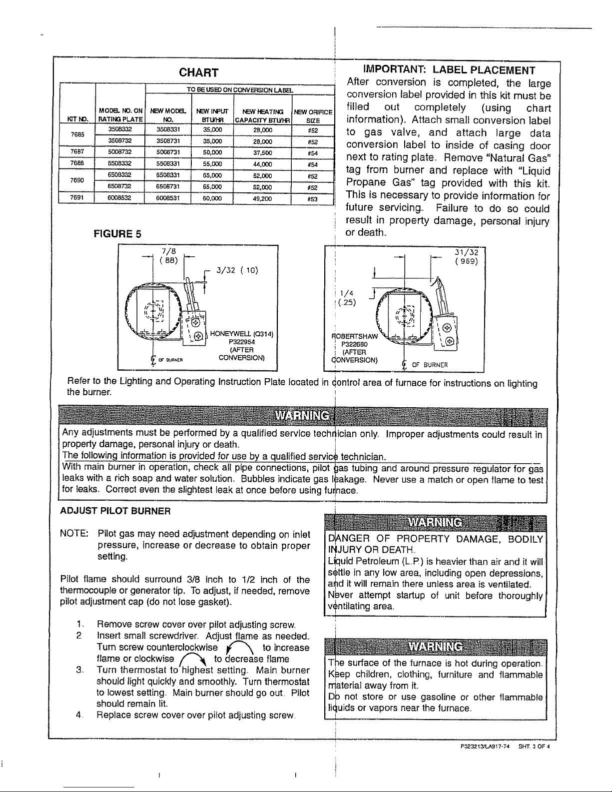
FIGURE 5
CHART
TO BE USI_ ON CONVICTION LABEL
NEW MOD_
NO.
3508331
3508731
50(38731
5508331
6508331
6508731
6008531
PEW INPUT
BI'UtHR
35,(X)0
35,000
5O,000
55,000
65,000
65,000
7/8
- (_8)
_ DURNg_I
NEWHEATING
DAPACITY BTLt91R
2B,000
28,000
37,500
44,000
52,000
52,000
60,000 49,200
.r- 3/_2 (lo)
HONEYWELLP322.954(Q314}
(AFTER
CONVERSION)
i
OFJRCE
SIZE
#52
#52
#54
#54
#52
#52
#53
IMPORTANT: LABEL PLACEMENT
After conversion is completed, the large
conversion label provided in this kit must be
filled out completely (using chart
information). Attach small conversion label
to gas valve, and attach large data
conversion label to inside of casing door
next to rating plate° Remove "Natural Gas"
tag from burner and replace with "Liquid
Propane Gas" tag provided with this kit.
This is necessary to provide information for
future servicing. Failure to do so could
result in property damage, personal injury
or death.,
t
(,,25) (I S
ROBERTSHAW "_L-__._=
! P3226B0 _
I (AFTER
dONVERSION)
0£ BURNER
,
Refer to the Lighting and Operating Instruction Plate located in _ontrol area of furnace for instructions on lighting
the burner°
I
Any adjustments must be performed by a qualified service techr dcian only. Improper adjustments could result in
property damage, personal injuryor death., t
!
The following information is provided for use by a qualified servic_ technician.
With main burner in 0peration, check aii"pipe connections, pilot _jas tubin'g"and around pressure regulator for gas
leaks with a rich soap and water solution. Bubbles indicate gas t_akage. Never use a match or open flame totest
for leaks. Correct even the slightest leak at once before using fu!nace.
ADJUST PILOT BURNER
NOTE: Pilot gas may need adjustment depending on inlet
pressure, increase or decrease to obtain proper
setting,.
Pilot flame should surround 3f8 inch to 1/2 inch of the
therrnocouple or generator tip, To adjust, if needed, remove
pilot adjustment cap (do not lose gasket).
i. Remove screw cover over pilot adjusting screw,
2 insert small screwdriver. Adjust flame as needed°
Turn screw counterclockwise _ to increase
flame or clockwise _ to _ecrease flame
3o Turn thermostat to-highest setting. Main burner
should light quickly and smoothly. Turn thermostat
to lowest setting,. Main burner should go out. Pilot
should remain liL
4 Replace screw cover over pilot adjusting screw.
t
D[ANGER OF PROPERTY DAMAGE, BODILY
iNJURY OR DEATH,
L_uid Petroleum (L,P,) is heavier than air and it will
s_)ttle in any low area, including open depressions,
a_d it will remain there unless area is ventilated°
Nbver attempt startup of unit before thoroughly
v+ntilating area,
children, clothing, furniture and flammable
t
P323213,.'LA_l 7_74 SHT. 3 OF 4
Page 3

CHECK GAS PRESSURE
J w
The minimum inlet pressure in the gas supply pipe should be 111,0 w,c, for Propane Gas., The maximum inlet
pressure should never exceed 13" w_c- This should be checked at the 1/8 inch N.,PT, plugged tapping in the supply
line with a manometer,
The manifold pressure for this appliance is !0,5" w,c, for Propane!Gas, Check with a manometer at the pressure tap
on the control valve,, To adjust pressure, remove ca_from! regulator and turn regulator adjustment screw
clockwise _ to increase and counterclockwise _ X, _ decrease pressure,
RATE VERIFICATION
Refer to the Lighting and Operating Instruction Plate located in cdntrol area of furnace for instructionson lighting the
burner.
I_ Make certainthereisno gas flowthroughthemeterothertha41otheappliancebeingchecked,Otherappliances
must remainoffand thepilotsextinguished(ortheirconsum#tiondeductedfromthemeterreading),
2. With gas control knob in "ON" position, cycle main burner o_ and off several times by means of thermostat to
stabilize PRV diaphragm,, i
3, With second hand on watch, carefully clock gas meter to detet'mine exact rate of gas flow to main burner in cubic
feet per hour (see CONVERSION TABLE below)° ,,
4. Compare actual input with manufacturer's recommended houily input stamped on rating platen Convert BTU per
hour input rating to cubic feet of gas per hour (cfh) by using _e following formula.
Whereas: Input Rating in BTUperHouJr = Cubic Feet of
PRV= Pressure BTU Content of Gas per cu tt Gas per Hour
RegulatorValve
MJ = Megajoule Input Rating in MJ/hr = m3ihr
m3 = MetricCube MJ of Gas per m3
5. If actual gas flow (cfh) does not conform to manufacturer's r_commended input rating (cfh or_U converted to
cfh), a limited adjustmen_tof the PRV may be made. Turn PI_V adjusting screw clockwise [ % to increase
or counterclockwise / "\ to decrease gas flow. Burne_ input must not exceed nameplate rating.
6. Replace cap screw in PRV adjustment stack. Turn gas suppl,/to other appliances back on and re4ight all pilots.
7o Place furnace in operation and observe through at least one €omplete cycle to be sure all controls are operating
satisfactorily., i
co"w"s'o"
This table shows the gas flow rate for measured time per revolution of the ONE CUBIC Foot
DIAL in cubic feet per hour (=th) and m3/hr.
,i ,,,,,,i ,H,, ,
TIM_ FLOW
sec cfh
40 90
......... ,,, ,,,
41 88
42 86
43 84
44 82
45 80
46 78
47 77
....... | ,,,,,,
75
73
72
FLOW TIME
m3/hr sec
2.55 56
2.50 57
5B
FLOW
cfh
64
63
62
2.44
2.38
2,32
2.21
.... , =
2.18
2,12
2.07
2,04
59
6O
62
64
66
68
70
6t i 1.73
60 _ 1.70
5B I 1.64
5s !1,59
54 ,,i,,,1.53
53 _ 1.50
51 il 1.44
FLOW TIME
m3/hr sec
}1.81 88
11.78 g2
= ................. __ ....
I 1,76 96
48
49
5O
51 71 2.01
52 69 1.95
53 68 1.93
54 67 1.90 80 _ 45
e5 ...........
For 1/2 cu froper revolution of meter dial, multiply
For 2 cu, ft. per revolution of meter dial, diTde flow
74 49
76 47
78 46
..........72 ...... i,50 _} 1.42-'
I 1_39
! 1.33
! !.3o
1.27
I 1.22
FLOW
cfh
41
39
38
36
34
33
31
30
29
I00
105
110
115
120
125
130 28
135 27
140 26
150 24
160 23
170 21
180 20
rate by 2.
by 2,
FLOW
m3/hr
1.16
1.10
1.o8
1.02
.96
.93
.88
.85
.82
.79
.76
,74
.68
.65
.59
.57
REV 6-'00
P3232134LA917..74
SH'f 4 OF 4
|
Page 4

FIGURE 1
BRACKET
OTEMI)
SCREWJ_
CONTROL ASSEMBLY
FOR MODELS
3508332; 3508732 (shown)
50087'32; 5508332 (not shown)
6508732; 60DB532 (not shown)
PILOT
BURNER
2)
I
_'- SCREW
FIGURE 2
A
INTERMITTENT JGNITJDN SYSTEMS
PILOT BURNER
STAMPED 3S24F
i /FORIFICE (LP SHOWN)
/STAMPED 11LP
#
/
B
HIGH BTU
BUILT-fN THERMOSTAT MODELS
PILOT BURNER
STAMPED Q314AFK
ORIFIC{ (UP, SHOWN)
(RED MARKING ON L.,P ORIFICE)
STAMPED BBRIO
t
i /r_PilO T
tlJ ,u==o
,/,/ PILOT HOOD
FIGURE 3
I_RESSURE REGULATOR CONVENIENCE
(,_NNNDU_TMEN'T TERMINALS [2) / WIRING
ER CAP SCREW)\\ (OPI3ONAL) i " / TERMINALS (2)
i£
! _R_SURE TAP, _ _ _'I/IUET_uRE
dO.N=CTiON,! A/.1 '_s \_ILOTADJUSTMENT
.ES_ COBOL(UNOE.CAPS_
BUTTON KI_K_B
A THERMOGOUPLE CONNECTION AND RED RESET
BUTTON ON STANDING PILOT MODELS ONLY
I FIGURE 4
PRESSURE
REGULATOR
HOUS1NG
!
1
P323213/L.A_17_74 SHT 2 OF ,_
 Loading...