

Williams 6038531, 6058531, 6008532A, 6018532A, 6058532A Owner's Manual
...
Do not store or use gasoline or other
flammable vapors and liquids in the vicinity
of this or any other appliance.
WHAT TO DO IF YOU SMELL GAS:
Open all windows.
Do not try to light any appliance.
Do not touch any electrical switch; do not
use any phone or cell phone in your
building.
Extinguish any open flame.
Immediately call your gas supplier from
a neighbor’s phone. Follow the gas
supplier’s instructions.
If you cannot reach the gas supplier,
call the fire department.
Installation and service must be performed
by a qualified installer, service agency or
the gas supplier.
WARNING: If the information in these
instructions is not followed exactly, a fire or
explosion may result causing property
damage, personal injury or loss of life.
Owner’s Manual Save this manual for future reference.
Magnum Forsaire
Counterflow Top-Vent Gas
Williams Furnace Co. 250 West Laurel Street Colton, California 92324 U.S.A.
Wall Furnace
Model Numbers:
6008532; 6038532; 6058532
FOR USE WITH NATURAL GAS ONLY
Model Numbers:
6008531; 6038531; 6058531
FOR USE WITH PROPANE GAS ONLY
READ THIS OWNER’S MANUAL CAREFULLY BEFORE YOU
INSTALL YOUR NEW WILLIAMS WALL FURNACE.
WARNING: Improper installation, adjustment,
alteration, service or maintenance can cause injury
or property damage. Refer to this manual. For
assistance or for additional information consult a
qualified installer, service agency or the gas
supplier.

Warranty & Installation Record – 2
Warranty
The manuf acturer, Williams Furnace Co., warrants this wall f urnace or heater to the original purchaser under the f ollowing conditions:
LIMITED ONE-YEAR WARRANTY
1. Any part thereof which prov es to be defective in material or workmanship within one year from date of original purchase for use will be replaced at the Manuf ac turer’s
option, FOB to its factory .
2. No liability is assumed by the Manufacturer f or removal or installation labor costs, nor for freight or delivery charges.
LIMITED EXTENDED WARR ANTY
1. In addition to the abov e limited one-year warranty on the complete unit, any combustion chamber which burns out or rusts under normal installation, use and service
conditions during a period of nine years following expiration of the one-year warranty period will be exchanged f or a like or f unctionally similar part.
2. No liability is assumed by the Manufacturer f or removal or installation labor costs, nor for freight or delivery charges.
LIMITATION S
1. THIS LIMITED WARRANTY IS THE ONLY WARRANTY MADE BY THE MANUFACTURER, IMPLIED WARRANTIES OF MERCHANTABILITY OR FITNESS FOR ANY
PARTICULAR PURPOSE ARE LIMITED TO THE SAME ONE YEAR TERM AS THE EXPRESS WARRANTY. UNDER NO CIRCUMSTANCES SHALL THE
MANUFACTURER BE LIABLE FOR INCIDENTAL, CONSEQUENTIAL, SPECIAL OR CONTINGENT DAMAGES OR EXPENSES ARISING DIRECTLY OR INDIRECTLY
FROM ANY DEFECT IN THE PRODUCT OR ANY COMPONENT OR FROM THE USE THEREOF. THE REMEDIES SET FORTH HEREIN ARE THE EXCLUSIVE
REMEDIES AVAILABLE TO THE USER AND ARE IN LIEU OF ALL OTHER REMEDIES.
Some states do not allow limitation on how long an implied warranty lasts, and some states do not allow the exclusion or limitation of incidental or consequential
damages, so the above limitations or exclusions may not apply to you.
2. This warranty does not include any charge for labor or installation.
3. This warranty does not extend to painted surfaces or to damage or defects resulting from accident, alteration, misuses or abuse or improper installation.
4. This warranty does not cov er claims which do not involv e defective workmanship or materials.
DUTIES OF THE CONSU MER
1. The heating equipment must be installed by a qualified installer and operated in accordance with the installation and homeowner’s instruct ions f urnis hed with the
equipment.
2. Any trav el, diagnostic costs, service labor, and labor to repair the defectiv e unit will be the responsibility of the owner.
3. A bill of sale, cancelled check, payment record or permit should be kept to v erify purchase date to establish the warranty period.
4. Hav e the installer enter the requested information in the space below.
GENERAL
1. The manuf acturer neither assumes nor authorizes any person to assume f or it any other obligation or liability in connection with said equipment.
2. Service under this warranty should be obtained by contacting your dealer. Provide the dealer with the model number, serial number, and purchase date v erification.
3. If , within a reasonable time after contacting your dealer, satisfactory service has not been received, contact: Customer Service Department, 250 West Laurel Street,
Colton, CA 92324 f or assistance.
4. THIS WARRANTY GIVES YOU SPECIFIC LEGAL RIGHTS AND YOU MAY ALSO HAVE OTHER RIGHTS WHICH VARY FROM STATE TO STATE.
Installation Record
Model No. ____________________________________________________________ Serial No.__________________________
Original Purchaser________________________________________________________________________________________
Address ________________________________ _______________________________________________________________
City and State _________________________________________________________ Zip _______________________________
Dealer ________________________________________________________________________________________________ _
Address ________________________________ _______________________________________________________________
City and State _________________________________________________________ Zip _______________________________
Installation Date ______________ Name ________________________________ Signature_________________________________
(Dealer or authorized representativ e who certifies that this appliance is installed in accordance with Manuf acturer’s inst ruct ions and loc al c odes. )
2

Contents
Your Williams Warranty .........................................................................2
Installation Record..................................................................................2
Table of Contents ...................................................................................3
Safety Rules ............................................................................................4
Introduction..............................................................................................5
Basic Description....................................................................................5
Basic Tools Needed ...............................................................................5
Basic Materials Needed ........................................................................5
Optional Accessories.....................................................................6
Installing Your Wall Furnace.................................................................7
Locating Wall Furnace and Thermostat.......................................... 7-8
Combustion and Ventilation Air......................................................8-11
Installation
Recessed Mount Installation............................................. 11-13
Surface Mount Installation................................................. 13-14
Vent Installation................................................................... 14-16
Mounting Your Furnace ................................................................ 16-17
Gas Supply and Piping ................................................................. 18-19
Electrical Wiring ................................................................................... 19
Thermostat Installation ....................................................................... 20
Optional Accessory Installation ................................................... 21-23
Start Up Procedure ............................................................................. 24
Operating Your Furnace............................................................... 25-26
How To Care For Your Furnace.................................................. 27-28
Furnace Technical Information.......................................................... 28
TROUBLESHOOTING CHART................................................... 29-30
Wiring Diagrams .................................................................................. 30
Repair Parts ................................................................................... 31-32
Repair Parts List ............................................................................ 33-34
Forsaire Hardwire Accessary - 9940 ................................................ 35
SERVICE HINTS ................................................................. Back Cover
How To Order Repair Parts ............................................... Back Cover
Quick Reference: Here’s how to…
Unpack the furnace ............................................................................... 6
Learn how to unpack the new Williams Furnace and verify that all
its parts are in working order.
Install the furnace ............................................................................ 7-20
Recessed Mount, Surface Mount, and Vent Installation is all
explained starting on page 11.
Operate the furnace ...................................................................... 25-26
Igniting the furnace for the first time.
Caring for Your Furnace ............................................................... 27-28
Learn how to keep your new Williams Furnace operating.

Safety Rules
WARNING: Read these rules and the instructions
carefully. Failure to follow these rules and
instructions could cause a malfunction of the
furnace. This could result in death, serious bodily
injury and/or property damage.
INSTALLATION MUST CONFORM TO LOCAL CODES. IN THE
ABSENCE OF LOCAL CODES, INSTALLATION MUST
CONFORM TO THE NATIONAL FUEL GAS CODE, ANSI Z223.1.
THE APPLIANCE, WHEN INSTALLED MUST BE
ELECTRICALLY CONNECTED AND GROUNDED IN
ACCORDANCE WITH LOCAL CODES OR, IN THE ABSENCE
OF LOCAL CODES, WITH THE CURRENT NATIONAL
ELECTRICAL CODE ANSI/NFPA NO. 70.
In Canada:
1. Installation must conform to local codes or, in
the absence of local codes, the current
CAN/CGA B149 installation code.
2. The appliance, when installed, must be
electrically connected and grounded in
accordance with local codes or, in the absence
of local codes, with the current CSA C22.1
Canadian Electrical code.
3. Field conversions for high altitude are not
permitted in Canada.
4. Reference is made in this manual regarding gas
type as L.P.G. Be advised that L.P.G. is not
available in Canada, refer to propane/L.P. Gas.
1. Use only manufacturer's replacement parts. Use of any
other parts could cause injury or death.
2. DO NOT install this furnace where it could be isolated by
closing doors to the heated space.
3. DO NOT install this furnace in a travel trailer or
recreational vehicle.
4. MAINTAIN all clearances specified in section "Locating
Wall Furnace and Thermostat".
5. BE SURE this furnace is for type of gas to be used.
Check the rating plate by the gas valve in the lower
cabinet. Do not change it to use other gases without the
proper manufacturer’s Gas Conversion Kit.
6. For natural gas, the minimum inlet gas supply pressure
for the purpose of input adjustment is 5" water column.
The maximum inlet gas supply pressure is 7" water
column.
For L.P. Gas, the minimum inlet gas supply pressure for
the purpose of input adjustment is 11" water column. The
maximum inlet gas supply pressure is 13" water column.
7. Any safety screen, guard or parts removed for servicing
this appliance must be replaced prior to operating the
appliance to avoid property damage, bodily injury or
death.
8. Install the furnace vent directly to the outdoors so that
harmful combustible flue gases will not collect inside the
building. Follow the venting instructions for your type of
installation exactly. Use only the type and size of vent
pipe and fittings specified.
9. BE SURE to provide for adequate combustion and
ventilation air. The flow of this air to the furnace must not
be blocked.
10. NEVER vent flue gases into another room, a fireplace or
any space inside a building. This could cause property
damage, bodily injury or death.
11. Never test for gas teaks with an open flame. Use a soap
solution to check all gas connections. This will avoid the
possibility of fire or explosion.
12. ALLOW the furnace to cool before servicing. Always shut
off electricity and gas to furnace when working on it. This
will prevent any electrical shocks or burns.
13. DUE TO HIGH TEMPERATURES, locate the furnace out
of traffic and away from furniture and draperies.
14. ALERT children and adults to the hazards of high surface
temperatures and warn them to keep away to avoid
burns or clothing ignition.
15. CAREFULLY supervise young children when they are in
the same room with the furnace.
16. DO NOT place clothing or other flammable material on or
near furnace.
17. INSTALLATION and REPAIR must be done by a qualified
service person. The appliance should be inspected
before use and at least annually by a professional
service person. More frequent cleaning may be required
due to excessive lint from carpeting, bedding material,
etc. It is imperative that control compartments, burners
and circulating air passages be kept clean.
18. BEFORE INSTALLING: To avoid electrical shock, tum off
electrical circuits that pass through the wall where you
are going to install the furnace.
19. BE AWARE of good safety practices by wearing personal
protective equipment such as gloves and safety glasses
to avoid being injured by sharp metal edges in or around
furnace and while cutting or drilling holes in wood and/or
sheet metal.
WARNING: Do not use this furnace if any part has
been under water. Immediately call a certified
service technician to inspect the furnace and to
replace any part of the control system and any gas
control which has been under water.
WARNING: Do not install any of these furnaces
(Natural or L.P. Gas) in mobile homes, trucks or
recreational vehicles.
4

Introduction – 5
Introduction
Please read our instructions before you install and use your furnace. This will help you obtain the full value from this furnace. It will also
help you avoid any needless service costs if the answer to the problem is found within this instruction manual.
Basic Description
Your Counterflow Top Vented Wall Furnace is shipped ready
to install on the surface of a wall or recessed up to 9-1/4 inches
in a wall, with wall studs spaced 16 inches center to center.
Vent piping and exhaust are not part of the Williams furnace
package and must be purchased separately.
Always consult your local heating or plumbing inspector,
building department or gas utility company regarding
regulations, codes or ordinances which apply to the installation
of a counterflow top vented wall furnace.
Air is drawn in at the top by the fan and discharges through a
grille near the floor. A two-speed fan is used with all models.
The furnace contains multi-slot burners and burns either
Natural or L.P. (Liquefied Petroleum) Gas, depending on the
model you have purchased.
This appliance is equipped with a vent safety shutoff system
designed to protect against improper venting of combustion
products. Operation of this wall furnace when not connected to
a properly installed and maintained venting system or
tampering with the vent safety shutoff system can result in
carbon monoxide (CO) poisoning and possible death.
The combustion system draws combustion air directly from the
room in which the furnace is installed, and through ventilation
grilles or ducts connected to the outdoors, such as an attic or
crawl space. The combustion gases are discharged through
the roof within a listed vent pipe.
The furnace heat exchanger is built of heavy gauge steel
treated for corrosion resistance, The fan at the top forces air
down along the front, back and sides of the heat exchanger
where it is discharged into the room, The furnace cabinet is
also constructed of heavy gauge steel and has a neutral beige
color enamel paint finish.
The furnace controls are located behind an access door on the
lower front of the furnace. AII models are equipped with
American Gas Association listed gas valves and pilots.
Tools Needed
Hand drill or properly grounded electric drill
Expansion bit 1/2" to 1-5/8" or 1/2'' and 1-1/2" blade bits
1/8" and 3/16" drill bit (metal)
6 ft. folding rule or tape measure
Screwdriver (med. blade)
Screwdrivers (Phillips Head)
Pliers (wire cutting)
Hammer
Hole Saw - 2"
1/8" Allen wrench
Stud locator or small finishing nails.
Tin snips
8 and 12" adjustable wrenches
Keyhole or sabre saw
2 - 10" or 12" pipe wrenches
Gloves and safety glasses
Materials
Pipe and fittings to make connections to furnace (See page 18).
Caulking compound-silicone rubber with a temperature rating of
500F.
DO NOT use caulking advertised as paintable or for bath tub use
as most contain fillers and will not withstand high temperatures.
Pipe Joint Compound resistant to L.P. gases.
Electrical wiring supplied as needed (see page 19).
Minimum wire size is #14 gauge copper.
3/4" Quarter Round or other wood trim molding approximately
16' long or Trim Accessory 4791 is recommended.
2" x 4" x (length as required) Spacer Blocks (see Close
Off Stud Space, page 12).
Oval Vent Kit 9901 is recommended.
Vent Enclosure Kit 9812 or 9824 if furnace is to be surface
mounted is recommended.
1 x 1 wood strips if Optional Side Outlet Grille Register
6701 is used.
Helpful Installation Information
The following booklets will help you in making the installation:
ANSI/NFPA 70-1990 or current edition "National Electrical Code". In Canada: CSA C22.1 Canadian Electrical Code.
American National Standard NFPAS4/ANSI Z223.1 1988 or current edition "National Fuel Gas Code".
Obtained from: American National Standards Institute, Inc., 1430 Broadway, New York, N Y 10018.
In Canada: CAN/CGA B149.
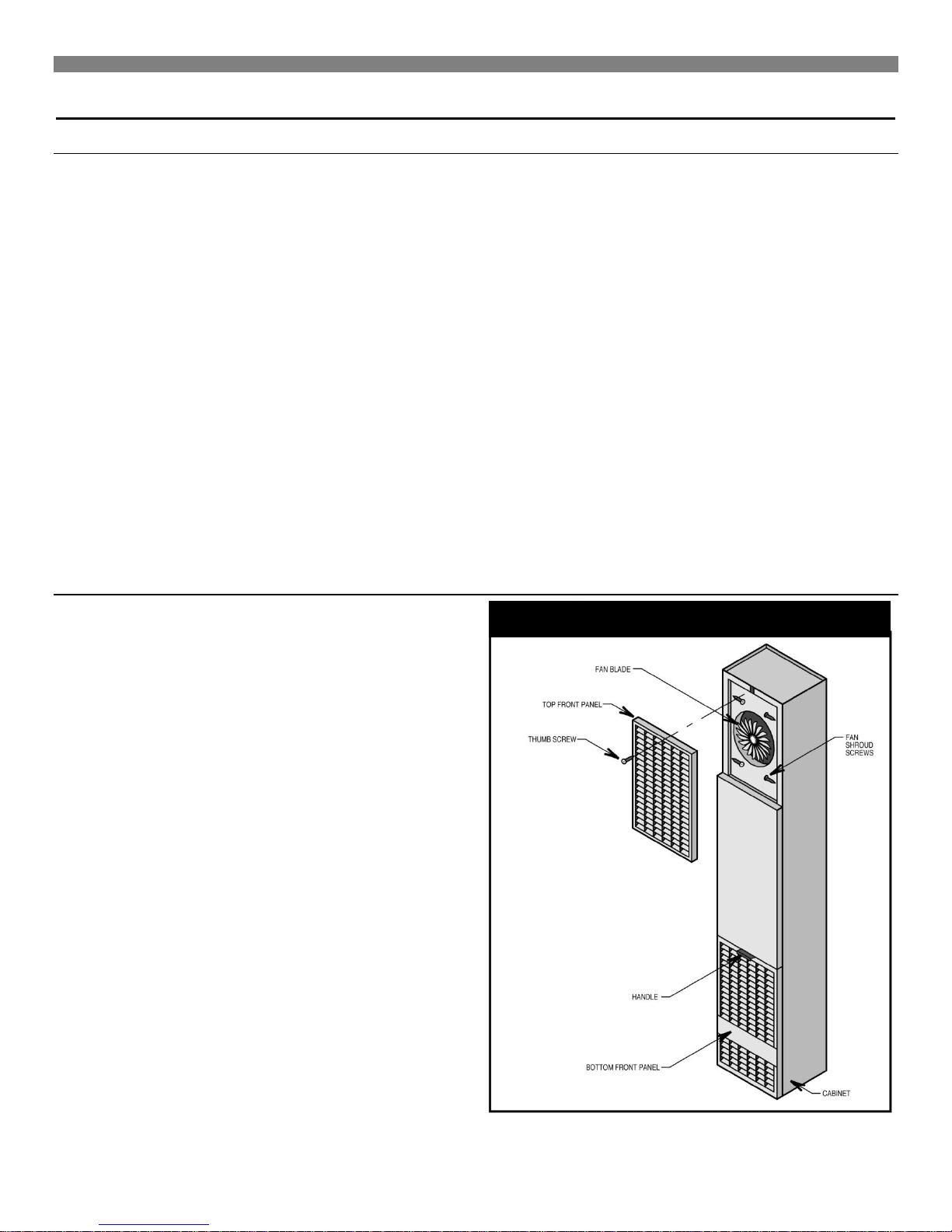
FIGURE 1
Introduction
Optional Accessories
SIDE OUTLET REGISTER 6701 Pg. 21
Let’s you route some heated air to a second room. Mounts on side
wall of second room and must be within 10 inches of wall furnace.
DIFFUSER GRILLE KIT 6703 as shown on Page 23, Fig. 32
Let’s you route some heated air in a two-way direction. Kit 6704
for one-way direction.
REAR OUTLET KIT 6801
Let’s you route some heated air to a second room behind the
furnace. Finished wall of second room must be within 10 inches of
furnace as shown on Page 8, Fig. D. Built-in damper lets you shut
off air flow to second room if desired.
SHORT REAR OUTLET KIT 6802
Let’s you route some heated air to a second room behind the
furnace when furnace is recessed mounted. Built-in damper lets
you control the air flow to the second room.
TRIM STRIP KIT 4701
OVAL VENT KIT 9901
This U.L. listed B/W vent kit contains 4 feet of oval double walled
vent pipe, plate spacers and starter or hold-down plate that starts
the venting from the top of the furnace. See page 16 for additional
items you will need.
VENT ENCLOSURE KITS 9812 or 9824
These kits are used only when the furnace is surface mounted.
They enclose the vent pipe from the top of the surface to the
ceiling.
SIDE OUTLET GRILLE KIT 6702 as shown on Page 22, Fig. 31
Allows you to direct heated air from the side of furnace into the
same room.
NOTE.
AII kits are identified on the carton by their Manufacturing Number
respectively, 6701, 6703, 6704, 6801, 6802, 4701, 9901, 9812,
9824 and 6702. These numbers are also listed on the furnace
rating plate.
Provides finished edge at sides of wall furnace. Neutral beige
enamel painted steel.
Unpack Your Furnace
The furnace is shipped in one carton containing the furnace,
installation instruction booklet and hardware bag.
1. Lay carton horizontally. Open carton and remove top trim
cover from its packing. Remove thumb screw at top of
furnace, raise top front panel ½ inch and remove panel from
cabinet. This is so you can get to the electrical connections
later.
2. Place these and other parts, as they are removed from
furnace, where they cannot be lost or damaged before you
need them.
3. Bottom front panel can be removed by grasping just below
handle and pulling it outward and then upward. See Fig. 1.
NOTE
Check the burner rating plate, located in burner compartment, to
make sure your furnace is equipped to operate on the type of gas
available (either Natural or L.P. Gas). Do NOT convert unit from
Natural Gas to L.P. Gas or from L.P. Gas to Natural
4. Remove all literature and package containing thermostat, wire
and metal anchors used for free standing installation.
5. Check the fan blade to be sure it spins freely.
6
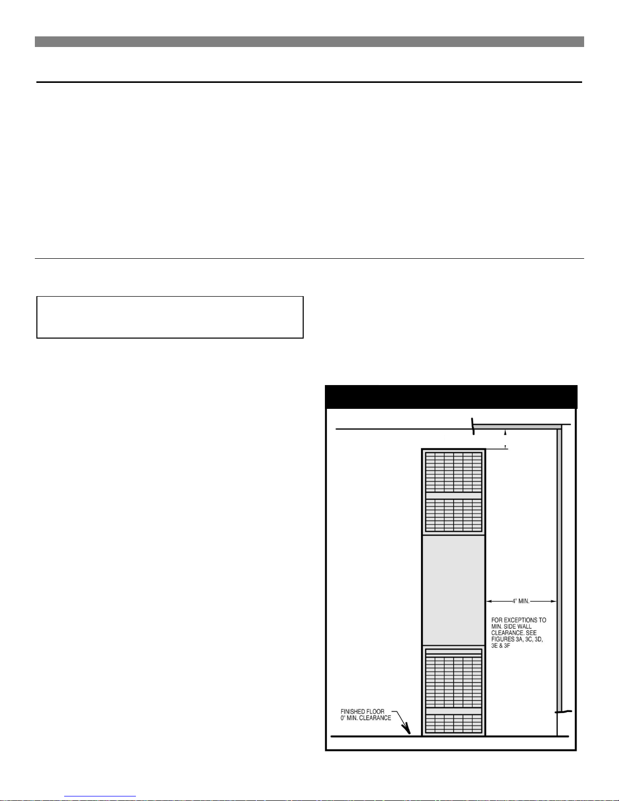
FIGURE 2 Minimum Clearances
CEILING CLEARANCE 2″ MIN
Installing Your Furnace
The following steps are needed for proper installation and safe
operation of your furnace. If you have any doubts as to any
requirements, always consult your local Heating or Plumbing
lnspector, Building Department or Gas Utility Company regarding
regulations, codes, or ordinances which apply to the installation of
a vented wall furnace. Obtain professional help where needed.
The CHECK AND ADJUSTMENTS on page 24 are vital to
the proper and safe operation of the furnace. Be sure they
are done.
IMPORTANT
For satisfactory and trouble-free operation, be sure to:
Locating Wall Furnace & Thermostat
Consider the following points before attempting to install the
furnace:
CAUTION: Do not make cut-outs in the wall or
ceiling before checking in the attic for ceiling joist
locations and proposed venting.
The counterflow vented wall furnaces are shipped ready to install
on the surface of the wall or recessed up to 9-1/4 inches into the
wall, with studs 16 inches center-to-center or stud space can be
framed to 16 inches, see page 11, Recessed Mounting.
1. Locate the furnace properly within the space to be heated.
2. Install the furnace in accordance with local codes or
ordinances and instructions provided. In the absence of local
codes or ordinances, install the furnace to conform with the
current edition of the National Fuel Gas Code, NFPA 54, ANSI
Z223.1/Canadian Installation Code, CAN/CGA B149.
3. Maintain minimum clearance: Floor 0 inches or ceiling 2
inches, side wall 4 inches. For exception to minimum side wall
clearance, as shown on Page 8, Fig. 3.
4. Provide enough combustion and ventilation air.
With standard furnace discharge outlet, do not install closer than 4
inches to intersecting wall. See figure as shown on Page 8, Fig.
3B.
When using optional kits 6703 or 6704 maintain clearances as
shown on Page 8, Fig. 3A or 3C.
When using optional kit 6704 maintain clearance as shown in
Figs. 3A and 3F, page 8. Use only optional outlet and grille kits
available from manufacturer.
Place the furnace near the center of the space to be heated for
good air circulation. Do not put it behind a door or draperies.
Do not instatl the furnace in a closet, alcove, of small hallway
where the furnace could be isolated by closing doors to the heater
space.
Do not install the furnace in a mobile home, trailer, or recreational
vehicle.
The bottom of the furnace may rest directly on a wood or concrete
floor, If floor is other than wood or concrete there must be a piece
of wood or sheet metal under the furnace that is at teast the same
size as the bottom of the furnace.
On recessed installations the recessed portion rnay have 0 inches
clearance to combustible material.
To provide adequate clearance and service access the front of the
furnace must face the open room. Be sure that gas piping and
electrical wiring can be brought to the location. See sections
covering piping and electrical wiring for your type of furnace
mounting.
Furnace vent must be installed directly to the outdoors so that
combustion gases will not collect inside the building.
Provide an adequate vent or flue in accordance with local codes
or ordinances and instructions provided by the vent pipe
rnanufacturer.
Check the minimum spacing needs as shown on Page 7, Fig. 2
and Page 8, Fig. 3.
The top of the furnace must be at least 2 inches from the ceiling.
See Fig. 2.
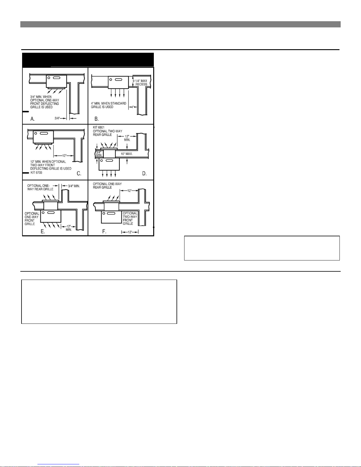
FIGURE 3 Minimum Clearances
Installing Your Furnace
With standard furnace discharge outlet, do not install closer than 4
inches to intersecting wall.
Choose a location for the thermostat about 5 feet above the floor
on an inside wall. The thermostat wire supplied with your furnace
is 20 feet long, which should be enough to run up through the attic
so the thermostat can be a maximum of 16 feet from the furnace
measured in a straight line, or approximately 12 feet from the
furnace if the wire is run under the floor. The thermostat should be
sensing average room temperature, avoid the following:
HOT SPOTS: COLDSPOTS:
Concealed pipes or ducts Concealed pipes or ducts
Fireplaces Stairwells – drafts
Registers Doors – drafts
TV sets Unheated rooms on
Radios other side of wall
Lamps
Direct sunlight DEAD SPOTS
Kitchen Behind doors
Corners, and alcoves
Combustion & Ventilation Air
WARNING: Danger of property damage, bodily
injury or loss of life. The furnace and any other fuelburning appliances must be provided with enough
fresh air for proper combustion and ventilation of
flue gases. Most homes will require that outside air
be supplied into the heated area.
The high cost of energy for home heating has brought about new
materials and methods used to construct or remodel most current
homes. The improved construction and additional insulation has
reduced the heat loss and made these homes much tighter
around windows and doors so that infiltrated air is minimal. This
creates a problem to supply combustion and ventilation air for
gas-fired or other fuel burning appliances. Any use of appliances
that pull air out of the house (clothes dryers, exhaust fans,
fireplaces, etc.) increases this problem and appliances could be
starving for air.
In addition, these energy measures mean that your home will
retain more water vapor or a higher relative humidity.
After picking a location that meets the requirements, check the
walls, attic and roof to make sure there are no obstructions such
as pipes, electric wiring, etc., which could interfere with the
installation of the furnace or vent pipe. If required, move them or
pick a new location.
WARNING: Danger of property damage, bodily
injury or loss of life. Do not install furnace in any
area where oxygen is in use.
High humidity, especially during cold weather, may be damaging
to buildings because condensation forms on windows and inside
walls.
The combination of a tight energy efficient home with the use of
exhaust fans, fireplaces, clothes dryers, and gas appliances res ult
in more and more air being drawn from the house until fresh air
may be sucked back into the house down a furnace flue or
fireplace chimney. Carbon monoxide can be the result. Carbon
monoxide (CO) is a colorless, odorless gas produced when fuel is
not burned completely or when the flame does not receive
sufficient oxygen. Automobiles, charcoal, wood fires and
improperly vented or air-starved coal, oil and gas furnaces or
other appliances can produce carbon monoxide.
Be aware of these air-starvation signals:
1. Headaches, nausea, dizziness.
2. Excessive humidity shown by heavily frosted windows or a
moist "clammy" sensation.
3. Fireplace smoke fills the room or will not draw.
4. Furnace flue backs up.
8
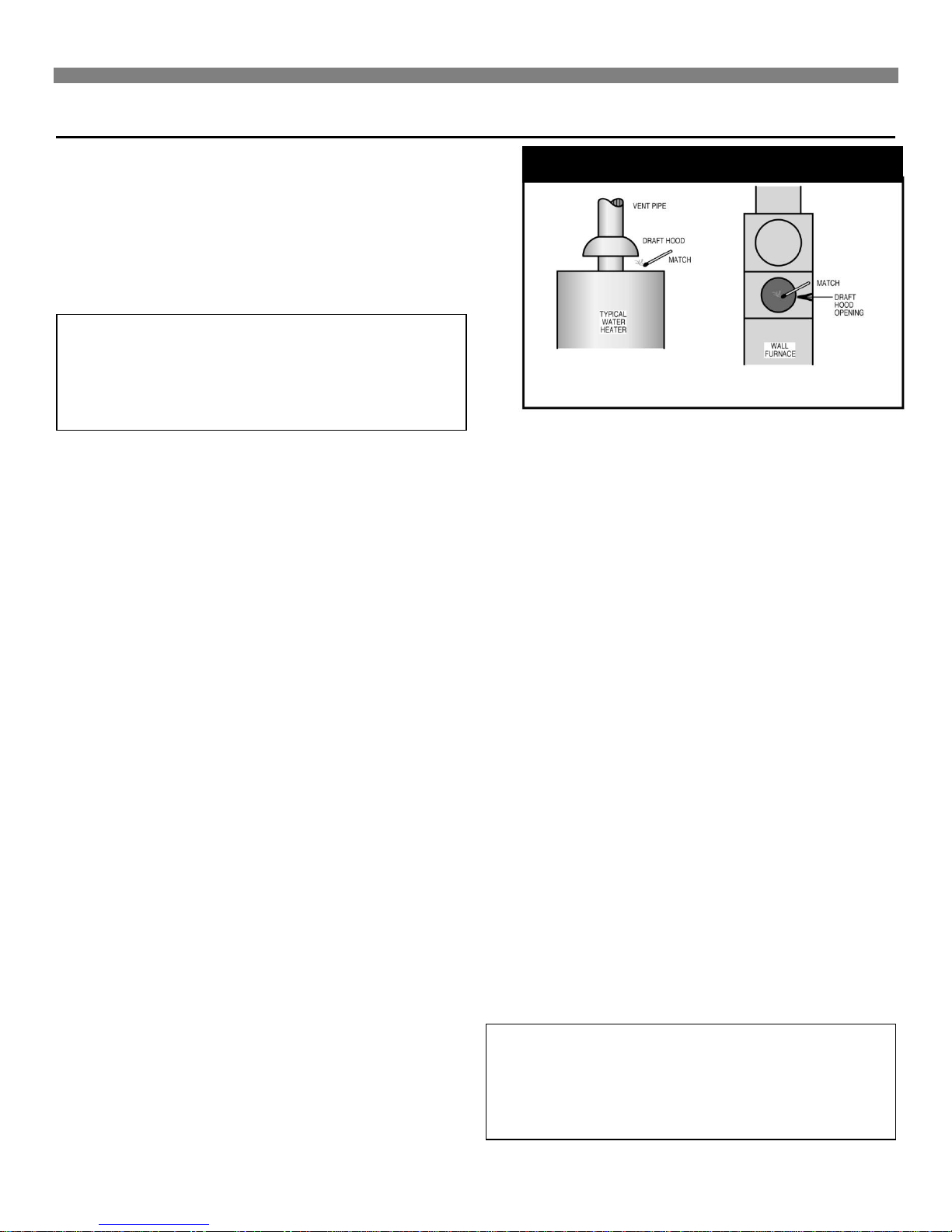
FIGURE 4 Draft Hood Spillage
Installing Your Furnace
AIR REQUIREMENTS
The requirements for providing air for combustion and ventilation
are listed in the National Fuel Gas Code NFPA 54/ANSI Z223.1 (in
Canada: CAN/CGA B149). Most homes will require that outside
air be supplied to the heated area by means of ventilation grilles
or ducts connecting directly to the outside or spaces open to the
outdoors such as attic or crawl space. The only exception is when
the heated area meets the requirements and definitions for an
unconfined space with adequate air infiltration.
WARNING: Danger of property damage, bodily
injury or loss of life. The furnace and any other fuelburning appliances must be provided with enough
fresh air for proper combustion and ventilation of
flue gases. Most homes will require that outside air
be supplied into the heated area.
All air openings and connecting ducts must comply with the
following:
If the furnace is installed in an area with another gas appliance(s),
the total input rating of all appliances must be considered when
determining the free area requirements for combustion and
ventilation air openings.
Ducts must have the same cross-sectional area as the free area
of the openings to which they connect. The minimum dimension
of rectangular air ducts must not be less than 3-inches in length or
height.
LOUVERS / GRILLES AND SCREENS COVERING
FREE AREA OPENINGS
If a screen is used to cover the opening(s), it must not be smaller
than 1/4-inch mesh. Use the free area of a louver or grille to
determine the size opening required to provide the free area
specified. If the free area is not known, assume a 20% free area
for wood and a 60% free area for metal louvers or grilles.
EXAMPLE 1
FURNACE LOCATED IN UNCONFINED SPACE.*
*
An unconfined space must have a volume of a minimum 50 cubic
feet per 1000 Btu/hr. of total of all appliances in area. Adjoining
rooms may be included only if there are no doors between the
rooms, or if special provisions are made such as ventilation grilles
installed between connecting rooms.
Fig 6, page 10 shows the minimum area in square feet' based on
8 foot ceiling heights, required for different Btu/hr. input ratings.
A. If your furnace is in an open area (unconfined space*) the
air that leaks through the cracks around doors and windows
may be enough for combustion and ventilation air. The doors
should not fit tight. The cracks around windows should not
be caulked or weather stripped.
To determine if infiltration air is adequate, following checks:
1. Close all doors and windows. If you have a fireplace,
start a fire and wait until flames are burning vigorously.
2. Turn on all exhausting devices, such as:
kitchen and bathroom exhaust fans
dryers (gas and electric)
3. Turn on all vented gas appliances, such as:
heating equipment (includes any room heaters)
water heater
4. Wait ten (10) minutes for drafts to stabilize.
5. Check for draft hood spillage at each appliance. (Hold a
lighted match 2 inches from draft opening. See Fig. 4.)
B. No Spillage
If the match flame pulls toward draft hood - this indicates
sufficient infiltration air:
1. Return exhausting devices and appliances to the
condition you found them.
C. Draft Hood Spills
If there is spillage at a draft hood (match goes out or flame
wavers away from draft hood):
1. Check for plugged flue connectors and chimneys. Check
and repair, stoppage and test again.
2. If you have a fireplace, open a window or door near the
fireplace and then check for spillage.
a) If spillage stops, do not use the fireplace without a
nearby window or door open until you can supply
fresh air by a permanent duct.
3. If you have kitchen and bathroom exhaust fans, turn
them off and check for spillage.
a) If spillage stops, do not use exhaust fans until you
can supply fresh air by a permanent duct.
WARNING: Danger of property damage, bodily
injury or loss of life. Draft hood spillage, with
unobstructed vents, indicates that additional air
must be brought into the structure from outside.
Keep a window open (minimum 2 inches) near the
appliance until a permanent air duct is installed.
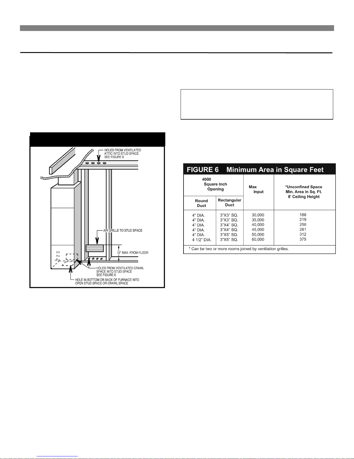
FIGURE 5 Fresh Air duct
Btu/hr. Per
Btu/hr.
Installing Your Furnace
4. Spillage means air starvation and a fresh air duct or air
intakes must be installed to provide air directly to the
furnace or other gas appliance.
D. If spillage exists or when the furnace is in a building of tight
construction where the windows and doors are weatherstripped, air for combustion and ventilation must be obtained
from outdoors or space open to the outdoors.
Provide an opening(s) having a total free area of 1-square inch
per 4000 Btu/hr. for the total of all appliances. The required area
is shown on page 11, Fig. 9 under the column for (40,000).
within 12 inches of the bottom of the room connecting directly to
unconfined space. Each opening must have a free area of at least
100 square inches or 1 square inch per 1000 Btuh combined input
of appliances in one room if combined input exceeds 100,000
Btuh.
WARNING: Danger of property damage, bodily
injury or loss of life. The adjoining unconfined
space must have adequate air infiltration as defined
in example 1.
FOR EXAMPLE: Your furnace is rated at 60,000 Btu/hr. The water
heater is rated at 30,000 Btu/hr. The total is 90,000 Btu/hr. You
need two grilles, each with 100 square inches of free opening.
Metal grilles have about 60% free area, so you need two metal
grilles each with 160 square inches of louvered area.
Fig 5 shows a typical duct going into ventilated crawl space
or attic.
1. Duct must terminate at a point not more than 1 foot
above the floor.
2. Duct size must be at least 1 inch of free area for each
4000 Btu/hr. of input of all appliances in area.
EXAMPLE 2.
FURNACE LOCATED IN CONFINED SPACE.
If furnace is installed in a confined space, it must be provided with
free air for proper combustion and ventilation of flue gases by one
of the following methods.
A. All Air From Inside Building:
If the confined space adjoins an unconfined, provide two
permanent openings, one within 12 inches of the top and one
Refer to figure as shown on Page 11, Fig. 7, which shows grille
installation. Using the previous example, the two connecting
rooms plus the closet must equal at least 500 sq. feet to handle
the combined input 60,000 plus 30,000.
B. All Air From Outdoors:
If confined space doesn't adjoin an unconfined space then air
must be provided from outdoors or spaces open to outdoors such
as attic or crawl space.
Provide two permanent openings, one within 12 inches of top, one
within 12 inches of bottom of room connecting directly, or by using
ducts, with the outdoors or areas open to outdoors.
If opening connects directly to, or within vertical ducts, the free
area of each opening must be at least 1 square inch per 4000
Btu/hr. combined input of appliances in area.
If horizontal ducts are used, the free area of each opening must
be at least 1 square inch per 2000 Btu/hr. combined input of
appliances in area.
10
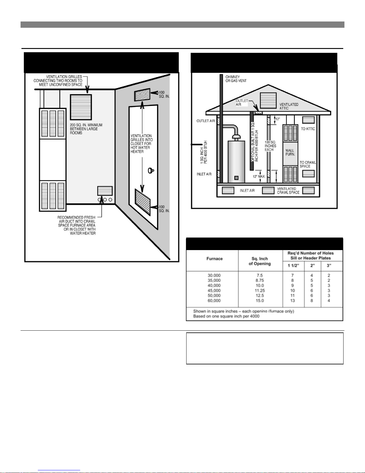
FIGURE 7 Grilles Connecting Rooms to
Make Unconfined space
FIGURE 8 Air from outdoors or crawl space
FIGURE 8 Air from Outdoors or Crawl
Space
FIGURE 9 Free Area
Btu/hr.
Btu/hr./Input
Installing Your Furnace
FOR EXAMPLE: Your furnace is rated at 60000 Btu/hr. The water
heater is rated at 30,000 Btu/hr. The total is 90,000 Btu/hr. You
need two grilles, each with 22½-square inches of free opening,
unless connected by horizontal ducts which would require each
grille or opening to have a free area of 45 square inches.
Recessed Mount Installation
FIND THE STUDS (See CAUTION on page 7)
Use a stud locator or small finishing nails. Repeatedly drive and
remove a nail into the wall in the area of the stud until it is located.
Then find the inside edge of the stud. Leave the nail at this
location.
The other stud should be about 14½-inches from the one found.
Drive finishing nails on the inside of this stud. Draw wall cutout to
required size as shown on Page 13, Fig. 13. If wall studs are not
on 16-inch centers see "CLOSE OFF STUD SPACE.” (As shown
on Page 12, Fig. 12).
CUT WALL OPENING
Provide an opening as shown on Page 12, Fig. 10. Work from the
top in the attic to cut away the ceiling plate.
*Openings for inlet or outlet air should not be made into attic area
if attic is equipped with a thermostat controlled power vent.
WARNING: BEFORE INSTALLING: To avoid
electrical shock, turn off electrical circuits that pass
through the wall where you are going to install the
furnace.
ATTACH HEADER PLATE
MODELS: 6008531; 6008532
Locate header plate between wall studs at 81 3/4 inches from
finished floor and nail into position with end flanges pointing up.
Make sure header plate is level.
ALL MODELS
Hole or electrical conduit is located on left side of header plate as
you face the wall.
 Loading...