

Williams 3501522A, 2011622A, 3511522A, 3531522A, 3551522A Owner's Manual
...
qualified installer, service agency or the gas
WARNING: If the information in these instructions
loss of life.
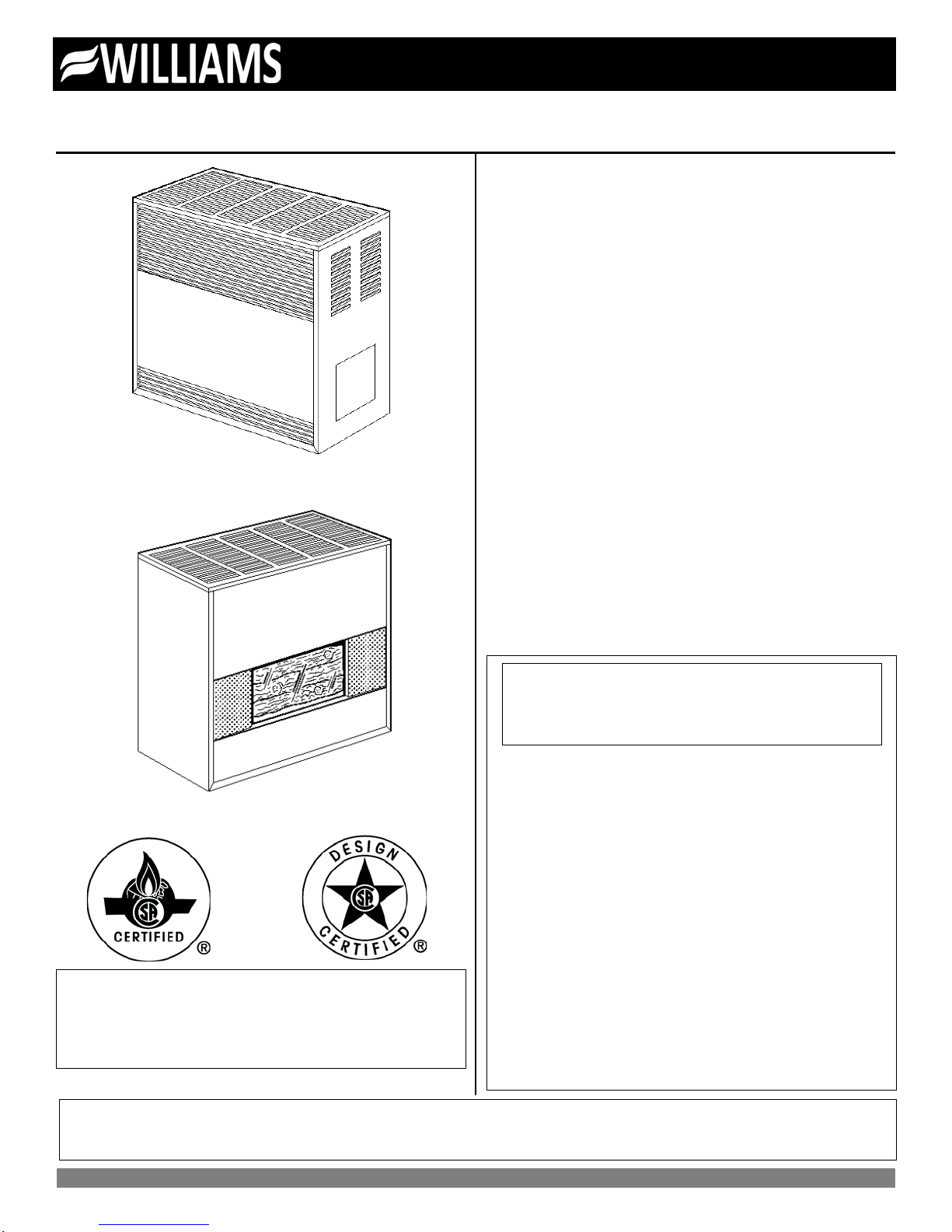
ENCLOSED MODEL
FIREPLACE MODEL
WARNING: Installation and repair must be done by a qualified service person. The appliance should be inspected
Owner’s Manual Save this manual for future reference.
Vented Room Heaters
Model Numbers:
2001622A; 2011622A; 2031622A; 2051622A; 3501522A; 3511522A;
3531522A; 3551522A; 3501922A; 3511922A; 3531922A; 3551922A;
3502522A; 3511522A; 3532522A; 3552522A; 3502922A; 3512922A;
3532922A; 3552922A; 5001522A; 5011522A; 5031522A; 5051522A;
5001922A; 5011922A; 5031922A; 5051922A; 5002522A; 5012522A;
5032522A; 5052522A; 5002922A; 5012922A; 5032922A; 5052922A;
6501522A; 6511522A; 6531522A; 6551522A; 6501922A; 6511922A;
6531922A; 6551922A; 6502522A; 6512522A; 6532522A; 6552522A;
6502922A; 6512922A; 6532922A; 6552922A
FOR USE WITH NATURAL GAS ONLY
Model Numbers:
2001621A; 2011621A; 2031621A; 2051621A; 3501521A; 3511521A;
WARNING: Improper installa tio n, adj ust ment, alteration,
service or maintenance can cause injury or property
damage. Refer to this manual. For assistance or for
additional information consult a qualified installer,
service agency or the gas supplier.
3531521A; 3551521A; 3501921A; 3511921A; 3531921A; 3551921A;
3502521A; 3512521A; 3532521A; 3552521A; 3502921A; 3512921A;
3532921A; 3552921A; 5001521A; 5011521A; 5031521A; 5051521A;
5001921A; 5011921A; 5031921A; 5051921A; 5002521A; 5012521A;
5032521A; 5052521A; 5002921A; 5011921A; 5032921A; 5052921A;
6501521A; 6511521A; 6531521A; 6551521A; 6501921A; 6511921A;
6531921A; 6551921A; 6502521A; 6512521A; 6532521A; 6552521A;
6502921A; 6512921A; 6532921A; 6552921A
FOR USE WITH LIQUEFIED PETROLEUM (L.P.) GAS ONLY
READ THIS OWNER’S MANUAL CAREFULLY BEFORE YO U IN STALL
YOUR NEW WILLIAMS HEATER.
is not followed exactly, a fire or explosion may
result causing proper ty damage, personal injur y or
Do not store or use gasoline or other flammable
vapors and liquids in the vi cinity of this or an y other
appliance.
WHAT TO DO IF YOU SMELL GAS:
• Open all windows.
• Do not try to light any appliance.
• Do not touch any electrical switch; do not
Installation and service must be performed by a
use any phone or cell phone in your building.
• Extinguish any open flame.
• Immediately call your gas supplier from a
neighbor’s phone. Follow the gas supplier’s
instructions.
• If you cannot reach the gas supplier, call the fire
department.
supplier.
before use and at least annually by a professional service person.
Williams Furnace Co. 250 West Laurel Street Colton, California 92324 U.S.A.

Warranty & Installation Record – 2
Warranty
The manufacturer, Williams Furnace Co., warrants this wall furnace or heater to the original purchaser under the following conditions:
LIMITED ONE-YEAR WARRANTY
1. Any part thereof which proves to be defective in material or workmanship within one year from date of original purchase for use will be replaced at the Manufacturer’s
option, FOB to its factory.
2. No liability is assumed by the Manufacturer for removal or installation labor costs, nor for freight or delivery charges.
LIMITED EXTENDED WARRANTY
1. In addition to the above limited one-year warranty on the complete unit, any combustion chamber which burns out or rusts under normal installation, use and service
conditions during a period of nine years following expirati on of the one -year warranty period will be exchanged for a like or functionally similar part.
2. No liability is assumed by the Manufacturer for removal or installation labor costs, nor for freight or delivery charges.
LIMITATIONS
1. THIS LIMITED WARRANTY IS THE ONLY WARRANTY MADE BY THE MANUFACTURER, IMPLIED WARRANTIES OF MERCHANTABILITY OR FITNESS FOR ANY
PARTICULAR PURPOSE ARE LIMITED TO THE SAME ONE YEAR TERM AS THE EXPRESS WARRANTY. UNDER NO CIRCUMSTANCES SHALL THE
MANUFACTURER BE LIABLE FOR INCIDENTAL, CONSEQUENTIAL, SPECIAL OR CONTINGENT DAMAGES OR EXPENSES ARISING DIRECTLY OR INDIRECTLY
FROM ANY DEFECT IN THE PRODUCT OR ANY COMPONENT OR FROM THE USE THEREOF. THE REMEDIES SET FORTH HEREIN ARE THE EXCLUSIVE
REMEDIES AVAILABLE TO THE USER AND ARE IN LIEU OF ALL OTHER REMEDIES.
Some states do not allow limitation on how long an implied warranty lasts, and some states do not allow the exclusion or limitation of incidental or consequential
damages, so the above limitations or exclusions may not apply to you.
2. This warranty does not include any charge for labor or installation.
3. This warranty does not ext end to painted surfaces or to damage or defects resulting from accident, alteration, misuses or abuse or improper installation.
4. This warranty does not cover claims which do not involve defective workmanship or materials.
DUTIES OF THE CONSUMER
1. The heating equipment must be installed by a qualified installer and operated in accordance with the installation and homeowner’s instructions furnished with the
equipment.
2. Any travel, diagnostic costs, service labor, and labor to repair the defective unit will be the responsibility of the owner.
3. A bill of sale, cancelled check, payment record or permit should be kept to verify purchase date to establish the warranty period.
4. Have the installer enter the requested information in the space below.
GENERAL
1. The manufacturer neither assumes nor aut horizes any person to assume for it any other obligation or liability in connection w ith sai d equipm ent.
2. Service under this warranty should be obtained by contacting your dealer. Provide the dealer with the model number, serial number, and purchase date verification.
3. If, within a reasonable time after contacting your dealer, satisfactory service has not been received, contact: Customer Service Department, 250 West Laurel Street,
Colton, CA 92324 for assistance.
4. THIS WARRANTY GIVES YOU SPECIFIC LEGAL RIGHTS AND YOU MAY ALSO HAVE OTHER RIGHTS WHICH VARY FROM STATE TO STATE.
Installation Record
Model No. ______________________________________________________________ Serial No. ___________________________
Original Purchaser ____________________________________________________________________________________________
Address ____________________________________________________________________________________________________
City and State ___________________________________________________________ Zip ________________________________
Dealer _____________________________________________________________________________________________________
Address ____________________________________________________________________________________________________
City and State ___________________________________________________________ Zip ________________________________
Installation Date _______________ Name ________________________________ Signature_________________________________
(Dealer or authorized representative who certifies that this appliance is installed in accordance with Manufacturer’s instructions and local codes.)
2

Contents
Your Williams Warranty ................................................................. 2
Installation Record ......................................................................... 2
Table of Contents .......................................................................... 3
Safety Rules .................................................................................. 4
Introduction .................................................................................... 5
Basic Des cription ........................................................................... 5
Basic Tools Needed ...................................................................... 5
Basic Materials Needed................................................................. 5
Optional Accessories ..................................................................... 5
Unpack Your Heater ...................................................................... 5
Installing Your Heater .............................................................. 6-15
Locating the Heater.......................................................... 6-8
Combustion & Ventilation Air ......................................... 8-11
Thermostat Installation ................................................. 11-12
Vent Installation ........................................................... 13-15
Operating Your Heater .......................................................... 16-18
Start Up Procedure ...................................................... 16-17
Operating Instructions ........................................................ 18
How To Care For Your Heater ............................................... 19-20
Repair Parts & Parts Lists ..................................................... 21-26
Blower Accessory 2102 ......................................................... 27-28
Troubleshooting Chart ........................................................... 29-31
SERVICE HINTS .......................................................... Back Cover
How To Order Repair Parts .......................................... Back Cover
Quick Reference: Here’s how to…
Unpack the heater......................................................................... 5
Learn how to unpack the new Williams Heater and verify that all
its parts are in working order.
Install the heater ...................................................................... 6-15
Thermostat and Vent Installation is all explained starting on page
8 thru 11.
Operate the heater ................................................................. 16-18
Igniting the heater for the first time.
Caring for Your Heater ........................................................... 19-20
Learn how to keep your new Williams Heater operating.

Safety Rules
WARNING: Read these rules and the instructions
carefully. Failure to follow these rules and
instructions could cause a malfunction of the
heater. This could result in death, serious bodily
injury and/or property damage.
INSTALLATION MUST CONFORM TO LOCAL CODES. IN THE
ABSENCE OF LOCAL CODES, INSTALLATION MUST
CONFORM TO THE NATIONAL FUEL GAS CODE, ANSI Z223.1.
THE APPLIANCE, WHEN INSTALLED MUST BE
ELECTRICALLY CONNECTED AND GROUNDED IN
ACCORDANCE WITH LOCAL CODES OR, IN THE ABSENCE
OF LOCAL CODES, WITH THE CURRENT NATIONAL
ELECTRICAL CODE ANSI/NFPA NO. 70.
In Canada:
1. Installation must conform to local codes or, in
the absence of local codes, the current
CAN/CGA B149 installation code.
2. The appliance, when installed, must be
electrically connected and grounded in
accordance with local codes or, in the absence
of local codes, with the current CSA C22.1
Canadian Electrical code.
3. Field conversions for high altitude are not
permitted in Canada.
4. Reference is made in this manual regarding gas
type as L.P.G. Be advised that L.P.G. is not
available in Canada, refer to propane/L.P. Gas.
1. Use only manufacturer's replacement parts. Use of any
other parts could cause injury or death.
2. DO NOT install the heater in an alcove.
3. DO NOT install this heater where it could be isolated by
closing doors to the heated space.
4. DO NOT install this heater in a travel trailer or
recreational vehicle.
5. MAINTAIN all clearances specified in section "Locating
Wall heater and Thermostat" and "Vent Installation."
6. BE SURE this heater is for the type of gas to be used.
Check the rating plate by the gas valve in the lower
cabinet. Do not change it to use other gases without the
proper manufacturer’s Gas Conversion Kit.
7. For natural gas, the minimum inlet gas supply pressure
for the purpose of input adjustment is 5" water column.
The maximum inlet gas supply pressure is 7" water
column.
For L.P. Gas, the minimum inlet gas supply pressure for
the purpose of input adjustment is 11" water column. The
maximum inlet gas supply pressure is 13" water column.
8. Any safety screen, guard or parts removed for servicing
this appliance must be replaced prior to operating the
appliance to avoid property damage, bodily injury or
death.
9. Install the heater vent directly to the outdoors, so that
harmful gases will not collect inside the building. Follow
the venting instructions for your type of installation
exactly. Use only the type and size of vent pipe and
fittings specified.
10. BE SURE to provide for adequate combustion and
ventilation air. The flow of this air to the heater must not
be blocked.
11. NEVER vent flue gases into another room, a fireplace or
any space inside a building. This could cause property
damage, bodily injury or death.
12. Never test for gas teaks with an open flame. Use a soap
solution to check all gas connections. This will avoid the
possibility of fire or explosion.
13. ALLOW the heater to cool before servicing. Always shut
off electricity and gas to the heater when working on it.
This will prevent any electrical shocks or burns.
14. DUE TO HIGH TEMPERATURES, locate the heater out
of traffic and away from furniture and draperies.
15. ALERT children and adults to the hazards of high surface
temperatures and warn them to keep away to avoid
burns or clothing ignition.
16. CAREFULLY s upervise young children when they are in
the same room with the heater.
17. DO NOT place cloth i ng or othe r fla mm a bl e m at e ri al on o r
near heater.
18. INSTALLATION and REPAIR must be done by a
qualified service person. The appliance should be
inspected before use and at least annually by a
professional service person. More frequent cleaning may
be required due to excessive lint from carpeting, bedding
material, etc. It is important that control compartments,
burners and circulating air passages be kept clean.
Failure to keep burner-control compartment and other
parts of heater clean can cause dangerous conditions to
develop which can cause injury and even death.
19. BEFORE INSTALLING the optional blower: To avoid
electrical shock, turn off electrical circuits that pass
through the wall where you are going to install the
heater.
20. BE AWARE of good safety practices by wearing personal
protective equipment such as gloves and safety glasses
to avoid being injured by sharp metal edges in or around
heater and while cutting or drilling holes in wood and/or
sheet metal.
21. CAUTION: Label all wires prior to disconnection when
servicing controls. Wiring errors can cause improper and
dangerous operation. Verify proper operation after
servicing.
22. DO NOT store or use gasoline or other flammable liquids
or vapors near the heater.
WARNING: Do not use this heater if any part
has been under water. Immediately call a
certified service technician to inspect the heater
and to replace any part of the control system and
any gas control which has been under water.
4

Introduction – 5
Introduction
Please read our instructions before you install and use your heater. This will help you obtain the full value from this heater. If the
answer to the problem is found within this instruction manual, it could help you avoid needless service costs.
Basic Description
Always consult your local heating or plumbing inspector,
building department or gas company regarding regulations,
codes or ordinances which apply to the installation of a vented
room heater.
No electrical power is required unless furnace is equipped with
an optional blower accessory.
The efficiency rating of this appliance is a product thermal
efficiency rating determined under continuous operating
conditions and was determined independently of any
installation system.
Warmed air is discharged into the room in which the heater is
located. The heater contains a single multi-slot gas burner.
Combustion air is drawn in from the room where the heater is
located and is vented out of the heater vertically through vent
piping to a roof vent top. (Vent equipment is not supplied with
the heater).
Basic Tools Needed
Hand drill or properly grounded electric drill
1/8 inch and 3/16 inch drill bit (metal)
6 foot folding ruler or tape measure
Screwdriver (Phillips Head)
Pliers (Wire Cutting)
Hammer
The combustion chamber is built of heavy-gauge steel. The
heater cabinet is also constructed of heavy-gauge steel and has a
powder-coat paint finish.
The heater controls are located behind an access door on the side
of the heater. All models are equipped with CSA/AGA listed gas
valves and pilots.
The appliance is equipped with a vent safety shutoff system,
designed to protect against improper venting. Operation of this
room heater when not connected to a properly installed and
maintained venting system or tampering with the vent safety
shutoff system can result in carbon monoxide (CO) poisoning and
possible death.
This heater is design certified in accordance with American
National Standard & CSA Standard Z21.86 and CSA 2.32 as a
vented room heater and must be installed according to these
instructions.
Stud locator or small finishing nails
8 inch adjustable wrench
Keyhole saw or saber saw
2-10 inch or 12 inch pipe wrenches
Gloves and safety glasses
Basic Materials Needed
Pipe joint compound resistant to L.P. gases.
Electrical wiring supplied as needed for optional blower.
Pipe and fittings to make connections to the heater.
Helpful Installation Information
The following booklets will help you in making the installation:
ANSI/NFPA 70-1990 or current edition "National Electrical Code". In Canada: CSA C22.1 Canadian Electrical Code.
American National Standard NFPAS4/ANSI Z223.1 1988 or current edition "National Fuel Gas Code".
Obtained from: American National Standards Institute, Inc., 1430 Broadway, New York, N Y 10018.
In Canada: CAN/CGA B149.
Optional Accesso ries
Blower
To increase circulation of warmed air within the heated space, you
may use Blower Accessory Kit 2102, on all models except
2001622A and 2001621A.
Floor Board Model 4163 or 4167
Available in black to match the heater.
Vent Collar Model 9102, 9104 or 9106
Available in black to match the heater.
Unpack Y our Heater
Examine all packing material carefully. Look for loose parts
before discarding. Store all parts where they cannot be lost or
damaged before you need them.
NOTE: Check the burner rating plate, located in the burner
compartment, to make sure your heater is equipped to operate on
the type of gas available (either natural or L.P. Gas). DO NOT
convert unit from natural gas to L.P. Gas or from L.P. Gas to
natural gas without the proper manufacturer’s gas conversion kit.
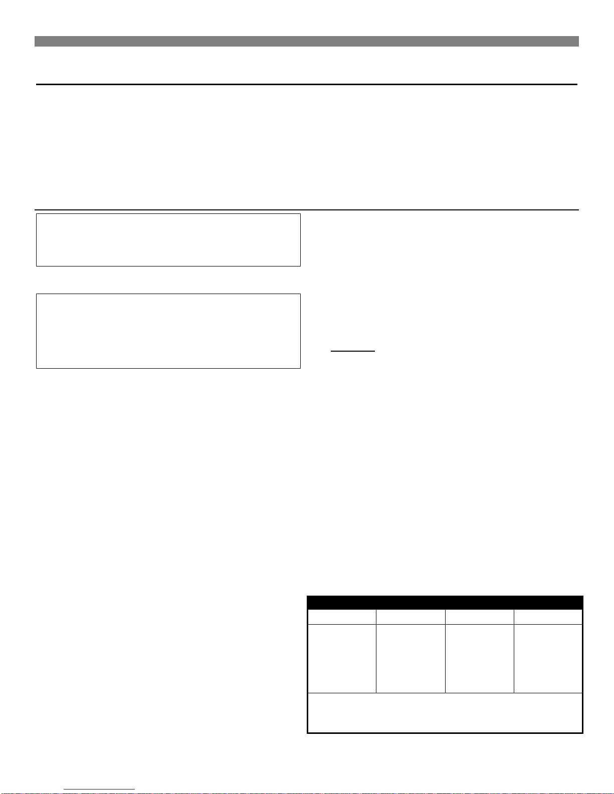
MINIMUM REQUIRED CLEARANCES
MODEL
"A" SIDE
"B" CEILING
"C" REAR
200 SERIES
2"
36"
3"
24” min. Clearance is recommended on side with burner access
Installing Your Heater
The following steps are needed for proper installation and safe
operation of your heater. If you have any doubts as to any
requirements, check with local authorities for local and state
codes affecting the installation.
Obtain professional help where needed.
DO NOT install this heater in a travel trailer, recreational vehicle,
or mobile home.
Locating the Heater
WARNING: Gas burning appliances require air for
combustion and proper venting. Minimum fr esh air
opening of 1 square inch per 1,000 Btu/hr. input
rating must be provided for ventilation.
EXAMPLE: A 30,000 Btu/hr. input unit requires the equivalent of a
30 inch wide window be open 1 inch for safe operation.
WARNING: Danger of property damage, bodily
injury or death. Even when a house meets
requirements for unconfined space with adequate
air infiltration, it is recommended that a fresh air
intake be installed to lessen the possible dangers
from any future changes on the home.
Consider the following points before attempting to install the
heater:
1. In choosing the location for the heater, the following factors
should be considered:
a. Convenience to the gas supply.
b. Arrangement of the rooms or area to be heated.
c. Probable location of the furniture.
d. General appearance.
e. Safe clearance from anything that could catch fire.
f. Ability to properly vent the heater.
2. Locate the heater centrally in the area which it is to heat. The
ideal location is at the source of cold air, which is an outside
wall. If the heater is on an outside wall, the cold air will be
warmed before it moves through the room.
3. Place the heater where the air will circulate freely throughout
the area to be heated. If one heater is intended to heat the
entire house, it is advisable to consider the installation of
grilles immediately below the ceilings to permit circulation of
hot air from room to room. Return air grilles are also
desirable.
4. Be certain the heater is placed where the air is free to
circulate around it. Never install the heater in a wall recess.
The minimum clearance required to any wall or object can be
found on the rating plate located inside the heater control
door on the base plate. We recommend a 24-inch min.
clearance from the burner access door for the ease of lighting
and for observation of pilot and burner flames.
5. The heater must be installed so that the draft hood is in the
same pressure zone as the combustion air.
6. The heater may be placed directly on wood floors. Heavy
pile or shag rugs may restrict normal air flow. Some floor
coverings discolor easily from even low heat. To assure safe
6
IMPORTANT
For satisfactory and trouble-free operation, be sure to:
1. Locate the heater properly within the space to be heated.
2. Provide for adequate combustion air, adequate air circulation
around the cabinet inside the open room and a proper vent
system.
3. Maintain all minimum clearances which apply to your heater.
operation, a metal or wood panel, extending the full depth
and width of the appliance must be placed under the heater.
Optional floor boards are available from Williams.
7. Do not place the heater where curtains, draperies, or any
other material may come into contact with any part of the
heater.
GAS CONTROLS
1. All models are regulated on natural or L.P. Gases. The
regulator is built into the gas control valve.
2. All models are equipped with a 100% pilot safety shutoff and
vent safety shutoff system.
3. CAUTION: Do not connect 115V electrical service line to gas
control valve or wall thermostat.
GAS SUPPLY
For natural gas, the minimum inlet gas supply pressure for the
purpose of input adjustment is 5" water column. The Maximum
inlet gas supply pressure is 7" water column.
For L.P. Gas, the minimum inlet gas supply pressure for the
purpose of input adjustment is 11" water column. The maximum
inlet gas supply pressure is 13" water column.
The gas pressure and input to the burners must not exceed the
rated input and pressure shown on the rating plate. On Natural
Gas, the manifold pressure should be 4 inches water column. The
manifold pressure should be 10 inches water column for L.P. Gas.
Orifice changes may be required to suit the gas supplied.
For heaters located at elevations between sea level and 2,000
feet, the measured input must not be greater than the input shown
on the rating plate of the heater. For elevations above 2,000 feet,
the measured input must not exceed the input of the rating plate
reduced by 4 percent for each 1,000 feet that the heater is above
sea level.
350 SERIES
500 SERIES
650 SERIES
door for ease of lighting and for observation of pilot and burner
flames.
6"
6"
6"
57"
57"
57"
6"
6"
6"
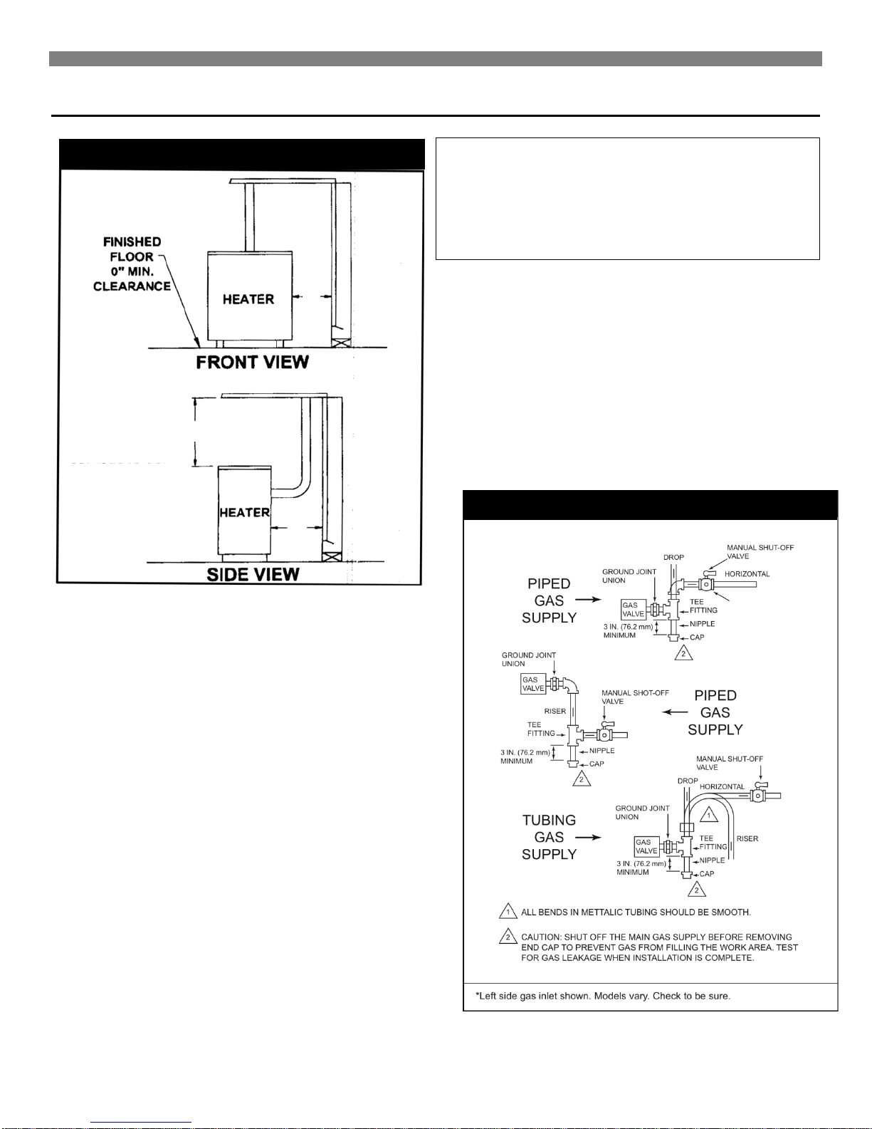
FIGURE 1 Minimum Required Clearances
FIGURE 2 Left Side Gas Inlet
A B C
1/8 IN NPT PLUGGED
HOLE FOR TEST
GUAGE
Installing Your Heater
OPEN IN FRONT TO
OPEN IN FRONT TO
PROVIDE SERVICE,
PROVIDE SERVICE,
ACCESS AND
ACCESS AND
CLEARANCE TO
CLEARANCE TO
COMBUSTIBLES.
COMBUSTIBLES.
WARNING: When connecting field piping, use a
second wrench to keep the heater valve from
turning. Support field piping properly, stress and
over tightening could damage the gas valve and
result in dangerous gas leaks which can cause
dangerous conditions including property damage,
bodily injury, and even death.
4. A drip leg (Figure 2) should be installed to constitute a trap to
catch any condensate that may be in the gas. The drip leg
should be readily accessible for cleaning.
5. The heater must be disconnected from the gas supply system
and from the heaters individual shutoff valve when the system
is tested at a pressure in excess of 1/2 PSI.
6. Check all factory and field pipe joints for gas leaks before and
after lighting the heater. Use a soap solution. Never use a
match or open flame. Correct any leak (s), no matter how
small.
7. Piping supply shall be supported to prevent sagging damage
to the controls and hazardous gas leaks. To prevent freezing
where the supply pipe is exposed to cold air, wrap the pipe or
run it underground.
Note: Minimum fresh air opening is 1 square inch per 1,000
Btu/hr.
GAS PIPING
State and local authorities have established codes regulating the
installation of gas burning equipment. Consult your gas supplier or
gas company for complete information. In the absence of local
codes, all aspects of the installation must comply with the National
Fuel Gas Code ANSI Z223.1. In Canada: Follow the CAN/CGAB149.1(2) Canadian Standard.
1. Use ½-inch pipe or semi-rigid tubing for natural and Liquefied
Petroleum Gases. DO NOT USE FLEXIBLE HOSE.
Appliance connectors of corrugated metal tubing and fittings
that are listed by a nationally recognized testing agency may
be used if accepted by the local code authorities. FOLLOW
THE MANUFACTURER’S INSTALLATION INSTRUCTIONS.
This type of connection may only be installed in the room
where the heater is located.
2. A manual shutoff valv e and uni on m ust b e ins tal led in the gas
supply line just ahead of the connection to the heater. The
manual valve must include a 1/8-inch NPT plugged tapping
accessible for connection of a test gauge.
3. Unions in the gas supply lines should be of the ground joint
type. Compounds used on threaded pipe joints must be
resistant to the action of liquefied petroleum gases.
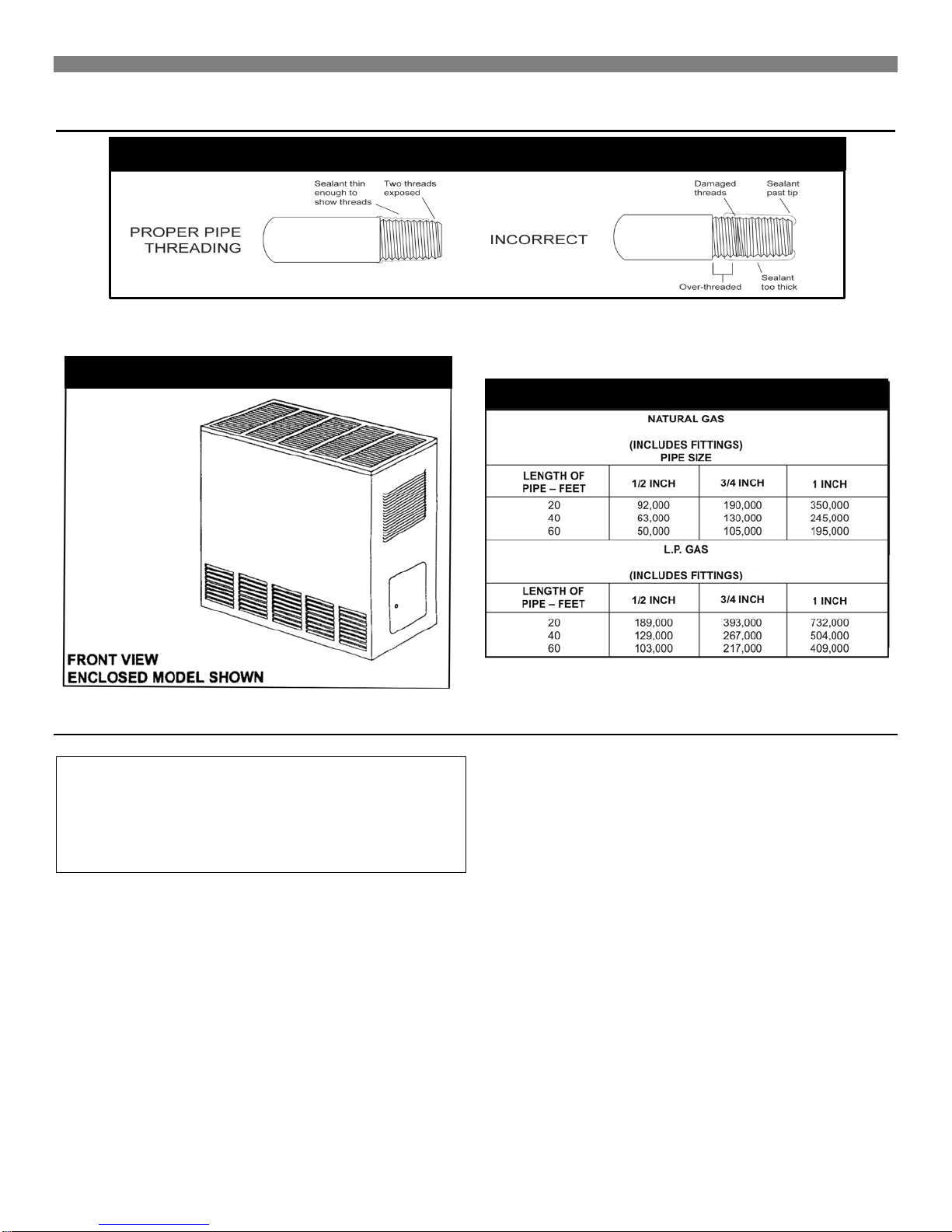
FIGURE 3 Proper Piping Practice
FIGURE 4 Enclosed Model
FIGURE 5 Gas Pipe Sizes
PIPE CAPACITY - Btu/hr.
PIPE CAPACITY - Btu/hr.
Installing Your Heater
IMPORTANT: All piping must comply with local codes and ordinances or with the National Fuel Gas Code (ANSI Z223.1 NFPA No. 54),
whichever applies. (In Canada: CAN/CGA B149).
Combustion & Ventilation Air
WARNING: Danger of property damage, bodily
injury or loss of life. The furnace and any other fuelburning appliances must be provided with enough
fresh air for proper combustion and ventilation of
flue gases. Most homes will require that outside air
be supplied into the heated area.
The high cost of energy for home heating has brought about new
materials and methods used to construct or remodel most current
homes. The improved construction and additional insulation has
reduced the heat loss and made these homes much tighter
around windows and doors so that infiltrated air is minimal. This
creates a problem to supply combustion and ventilation air for
gas-fired or other fuel burning appliances. Any use of appliances
that pull air out of the house (clothes dryers, exhaust fans,
fireplaces, etc.) increases this problem and appliances could be
starving for air.
In addition, these energy measures mean that your home will
retain more water vapor or a higher relative humidity.
High humidity, especially during cold weather, may be damaging
to buildings because condensation forms on windows and inside
walls.
The combination of a tight energy efficient home with the use of
exhaust fans, fireplaces, clothes dryers, and gas appliances result
in more and more air being drawn from the house until fresh air
may be sucked back into the house down a furnace flue or
fireplace chimney. Carbon monoxide can be the result. Carbon
monoxide (CO) is a colorless, odorless gas produced when fuel is
not burned completely or when the flame does not receive
sufficient oxygen. Automobiles, charcoal, wood fires and
improperly vented or air-starved coal, oil and gas furnaces or
other appliances can produce carbon monoxide.
Be aware of these air-starvation signals:
1. Headaches, nausea, dizziness.
2. Excessive humidity shown by heavily frosted windows or a
moist "clammy" sensation.
3. Fireplace smoke fills the room or will not draw.
4. Furnace flue backs up.
8
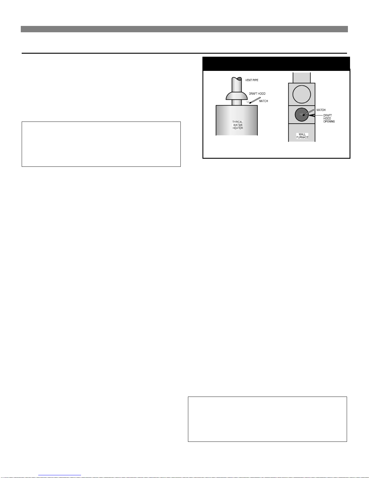
FIGURE 6 Draft Hood Spillage
Installing Your Heater
AIR REQUIREMENTS
The requirements for providing air for combustion and ventilation
are listed in the National Fuel Gas Code NFPA 54/ANSI Z223.1 (in
Canada: CAN/CGA B149). Most homes will require that outside
air be supplied to the heated area by means of ventilation grilles
or ducts connecting directly to the outside or spaces open to the
outdoors such as attic or crawl space. The only exception is when
the furnace area meets the requirements and definitions for an
unconfined space with adequate air infiltration.
WARNING: Danger of property damage, bodily
injury or loss of life. The furnace and any other fuelburning appliances must be provided with enough
fresh air for proper combustion and ventilation of
flue gases. Most homes will require that outside air
be supplied into the heated area.
All air openings and connecting ducts must comply with the
following:
If the furnace is installed in an area with another gas appliance(s),
the total input rating of all appliances must be considered when
determining the free area requirements for combustion and
ventilation air openings.
Ducts must have the same cross-sectional area as the free area
of the openings to which they connect. The minimum dimension
of rectangular air ducts must not be less than 3-inches in length or
height.
LOUVERS / GRILLES AND SCREENS COVERING
FREE AREA OPENINGS
If a screen is used to cover the opening(s), it must not be smaller
than 1/4-inch mesh. Use the free area of a louver or grille to
determine the size opening required to provide the free area
specified. If the free area is not known, assume a 20% free area
for wood and a 60% free area for metal louvers or grilles.
EXAMPLE 1
FURNACE LOCATED IN UNCONFINED SPACE.
*
An unconfined space must have a volume of a minimum 50 cubic
feet per 1000 Btu/hr. of total of all appliances in area. Adjoining
rooms may be included only if there are no doors between the
rooms, or if special provisions are made such as ventilation grilles
installed between connecting rooms.
Page 10, figure 8 shows the minimum area in square feet' based
on 8 foot ceiling heights, required for different Btu/hr. input ratings.
A. If your furnace is in an open area (unconfined space*) the
air that leaks through the cracks around doors and windows
may be enough for combustion and ventilation air. The doors
should not fit tight. The cracks around windows should not
be caulked or weather stripped.
To determine if infiltration air is adequate, perform following
checks:
1. Close all doors and windows. If you have a fireplace,
start a fire and wait until flames are burning vigorously.
*
2. Turn on all exhausting devices, such as:
kitchen and bathroom exhaust fans
dryers (gas and electric)
3. Turn on all vented gas appliances, such as:
heating equipment (includes any room heaters)
water heater
4. Wait ten (10) minutes for drafts to stabilize.
5. Check for draft hood spillage at each appliance. (Hold a
lighted match 2 inches from draft opening. See Fig. 6.)
B. No Spillage
If the match flame pulls toward draft hood - this indicates
sufficient infiltration air:
1. Return exhausting devices and appliances to the
condition you found them.
C. Draft Hood Spills
If there is spillage at a draft hood (match goes out or flame
wavers away from draft hood):
1. Check for plugged flue connectors and chimneys. Check
and repair, stoppage and test again.
2. If you have a fireplace, open a window or door near the
fireplace and then check for spillage.
a) If spillage stops, do not use the fireplace without a
nearby window or door open until you can supply
fresh air by a permanent duct.
3. If you have kitchen and bathroom exhaust fans, turn
them off and check for spillage.
a) If spillage stops, do not use exhaust fans until you
can supply fresh air by a permanent duct.
WARNING: Danger of property damage, bodily
injury or loss of life. Draft hood spillage, with
unobstructed vents, indicates that additional air
must be brought into the structure from outside.
Keep a window open (minimum 2 inches) near the
appliance until a permanent air duct is installed.
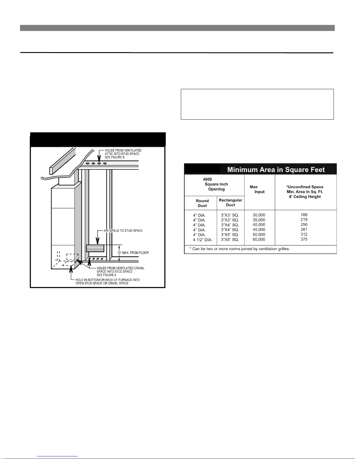
FIGURE 7 Fresh Air duct
Btu/hr. Per
FIGURE 8
Installing Your Heater
4. Spillage means air starvation and a fresh air duct or air
intakes must be installed to provide air directly to the
furnace or other gas appliance.
D. If spillage exists or when the furnace is in a building of tight
construction where the windows and doors are weatherstripped, air for combustion and ventilation must be obtained
from outdoors or space open to the outdoors.
Provide an opening(s) having a total free area of 1-square inch
per 4000 Btu/hr. for the total of all appliances. The required area
is shown on page 11, Fig. 11.
within 12 inches of the bottom of the room connecting directly to
unconfined space. Each opening must have a free area of at least
100 square inches or 1 square inch per 1000 Btu/hr. combined
input of appliances in one room if combined input exceeds
100,000 Btu/hr.
WARNING: Danger of property damage, bodily
injury or loss of life. The adjoining unconfined
space must have adequate air infiltration as def ined
in example 1.
FOR EXAMPLE: Your furnace is rated at 50,000 Btu/hr. The water
heater is rated at 30,000 Btu/hr. The total is 80,000 Btu/hr. You
need two grilles, each with 100 square inches of free opening.
Metal grilles have about 60% free area, so you need two metal
grilles each with 160 square inches of louvered area.
Fig. 7 shows a typical duct going into ventilated crawl space
or attic.
1. Duct must terminate at a point not more than 1 foot
above the floor.
2. Duct size must be at least 1 inch of free area for each
4000 Btu/hr. of input of all appl ianc es in area.
EXAMPLE 2.
FURNACE LOCATED IN CONFINED SPACE.
If furnace is installed in a confined space, it must be provided with
free air for proper combustion and ventilation of flue gases by one
of the following methods.
A. All Air From Inside Building:
If the confined space adjoins an unconfined, provide two
permanent openings, one within 12 inches of the top and one
Refer to figure as shown on Page 11, Fig. 9, which shows grille
installation. Using the previous example, the two connecting
rooms plus the closet must equal at least 500 sq. feet to handle
the combined input 50,000 plus 30,000.
B. All Air From Outdoors:
If confined space doesn't adjoin an unconfined space then air
must be provided from outdoors or spaces open to outdoors such
as attic or crawl space.
Provide two permanent openings, one within 12 inches of top, one
within 12 inches of bottom of room connecting directly, or by using
ducts, with the outdoors or areas open to outdoors.
If opening connects directly to, or within vertical ducts, the free
area of each opening must be at least 1 square inch per 4000
Btu/hr. combined input of appliances in area.
If horizontal ducts are used, the free area of each opening must
be at least 1 square inch per 2000 Btu/hr. combined input of
appliances in area.
10
 Loading...