

Page 1
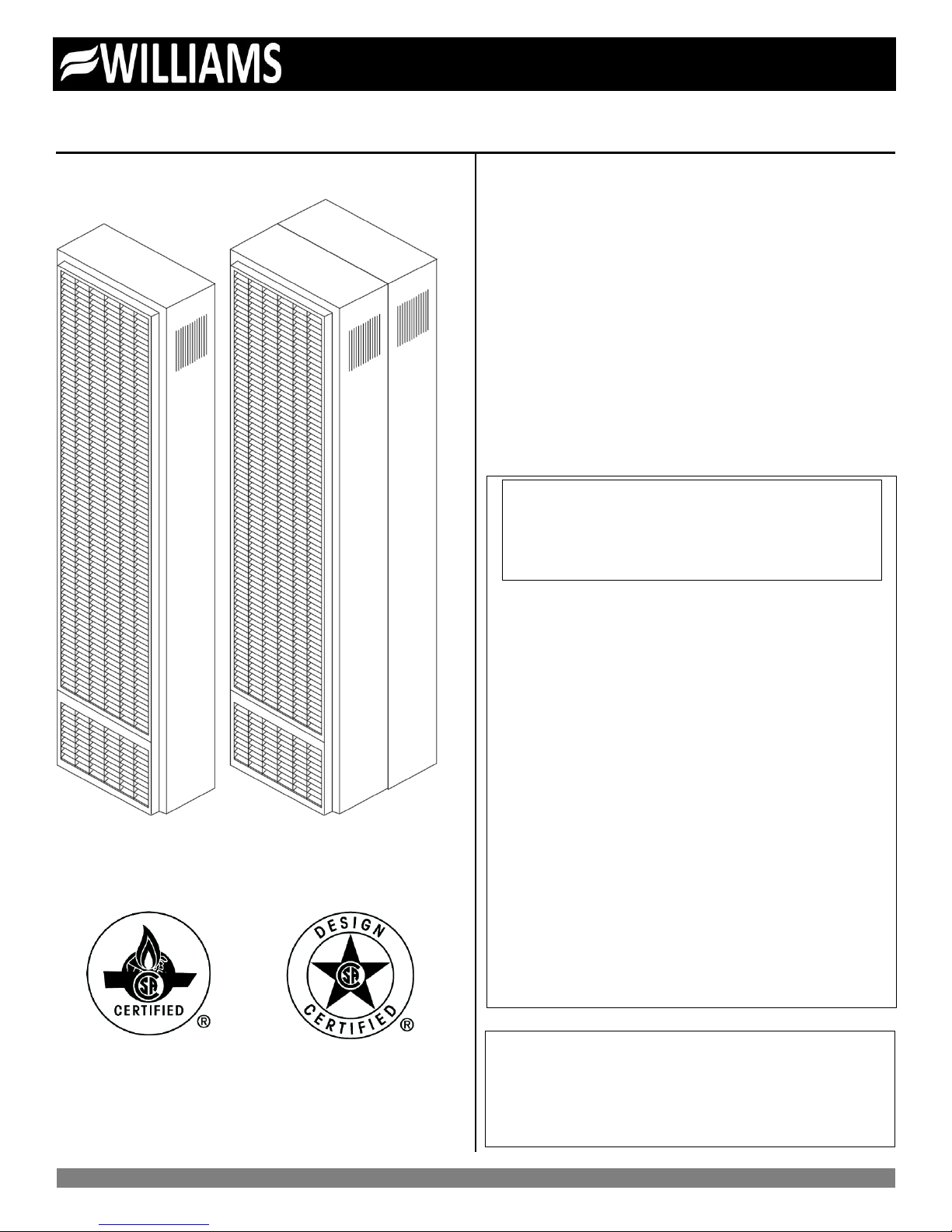
50,000
Btu/hr. Model
25,000 and 35,000
Btu/hr. Model
the gas supplier.
WARNING: If the information in these
instructions is not followed exactly, a fire or
explosion may result causing property
damage, personal injury or loss of life.
Owner’s Manual Save this manual for future reference.
Top-Vent Gravity Wall
Furnace
Model Numbers:
2509622; 2539622; 2559622; 3509622; 3539622; 3559622;
5009622; 5039622; 5059622
FOR USE WITH NATURAL GAS ONLY
Model Numbers:
2509621; 2539621; 2559621; 3509621; 3539621; 3559621;
5009621; 5039621; 5059621
FOR USE WITH PROPANE GAS ONLY
READ THIS OWNER’S MANUAL CAREFULLY BEFORE YOU
INSTALL YOUR NEW WILLIAMS WALL FURNACE.
Do not store or use gasoline or other
flammable vapors and liquids in the vicinity
of this or any other appliance.
WHAT TO DO IF YOU SMELL GAS:
Open all windows.
Do not try to light any appliance.
Do not touch any electrical switch; do not
use any phone or cell phone in your
building.
Extinguish any open flame.
Immediately call your gas supplier from
a neighbor’s phone. Follow the gas
supplier’s instructions.
If you cannot reach the gas supplier,
call the fire department.
Installation and service must be performed
by a qualified installer, service agency or
Williams Furnace Co. 250 West Laurel Street Colton, California 92324 U.S.A.
WARNING: Improper installation, adjustment,
alteration, service or maintenance can cause injury
or property damage. Refer to this manual. For
assistance or for additional information consult a
qualified installer, service agency or the gas
supplier.
Page 2
Warranty & Installation Record – 2
2
Warranty
The manufacturer, Williams Furnace Co., warrants this wall furnace or heater to the original purchaser under the following conditions:
LIMITED ONE-YEAR WARRANTY
1. Any part thereof which proves to be defective in material or workmanship within one year from date of original purchase for use will be replaced at the Manufacturer’s
option, FOB to its factory.
2. No liability is assumed by the Manufacturer for removal or installation labor costs, nor for freight or delivery charges.
LIMITED EXTENDED WARRANTY
1. In addition to the above limited one-year warranty on the complete unit, any combustion chamber which burns out or rusts under normal installation, use and service
conditions during a period of nine years following expiration of the one-year warranty period will be exchanged for a like or functionally similar part.
2. No liability is assumed by the Manufacturer for removal or installation labor costs, nor for freight or delivery charges.
LIMITATIONS
1. THIS LIMITED WARRANTY IS THE ONLY WARRANTY MADE BY THE MANUFACTURER, IMPLIED WARRANTIES OF MERCHANTABILITY OR FITNESS FOR ANY
PARTICULAR PURPOSE ARE LIMITED TO THE SAME ONE YEAR TERM AS THE EXPRESS WARRANTY. UNDER NO CIRCUMSTANCES SHALL THE
MANUFACTURER BE LIABLE FOR INCIDENTAL, CONSEQUENTIAL, SPECIAL OR CONTINGENT DAMAGES OR EXPENSES ARISING DIRECTLY OR INDIRECTLY
FROM ANY DEFECT IN THE PRODUCT OR ANY COMPONENT OR FROM THE USE THEREOF. THE REMEDIES SET FORTH HEREIN ARE THE EXCLUSIVE
REMEDIES AVAILABLE TO THE USER AND ARE IN LIEU OF ALL OTHER REMEDIES.
Some states do not allow limitation on how long an implied warranty lasts, and some states do not allow the exclusion or limitation of incidental or consequential
damages, so the above limitations or exclusions may not apply to you.
2. This warranty does not include any charge for labor or installation.
3. This warranty does not extend to painted surfaces or to damage or defects resulting from accident, alteration, misuses or abuse or improper installation.
4. This warranty does not cover claims which do not involve defective workmanship or materials.
DUTIES OF THE CONSUMER
1. The heating equipment must be installed by a qualified installer and operated in accordance with the installation and homeowner’s instructions furnished with the
equipment.
2. Any travel, diagnostic costs, service labor, and labor to repair the defective unit will be the responsibility of the owner.
3. A bill of sale, cancelled check, payment record or permit should be kept to verify purchase date to establish the warranty period.
4. Have the installer enter the requested information in the space below.
GENERAL
1. The manufacturer neither assumes nor authorizes any person to assume for it any other obligation or liability in connection with said equipment.
2. Service under this warranty should be obtained by contacting your dealer. Provide the dealer with the model number, serial number, and purchase date verification.
3. If, within a reasonable time after contacting your dealer, satisfactory service has not been received, contact: Customer Service Department, 250 West Laurel Street,
Colton, CA 92324 for assistance.
4. THIS WARRANTY GIVES YOU SPECIFIC LEGAL RIGHTS AND YOU MAY ALSO HAVE OTHER RIGHTS WHICH VARY FROM STATE TO STATE.
Installation Record
Model No. ______________________________________________________________ Serial No. ___________________________
Original Purchaser ____________________________________________________________________________________________
Address ____________________________________________________________________________________________________
City and State ___________________________________________________________ Zip ________________________________
Dealer _____________________________________________________________________________________________________
Address ____________________________________________________________________________________________________
City and State ___________________________________________________________ Zip ________________________________
Installation Date _______________ Name ________________________________ Signature_________________________________
(Dealer or authorized representative who certifies that this appliance is installed in accordance with Manufacturer’s instructions and local codes.)
Page 3
Contents
Your Williams Warranty ................................................................. 2
Installation Record ......................................................................... 2
Table of Contents .......................................................................... 3
Safety Rules .................................................................................. 4
Introduction .................................................................................... 5
Basic Materials Needed................................................................. 5
Basic Tools Needed ...................................................................... 5
Optional Accessories ..................................................................... 5
Installing Your Wall Furnace .......................................................... 6
Locating Wall Furnace and Thermostat ..................................... 6-7
Combustion & Ventilation Air ..................................................... 7-9
Installation
Recessed Mount Installation ........................................ 10-11
Surface Mount Installation ........................................... 12-13
Vent Installation ................................................................. 14
Attaching Your Furnace ......................................................... 15-16
Gas Supply and Piping .......................................................... 16-18
Front Panel Installation ................................................................ 18
Thermostat Installation ................................................................ 19
Start Up Procedure ................................................................ 20-21
Stay Safe………………………………………………………….22-23
Operating Your Furnace………………………………………...22-23
How to Care for Your Furnace ……………………….………..24-25
Installing Your Blower Accessory………………………………25-26
Blower Accessory Replacement Parts....….…………………..27-28
Installing Your Motorized Rear Outlet Accessory...….............29-30
Motorized Rear Outlet Replacement Parts...……………....…31-32
Furnace Replacement Parts …………………………..……….32-37
Troubleshooting Chart...…..…………………………………….38-39
Service Hints………………………………………………...............40
Quick Reference: Here’s how to…
Installing Your Furnace ............................................................ 6-20
Recessed Mount, Surface Mount, and Vent Installation are
explained starting on page 6.
Operating Your Furnace ........................................................ 22-23
Igniting your furnace for the first time.
Caring for Your Furnace ........................................................ 24-25
Learn how to keep your new Williams Furnace operating.
Page 4
4
WARNING: Do not install any of these furnaces (Natural or
L.P. Gas) in mobile homes, trailers or recreational vehicles.
Safety Rules
WARNING: Read these rules and the instructions
carefully. Failure to follow these rules and
instructions could cause a malfunction of the
furnace. This could result in death, serious bodily
injury and/or property damage.
INSTALLATION MUST CONFORM TO LOCAL CODES. IN THE
ABSENCE OF LOCAL CODES, INSTALLATION MUST
CONFORM TO THE NATIONAL FUEL GAS CODE, ANSI Z223.1.
THE APPLIANCE, WHEN INSTALLED MUST BE
ELECTRICALLY CONNECTED AND GROUNDED IN
ACCORDANCE WITH LOCAL CODES OR, IN THE ABSENCE
OF LOCAL CODES, WITH THE CURRENT NATIONAL
ELECTRICAL CODE ANSI/NFPA NO. 70.
8. Vent the furnace directly to the outdoors, so that harmful
gases will not collect inside the building. Follow the venting
instructions for your type installation exactly. Use only the
type and size of vent pipe and fittings specified.
9. Provide for adequate combustion and ventilation air. See
page 7. The flow of this air to the furnace must not be
blocked.
10. NEVER vent flue gases into another room, a fireplace or
any space inside a building. This could cause property
damage, bodily injury or death.
11. NEVER test for gas leaks with an open flame. Use a soap
solution to check all gas connections. This will avoid the
possibility of fire or explosions.
IN CANADA: Installation must conform to local
codes or, in the absence of local codes, the current
CAN/CGA B149 Installation code.
The appliance, when installed, must be grounded in
accordance with local codes, with the current CSA
C22.1 Canadian Electrical Code.
Reference is made in this manual regarding gas
type as L.P.G. Be advised that L.P.G. is not
available in Canada; refer to Propane/L.P. Gas.
WARNING: Do not use this furnace if any part has
been under water. Immediately call a qualified
service technician to inspect the furnace and to
replace any part of the control system and any gas
control which has been under water.
1. Use only manufacturer’s replacement parts. Use of any
other parts could cause injury or death.
2. DO NOT install the furnace where it could be isolated by
closing doors to the heated space.
3. DO NOT install these furnaces in a travel trailer, recreational
vehicle or mobile home.
4. MAINTAIN all clearances specified in section “Locating Wall
Furnace and Thermostat” and “Vent Installation.”
5. BE SURE the furnace is for type of gas being used. Check
the nameplate by the gas valve in the lower cabinet. Do not
change it to use other gases without the proper
manufacturer’s gas conversion kit.
6. For natural gas, the minimum inlet gas supply pressure for
the purpose of input adjustment is 5” water column. The
maximum inlet gas supply pressure is 7” water column. For
L.P. gas, the minimum inlet gas supply pressure for the
purpose of input adjustment is 11” water column. The
maximum inlet gas supply pressure is 13” water column.
7. Any safety screen, guard or parts removed for servicing this
appliance must be replaced prior to operating the appliance
to avoid property damage, bodily injury or death.
12. , ALLOW furnace to cool before servicing. Always shut off
electricity and gas to furnace when working on it. This will
prevent any electrical shocks or burns.
13. DUE TO HIGH TEMPERATURES, locate the furnace out of
traffic and away from furniture and draperies.
14. ALERT children and adults to the hazards of high surface
temperatures and warn them to keep away to avoid burns
or clothing ignition.
15. CAREFULLY supervise young children when they are in the
same room with the furnace.
16. DO NOT place clothing or other flammable material on or
near furnace.
17. INSTALLATION and REPAIR must be done by a qualified
service person. The appliance should be inspected before
use and at least annually by a professional service person.
More frequent cleaning may be required due to excessive
lint from carpeting, bedding material, etc. It is imperative
that control compartments, burners and circulating air
passages be kept clean.
18. BEFORE INSTALLING: To avoid electrical shock, turn off
electrical circuits that pass through the wall where you are
going to install the furnace.
19. BE AWARE of good safety practices by wearing personal
protective equipment such as gloves and safety glasses to
avoid being injured by sharp metal edges in or around the
furnace while cutting or drilling holes in wood and/or sheet
metal.
20. CAUTION: Label all wires prior to disconnection when
servicing controls.
21. DO NOT store or use gasoline or other flammable liquids or
vapors near the furnace.
Page 5
Introduction – 5
Introduction
The following steps are all needed for proper installation and safe operation of your furnace. If you have any doubts as to any
requirements, check with local authorities. Obtain professional help where needed. All of the checks and adjustments in the Start-Up
Procedures are vital to the proper and safe operation of the furnace. Please read the instructions before you install and use your
furnace. This will help you obtain the full value from this furnace. It could also help you avoid needless service costs if the answer to
the problem is found within this instruction manual.
Always consult your local heating or plumbing inspector, building department or gas utility company regarding regulations codes or
ordinances which apply to the installation of a vented wall furnace.
Check the furnace nameplate, located in the burner compartment, to make sure your furnace is equipped to operate on the type of gas
available (either natural or L.P. gas). DO NOT convert the furnace from natural gas to L.P. gas or from L.P. gas to natural gas without
the proper manufacturer’s gas conversion kit.
Combustion air is drawn in from the room where the furnace is located and is vented out of the top of the furnace vertically through vent
piping in the stud space to a roof vent top. Vent material is not supplied with the furnace.
This furnace is equipped with a vent safety shutoff system designed to protect against improper venting of combustion products.
Operation of this wall furnace when not connected to a properly installed and maintained venting system or tampering with the vent
safety shutoff system can result in carbon monoxide (CO) poisoning and possible death.
The efficiency rating of this furnace is a product thermal efficiency rating determined under continuous operating conditions and was
determined independent of any installed system.
Basic Materials Needed
Pipe and fittings to make gas connections to the furnace.
Vertical venting materials. See page 14, Figure 8.
Basic Tools Needed
Hand drill or properly grounded electric drill
Expansion bit 1/2” to 1-5/8” or 1/2” and 1-1/2” blade bits
1/8” and 3/16” drill bit (metal)
6 ft. folding rule or tape measure
Screwdriver (medium blade)
Screwdriver (Phillips head)
Pliers (wire cutting)
Helpful Installation Information
The following booklets will help you in making the installation:
ANSI/NFPA 70, or current edition “National Electrical Code”. In Canada: CSA C22.1 Canadian Electrical Code.
American National Standard Z223.1 or current edition of the “National Fuel Gas Code.”
Obtain from the American National Standard Institute, Inc., 1430 Broadway, New York, NY 10018. In Canada, CAN/CGA B149.
Optional Accessories
Blower Accessories 2901, 2907 - May be used on all models and mounts on top of a furnace. This blower increases circulation of
warm air through the heated space. A 115V outlet adjacent to the furnace is required.
Trim Strip Kit 4701 - Provides a finished edge for sides of the wall furnace.
Free Standing Accessory 4901 - May be used with single-sided models. This accessory allows the furnace to be mounted on the
surface of a wall.
Vent Adapter Kit 9902, 9910 - Optional vent adapter, typically used when the furnace is vented into a properly lined chimney.
Rear Outlet Registers 6901, 6919, 6920 - May be used with single-sided models when recessed into a standard 2x4 inch interior stud
partition. This accessory directs some of the heated air into the room opposite the one in which the furnace is installed.
Oval B/W Vent Kit 9901 - This U.L. listed B/W vent kit contains four feet of oval, double-walled vent pipe, plate spacers and base or
hold-down plate that starts the venting from the top of furnace. See Vent Installation on page 14 for additional items you will need.
Plaster Ground Kit 6905 - Used for 6901 or 6919 Rear Outlet Registers.
Gas Conversion Kits - See page 16.
Pipe Joint Compound resistant to L.P. Gases.
Electrical wiring supplies as needed. Minimum wire size is #14
gauge copper.
Hammer
Stud Locator or small finishing nails
Tin Snips
8” adjustable wrench
12” adjustable wrench
Two, 10” or 12” pipe wrenches
Gloves and safety glasses
Page 6
6
Installing Your Furnace
The following steps are needed for proper installation and safe
operation of your furnace. If you have any doubts as to any
requirements, obtain professional help. Remember to ALWAYS
consult your local heating or plumbing inspector, building
department or gas utility company regarding regulations, codes,
or ordinances which apply to the installation and location of a
vented wall furnace.
IMPORTANT
2. Install the furnace in accordance with local codes or
ordinances and instructions provided. In the absence of
local codes or ordinances, install the furnace to conform
with the current edition of the National Fuel Gas Code,
NFPA 54, ANSI Z223.1/Canadian Installation Code,
CAN/CGA B149.
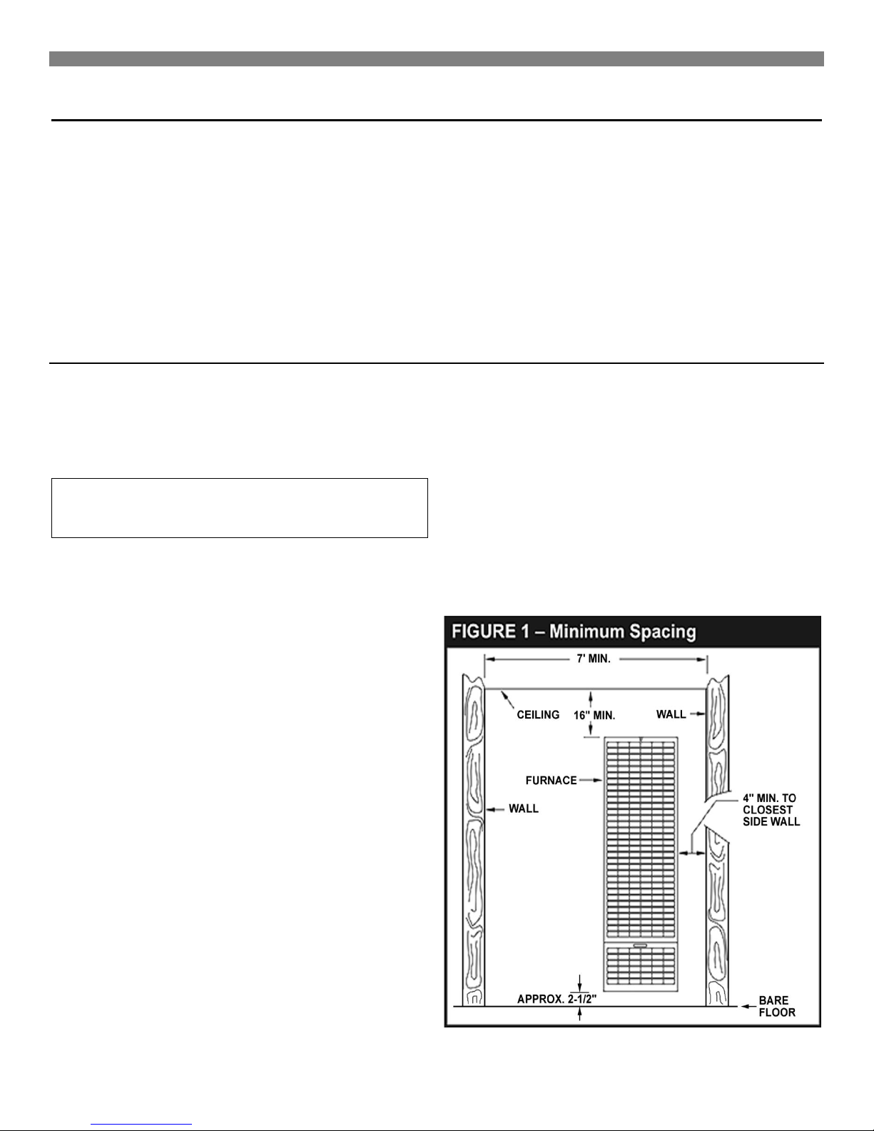
3. Maintain minimum clearances: Floor 2½-inches, ceiling 16inches, side wall 4-inches.
For satisfactory and trouble-free operation, be sure to:
1. Locate the furnace properly within the space to be heated.
Locating Wall Furnace & Thermostat
The furnace is installed between 2x4 inch wall studs spaced on
16-inch centers or a stud space that can be framed in to 16-
inches.
Consider the following points before attempting to install the
furnace:
CAUTION: Do not make cutouts in the wall or
ceiling before checking in the attic for ceiling joist
locations and proposed venting.
1. Locate the furnace near the center of the space to be
heated for good air circulation. Do not put it behind a door
or draperies. Do not install the furnace where it could be
isolated by closing doors to the heated space. Do not
locate the furnace where a door could swing over the front
panel or where circulation could be retarded by furniture or
cabinets.
2. Check the minimum spacing needs as shown in Figure 1.
3. The top of the furnace must be at least 16-inches from the
ceiling.
4. When the furnace is properly installed with legs resting on
the floor plate, it sets the dimension from the face panel to
the bare floor. (Approximately 2½-inches depending on the
thickness of floor plate).
5. A protective barrier (metal or wood), cut to match the width
and depth of the furnace, should be used to cover over
any floor coverings such as carpet or vinyl under the
furnace. At no time should the dimension from the bottom
of the face panel to the protective barrier be less than 1½inches.
6. In the space to be heated, the side of the furnace may be
as close as 4-inches to an intersecting wall. The recessed
portion may have 0-inches clearance to combustible
material.
7. Select a location that will provide adequate accessibility
clearance for servicing and proper operation.
4. Provide enough combustion and ventilation air.
8. After picking a location, inspect the wall, floor, attic and
roof areas. Make sure there are no pipes, wiring, bracing,
etc., that will interfere with furnace or vent installation. If
required, move them or pick a new installation location.
9. Be sure that gas piping and electrical wiring can be
brought to the location. Electrical wiring is required for
optional blower accessory.
10. If installing the thermostat on the wall, locate the
thermostat approximately 5-feet above the floor on an
inside wall where it will sense the average room
temperature.
Page 7
Locating Wall Furnace & Thermostat (continued)
WARNING: Danger of property damage, bodily injury or loss of life. Even when a house meets
requirements for unconfined space with adequate air infiltration, it is recommended that a fresh air intake be
installed to lessen the possible dangers from any future changes on the home
Installing Your Furnace
Locating Wall Furnace & Thermostat (continued)
The thermostat should be sensing average room temperature;
avoid the following:
HOT SPOTS: COLD SPOTS:
Concealed pipes or ducts Concealed pipes or ducts
Fireplaces Stairwells – drafts
Registers Doors – drafts
TV sets Unheated rooms on
Radios other side of wall
Lamps
Direct sunlight DEAD SPOTS
Kitchen Behind doors
Corners and alcoves
Combustion & Ventilation Air
WARNING: Danger of property damage, bodily
injury or loss of life. The furnace and any other fuelburning appliances must be provided with enough
fresh air for proper combustion and ventilation of
flue gases. Most homes will require that outside air
be supplied into the heated area.
The high cost of energy for home heating has brought about new
materials and methods used to construct or remodel most current
homes. The improved construction and additional insulation has
reduced the heat loss and made these homes much tighter
around windows and doors so that infiltrated air is minimal. This
creates a problem to supply combustion and ventilation air for
gas-fired or other fuel burning appliances. Any use of appliances
that pull air out of the house (clothes dryers, exhaust fans,
fireplaces, etc.) increases this problem and appliances could be
starving for air.
The combination of a tight energy efficient home with the use of
exhaust fans, fireplaces, clothes dryers, and gas appliances result
in more and more air being drawn from the house until fresh air
may be sucked back into the house down a furnace flue or
fireplace chimney. Carbon monoxide can be the result. Carbon
monoxide (CO) is a colorless, odorless gas produced when fuel is
not burned completely or when the flame does not receive
sufficient oxygen. Automobiles, charcoal, wood fires and
improperly vented or air-starved coal, oil and gas furnaces or
other appliances can produce carbon monoxide.
Do not install furnace in the same room or near a wood solid fuel
burning fireplace.
After picking a location that meets the requirements, check the
walls, attic and roof to make sure there are no obstructions such
as pipes, electrical wiring, etc., which could interfere with the
installation of the furnace or vent pipe. If required, move them or
pick a new location.
WARNING: Danger of property damage, bodily
injury or loss of life. Do not install the furnace in any
area where oxygen is in use.
BE AWARE OF THESE AIR-STARVATION SIGNALS:
1. Headaches, nausea, dizziness.
2. Excessive humidity shown by heavily frosted windows or a
moist "clammy" sensation.
3. Fireplace smoke fills the room or will not draw.
4. Furnace flue backs up.
AIR REQUIREMENTS
The requirements for providing air for combustion and ventilation
are listed in the National Fuel Gas Code NFPA 54/ANSI Z223.1 (in
Canada: CAN/CGA B149). Most homes will require that outside
air be supplied to the heated area by means of ventilation grilles
or ducts connecting directly to the outside or spaces open to the
outdoors such as attic or crawl space. The only exception is when
the heated area meets the requirements and definitions for an
unconfined space with adequate air infiltration.
All air openings and connecting ducts must comply with the
following:
If the furnace is installed in an area with another gas appliance(s),
the total input rating of all appliances must be considered when
determining the free area requirements for combustion and
ventilation air openings.
Ducts must have the same cross-sectional area as the free area
of the openings to which they connect. The minimum dimension
of rectangular air ducts must not be less than 3-inches in length or
height.
Page 8
8
Hole Placement - Example
Square inches
of Opening
Installing Your Furnace
Combustion & Ventilation Air (continued)
LOUVERS / GRILLES AND SCREENS COVERING
FREE AREA OPENINGS
If a screen is used to cover the opening(s), it must not be smaller
than 1/4-inch mesh. Use the free area of a louver or grille to
determine the size opening required to provide the free area
specified. If the free area is not known, assume a 20% free area
for wood and a 60% free area for metal louvers or grilles.
INFILTRATION AIR
If your furnace is in an open area (unconfined space), the air that
leaks through the cracks around doors and windows may be
enough for combustion and ventilation air. The doors should not
fit tightly. The cracks around windows should not be caulked or
weather stripped.
Spillage means air starvation. A fresh air duct or air intake
opening must be installed to provide air directly to the furnace or
other gas appliances.
If spillage exists or when the furnace is in a building of tight
construction where the windows and doors are weather stripped,
air for combustion and ventilation must be obtained from outdoors
or space open to the outdoors.
B. Draft Hood Spills
If there is spillage at a draft hood (match goes out or flame wavers
away from draft hood), check for plugged flue connectors and
chimneys. Repair blockage and test again.
If you have a fireplace, open a window or door near the fireplace
and then check for spillage. If spillage stops, do not use the
fireplace without a nearby window or door open until you can
supply fresh air by a permanent duct.
If you have kitchen and bathroom exhaust fans, turn them off and
check for spillage. If spillage stops, do not use exhaust fans
(circuit breakers for fans should be turned off) until you can supply
fresh air by a permanent duct.
Provide opening(s) having a total free area of one-square-inch per
4,000 Btu/hr. of the total combined input ratings for all appliances
in the area. The required free area is shown in Figure 3. This
fresh air opening or duct must terminate at a point not more than
one-foot above the floor. It must have at least one-square inch of
free area for each 4,000 Btu/hr. of input of all appliances in area.
To determine if infiltration air is adequate, perform the following
checks:
1. Close all doors and windows. If you have a fireplace, start a
fire and wait until flames are burning vigorously.
2. Turn on all exhausting devices, i.e., kitchen and bathroom
exhaust fans; water heaters (gas and electric).
3. Turn on all vented gas appliances, i.e., heating equipment
(includes any room heaters), water heaters.
4. Wait ten (10) minutes for drafts to settle.
5. Check for draft hood spillage at each appliance. Hold a lit
match two-inches from the draft opening. (Figure 2).
A. No Spillage
If the match flame pulls toward draft hood, this indicates sufficient
infiltration air. Return exhausting devices and appliances to the
condition you found them.
Page 9
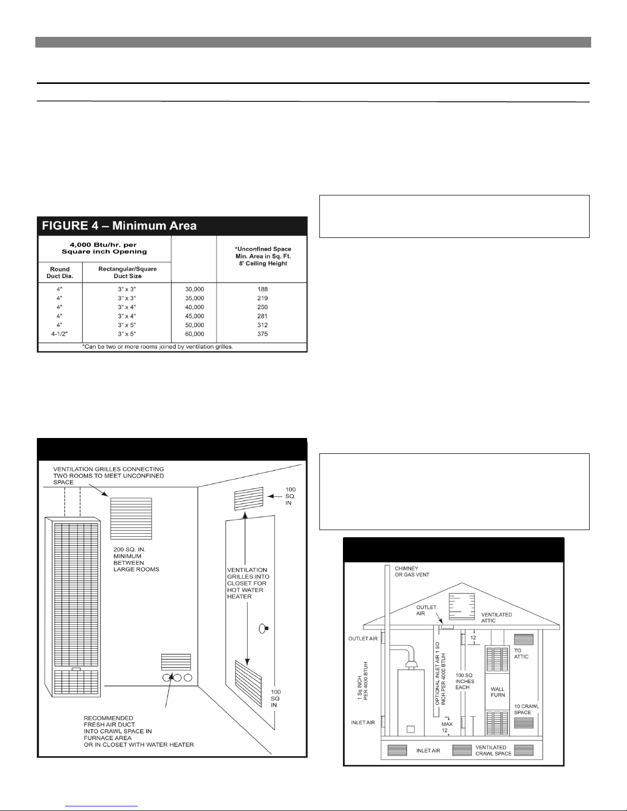
Examples of Grille Placement
Examples of Air Inlets and Outlets
Max.
Installing Your Furnace
Combustion & Ventilation Air (continued)
FURNACE LOCATED IN UNCONFINED SPACE
An unconfined space must have a volume of a minimum 50 cubic
feet per 1,000 Btu/hr. of the total combined input of all appliances
in the area. Adjoining rooms may be included only if there are no
doors between the rooms or if special provisions are made such
as ventilation grilles installed between connecting rooms. Figure
4 outlines the minimum area in square feet, based on 8-foot
ceiling heights for various Btu/hr. input ratings.
Btu/hr.
Input
FURNACE LOCATED IN CONFINED SPACE
If a furnace is installed in a confined space, it must be provided
with free air for proper combustion and ventilation of flue gases by
one of the following methods:
A. Air From Inside the Building
If the confined space adjoins an unconfined space, provide two
permanent openings. One within 12-inches of the top and another
within 12-inches of the bottom of the room directly connected to
the unconfined space. Each opening must have a free area of at
least 100-square inches or 1-square inch per 1,000 Btu/hr. of
input for all appliances combined.
WARNING: Danger of property damage, bodily
injury or death. The adjoining unconfined space
must have adequate air infiltration.
B. Air From Outdoors
If confined space does not adjoin an unconfined space, then air
must be provided from outdoors or spaces open to the outdoors
such as an attic or crawl spaces.
Openings for inlet or outlet air should NOT be made into an attic
area if the attic is equipped with a thermostat controlled power
vent.
Provide two permanent openings, one within 12-inches of the top
and bottom of the room connecting directly to, or by using ducts,
with the outdoors or areas open to fresh air.
If the opening connects directly to, or with vertical ducts, the free
area of each opening must be at least 1-square inch per 4,000
Btu/hr. of the combined input of all appliances in the area.
If horizontal ducts are used, the free area of each opening must
be at least 1-square inch per 2,000 Btu/hr. of the combined input
of all appliances in the area.
WARNING: Danger of illness, bodily injury or
death. Draft hood spillage, with unobstructed vents,
indicates that additional air must be brought into the
structure from the outside. Keep a window open
(minimum 2-inches) near the appliance until a
permanent air duct is installed.
Page 10
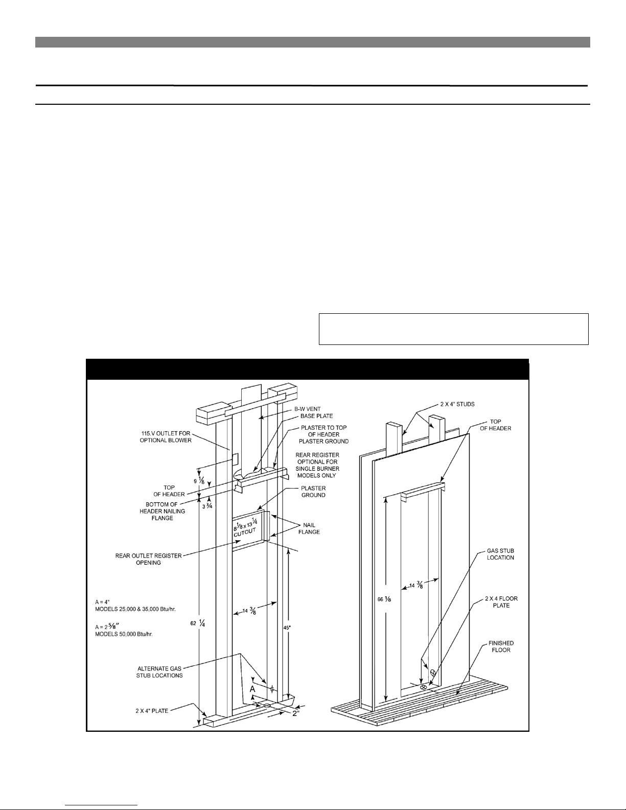
10
FIGURE 5 – Recessed Wall Mount Installation
Installing Your Furnace
Recessed Wall Mount Installation
On models 2509621, 2539621, 2559621, 2509622, 2539622,
2559622, 3509621, 3539621, 3559621, 3509622, 3539622, and
3559622, the maximum recess depth from rear of furnace forward
is 4½ inches.
FIND THE STUDS AND CEILING JOINTS
Use a stud locator or small finishing nails. Repeatedly drive and
remove a nail into the wall in the area of the stud until it is located.
Then find the inside edge of the stud. Leave the nail at this
location.
The other stud should be about 14½-inches from the one found.
Drive finishing nails on the inside of this stud. Draw wall cutout to
required size as shown in Figure 5. If wall studs are not on
16-inch centers. See "CLOSE OFF STUD SPACE.” (Figure 6).
CUT WALL OPENING
Cut wall opening 14⅜-inches wide and 66⅛-inches high
measured from the top of the floor plate. (Figure 5). All corners
must be square.
INSTALLATION OF REAR OUTLET REGISTER
The optional rear outlet register may be installed when the
furnace is recessed into the wall. In new construction, install the
rear outlet plaster ground at the same time you install the header
plate. For existing construction, make the necessary cutout and
install the plaster ground before you install the furnace. See
instructions packed with accessory and Figure 5.
Do not allow wall finish material to project into the furnace recess.
Do not install rear outlet register where grille may be blocked by a
door, curtains or any other obstruction.
GAS SUPPLY OPENING
A hole must be drilled for the gas line. Decide whether the gas
line will come through the floor or wall. Drill a 1½-inch hole
through the floor or wall as needed. (Figure 5).
CAUTION: Be careful not to damage any furnace
components while making any alternate hole.
Page 11
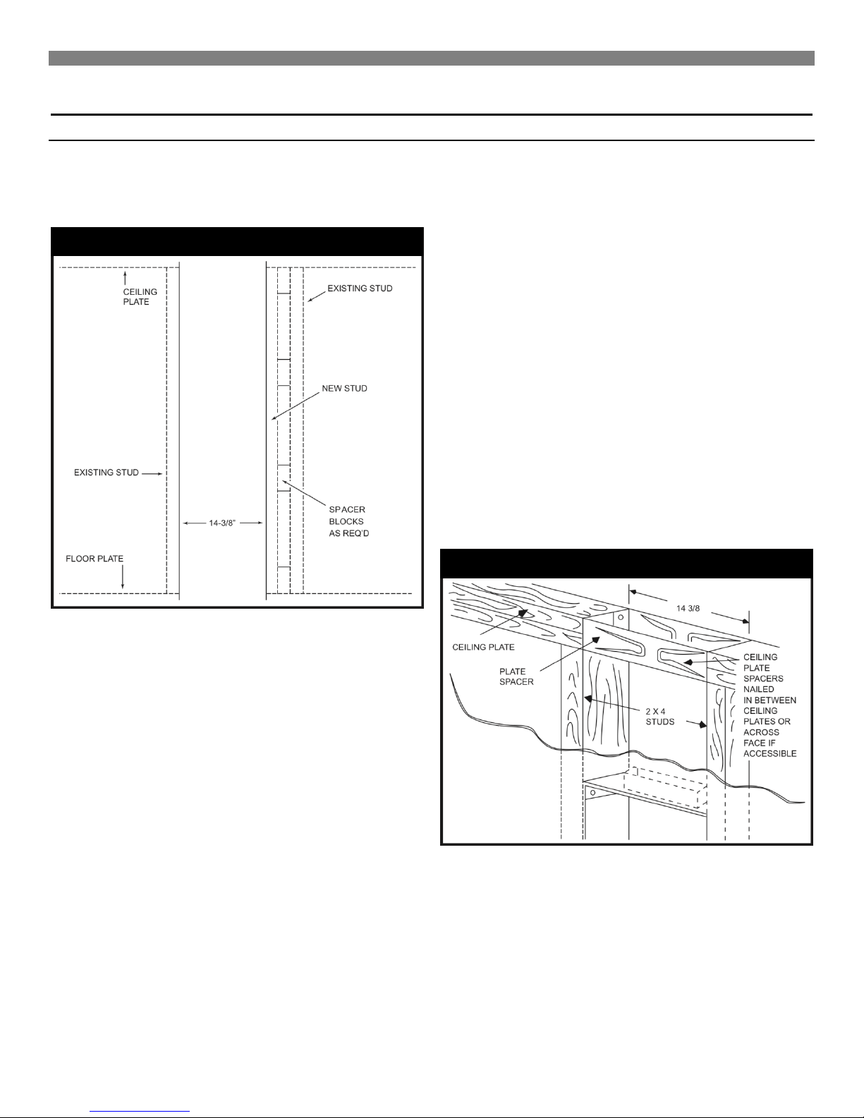
FIGURE 6 – Close Off Stud Space
FIGURE 7 – Ceiling Plate Opening
Installing Your Furnace
Recessed Wall Mount Installation (continued)
CLOSE OFF STUD SPACE (If Required)
If studs are not on 16-inch centers, cut the hole for the furnace
next to an existing stud and frame in the other side using a 2x4
and spacer blocks as required. (Figure 6).
I
INSTALL VENT BASE PLATE (HOLD-DOWN PLATE)
Position base plate on top of header plate and fasten with screws.
Note: Hold down plate is not included.
HEADER PLATE (VENT SUPPORT)
Measure upward 62¼-inches from the top of the floor plate. Place
a mark on each stud at this distance. (Figure 5). Place the
header plate between the studs with the lower edges even with
marks on the studs. Make sure header plate is level.
Locate rear edge of nailing tabs at back of the header. Nail
header plate to the 2x4 studs which will center the vent collar in
the wall. (Figure 5).
INSTALL CEILING PLATE SPACER
Nail the ceiling plate spacers either across or in between the cut
out section of ceiling plate. If nailed between, ends must be bent
at 90 degrees. They must be fastened along each long edge of
the ceiling plate hole to hold the oval vent pipe in the center of the
hole. Ceiling plate spacers preserve structural strength and
position oval vent pipe in the center of the cut out opening.
Ceiling plate spacers are not included. (Figure 7).
CEILING PLATE OPENING
Cut away the ceiling plate between the studs where the furnace is
to be installed. Work from the top in the attic. If there is no
access to the top, remove the wall covering between the two wall
studs all the way to the ceiling. Work through this opening. Cut
out the entire plate so the plate edges will be even with the inner
face of the 2x4 studs. (Figure 7).
Page 12
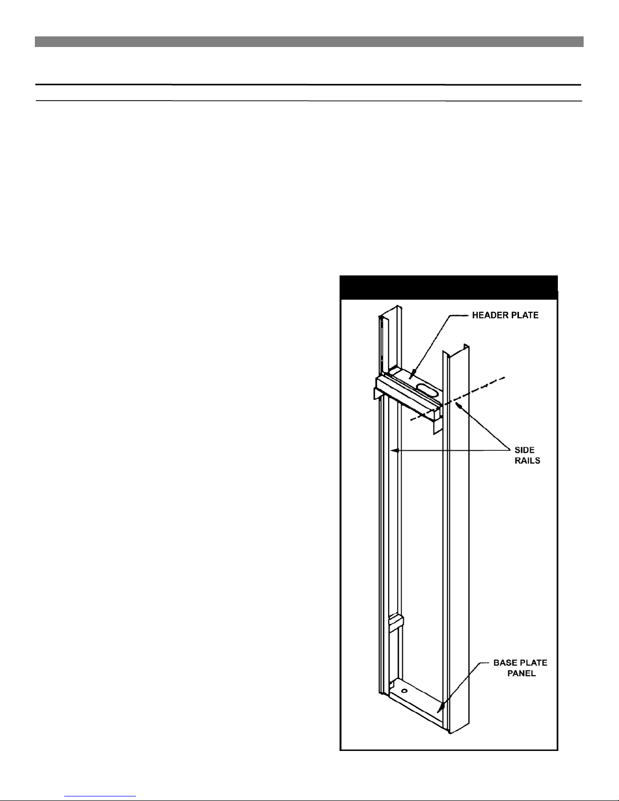
12
FIGURE A
Installing Your Furnace
Surface Mount Installation
The use of the optional Free Standing Accessory No. 4901 allows
single-sided furnaces to be surface mounted instead of recessed
into a wall. This is ideal for remodeling existing masonry wall
construction or when studding is substandard. This kit drastically
cuts installation time and eliminates the expense of cutting into
the walls and ceiling plates. Be sure this accessory is of the type
and design required for the use with your furnace.
NOTE: After picking a location that meets the requirements,
check the wall, attic, and roof to make sure there are no
obstructions such as pipes, electrical wiring, etc., which could
interfere with the installation of the furnace or vent pipe. If
required, move them or pick a new location.
FIND THE WALL STUDS OR CEILING JOISTS
Find two studs or joists at the spot where the furnace is to be
located. Use a stud locator or small finishing nails. Repeatedly
drive and remove a nail into the wall or ceiling in the area of the
stud or joust until you find it. Then find the its side and leave the
nail there. Drive another nail just on the other side other the same
stud or joist.
The inside of the next stud or joist should be about 14½ inches
from the first one found. Drive a nail on the inside of this stud or
joist.
Using the nails as a guide, draw two lines down the side of the
wall from the ceiling to locate the furnace and ceiling hole cutout
for venting.
FREE STANDING ACCESSORY ASSEMBLY & INSTALLATION
Utilizing the holes provided in the furnace legs, secure the
furnace to the brackets attached to the bottom panel with two
(2) #10, ¾” screws.
9. Install the vent enclosure panel, fastening it to the side rails
with six (6) #6, ⅜” screws. Trim the bottom of the panel to fit
the header plate.
10. Install gas inlet through the back wall or one of the two holes
provided in the bottom base plate panel. (Figure D.) Connect
gas line to furnace. See Gas supply and Piping, page 17.
11. Install furnace face panel. See Front Panel Installation,
page 18. NOTE: The panel recesses ¼-inch between the
vertical edges of the enclosure.
1. Attach the base plate panel as shown in Figure A to the
bottom of the side rails with four (4) # 6, ⅜” screws.
2. Attach the header plate, (included with the furnace), to the
side rails using four (4) #8, ⅜” screws. Flanges of the header
plate go against the wall. (Figure A).
3. Install extension side rails as shown in Figure A, by
telescoping them inside the lower side rails. Adjust the
extension side rails by sliding them up or down to ceiling
height. Maximum: 8 feet 9 inches, Minimum: 7 feet 9 inches.
4. If the wall has a baseboard, cut the baseboard out to fit
against the side rails. Stand the side rails against the wall and
fasten them to the wall securely with screws or bolts in the
holes provided. Use a level to assure the enclosure is plumb.
Screws and bolts for wall fastening are not included.
5. After positioning the enclosure, cut a 3½ X 14 inch hole in the
ceiling, centered between the studs or joists as shown in
Figure B.
6. Cut ¼ inch off each end of the ceiling spacer plate. Place the
ceiling spacer plate to the back of the wall and centered in the
enclosure as shown in Figure C.
7. Install Type B/W vent though the roof and studs or joists in
accordance with the installation instructions packed with the
furnace and local codes. See Vent Installation, page 14.
8. Set the furnace body into position. (Figure 9), page 15. The
furnace legs will rest on the bottom of the base plate panel.
Page 13
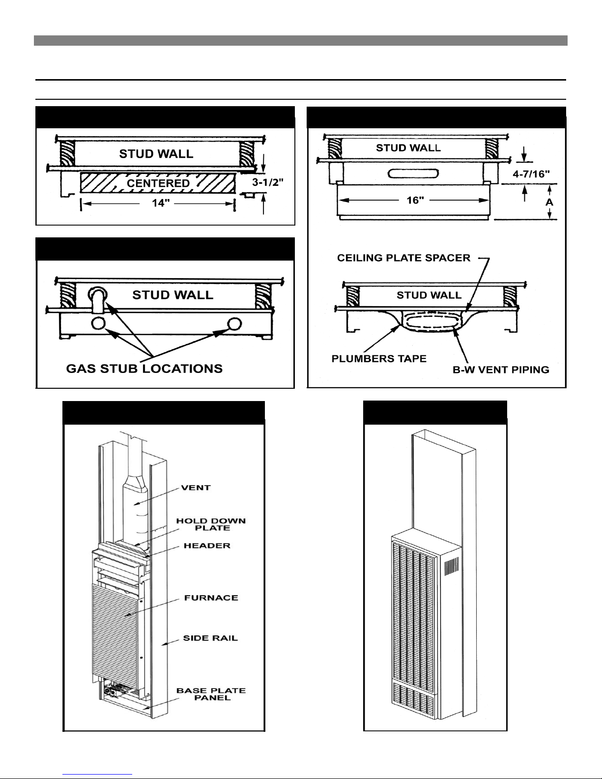
FIGURE B
FIGURE C
FIGURE D
Vent Installed
Front panel installed
Installing Your Furnace
Surface Mount Installation (continued)
Page 14
14
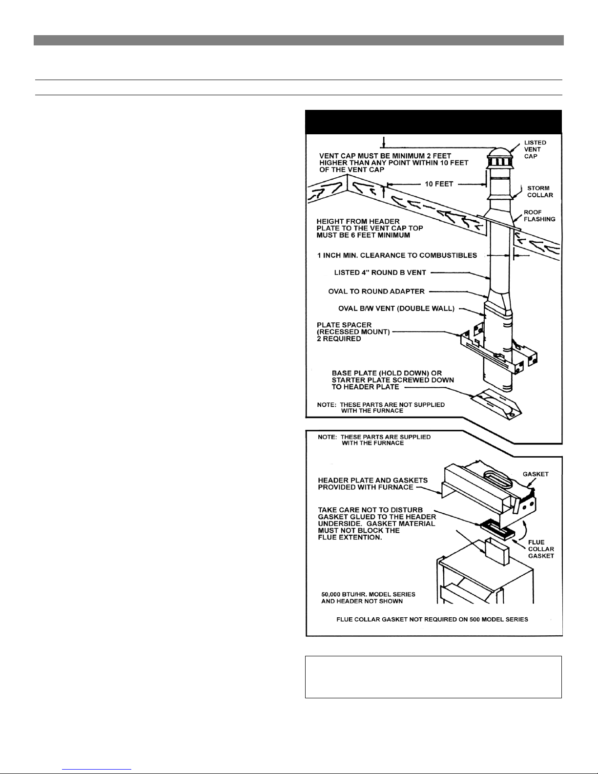
Figure 8 – Typical Vent Installation
CAUTION: To avoid damage to wiring, be sure to
route the wires away from the path of the furnace
Installing Your Furnace
Vent Installation
The vent installation must comply with all local codes and
ordinances. If in doubt, consult your local codes or inspector.
The furnace vent must be directed to the outdoors so that harmful
combustion gases will not collect inside the building.
This furnace must not be connected to a chimney flue serving a
separate solid-fuel burning appliance.
This product is design certified to ANSI Z21.86. It must be
installed with a U.L. tested and listed type "B" approved vent and
type "B/W” approved vent (Figure 8). Older style terra-cotta,
transite, clay, concrete or masonry type vent pipe cannot be used
with this appliance. These types of vent pipe will not heat fast
enough to establish a draft, which will result in improper venting of
combustion products. Consequently, this could cause the vent
safety control system to shut down the furnace.
The area above header within the stud space MUST be kept clear
of any attic insulation to allow the free circulation of air around the
oval vent piping. In some areas the building code requires the
use of an attic shield.
The B/W vent must extend through the ceiling and roof
terminating at least 12-feet above the finished floor on which the
furnace rests.
INSTALL FURNACE VENT
Attach a 4-foot length of oval, double-wall vent pipe through the
plate spacers to the hold-down plate. Push the vent pipe into the
hold-down plate until it is completely seated. The hold-down cleat
will engage the groove in the vent pipe.
COMPLETE THE VENTING
Type B/W gas vent shall extend from the header plate of the
furnace to a point above the highest ceiling plate within the stud
space through which the vent passes, without any offsets or
crossovers. The first vent pipe offset, (if required), may not be any
closer than 2-feet from the header. After a type B/W gas vent
passes through the highest ceiling plate within a stud space
above the furnace to which it serves, the vent system may be
completed with a Type B gas vent, from the SAME manufacturer
(do not mix brands of pipe). Offsets cannot be greater than 45
degrees from vertical. Refer to The Uniform Mechanical Code.
Install the oval-to-round adapter. Complete the piping extending it
through the roof. Use a 4-inch round, double-wall (Type B) vent
pipe, roof flashing, storm collar and vent cap as shown. The vent
cap must be at least 2-feet higher than any point that is within 10feet of the vent cap. There must be at least a 1-inch clearance
between the vent pipe and any combustible material.
Page 15
25,000 & 35,000
Attaching Your Furnace
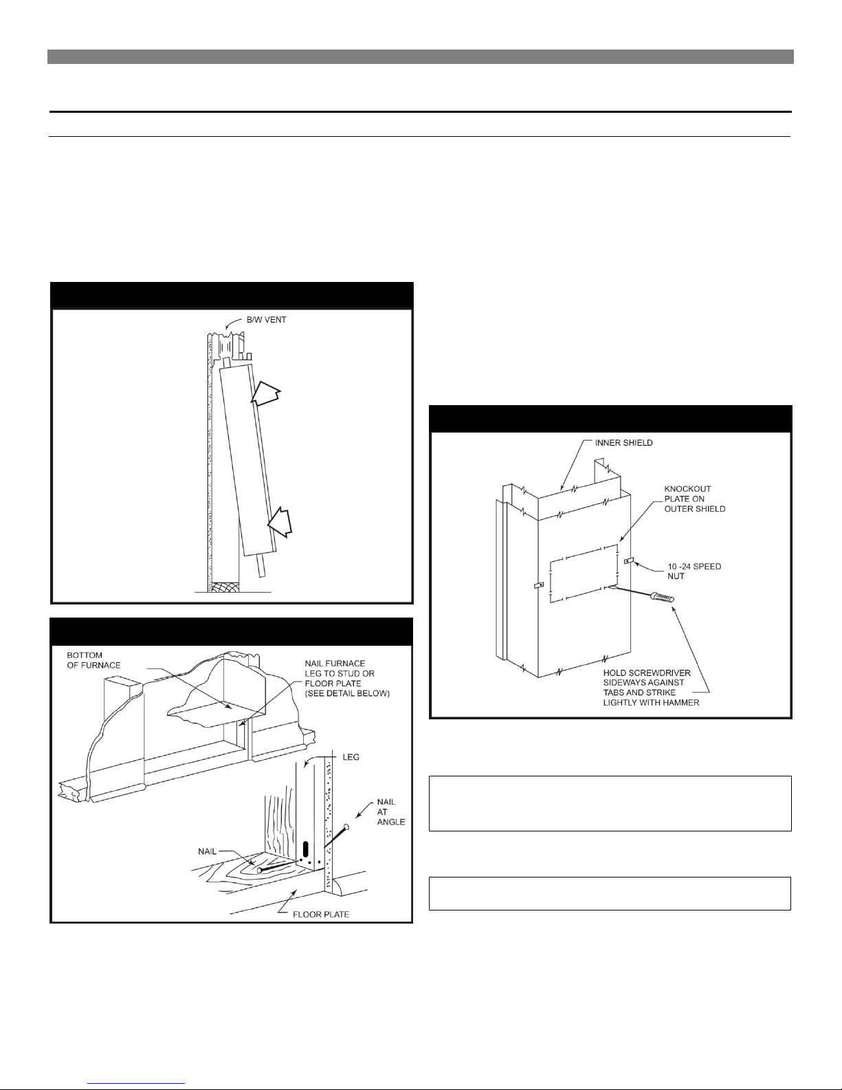
FIGURE 9 – Insert Furnace
FIGURE 11- Remove Knockout Plates11 -
CAUTION: Do not install rear outlet kit where
grille may be blocked by a door, curtains, or any
other obstruction.
FIGURE 10 – Nail Placement
WARNING: Never shear or cut the furnace legs.
Installing Your Furnace
Attaching Your Furnace
Clear the wall recess of all debris, remove any wood or plaster.
Stand the furnace in front of recess, holding the furnace body at
an angle. Insert flue collar into the opening in the header plate
and raise furnace carefully (Figure 9). Swing bottom of furnace
into wall recess with front edges of legs flush with 2x4 floor plate.
In the holes provided, nail through the legs into studs or floor plate
(Figure 10).
REAR OUTLET KIT INSTALLATION (OPTIONAL)
If a Rear Outlet Register Accessory is used, the following
procedure must be completed before placing furnace body into
wall recess. (Figure 11). Attach speed nuts to outer shield and
remove knockout plates from both the outer and inner shields as
follows:
1. Punch in the lower corners with a screwdriver blade.
2. Break the knockout side and bottom connecting tabs by
holding a screwdriver blade sideways against the tab and
striking the head of the screwdriver lightly with a hammer.
3. Swing the plate outward; bend it back and forth to break the
top tabs. Use caution when handling sharp metal edges.
Btu/hr. Models
Do not damage gasket glued to underside of header plate when
placing furnace in wall. Avoid nailing the legs so tightly that it
disturbs the inner furnace casing. Do not try to force the furnace
into a smaller-than-specified recess.
Page 16
16
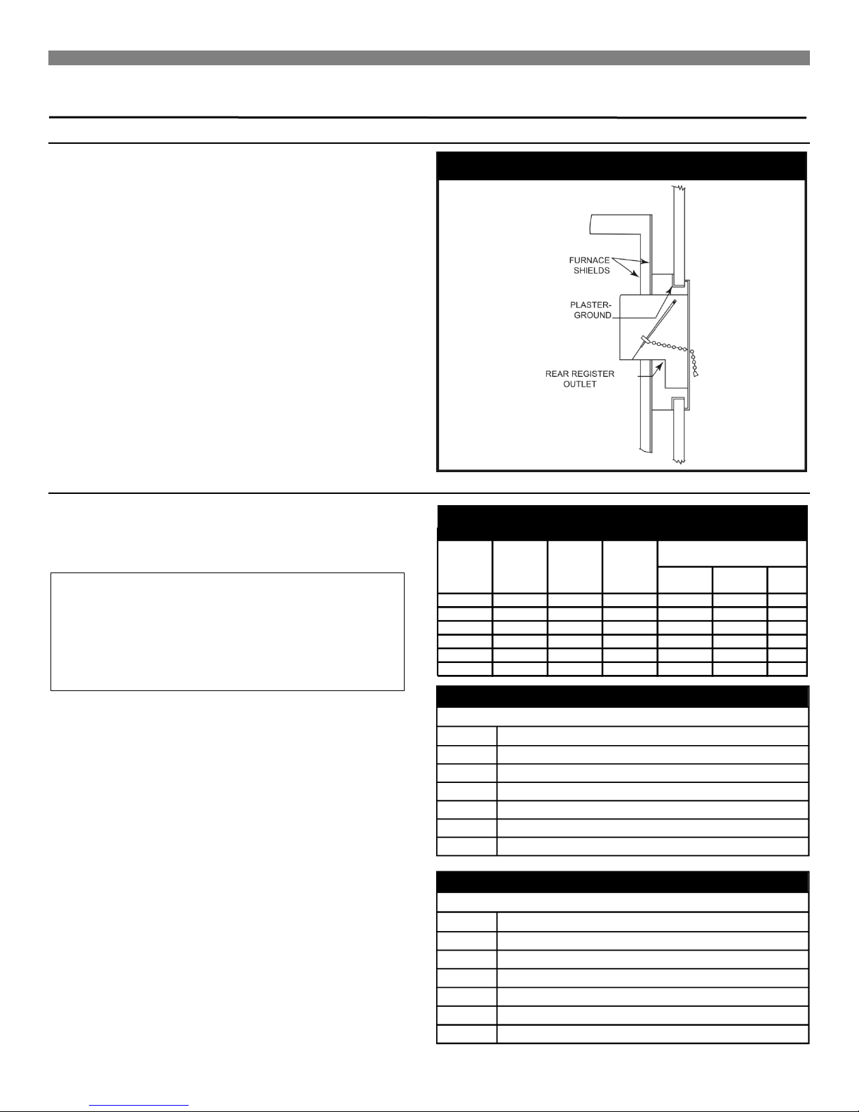
2509622 Nat. 25,000 19,350 #43 0.089 1
2509621 L.P. 25,000 19,350 #54 0.055 1
3509622 Nat. 35,000 25,930 #38 0.101 1
3509621 L.P. 35,000 25,930 #52 0.063 1
5009622 Nat. 50,000 38,000 #44 0.086 2
5009621 L.P. 50,000 38,000 #54 0.055 2
Furnace Technical Information
Main Burner Orifice
Drill
Dec.
Qty.
Heating
Capacity
Rating
Btu/hr.
Input
Rating
Btu/hr.
Gas Type
Model
Number
FIGURE 12 – Mounting Rear Outlet Register
The gas control valve, in the furnace, is shipped with a seal over
the gas inlet tapping. Do not remove the seal until ready to
For L.P. gas, the minimum inlet gas supply pressure for the
purpose of input adjustment is 11-inches water column. The
For natural gas, the minimum inlet gas supply pressure for the
purpose of input adjustment is 5-inches water column. The
Gas pressure and input to the burners must not exceed the rated
input and pressure shown on the nameplate. The natural gas
manifold pressure should be 4-inches water column. The
manifold pressure should be 10-inches water column for L.P. gas.
operation in elevations above 2,000 feet, a burner orifice
change may be required to suit the gas supplied. Check with
The efficiency rating of this appliance is a product thermal
efficiency rating determined under continuous operating
conditions and was determined independently of any installed
system. For elevations above 4,500 feet, reduce ratings 4% for
WARNING: Danger of property damage, bodily injury or
death. Make sure the furnace is equipped to operate on
the type of gas available. Models designed as natural gas
are to be used with natural gas only. Models designed for
use with liquefied petroleum (L.P) gas have orifices sized
for commercially pure propane gas. They cannot be used
with butane or a mixture of butane and propane.
Gas Conversion Kits
Natural Gas to L.P. Gas
Model
Description
8901
25096 Series with Williams Brand Gas Valve
8902
35096 Series with Williams Brand Gas Valve
8903
50096 Series with Williams Brand Gas Valve
7675
25096 Series with Robertshaw Brand Gas Valve
7676
35096 Series with Robertshaw Brand Gas Valve
7677
50096 Series with Robertshaw Brand Gas Valve
Gas Conversion kits
L.P. Gas to Natural Gas
Model
Description
8904
25096 Series with Williams Brand Gas Valve
8905
35096 Series with Williams Brand Gas Valve
8906
50096 Series with Williams Brand Gas Valve
9911
25096 Series with Robertshaw Brand Gas Valve
9912
35096 Series with Robertshaw Brand Gas Valve
9913
50096 Series with Robertshaw Brand Gas Valve
Furnace Technical Information
Installing Your Furnace
Attaching Your Furnace (continued)
After furnace is in position, install rear outlet register as shown in
Figure 12. Have damper in open position when inserting the
assembly. Secure the rear outlet register to speed nuts with the
machine screws furnished.
Gas Supply and Piping
GAS PIPING
The gas supply line must be of adequate size to handle the Btu/hr.
connect the piping.
requirements and length of the run for the unit being installed.
Determine the minimum pipe size from Figure 17, basing the
length of the run from the gas meter or source to the unit.
All piping must comply with local codes and ordinances or with the
National Fuel Gas Code (ANSI Z223.1 NFPA No. 54), whichever
applies. (In Canada: CAN/C.G.A B149). Refer to Figure 18 for
the general layout of the unit. It shows the basic fittings needed.
The following rules apply:
GAS SUPPLY
1. Use new, properly reamed pipe free from chips such as
steel or black iron pipe and fittings or other approved by
local codes.
maximum inlet gas supply pressure is 13-inches water column.
2. Do not thread pipe too far. Valve distortion or malfunction
may result from excess pipe within the control. Apply a
moderate amount of good quality dope to pipe only. Leave
the two end threads bare. If L.P. gas installation, use
maximum inlet gas supply pressure is 7-inches water column.
compound resistant to action of liquefied petroleum gases.
3. Use ground joint unions.
4. Install a drip leg (sediment trap) to trap dirt and moisture
before it can enter the gas valve. The nipple must be a
For
minimum of 3-inches long.
5. Install a manual shut-off valve.
your local gas supplier.
6. Provide a 1/8 NPT test gauge connection immediately
ORIFICE SIZES
before the gas supply connection to the furnace.
Gas Supply and Piping (continued)
each 1,000 feet above sea level.
Page 17
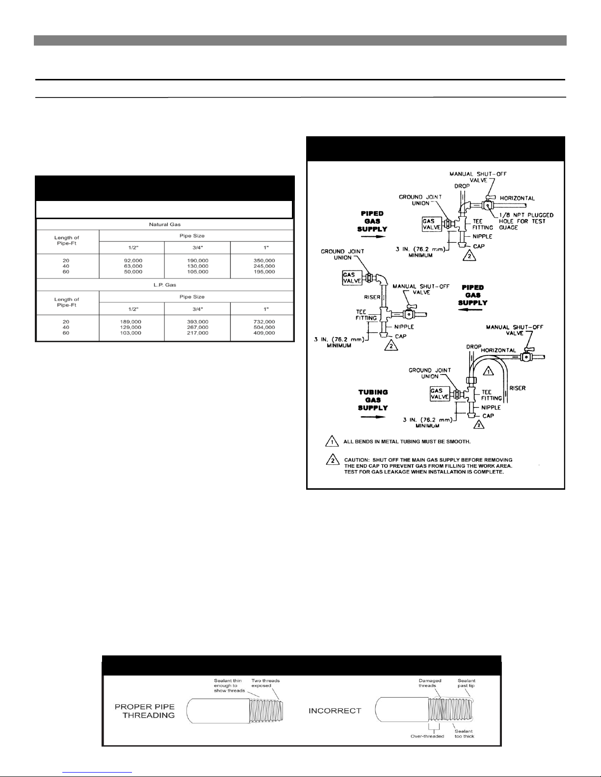
FIGURE 14 – Gas Piping
FIGURE 15 – Proper Piping Practice
Pipe Capacity – Btu/hr. with Fittings
FIGURE 13 – Pipe Capacity
Installing Your Furnace
Gas Supply and Piping (continued)
GAS PIPING
The gas supply line must be of adequate size to handle the Btu/hr.
requirements and length of the run for the unit being installed.
Determine the minimum pipe size from Figure 13, based on the
length of the run from the gas meter to the unit.
All piping must comply with local codes and ordinances or with the
National Fuel Gas Code (ANSI Z223.1 NFPA No. 54), whichever
applies. (In Canada: CAN/C.GA B149). Refer to FIGURE 14 for
the general layout of the unit. It shows the basic fittings needed.
The following rules apply:
1. Use new, properly reamed steel or black iron pipe and
fittings free of metal chips and debris that are approved by
local codes. Metal chips and debris can damage the valve.
2. Do not thread pipe too far. Valve distortion or malfunction
may result from excess pipe within the gas control valve.
Apply a moderate amount of good quality dope to the pipe
only. Leave the two end threads bare. (Figure 15). L.P.
gas installations require a dope compound resistant to the
action of liquefied petroleum gases. Excess dope going into
the valve may cause it malfunction.
3. Use ground joint unions.
4. Install a drip leg (sediment trap) to trap dirt and moisture
before it can enter the gas valve. The nipple must be a
minimum of 3-inches long.
5. Install a manual shutoff valve.
6. Provide a 1/8” NPT test gauge connection immediately
before the gas supply connection to the furnace.
GAS CONNECTION
If the installation is for L.P. gas, have the L.P. installer use a two
stage regulator and make all the connections from the storage
tank.
Use two pipe wrenches when making the connection to the valve
to prevent turning and/or damage to the valve.
Connections between the manual shutoff valve and burner control
assembly can be made with an A.G.A./C.G.A. design certified
flexible connector if allowed by local codes. Drip leg and ground
joint unions are still required.
Tighten all joints securely.
Page 18
18
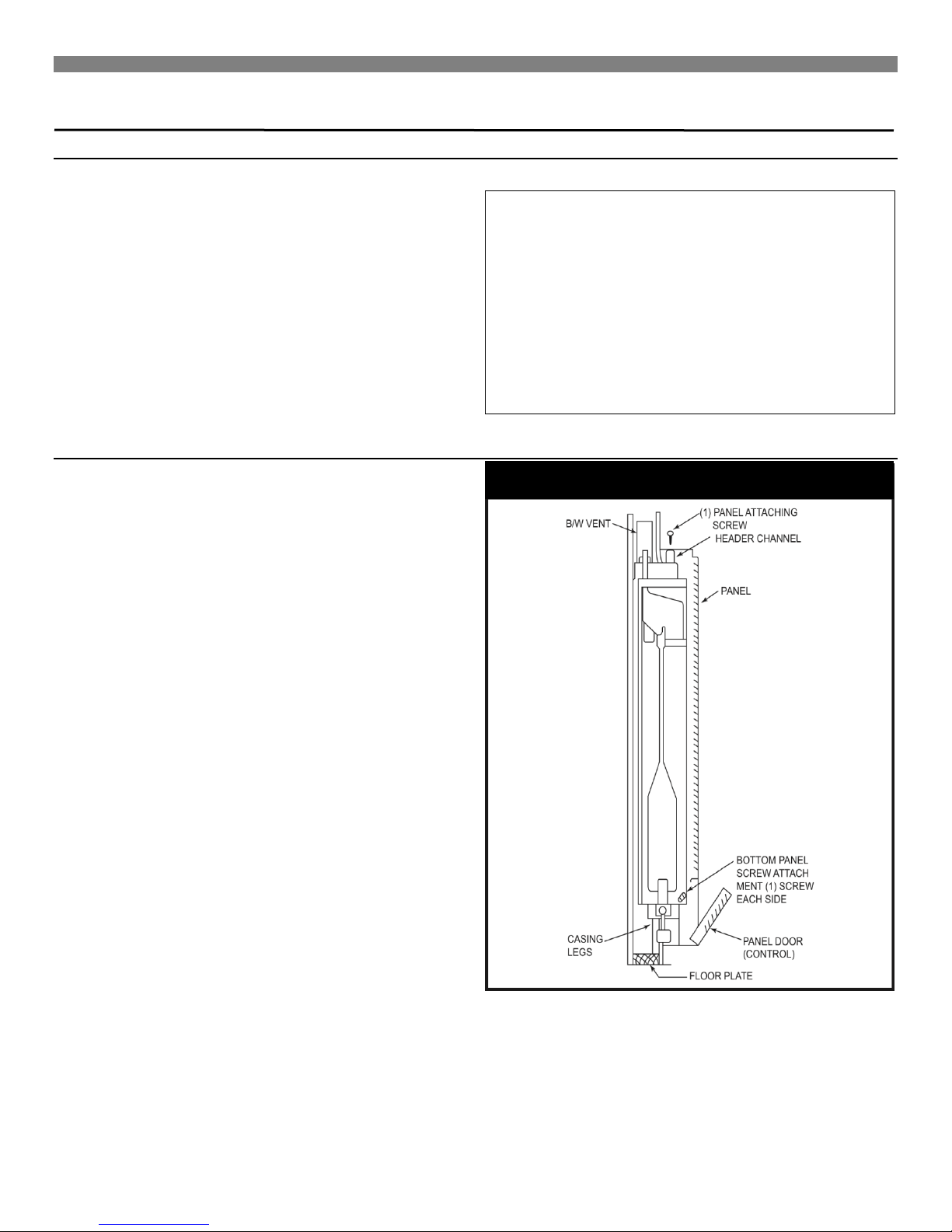
FIGURE 16 – Panel Placement
Installing Your Furnace
Gas Supply and Piping (continued)
CHECKING THE GAS PIPING
Test all piping for leaks. When checking gas piping to the furnace
with gas pressure less than 1/2 PSI, shut off manual gas valve to
the furnace. If gas piping is to be checked with the pressure at or
above 1/2 PSI, the furnace and manual shutoff valve must be
disconnected during testing. (SEE WARNING). Apply soap
solution (or a liquid detergent) to each joint. Bubbles forming
indicate a leak. Correct even the slightest leak at once.
Front Panel Installation
Place the front panel top over the channel on the header plate,
as shown in Figure 16. Press the panel tight against wall, and
secure it to the header channel with the screw provided in final
assembly package. Open the control door at bottom of panel
and fasten the panel at each side through slots in flanges with
screws provided.
Attach handle to the front panel door with the screw provided.
Install the second face panel in same manner for 500 Series
models.
WARNING: Danger of property damage, bodily
injury or death. Never use a match or open flame
to test for leaks. Never exceed specified pressures
for testing. Higher pressures may damage the gas
valve and cause over-firing which may result in
component(s) failure. L.P. gas is heavier than air
and may settle in any low area, including open
depressions and it will remain there unless the area
is ventilated.
Never attempt start-up of unit before thoroughly
ventilating the area and smelling near the floor for
gas odor.
Page 19
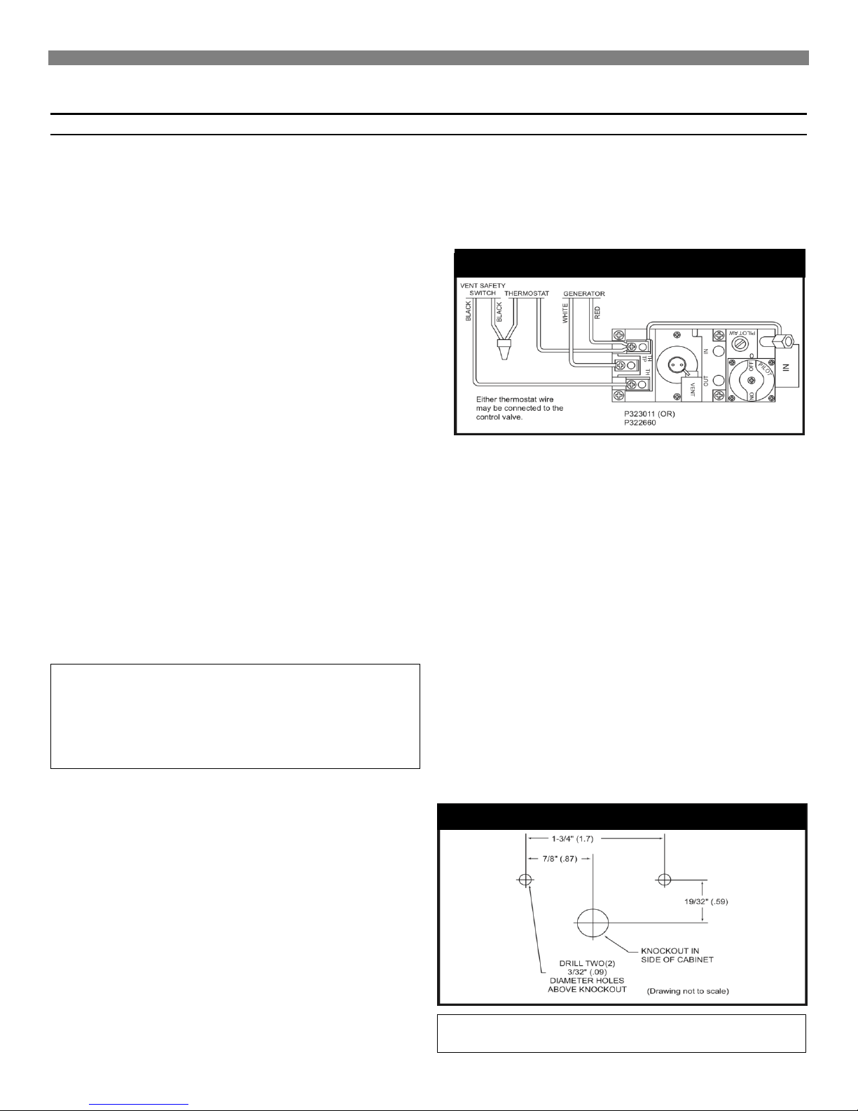
FIGURE 17 – Thermostat Wiring
FIGURE 18 Knockout Holes
IMPORTANT: Keep the thermostat wires away from the
combustion chamber.
Installing Your Furnace
Thermostat Installation
Williams’ furnaces are operated by a millivolt type thermostat.
Current to the thermostat is supplied by the pilot generator. Do
not connect it to electricity. Anticipator settings are not required.
1. Use of existing wire is acceptable if it is in a satisfactory
location and the wire is in good condition. When in doubt,
use new wiring.
2. If a new location is chosen or if this is a new installation,
thermostat wire must first be run to the location selected.
All wiring must agree with local codes and ordinances.
These instructions cover bringing the wire down from the
attic but it may be run from a basement or crawl space
using similar methods.
3. Before drilling a hole in the wall at the selected location,
drive a small finish nail through the ceiling in the corner of
the wall and ceiling above the thermostat location. Pull the
nail out and push a small, stiff wire through the hole so it
can be found in the attic. Drill a ½-inch hole through the
ceiling wall plate.
4. Probe for obstructions in the partition. Then, drill a ½-inch
hole through the wall at the selected location for the
thermostat.
5. From the attic, feed the thermostat wire through the wall
until even with the thermostat location.
6. Snag the thermostat wire through the hole and pull the wire
through the hole in the wall so that 6-inches of the wire
protrude.
7. Route wires to the furnace.
8. Never use nails or staples across the thermostat wires.
CAUTION: Label all wires prior to disconnection
when servicing controls. Wiring errors can cause
improper and dangerous operation. Verify proper
operation after servicing. Refer to installation
instructions packed in the thermostat carton if you
have any doubt about the above procedures.
WALL-MOUNTED THERMOSTAT INSTALLATION
1. To remove the thermostat cover, squeeze both sides and lift.
2. Connect the thermostat wires to the terminal screws on the
base of thermostat.
7. Use the 18-gauge wire as supplied for a maximum length of
20-feet. If a longer length is needed, use 16-gauge wire to
a maximum length of 25-feet.
8. Connect the thermostat wires to the control valve as shown
in Figure 17.
FACE PANEL-MOUNTED THERMOSTAT INSTALLATION
1. Before removing the face panel, disconnect the thermostat
wires at the gas valve.
2. Locate the knockout on the right side of the furnace to
mount the thermostat. Remove the knockout by tapping it
lightly with a screwdriver (Figure 18). It will also be
necessary to cut a 1/2-inch hole in the inside panel
insulation for clearance to the knockout.
3. Cut the thermostat wire to 56 inches.
4. Connect the thermostat wires to terminal screws on the
thermostat base.
5. Feed the thermostat wires through the knockout and route
them through the metal clip to the gas valve.
6. Mount the thermostat to the side of the cabinet with screws
provided.
7. Replace the thermostat cover.
8. Connect the thermostat wires to the control valve as shown
in Figure 17.
3. Push any excess wire back through hole in the wall and
plug hole with insulation to prevent drafts from affecting
thermostat operation.
4. Be sure to level the thermostat for best appearance. Fasten
thermostat base to the wall through mounting holes with
screws provided.
5. Replace the thermostat cover.
6. Do not run wire in any location where it might be damaged.
Avoid splicing the thermostat wires unless the spliced wires
are properly cleaned, soldered and taped.
Page 20
20
Type of Gas
Manifold Pressure, In. W.C.
Natural
4.0
L.P.
10.0
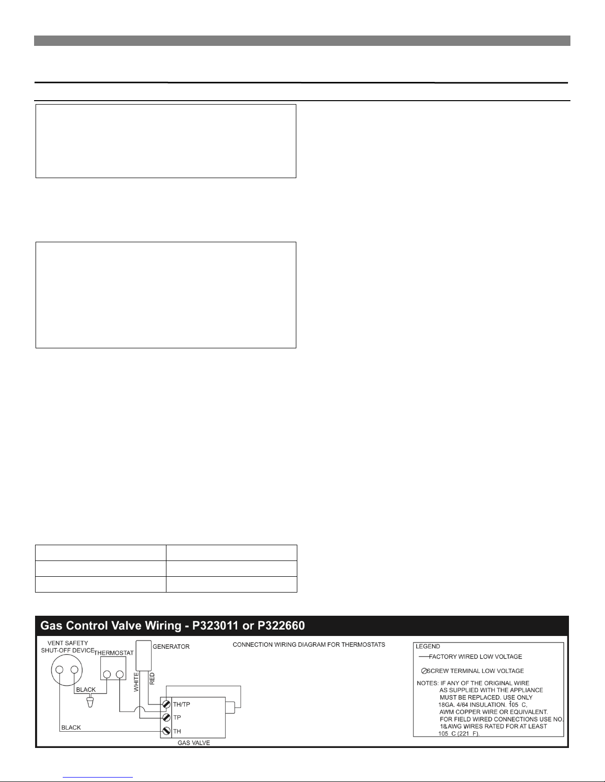
CHECK GAS CONTROL VALVE WIRE CONNECTIONS
Installing Your Furnace
Start-Up Procedure
WARNING: Danger of property damage, bodily
injury or loss of life. Liquefied Petroleum (L.P.) Gas
is heavier than air and may settle in any low area,
including open depressions and may remain there
unless area is ventilated. Never attempt start-up of
unit before thoroughly ventilating the area.
Check the furnace operation as outlined in the following
instructions. If any sparking, odors or unusual noises are
encountered, shut off electric power immediately. Recheck for
wiring errors or obstructions in or near fan motor (if equipped).
WARNING: Natural gas heating value (Btu per
cubic foot) can vary significantly. Therefore, it is
the installer's responsibility to see that Btu/hr. input
to the furnace is adjusted properly. Failure to do so
could cause combustion chamber failure,
asphyxiation, fire or explosion resulting in damage,
bodily injury or death. Refer to the National Fuel
Gas Code (NFPA 54) to be sure the furnace is
burning fuel at the proper rate.
CHECK GAS INPUT AND PRESSURES
For furnaces located at elevations between sea level and 4,500
feet, the measured input must not be greater than the input shown
on the nameplate of the furnace. For elevations above 4,500 feet,
the measured input must not exceed the input on the nameplate
reduced by 4 percent for each 1,000 feet that the furnace is above
sea level.
Gas supply pressure and manifold pressure with the burner(s)
operating must also be as specified on the nameplate.
Rated input will be obtained on a heating value of 2,500 Btu/hr. for
propane at 10-inches manifold pressure with factory-sized
orifices. If L.P. gas having a different heating value is supplied,
orifices must be changed by a qualified service technician before
the furnace is operated.
CHECK THE MANIFOLD GAS PRESSURE
A tapped opening is provided in the gas valve to facilitate
measuring manifold gas pressure. A water column manometer
having a scale range from 0 to 12-inches of water column should
be used for this measurement. The manifold pressure must be
measured with the burner and pilot operating. Any major changes
in the flow must be made by changing the size of the burner
orifice.
CHECK THE GAS INPUT (NATURAL GAS ONLY)
Under firing could cause inadequate heat, excessive
condensation or ignition problems. Over firing could cause
shooting flame impingement or overheating of the combustion
chamber. Before starting natural gas input check, obtain the
heating value of gas (Btu per cubic foot) at standard conditions
from your local gas supplier.
To measure the input, using the gas meter, proceed as follows:
1. Turn off gas supply to all other appliances except the
furnace.
2. With the furnace operating, time the smallest dial on the
meter for one complete revolution. If this is a 2-cubic-foot
dial, divide the seconds by 2. If it is a 1-cubic-foot dial, use
the time in seconds as is. This gives the seconds per cubic
foot of gas being delivered to the furnace.
3. Assuming natural gas with a heating value of 1,000 Btu per
cubic foot and 34-seconds per cubic foot used as
determined by step (2), then:
Seconds per hour = 3,600
Input = 1,000 x 3,600 / 34 = 106,000 Btu/hr.
This measured input must not be greater than the input
indicated on the nameplate of the furnace.
4. Relight all other appliances turned off in Step 1 above. Be
sure all pilots are operating.
CHECK THERMOSTAT
Check thermostat operation. When set above room temperature
shown on the thermostat, the main burner should light. Make
certain the thermostat turns off the furnace when the room
temperature reaches the selected setting and starts the furnace
when room temperature falls a few degrees below the thermostat
setting.
Page 21
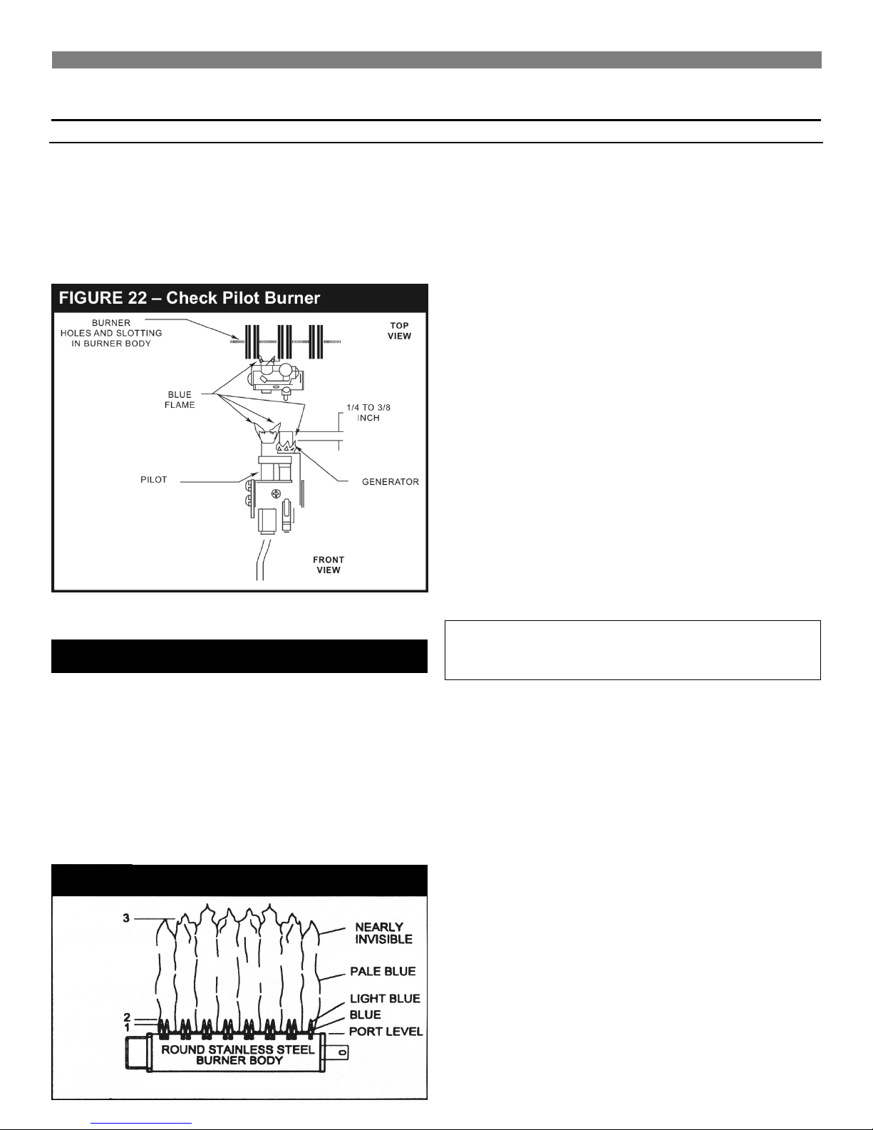
FIGURE 19 – Check Pilot Burner
FIGURE 20 – Burner Flame Characteristics
Operating Your Furnace
Start-Up Procedure (continued)
CHECK PILOT BURNER
The pilot flame must surround the generator tip from 1/4 to 3/8-
inches. Pilot flame is preset at the factory, so ordinarily it does not
require field adjustment. (Figure 19). On new installations, the
gas lines will be filled with air and may take several minutes to
establish a pilot flame.
BURNER FLAME CHARACTERISTICS
Start the furnace and let it operate at least ten minutes. Open the
access door to view the burner flame. Limit your movements near
the furnace a few more minutes before making your final
observations. The flame may look yellow due to dust particles in
the room air. The flame should change to a nice blue color with
firm inner and secondary cones. An occasional flash of orange
might be seen as dust particles burn in the flame. This is normal.
No burner adjustment is provided, or is necessary. (Figure 20).
NORMAL APPEARANCE
Natural Gas:
1. Inner coneblue in color3/8 to 5/8-inches above ports.
2. Secondary inner conelight blue in color1 to 2-inches
above ports.
3. Total flamefrom blue in color to nearly invisible
approximately 6-inches above ports.
L.P Gas:
1. Inner coneblue in color1/2 to 3/4-inches above ports.
2. Secondary inner conelight blue in color1 to 2-inches
above ports.
3. Total flamefrom blue in color to nearly invisible
approximately 6-inches above ports.
ABNORMAL APPEARANCE
Lazy Flame:
Long, soft yellow cones moving around in the combustion
chamber lifting from ports (insufficient air).
Extremely Fast Flame:
Flame will not hold to portsentire cone sections blow off from
noisy ports (too much pressure).
WARNING: If flame appears abnormal, contact the
gas company or a qualified service technician
immediately.
Page 22
22
IMPORTANT:
KEEP BURNER AND CONTROL COMPARTMENT CLEAN.
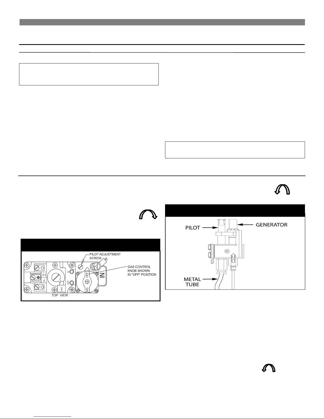
FIGURE 21 – Gas Control Knob
FIGURE 22 – Pilot and Generator
Operating Your Furnace
FOR YOUR SAFETY, READ BEFORE LIGHTING THE PILOT
WARNING: If you do not follow these instructions
exactly, a fire or explosion may result causing
property damage, personal injury or loss of life.
LIGHTING THE PILOT
A. This appliance has a pilot which may be lit by hand. When
lighting the pilot, follow these instructions exactly.
B. BEFORE LIGHTING smell around the appliance area for gas.
Be sure to smell next to the floor because some gases are
heavier than air and will settle on the floor.
C. Use only your hand to push in or turn the gas control knob.
Never use tools. If the knob will not push in or turn by hand,
don't try to repair it, call a qualified service technician. Force
or attempts to repair may result in a fire or explosion.
OPERATING INSTRUCTIONS
1. STOP! Read the safety information above.
2. Set the thermostat to lowest setting.
3. If applicable, turn off all electric power to the appliance.
4. Open control access panel.
5. Push in gas control knob slightly and turn clockwise
to "OFF". (Figure 21).
6. Wait five (5) minutes to clear out any gas, then smell for gas,
including near the floor. If you then smell gas, STOP! Follow
"E" in the safety information above. If you don't smell gas, go
to the next step.
7. Loosen wing nut and open the pilot observation door (if
equipped).
8. To find the pilot, follow metal tube from the gas control. The
pilot is mounted on the side of the burner. (Figure 22).
D. Do not use this appliance if any part has been under water.
Immediately call a qualified service technician to inspect the
appliance and to replace any part of the control system and
any gas control which has been under water.
E. WHAT TO DO IF YOU SMELL GAS
• Do not try to light any appliance or strike a match.
• Do not touch any electrical switch; do not use any phone or
cell phone in your building.
• Immediately call your gas supplier from a neighbor's phone.
Follow the gas supplier's instructions.
• If you cannot reach your gas supplier, call the fire
department.
9. Turn knob on the gas control counterclockwise to
"PILOT".
10. Push in the control knob all the way and hold in. Immediately
light the pilot. Continue to hold the control knob in for about
one (1) minute after the pilot is lit. Release the knob and the
pilot flame will pop back up. The pilot should remain lit. If it
goes out, repeat Steps 5 through 10.
• If knob does not pop up when released, stop and
immediately call your service technician or gas supplier.
• If the pilot will not stay lit after several tries, turn the gas
control knob "OFF” and call your service technician or gas
supplier.
11. Close pilot observation door, tighten wing nut (if equipped).
12. Turn gas control knob counterclockwise to "ON”.
13. Close control access panel.
14. Turn on all electric power to the appliance (if applicable).
15. Set thermostat to desired setting.
Page 23
IMPORTANT:
KEEP BURNER AND CONTROL COMPARTMENT CLEAN.
OPERATION OF YOUR FURNACE
WARNING: Protect your eyes against the danger
of ignition flash and eye injury or blindness. Never
attempt to light the pilot with the gas control valve
knob in the “ON” position. Flashback could occur.
Operating Your Furnace
FOR YOUR SAFETY, READ BEFORE LIGHTING THE PILOT (continued)
TO TURN OFF GAS TO APPLIANCE
1. Set the thermostat to lowest setting.
2. Turn off all electric power to the appliance if service is to be
performed (if applicable).
3. Remove control access panel.
4. Push in gas control knob slightly and turn clockwise
to "OFF". Do not Force.
5. Replace control access panel.
THE FURNACE OPERATES IN THE FOLLOWING SEQUENCE:
1. Thermostat turns on the main burner.
2. Heat builds up in the furnace and starts the fan (if
equipped). The heated air comes out the front panel
louvers.
3. When the thermostat setting is reached, it shuts off the main
burner.
4. The fan runs until the heat is removed from the furnace,
then it turns off (if equipped).
Your furnace is equipped with a 100% safety pilot that will shut off
the gas supply in case the pilot is not burning or functioning
properly. Make sure the pilot is adjusted properly and that the
pilot generator connection at the control valve is tight. If the
furnace will not stay lit, call your local gas utility or a qualified
service person.
If furnace is equipped with a manual spark igniter, follow these
steps:
1. Review the pilot lighting instructions.
WARNING: Due to high surface temperatures,
keep children, clothing, furniture or any combustible
material away from the furnace.
WARNING: The surface of the furnace is hot
during operation. Keep children, clothing, furniture,
and flammable material away from it. Keep all
access doors and panels in place except for
inspection and maintenance. On new installations,
the gas lines will be filled with air and it may take
several minutes to establish the pilot flame.
WARNING: Danger of property damage, bodily
injury or death. If the furnace overheats or fails to
shut off, close manual shutoff gas valve to the
furnace before turning off electrical power to the
accessory fan.
2. When instructed to “Light the Pilot,” depress the red button
located on the burner pan for pilot ignition. If necessary,
depress the red button vigorously several times for pilot
ignition.
3. If pilot fails to ignite or a spark is not present while actuating
the red button or by using a match, repeat steps 5 through
10 listed in "Lighting the Pilot.”
Page 24
24
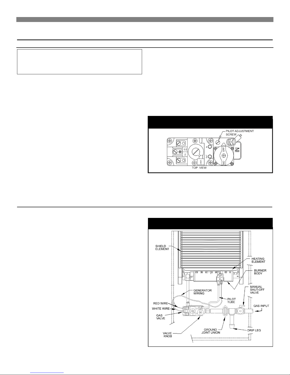
FIGURE 23 – Adjusting the Pilot
FIGURE 24 – Disconnecting Gas Line
Caring for Your Furnace
How to Care for Your Furnace
WARNING: Danger of bodily injury or death. Turn
off electric power supply at disconnect switch, fuse
box or service panel before removing any doors or
access service panels from unit.
ANNUAL UPKEEP NEEDED
It is recommended that a qualified service technician perform
these maintenance checks at the beginning of each heating
season.
CABINET FINISH
Clean cabinet with damp cloth. Never use abrasive cleaners.
Cabinets are finished with heat resistant powder paint. Never
refinish or paint.
FURNACE AREA
Keep the area near the furnace clear and free from combustible
materials, gasoline and other flammable liquids and vapors.
COMBUSTION AND VENTILATION AIR
PILOT BURNER
Using the instructions in "Lighting the Pilot”, leave thermostat at its
lowest setting. Pilot flame should surround the generator tip 1/4
to 3/8-inches. If flame needs adjusting, do so as follows:
1. Insert small screwdriver into the pilot adjusting screw
(Figure 23). Adjust flame as needed. Turn screw
counterclockwise to increase flame, clockwise to decrease.
2. Turn thermostat to highest setting. Main burner should light
quickly and smoothly. Turn thermostat to lowest setting.
Main burner should go out. Pilot should remain lit.
The combustion and ventilation air supply must not be blocked.
Do not put anything in or on the furnace cabinet. For better
circulation and more effective heating, do not place obstructions,
furniture or other items closer than four-feet in front of the furnace
or two-feet from each side of the furnace.
CLEANING BLOWER (IF APPLICABLE)
Shut off electricity. Clean any lint or dirt from fan blades, fan
motor and exposed air passages.
BURNER CLEANING
If cleaning is required, contact a qualified service technician to
clean and service burner. To remove burner(s):
1. Open burner compartment door.
2. Shut off gas supply to furnace.
3. Disconnect gas line inside cabinet at ground joint union
fitting. (Figure 24).
4. Remove (2) screws securing burner pan assembly to inner
liner.
5. Pull burner pan assembly forward approximately 1/2-inch
and drop down to expose the top of the burner.
6. Clean all foreign materials from the top of the burner.
VENT SYSTEM
Make sure that no parts of the venting system are blocked or
rusted. Clean or replace before using the furnace.
7. After cleaning, replace burner pan assembly by reversing
above procedure.
Page 25
Care – 25
Installing Your Blower Accessory
DANGER: The build-up of any dust, lint or foreign
material in the primary air opening of the burner
can interfere with the proper air gas mixture and
can result in a yellow flame which can produce
carbon monoxide and soot. This condition, if
allowed to develop, can lead to bodily injury
including death. It is imperative that the burner be
kept clean.
CAUTION: Danger of property damage, bodily
injury or death. Turn off electric power supply at
the disconnect switch, fuse box or service panel
before removing or working on the fan cabinet.
Caring for Your Furnace
How to Care for Your Furnace (continued)
CLEANING THE BURNER COMPARTMENT
Because cold air is attracted to the flame during furnace
operation, a buildup of lint from carpeting, bedding, dust, etc. in
the burner area will occur. It is necessary to clean this area
regularly. Use a vacuum cleaner with a narrow attachment to
reach small areas. Be careful in and around the pilot. A change
in its adjustment could be made if moved during cleaning. A
properly adjusted burner with nearly all gases will produce a flame
which has clear blue cone having a bluish-red or bluish-violet
outer mantle.
Blower Accessory 2901 and 2907
This blower accessory is installed on the furnace top and
increases circulation of warm air through the heated space. A
115V electrical outlet adjacent to the furnace is required. For
automatic setting, you must select the "HI" or "LOW" fan switch
position. When the furnace heats up, the automatic fan switch will
be activated and the fan will operate. The blower accessory will
not operate if the fan switch is set in the "OFF" (center) position.
Be sure this accessory is of the type and design required for use
with your furnace.
1. Turn off electric power supply at the disconnect switch, fuse
box or service panel before installation or service to the
blower accessory.
2. Label all wires prior to disconnection when servicing. Wiring
errors can cause improper and dangerous operation. Verify
proper operation after servicing.
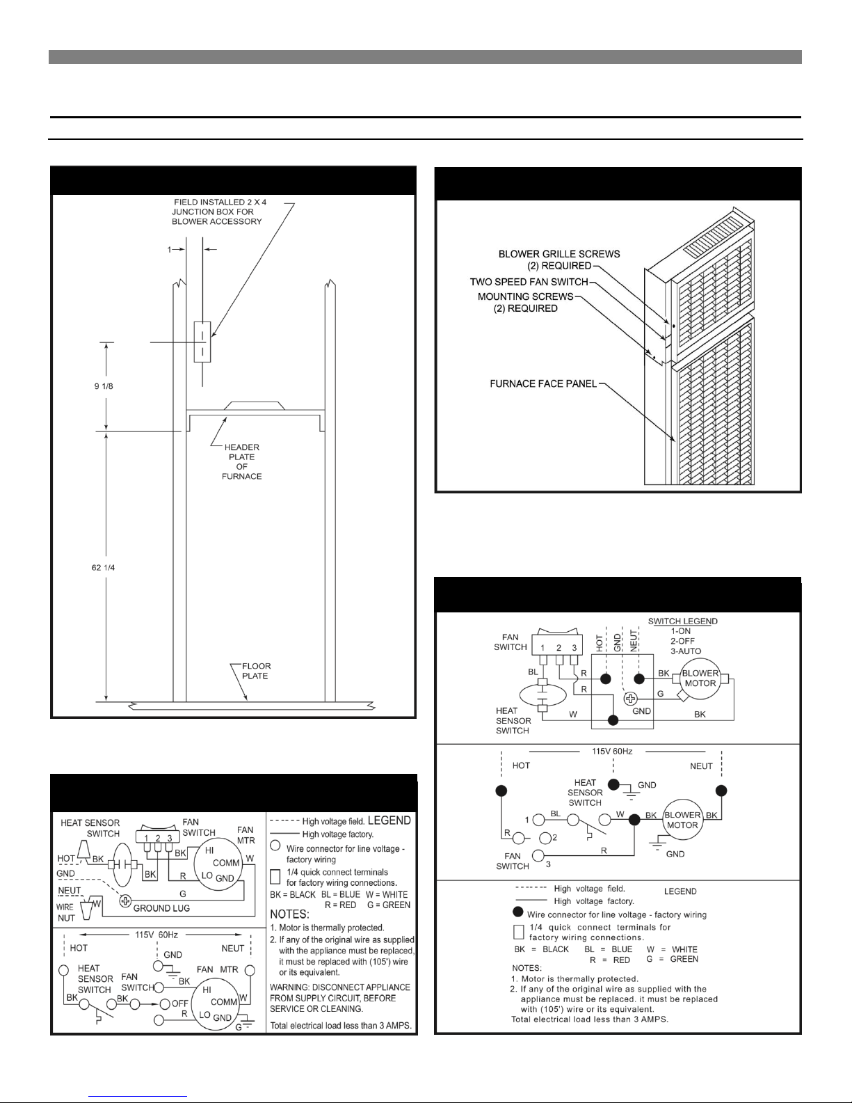
3. Install a 115V electrical outlet as shown in Figure A.
familiar with wiring codes in general, have a competent
electrician do this job.
Drill a 1/8-inch diameter hole in each side of the furnace
face panel through the holes located on the sides of the fan
cabinet. Secure the blower to the furnace with the two
screws provided.
10. Replace the junction box cover, securing it with the screws
previously removed
11. Replace the blower grille, securing it with the screws
previously removed.
12. Set the switch to the desired position. If left in “HI” or
“LOW” position during the summer months, the blower
could be activated by heat. If this is undesirable, set
the switch to the “OFF” position.
4. Remove the two (2) screws securing the blower grille and
remove the blower grille as shown in Figure B.
5. Remove the two (2) screws securing the junction box cover.
Remove the cover to gain access to the knockout located in
the junction box.
6. Locate the knockout and remove it using a hammer and
screwdriver. Use caution when handling sharp metal edges.
7. Place the blower body on furnace top as shown in Figure B.
8. Route 115V wiring into the junction box through the
knockout.
9. Make wiring connections inside the junction box as shown in
Figures C and D. Follow applicable local and national
electrical codes. All electrical work must conform to your
local codes and ordinances or in their absence, with
National Electrical Code, NFPA 70/ANSI. If you are not
Page 26
26
FIGURE D – Wiring for Model 2907
FIGURE C – Wiring for Model 2901
FIGURE A – Install Electrical Outlet
FIGURE B – Install Blower Body
Installing Your Blower Accessory
Blower Accessory 2901 and 2907 (continued)
Page 27
Accessories– 27
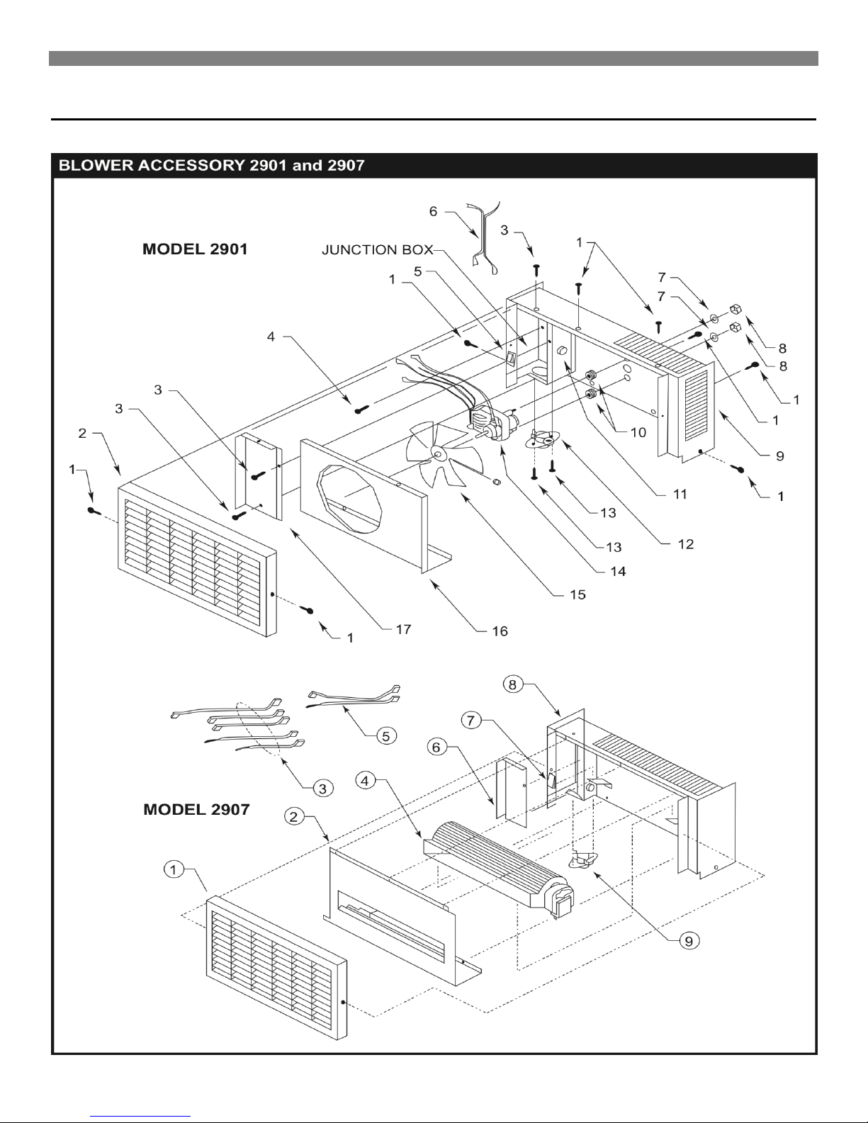
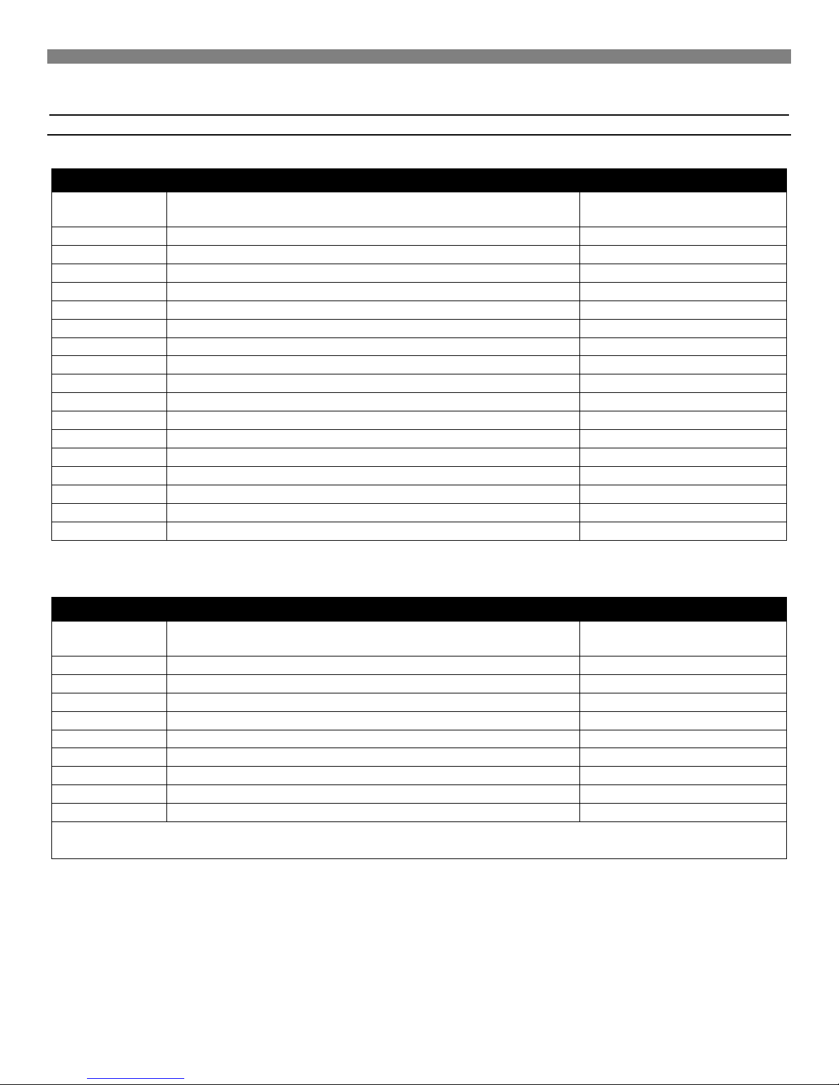
Blower Accessory Replacement Parts
Page 28
Care – 28
28
BLOWER ACCESSORY PARTS - MODEL 2901MODEL 2901
Ref.
No.
Description
Part
No.
1
Screw - #8Ax 3/8 (8)
P013200
2
Blower Grille
9C99
3
Screw - #8Ax 3/8 (8)
P093200
4
Screw - #10 x ½
P141000
5
Toggle Switch
P320911A
6
Wire Bridle
P320912 7 Flat Washer - #10-31 (2)
P127300 8 Machine Nut - #8-32 w/Washer (2)
P041100
9
Blower Body
9C102
10
Motor Mount Grommet (2)
P321078
11
Strain Relief Bushing
P012900
12
Fan Switch
P323095
13
Screw - #6-32 x 3/8”
P029200
14
Motor
P320905
15
Fan Blade
P320907
16
Orifice Plate
9D12-1
17
Junction Box Cover
9B161
BLOWER ACCESSORY PARTS – MODEL 2907MODEL 2907
Ref.
No.
Description
Part
No.
1
Blower Grille
9C99
2
Orifice Plate
9B246
3
Wire Assemblies
9B248
4
Blower and Motor
P323076 5 Heat Sensor Wire Assembly
P320912
6
Junction Box Cover
9A483
7
Fan Switch
P323080
8
Blower Body
9B249
9
Heat Sensor Switch
P323095
Use only manufacturer’s authorized parts.
NOTE: Nuts, bolts, screws, and washers are standard hardware items and may be purchased locally.
Blower Accessory Replacement Parts
Blower Accessory 2901 and 2907 (continued)
Page 29
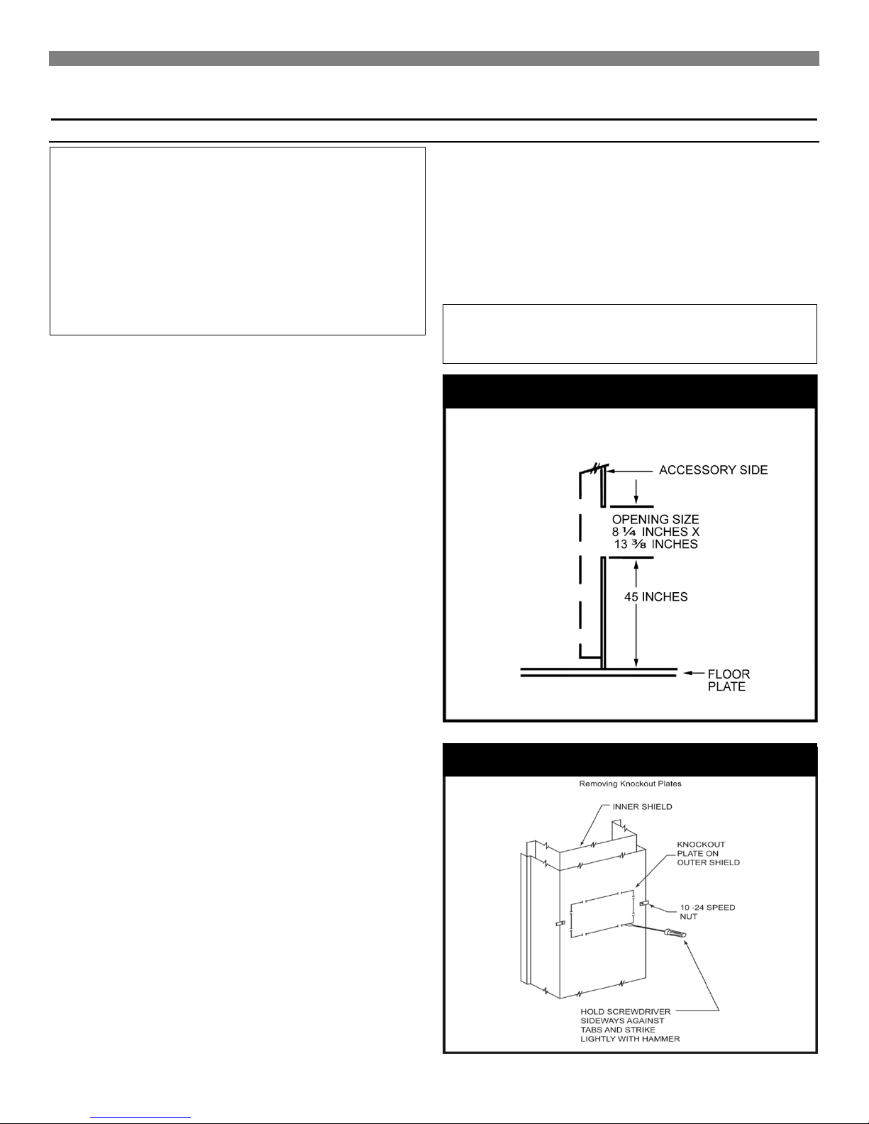
FIGURE B – Removing Knockout plates
FIGURE A- Recessed & Surface Installation
Installing Your Motorized Rear Outlet Accessory
Motorized Rear Outlet Register 6919 and 6920
WARNING: Danger of property damage, bodily injury or
death. Turn off all electrical power supply at disconnect switch,
fuse box or service panel before removing or working on fan.
For your protection against shock hazard, this appliance is
equipped with a three-prong (grounding) plug and should be
plugged directly into a properly grounded three-prong
receptacle. Do not cut or remove the prong. All electrical work
must conform to your local codes and ordinances or in their
absence, with National Electrical Code ANSI/NFPA 70. In
Canada, use the Canadian Electrical Code C22.1. If you are
not familiar with the wiring codes in general, have a competent
electrician do this job.
MOTORIZED REAR OUTLET REGISTER 6919 AND 6920
This Rear Outlet Register directs some of the heated air into the
room opposite the one in which the furnace is installed. Read
these instructions carefully and familiarize yourself with the
installation before you begin. Use gloves to protect your hands
from sharp metal edges.
BLOWER SETTINGS
You must select "ON" for continuous blower operation or "AUTO"
for automatic setting. If the blower is set on "AUTO" when the
furnace heats up, the heat sensor switch is activated and the
blower will operate until the furnace cools down, then the blower
will turn off. The blower will not operate if fan switch is set in the
"OFF" (center) position.
LOCATION WARNING
This register must be centered between studs and aligned with
the furnace for proper engagement. Make sure the furnace is
centered between the same studs before you cut any wall
openings for the register.
1. Measure and mark wall for opening as shown in Figure A.
Check the wall for any electrical wiring present before
cutting the opening. Reroute existing electrical if necessary.
4. Attach speed nuts to the outer shield (Figure B). After the
furnace is in position, insert the outlet register into the
opening as shown in Figures C, D and E. Install machine
screws through the register housing and into the speed nut
clips on the furnace outer shield. Do not over tighten the
screws.
5. After the register has been either wired, (Figure F), or
plugged in, set the fan switch to the desired blower
operation.
CAUTION: Do not install this kit where the outlet grille
may be blocked or covered by a door, curtains or any
other obstructions.
2. If recessed-mounted installation, place the plaster ground in
the opening and attach to the 2x4 studs.
3. An embossed knockout plate is located on the rear of the
outer shield and another is located directly behind it on the
inner shield. (Figure B). Remove the knockout plates on
the furnace by punching in the lower corners of the plate
with a screwdriver blade. Then, holding the screwdriver
blade sideways against the side and bottom connecting
tabs, strike the head of the screwdriver lightly with a
hammer to break the tabs. Swing the plate outward and
bend it back and forth to break the top tabs. Both knockout
plates must be removed in order to attach the register
assembly properly. If the inner shield knockout is not
embossed deep enough to be removed easily, mark an
outline using the existing opening as a guide. Use tin snips
to cut the area away. A pilot hole may be needed to begin
the first cut. Take care not to damage the combustion
chamber directly behind the inner shield when making a
pilot hole.
Page 30
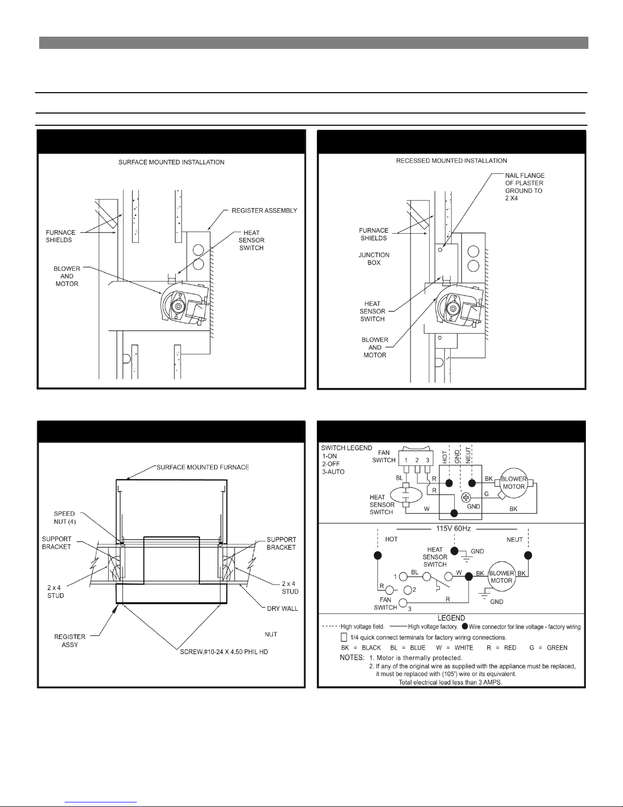
30
FIGURE C – Surfaced Mounted Installation
FIGURE D – Recessed Mounted Installation
FIGURE F - Wiring
FIGURE E – Surface Mounted Installation
Installing Your Motorized Rear Outlet Accessory
Motorized Rear Outlet Register 6919 and 6920 (continued)
Page 31
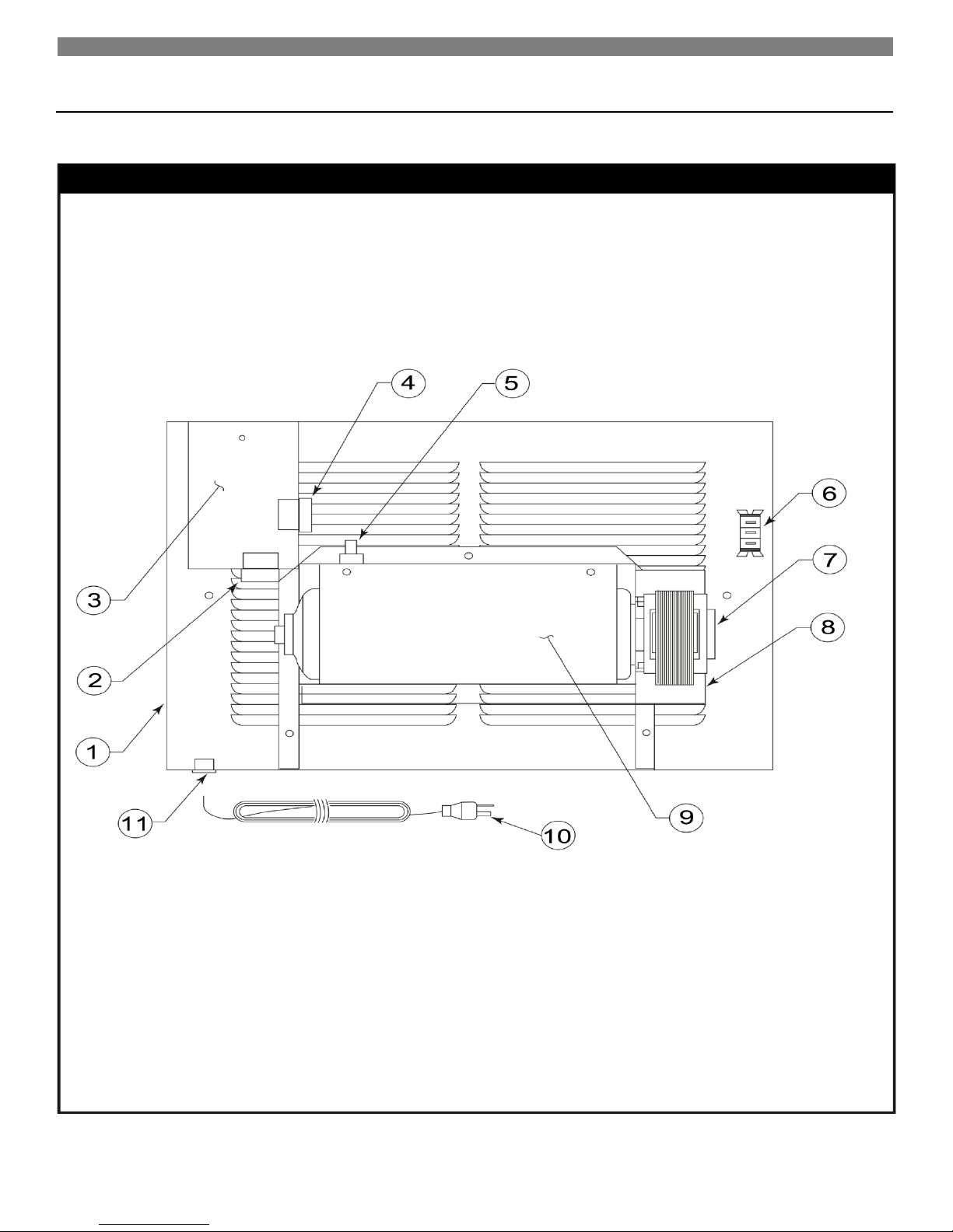
Motorized Rear Outlet Replacement Parts
Motorized Rear Outlet – Models 6919 and 6920
Page 32
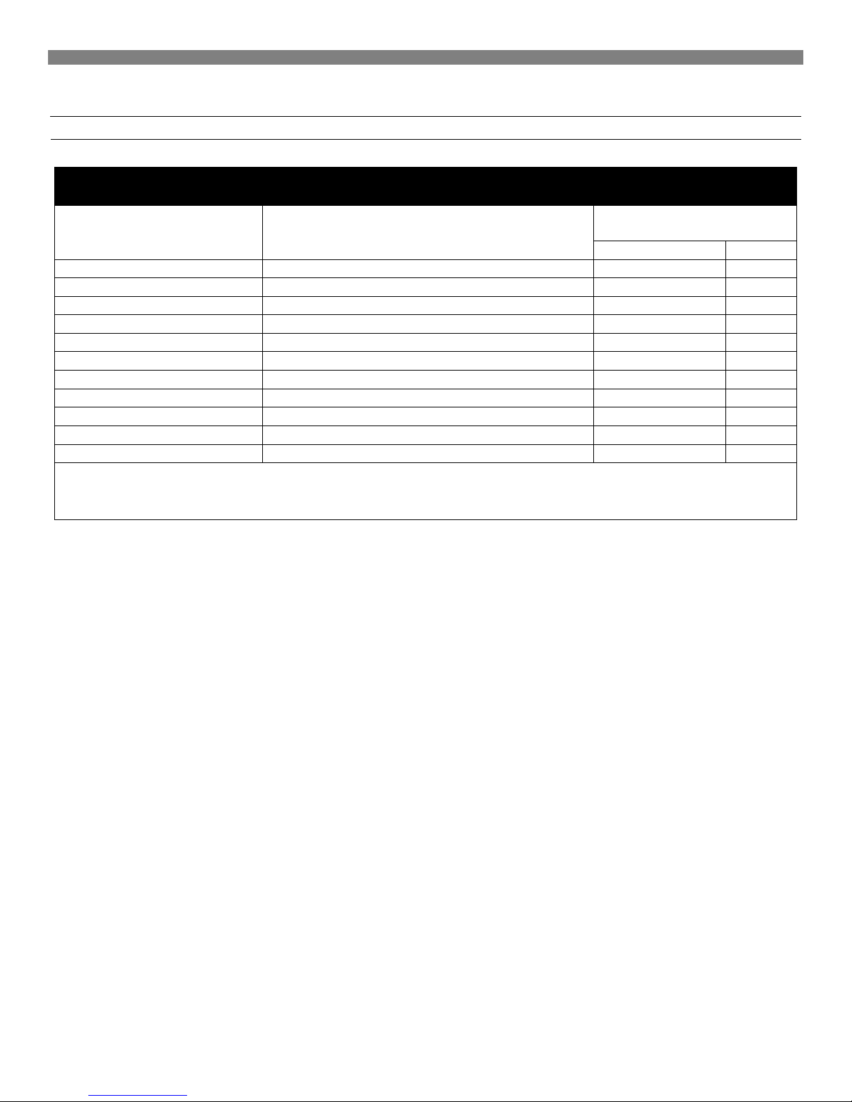
32
Motorized Rear Outlet Replacement Parts List – Models 6919 and 69206919 and 6920
Ref.
No.
Description
Part
No.
6919
6920
1
Register Assembly
9B269
PB285
2
Strain Relief Bushing
P500185
P500185
3
J-Box Cover
9A427
9A427
4
Strain Relief Bushing
P603108
P603108
5
Heat Sensor Switch
P323079
P323079
6
Fan Switch
P323080
P323080
7
Motor and Blower
P323076
P323076
8
Motor cover
9A432
PA462
9
Motor Housing Back Plate
9B266
9B284
10
Cord and Plug
P323081
P323081
11
Bushing
P323084
P323084
Use only manufacturer’s authorized parts.
NOTE: Nuts, bolts, screws, and washers are standard hardware items and may be purchased locally.
Motorized Rear Outlet Replacement Parts
Motorized Rear Outlet Replacement Parts (continued)
Page 33
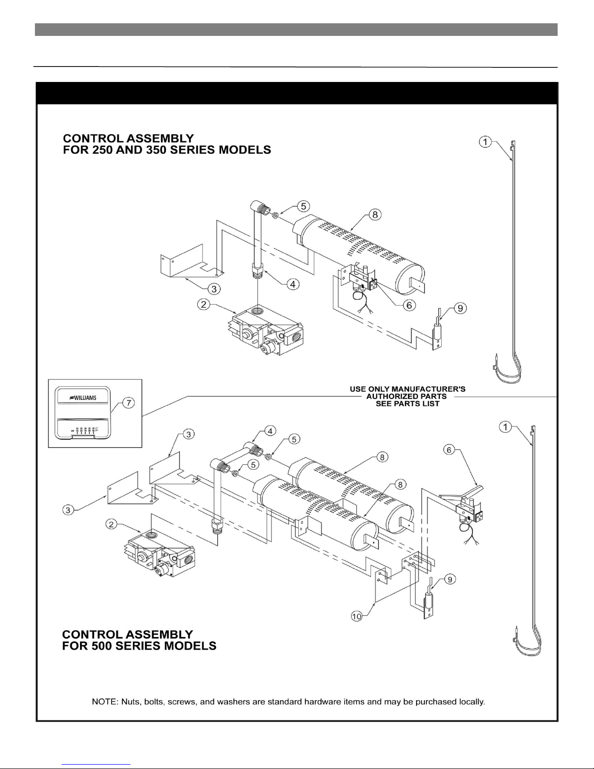
Furnace Replacement Parts
Control Assembly – 250, 350, and 500 Series
Page 34
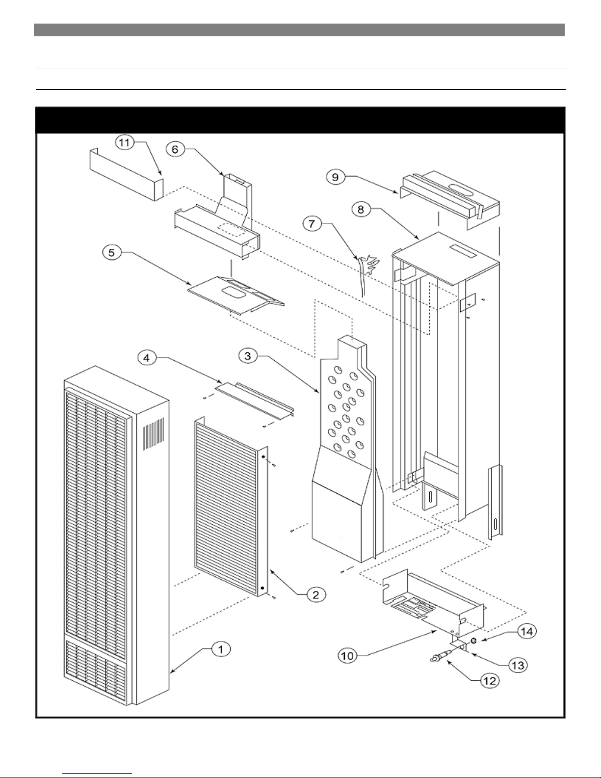
Furnace Replacement Parts
34
Cabinet and Body Parts - 250 and 350 Series
Furnace Replacement Parts (continued)
Page 35
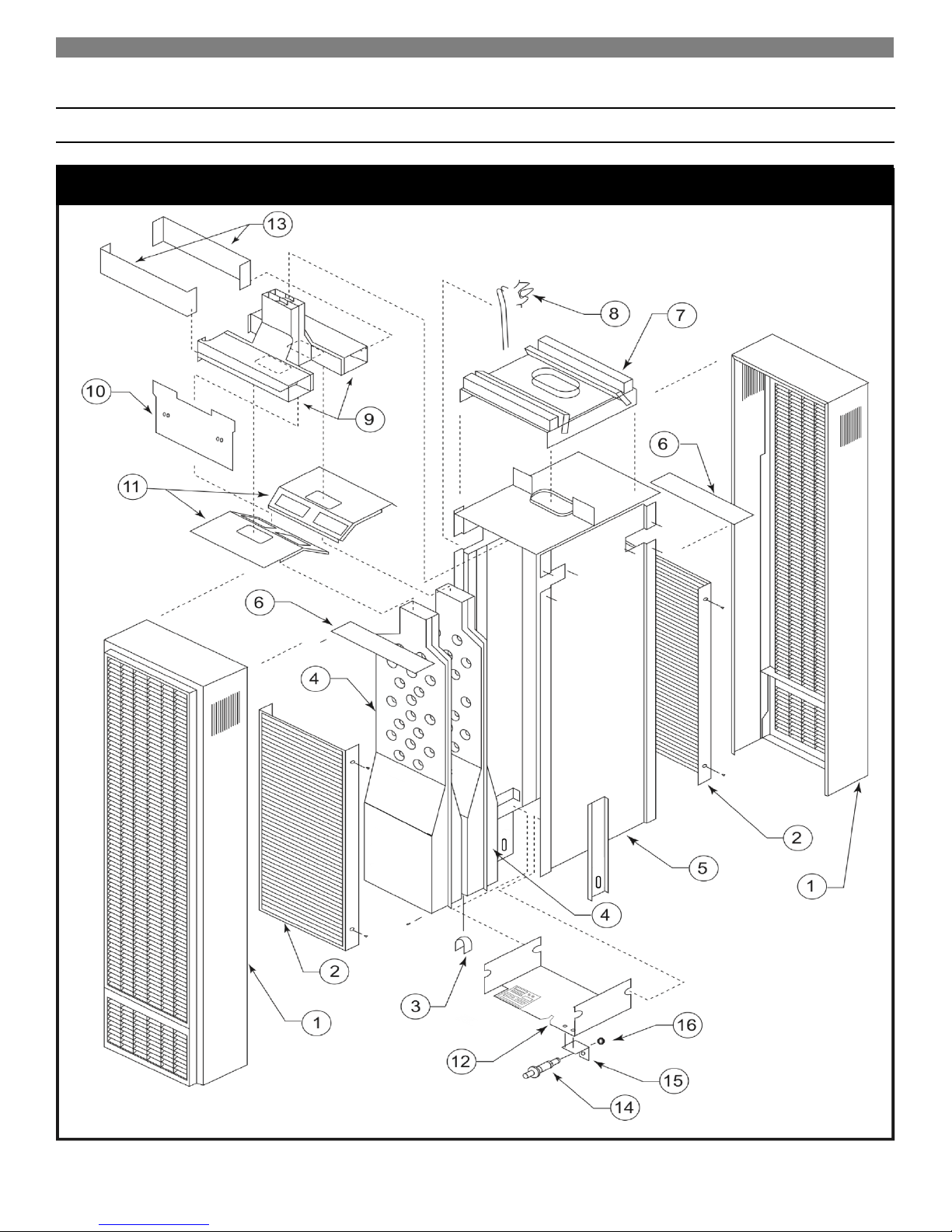
Furnace Replacement Parts
Cabinet and Body Parts – 500 Series
Furnace Replacement Parts (continued)
Page 36
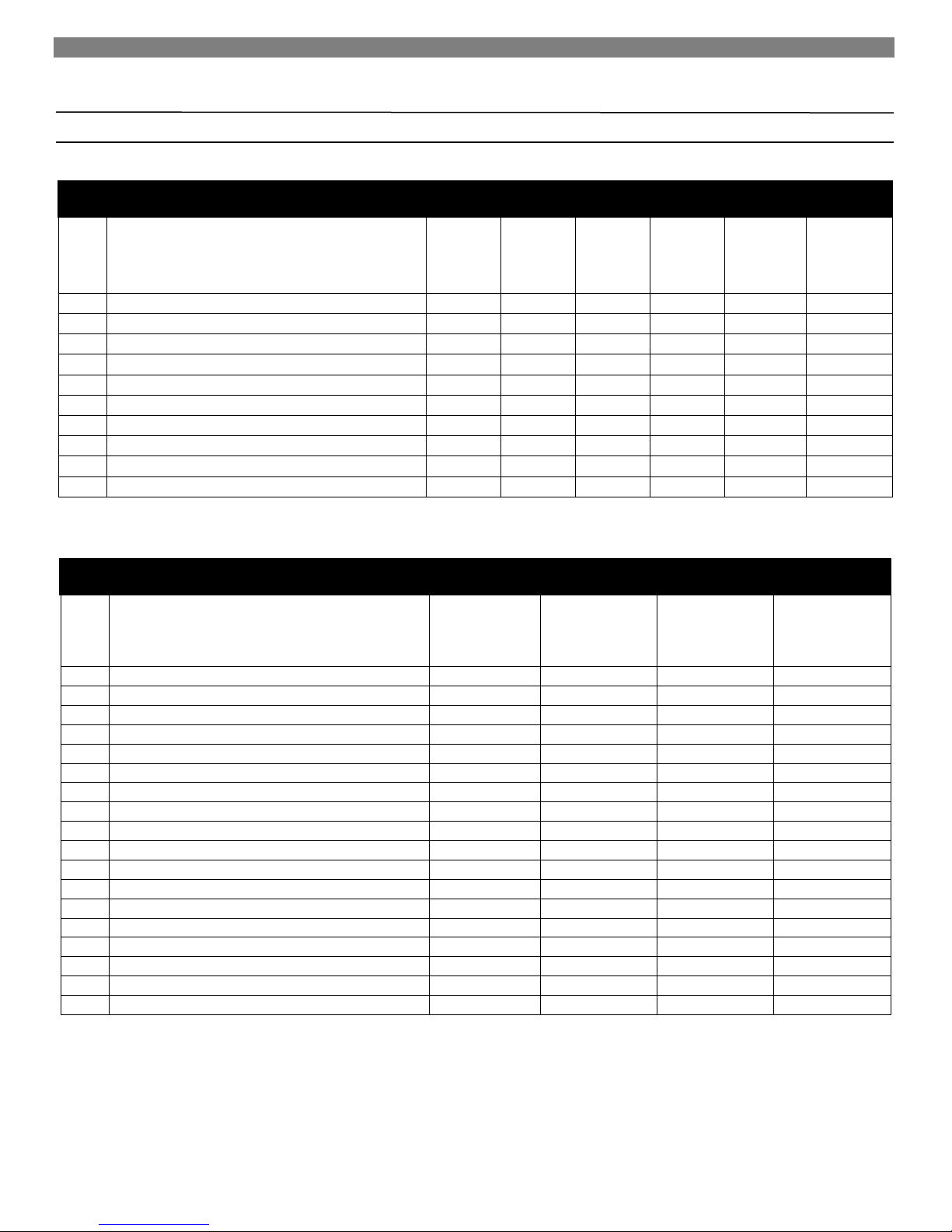
Furnace Replacement Parts
36
REF.
NO.
DESCRIPTION
2509621
2539621
2559621
2509622
2539622
2559622
3509621
3539621
3559621
3509622
3539622
3559622
5009621
5039621
5059621
5009622
5039622
5059622
1
Wire Assembly (2 Required for 500 Series)
P321836
P321836
P321836
P321836
P321836
P321836
2
Valve
P322660
P323011
P322660
P323011
P322660
P323011
3
Front Burner Bracket
9B234
9B234
9B234
9B234
9B243
9B243
4
Manifold
P323660
P323660
P323660
P323660
P323661
P323661
5
Burner Orifice (2 Required for 500 Series)
P090554
P090543
P090554
P090538
P090554
P090544
6
Pilot/Generator Assembly
P501618
P501617
P501618
P501617
P322397
P322396
7
Thermostat
P322016
P322016
P322016
P322016
P322016
P322016
8
Burner (2 Required for 500 Series)
P323648
P323648
P323648
P323648
P323648
P323648
9
Electrode
P322276
P322276
P322276
P322276
P322155
P322155
10
Pilot Mounting Plate
-
- - -
9A409
9A409
REF.
NO.
DESCRIPTION
2509621
2539621
2559621
2509622
2539622
2559622
3509621
3539621
3559621
3509622
3539622
3559622
1
Face Panel
4915
4915
4915
4915
2
Front Heat Shield
9C155
9C155
9C155
9C155 3 Combustion Chamber
6912
6912
6913
6913
4
Deflector
9B199
9B199
9B199
9B199 5 Inner Shield Top
9C153
9C153
9C153
9C153
6
Draft Hood
9C165
9C165
9C165
9C165 7 Vent Limit Switch
P321826
P321826
P322055
P322055
8
Shield Assembly
9C209
9C209
9C209
9C209
9
Header
5902
5902
5902
5902
10
Burner Pan
9B237
9B237
9B237
9B237
11
Heat Deflector
9A440
9A440
9A440
9A440
12
Manual Spark Igniter
P285500
P285500
P285500
P285500
13
Igniter Bracket
7A189
7A189
7A189
7A189
14
Pal Nut
P285501
P285501
P285501
P285501
**
Header - Insulation
P310000
P310000
P310000
P310000
**
Parts Bag
9A288-1
9A288-1
9A228-1
9A228-1
**
Knob
P332606
P332606
P332606
P332606
**
Vent Limit Switch Bracket
P322074
P322074
P332074
P332074
Control Assembly – 250, 350 & 500 Series
Cabinet and Body Parts - 250 & 350 Series
Furnace Replacement Parts (continued)
** Not Shown
Page 37
Furnace Replacement Parts
REF. NO.
DESCRIPTION
5009621
5039621
5059621
5009622
5039622
5059622
1
Face Panel (2 Required)
4915
4915
2
Front Heat Shield (2 Required)
9C155
9C155
3
Carryover Shell
9A321-1
9A321-1
4
Combustion Chamber (2 Required)
6914
6914
5
Shield Assembly
9C211
9C211
6
Deflector (2 Required)
9B199
9B199
7
Header
5901
5901
8
Vent Limit Switch
P321826
P321826
9
Draft Hood (2 Required)
9C170
9C170
10
Non-Vision Shield
9C157
9C157
11
Inner Shield Top (2 Required)
9C158
9C158
12
Burner Pan
9B244
9B244
13
Blower Heat Deflector
9A440
9A440
14
Manual Spark Igniter
P285500
P285500
15
Igniter Bracket
7A189
7A189
16
Pal Nut
P285501
P285501
**
Header – Insulation
P310000
P310000
**
Parts Bag
9A288-1
9A288-1
**
Knob
P332606
P332606
**
Vent Limit Switch Bracket
P322074
P322074
Cabinet and Body Parts – 500 Series
Furnace Replacement Parts (continued)
** Not Shown
Page 38
Troubleshooting Your Furnace
38
SYMPTOM
POSSIBLE CAUSE(S)
CORRECTIVE ACTION
1. Pilot will not stay
lit after following
lighting
instructions.
a. Generator producing
insufficient millivolts.
b. Loose or dirty generator
connections at gas valve.
c. Generator defective.
d. Grounded thermostat wire.
e. Defective gas valve.
a. Check pilot flame. It must impinge on the generator.
b. Clean and/or tighten generator connections at valve.
c. Check generator with millivolt meter. Take reading at generator
terminals of the valve with the valve placed in “Pilot” position.
Disconnect the thermostat wires. The millivolt reading should be
450 millivolts or more.
d. Remove thermostat wires from valve terminals. If pilot now stays lit,
trace thermostat wiring circuit for a ground. May be grounded to
furnace, gas supply, nails or staples.
e. Replace gas valve after above is verified.
2. No gas to the
main burner.
a. Gas valve not turned to the
“ON” position after lighting
pilot.
b. Thermostat not tuned to a
position calling for heat.
c. Plugged furnace orifice.
d. Improper wired or broken
thermostat wires. Defective
thermostat.
e. Pilot generator may not be
generating sufficient
millivolts to open valve.
f. Defective valve.
g. Vent safety switch tripped.
a. Turn gas valve knob to the “ON.”
b. Set thermostat to a position calling for heat.
c. Checkclean or replace.
d. Check connections at valve terminals. If valve operates, check
thermostat wires.
e. See 1a and 1c above.
f. Replace gas valve after above is verified.
g. Check and reset.
3. Furnace
operates but
turns off before
room
temperature is
attained.
a. Thermostat location.
b. Defective thermostat.
a. Check thermostat location. It should not be in the path of warm air
discharge from furnace, near a lamp or above a T.V. or stereo unit.
b. Check thermostat calibration or replace.
4.
Furnace not
producing
sufficient heat.
a. Furnace may be too small for
space being heated.
b. Furnace not burning at full
rate.
a. Check heat sizing calculations.
b. Check for low gas pressure at gas valve. It should be 4 inches
water column for natural gas; 10-inches water column for L.P.G.
Check for blocked burner orifices.
5. Furnace
operates but will
not shut off
when room
temperature is
attained.
a. Thermostat wiring defective.
b. Thermostat location.
c. Defective thermostat.
d. Valve stuck open.
a. Thermostat lead wires may be shorted together, caused by a nail or
staple. Check by removing thermostat leads from valve terminals.
b. Check thermostat location. If on an outside wall, or there is a hole
in the wall behind the thermostat, cold air may be coming in contact
with the thermostat. Relocate.
c. Check thermostat calibration; verify thermostat temperature
reading; or replace.
d. Replace valve.
Page 39
Troubleshooting Your Furnace
SYMPTOM
POSSIBLE CAUSE(S)
CORRECTIVE ACTION
6. Pilot outage.
a. Pilot flame may be low or
blowing (high).
b. Drafts or drafty areas.
a. Adjust pilot flame. Pilot orifice may be plugged (check for spider
webs or other material).
b. Check for doorway and high movement areas.
7. Noisy blower.
a. Housing rattling.
b. Blower dirty.
c. Blower wheel bent.
a. Tighten blower screws.
b. Clean blower wheel.
c. Straighten or replace.
8. Blower does not
run.
a. Fan switch not set.
a. Select fan speed.
9. Main burner will
not stay on.
a. Blockage in vent pipe.
b. Vent too short.
c. Restriction in vent system
caused by offsets.
d. Incorrect vent pipe.
e. Loose connections on the
vent safety wiring harness.
a. Check vent pipe for blockage, such as bird nests, twigs, leaves, etc.
Check that the vent cap is properly installed, and not placed too far
down on the vent pipe. Cap must be the same manufacturer as the
vent.
b. The vent should terminate a minimum of 12 feet above the floor
plate. The top of the vent must be at least 2 feet above any
obstacle within a 10 foot radius, including the roof.
c. All type “B” vents shall extend in a vertical direction with offsets not
exceeding 45 degrees. Any angle greater than 45 degrees from
vertical is considered horizontal. Any offsets used should be a
minimum of 2-feet above the draft hood or as far away as possible
to allow venting to begin before any restriction is encountered. The
use of too many offsets may also prevent proper venting.
d. Use listed B/W type vent pipe. DO NOT use transite or any other
type of ceramic pipe for venting. DO NOT use single wall vent pipe.
When venting into a masonry chimney, the chimney must be
properly lined and sized for this gas furnace. The use of type “B” or
flexible chimney liner is recommended.
e. Check the connection on both the switch and the gas valve. Tighten
if necessary.
10. Abnormal
operation.
a. Delayed ignition. Pilot flame
may be too low.
b. Expansion noise, ticking.
c. Combustible gas spillage.
d. Excessive flame roll-out.
e. Burner is over-fired.
f. Yellow burner flame.
g. Yellow pilot flame.
h. Expansion noise
a. Adjust pilot flame. Refer to “How to Care for Your Furnace” section
in this manual.
b. Check installation. Casing may be distorted by being fastened to an
uneven opening or jammed under the header. A restricted vent may
create expansion noise. Refer to “Vent Installation” section in this
manual.
c. Check vent system for a blocked flue, excessive down draft (wind)
or negative pressure in room caused by a ventilating fan or a fire in
a fireplace.
d. Furnace is possibly overrated, check for high gas pressure at gas
valve. (See 4B).
e. Check the manifold gas pressure. Check the rate, this appliance is
manufactured for elevations up to 4,500 feet. It must be derated for
operation above 4,500 feet.
f. Check burner for obstructions. Install new burner and pilot orifices.
g. Remove pilot orifice, check and clean.
h. DO NOT elevate the furnace off the floor unless supported by the
free standing accessory. Never shear the legs. If replacing the
furnace, bring the vent pipe to the header. DO NOT raise the
furnace to the vent pipe. Legs must be flat on the floor plate, never
one in front of the other.
Troubleshooting Your Furnace (continued)
Page 40
Hints and Information
40
WARNING: If the information in this manual is
not followed exactly, a fire or explosion may
result causing property damage, personal
injury or loss of life.
Williams Furnace Company • 250 West Laurel Street, Colton, CA 92324
Manufactured in the U.S.A. • Established 1916
DO NOT store or use gasoline or other
flammable vapors and liquids in the vicinity or
this or any other appliance.
WHAT TO DO IF YOU SMELL GAS
a neighbor’s phone. If you cannot reach
P322085 - APRIL 2012
Service Hints
If your furnace fails to work correctly, you may avoid the
inconvenience and cost of a service call by checking the
troubleshooting section on pages 38 and 39 before you call
for service.
How to Order Repair Parts
When ordering repair parts, always give the following Information:
1. MODEL NUMBER
Open all of the windows.
Do not try to light any appliance.
Do not touch any electrical switch.
Do not use any phone or cell phone in
your building.
Extinguish any open flame.
Immediately call your gas supplier from
your gas supplier, call the fire
department.
Installation and service must be performed by
a qualified installer, service agency or the gas
supplier.
2. MFG. DATE CODE
3. PART NUMBER
4. PART DESCRIPTION
All parts listed herein may be ordered from your equipment
supplier. The Model Number of your Williams wall furnace will be
found on the nameplate near gas valve, inside control
compartment.
(909) 825-0993 • FAX: (909) 824-8009 www.wfc-fc.com
ALL RIGHTS RESERVED
 Loading...