

Williams 1403621.05, 3003621.05 Owner's Manual
owner's manual
MODEL NOS:
1403621.05
3003621.05
INSTALLATION & OPERATING INSTRUCTION MANUAL
DIRECT VENT
FU RNACE FoRMANUFAOTOREO/MOB,,EI
HOME APPLICATIONS
READ THIS OWNERS
MANUAL CAREFULLY
BEFORE YOU INSTALL
YOUR NEW WILLIAMS
WALL FURNACE
• Unpacking
• Installation
• Operation
• Repair Parts
WARNING: Improper installation, adjust-
ment, alteration, service or maintenance
can cause injury or property damage.
Refer to this manual. For assistance or
additional information consult a qualified
installer, service agency or the gas
supplier.
WARNING: If the information in this
manual is not followed exactly, a fire or ex-
plosion may result causing property
damage, personal injury or loss of life.
Do not store or use gasoline or other flam-
mable vapors and liquids in the vicinity
of this or any other appliance.
WHAT TO DO IF YOU SMELL GAS
• Open all windows.
• Do not try to light any appliance.
• Do not touch any electrical switch; do
not use any phone in your building.
• Extinguish any open flame.
• Immediately call your gas supplier from
a neighbor's phone. Follow the gas
supplier's instruction.
• If you cannot reach your gas supplier,
call the fire department.
Installation and service must be per-
formed by a qualified installer, survice
agency or the gas supplier.
WILLIAMS Furnace Co., 225 Acacia St., Colton, CA 92324
PRINTED IN USA 7/_8 P322874
Contents
Your Warranty .............................................................. 2
Introductioin .................................................................. 3
Basic Description ......................................................... 3
Optional Accesories ..................................................... 3
Helpful Installation Information ...................................... 3
Safety Rules ................................................................. 4
Unpack Your Furnace ................................................... 5
Basic Tools Needed ..................................................... 5
Basic Materials ............................................................. 5
Installing Your Wall Furnace .......................................... 5
Locating Wall Furnace and Thermostat ..................... 6-7
Installation ................................................................. 7-9
Optional Blower Installation .......................................... 9
Gas Supply and Piping ........................................... 10-11
Thermostst Installation .......................................... 11-12
Thermostat Connection at Gas Valve ........................ 12
Furnace Technical Information .................................. 13
Cabinet Installation ............................................... 13-14
Start Up Procedure ................................................. 14-15
Operating Your Furnace ............................................. 15
Safety, Operating and Shutdown Instructions ............ 16
Gas Conversion .......................................................... 17
How To Care For Your Furnace .................................. 18
Trouble Shooting .................................................... 19-20
Repair Parts ........................................................... 21-24
Service Hints ................................................ Back Cover
How To Order Repair Parts .......................... Back Cover
Your Warranty
The Manufacturer, Williams Furnace CO, warrants this wall furnace or healer to Ihe original purchaser under the following conditions:
LIMITED ONE-YEAR WARRANTY
1 Any part thereof which proves to be defective in material or workmanship within one year from date of original purchase for use will be repaired or replaced at the
Manufacturer's option, FOB its factory
2 NO fiability is assumed by the Manufacturer for removal or installation labor costs, nor for freight or delivery charges
LIMITED EXTENDED WARRANTY
1. _n addition to the above limited one-year warranty on the complete unit, any heat exchanger which burns out or rusts under normal instaflafion, use and service
conditions during a period of nine years following expiration of the one-year warranty period will be exchanged for a like or functionally similar part, FOB Manufac-
turer's factory.
2. No liability is assumed by the Manufacturer for removal or installation labor costs, nor for freight or delivery charges.
LIMITATIONS
1. THIS LIMITED WARRANTY IS THE ONLY WARRANTY MADE BY THE MANUFACTURER IMPLIED WARRANTIES OF MERCHANTABILITY OR F_TNESS FOR
ANY PARTICULAR PURPOSE ARE LIMITED TO THE SAME ONE YEAR TERM AS THIS EXPRESS WARRANTY. UNDER NO CIRCUMSTANCES SHALL THE
MANUFACTURER BE LIABLE FOR INCIDENTAL, CONSEQUENTIAL, SPECIAL OR CONTINGENT DAMAGES OR EXPENSES ARISING DIRECTLY OR INDIRECT-
LY FROM ANY DEFECT IN THE PRODUCT OR ANY COMPONENT OR FROM THE USE THEREO!: THE REMEDIES SET FORTH HEREIN ARE THE EXCLUSIVE
REMEDIES AVAILABLE TO THE USER AND ARE IN LIEU OF ALL OTHER REMEDIES
Some states do not allow limitations on how long an impfled warranty _asts, and some states do not allow the exclusion or limitation of incidental
or consequential damages, so the above limitations or exclusions may not apply to you
2 This warranty does not include any charge for labor or installation.
3. This warranty does not extend to painted surfaces nor to damage or defects resulting from accident, alteration, misuse or abuse, or improper ststaflation.
4. This warranty does not cover claims which do not involve defective workmanship or malerials
DUTIES OF THE CONSUMER
1 The heating equipment must be instalted by a qualified installer and operated in accordance with the installation and homeowner*s instrucbons furnished with the
equtpment
2 Any travel, diagnostic costs, service labor, and labor to repair the defective unit will be the responsibility of the owner.
3. A bill of sale, cancelled check, payment record or permit should be kept to verify purchase date to establish the warranty period
4 Have the installer enter the requested information in the space below.
GENERAL
1. The Manufacturer neither assumes nor authorizes any person to assume for it any other obligation or liability in connection with said equipment.
2. Service under this warranty should be obtained by contacting your dealer Provide the dealer with the model number, serial number and purchase date verification
3. g, within a reasonable time after contacting your dealer, satisfactory service has nol been received, contact: Customer Service Department, 225 Acacia St., Colton,
CA 92324, for assistance.
4. THIS WARRANTY GIVES YOU SPECIFIC LEGAL RIGHTS, AND YOU MAY ALSO HAVE OTHER RIGHTS WHICH VARY FROM STATE TO STATE.
INSTALLATION INFORMATION
Model No.
Serial No.
Orig. Purchaser.
Address
City and State_ Zip
Dealer
Address
City and State_ Zip
Installation date Signed by .(Dealer or
authorized representative who certifies that this appliance has been installed in accordance with Manufacturer's instructions and
local codes.)
--2--
Introduction
Please read our instructions before you install and use your furnace. This will help you obtain the full value from this
furnace. It could help you avoid needless service costs, if the answer to the problem is found within this instruction
manual.
Basic Description
Your direct vent wall furnace is shipped ready to install
against an exterior wall up to 9 inches thick. For walls
greater than 9 inches, and up to 24 inches thick, use an
optional VENT EXTENSION KIT listed under OPTIONAL
ACCESSORIES.
The furnace may burn either Natural or LP. Gas, depend-
ing on the model you have purchased.
No electric power is required unless furnace is equipped
with an optional blower accessory.
Always consult your local heating or plumbing inspector,
building department or gas utility company regarding
regulations, codes or ordinances which apply to the in-
stallation of a direct vent furnace.
The sealed combustion system draws combustion air
directly from outdoors into the combustion chamber and
combustion gases are discharged directly to the outdoors
through tubes mounted to the rear of the furnace.
The furnace heat exchanger is built of heavy gauge steel
treated for corrosion resistance.
The furnace cabinet is also constructed of heavy gauge
steel and has an enamel paint finish.
The furnace controls are located behind an access door
on the lower front of the furnace. All models are equipped
with American Gas Association and Canadian Gas
Association listed gas valves and pilots.
MODELS 1403611, 1403612, 2203611, 2203612, 3003611
and 3003612 are equipped with a built-in thermostat.
MODELS 1403621, 1403622, 2203621, 2203622, 3003621
and 3003622 are equipped with a wall thermostat.
Optional Accessories
ALL MODELS
For walls less than 41/2inches thick, a thin Wall Collar Kit
9307 may be used to increase wall thickness if wood strips
are undesirable.
MODEL: 3003621,05
To increase circulation of warmed air within the heated
space, you may use Blower Accessory Kit 2302, which is
equipped with a two-speed fan and automatic fan switch.
ALL MODELS:
For additional vent cap protection, Vent Cap Guard 9308
may be used. This mounts to the outside of the exterior
wall over the vent cap.
MODEL: 1403621.05
For walls greater than 9 inches thick and up to 24 inches
thick, use one of the following Vent Extension Kits:
KIT NUMBER WALL THICKNESS
9304 9 inches to 15 inches
9303 15 inches to 24 inches
NOTE
Accessories are identified on the carton by their manufac-
turing number. (For example: 9301; 9302; 9303.) These
manufacturing numbers are also listed on the furnace
rating plate so you can be sure you have the accessory
that fits your furnace.
MODEL: 3003621.05
For walls greater than 9 inches thick and up to 24 inches
thick, use one of the following Vent Extension Kits:
KIT NUMBER WALL THICKNESS
9301 9 inches to 15 inches
9303 15 inches to 24 inches
(140 (or) 300 model series)
--3--
Safety Rules
WARNING
READ THESE RULES AND THE INSTRUCTIONS
CAREFULLY. FAILURE TO FOLLOW THESE
RULES AND INSTRUCTIONS COULD CAUSE A
MALFUNCTION OF THE FURNACE. THIS COULD
RESULT IN DEATH, SERIOUS BODILY INJURY,
AND/OR PROPERTY DAMAGE.
7.
umn. The maximum inlet gas supply pressure is 13"
water column.
ANY SAFETY SCREEN, GUARD OR PARTS RE-
MOVED FOR SERVICING AN APPLIANCE MUST BE
REPLACED PRIOR TO OPERATING THE AP-
PLIANCE TO AVOID PROPERTY DAMAGE, BODILY
INJURY OR DEATH.
INSTALLATION MUST CONFORM TO LOCAL CODES. IN
THE ABSENCE OF LOCAL CODES, INSTALLATION MUST
CONFORM WITH THE NATIONAL FUEL GAS CODE, ANSI
Z223.1. THE APPLIANCE, WHEN INSTALLED, MUST BE
ELECTRICALLY CONNECTED AND GROUNDED IN
ACCORDANCE WITH LOCAL CODES OR, IN THE
ABSENCE OF LOCAL CODES, WITH THE CURRENT
NATIONAL ELECTRICAL CODE ANSI/NFPA NO. 70.
IN CANADA
1. INSTALLATION MUST CONFORM TO LOCAL
CODES OR, IN THE ABSENCE OF LOCAL
CODES, THE CURRENT CANICGA B149 IN-
STALLATION CODE.
2. THE APPLIANCE, WHEN INSTALLED, MUST BE
ELECTRICALLY CONNECTED AND GROUND-
ED IN ACCORDANCE WITH LOCAL CODES OR,
IN THE ABSENCE OF LOCAL CODES, WITH
THE CURRENT CSA C22.1 CANADIAN ELEC-
TRICAL CODE.
3. REFERENCE IS MADE IN THIS MANUAL
REGARDING GAS TYPE AS L.PG. BE ADVISED
THAT LP.G. IS NOT AVAILABLE IN CANADA,
REFER TO PROPANE/L.I_ GAS.
8,
9,
10.
11.
12.
13.
14.
15.
INSTALL the furnace vent directly to the outdoors, so
that harmful gasses will not collect inside the building.
Follow the venting instructions for your type installa-
tion exactly. Use only the type and size of vent pipe
and fittings specified.
BE SURE to provide for adequate combustion and
ventilation air. See page 7. The flow of this air to the
furnace must not be blocked.
NEVER vent flue gases into another room, a fireplace
or any space inside a building. This could cause pro-
petty damage, bodily injury or death.
NEVER test for gas leaks with an open flame. Use
soap suds to check all gas connections. This will avoid
the possibility of fire or explosion.
ALLOW furnace to cool before servicing. Always shut
off electricity and gas to furnace when working on it.
This will prevent any electrical shocks or burns.
DUE TO HIGH TEMPERATURES, locate the furnace
out of traffic and away from furniture and draperies.
ALERT children and adults to the hazards of high sur-
face temperature and to keep away to avoid burns or
clothing ignition.
CAREFULLY supervise young children when they are
in the same room with the furnace.
1. USE ONLY MANUFACTURER'S REPLACEMENT
PARTS. USE OF ANY OTHER PARTS COULD
CAUSE INJURY OR DEATH.
2. DO NOT install this furnace in an alcove.
3. DO NOT install these furnaces in a travel trailer or
recreational vehicle.
4. MAINTAIN all clearances specified in section "Lo-
cating Wall Furnace and Thermostat" and "Vent In-
stallation".
5. Furnace must be equipped for proper type of gas
being used. (L.P. Gas or NAT. Gas). This furnace
is factory equipped for LP. Gas. If conversion is re-
quired, this must be done by a qualified service per-
son. Follow closely conversion instructions outlined
in this manual and on rating plate.
6. For Natural gas, the minimum inlet gas supply pres-
sure for the purpose of input adjustment is 5" col-
umn. The maximum inlet gas supply pressure is 7"
water column.
For L.P. gas, the minimum inlet gas supply pressure
for the purpose of input adjustment is11°water col-
16.
17.
18.
19.
20.
DO NOT place clothing or other flammable material
on or near furnace.
INSTALLATION and REPAIR must be done by a quali-
fied service person. The appliance should be inspected
before use and at least annually by a professional serv-
ice person. More frequent cleaning may be required
due to excessive lint from carpeting, bedding material,
etc. It is imperative that control compartments, burners
and circulating air passages be kept clean.
BEFORE INSTALLING: To avoid electrical shock, turn
off electrical circuits that pass through the wall where
you are going to install the furnace.
BE AWARE of good safety practices by wearing per-
sonal protective equipment such as gloves and safe-
ty glasses to avoid being injured by sharp metal edges
in or around furnace and while cutting or drilling holes
in wood and or sheet metal.
CAUTION: Label all wires prior to disconnection when
servicing controls. Wiring errors can cause improper
and dangerous operation. Verify proper operation after
servicing.
WARNING
DO NOT USE THIS HEATER IF ANY PART HAS BEEN UNDER WATER. IMMEDIATELY CALL A QUALIFIED
SERVICE TECHNICIAN TO INSPECT THE HEATER AND TO REPLACE ANY PART OF THE CONTROL SYSTEM
AND ANY GAS CONTROL WHICH HAS BEEN UNDER WATER.
,,_4__
Unpack Your Furnace
This direct-vent furnace is packaged complete including
the vent cap, vent tube and air inlet tube ready for instal-
lation on an exterior wall with a total thickness of from
5 inches minimum to a maximum of 9 inches.
Open the carton and remove all parts.
Examine all packing material carefully, Look for loose parts
before discarding. Store all parts where they cannot be
lost or damaged before you need them.
NOTE:
Check the burner rating plate located in burner compart-
ment, to make sure your furnace is equipped to operate
on the gas available (either NATURAL or L.P. GAS).
Convert for your field requirement. Furnace must match
gas usage exactly.
Basic Tools Needed
Hand drill or properly grounded electric drill
Expansion bit 1/2" to 1-5/8" or 1/2" or 1-1/2" blade bits
1/8" and 3/16" drill bit (metal)
6 ft. folding rule or tape measure
Screwdriver (Phillips head)
Pliers (wire cutting)
Hammer
Stud tocator or small finish nails
Tin snips
8" adjustable wrench
12" adjustable wrench
Key hole saw or Sabre saw
Hack saw
2 - 10" or 12" pipe wrenches
Gloves and safety glasses
Basic Materials
Pipe and fittings to make connections to furnace (see
page 10).
Caulking compound - silicone rubber with a temperature
rating of 500°E
Do not use types advertised as paintable or for bath tub
use as most contain fillers and will not withstand high
temperatures.
Pipe joint compound resistant to EFt Gases.
Electrical wiring supplies as needed for optional blower
if equipped (see page 9).
Minimum wire size is #14 gauge copper.
Installing Your Wall Furnace
The following steps are needed for proper installation and
safe operation of your furnace. If you have any doubts as
to any requirements, check with local authorities for local
and state codes affecting the installation.
Obtain professional help where needed.
DO NOT install these furnaces in a travel trailer, recrea-
tional vehicle.
IMPORTANT
For satisfactory and trouble-free operation be sure to:
1. Properly locate the furnace within the space to be
heated.
2. Provide for adequate combustion air around vent cap
on outside, see Fig. 1, page 6 and adequate air circula-
tion around cabinet inside the open room, see Fig. 2,
page 6.
3. Maintain all minimum clearances on pages 6 and 7
which apply to your furnace model.
Helpful Installation Information
The following booklets will help you in making the installa-
tion. Check at the library or they may be purchased from
the source listed below.
ANSI/NFPA 70 current edition "National Electrical Code."
In Canada: C22.1 Canadian Electrical Code.
American National Standard Z223.1 current edition "Na-
tional Fuel Gas Code."
In Canada: CAN/CGA-B149.1 (.2) Canadian Standard.
Obtain from - American National Standards Institute, Inc.,
1430 Broadway, New York, NY 10018.
--5 m
Locating Wall Furnace
Consider the following points before attempting to install
the furnace:
ALL MODELS
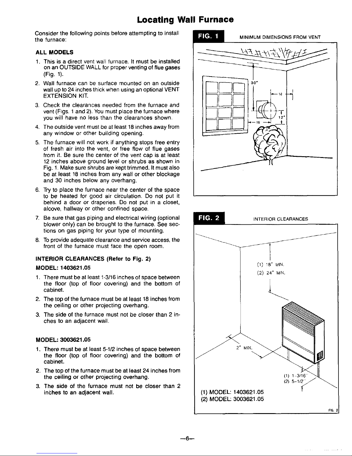
1. This is a direct vent wall furnace. It must be installed
on an OUTSIDE WALL for proper venting of flue gases
(Fig. 1).
2. Wall furnace can be surface mounted on an outside
wall up to 24 inches thick when using an optional VENT
EXTENSION KIT.
3. Check the clearances needed from the furnace and
vent (Figs. 1 and 2). You must place the furnace where
you will have no less than the clearances shown.
4. The outside vent must be at least 18 inches away from
any window or other building opening.
5. The furnace will not work if anything stops free entry
of fresh air into the vent, or free flow of flue gases
from it. Be sure the center of the vent cap is at least
12 inches above ground level or shrubs as shown in
Fig. 1. Make sure shrubs are kept trimmed. It must also
be at least 18 inches from any wall or other blockage
and 30 inches below any overhang.
6. Try to place the furnace near the center of the space
to be heated for good air circulation. Do not put it
behind a door or draperies. Do not put in a closet,
alcove, hallway or other confined space.
7. Be sure that gas piping and electrical wiring (optional
blower only) can be brought to the furnace. See sec-
tions on gas piping for your type of mounting.
8. To provide adequate clearance and service access, the
front of the furnace must face the open room.
INTERIOR CLEARANCES (Refer to Fig. 2)
MODEL: 1403621.05
1. There must be at least 1-3/16 inches of space between
the floor (top of floor covering) and the bottom of
cabinet.
2. The top of the furnace must be at least 18 inches from
the ceiling or other projecting overhang.
3. The side of the furnace must not be closer than 2 in-
ches to an adjacent wail.
MODEL: 3003621.05
1. There must be at least 5-1/2 inches of space between
the floor (top of floor covering) and the bottom of
cabinet.
2. The top ofthe furnace must be at least 24 inches from
the ceiling or other projecting overhang.
3. The side of the furnace must not be closer than 2
inches to an adjacent wall,
MINIMUM DIMENSIONS FROM VENT
INTERIOR CLEARANCES
J
(1) 18" MIN.
(2) 24" MIN.
\
(1) MODEL: 1403621.05
(2) MODEL: 3003621.05
(1) 1-3/16-
(2) 5-11_ "/
FIG.
--6--
Locating Wall Furnace (cont.)
ALL MODELS
Choose a location for the thermostat about 5 feet above
the floor on an inside wall. The thermostat wire supplied
with your furnace is 20 feet long, which should be enough
to run up through the attic so the thermostat can be a max-
imum of 16 feet from furnace measured in a straight line,
or approximately 12 feet from the furnace if the wire is run
under the floor. The thermostat should be sensing average
room temperature, avoid the following:
HOT SPOTS: COLD SPOTS:
Concealed pipes or ducts Concealed pipes or ducts
Fireplaces
Registers
TV sets
Radios
Lamps
Direct sunlight
Kitchen
Stairwells - drafts
Doors - drafts
Unheated rooms on
other side of wall
DEAD SPOTS:
Behind doors
Corners and alcoves
After picking a location that meets the requirements, in-
spect the wall, floor and outside areas. Make sure there
are no pipes, wiring, or anything else that would interfere
with furnace or vent or thermostat installation. If required,
move them or pick a new location.
Installation
BEFORE YOU BEGIN: To avoid electrical shock turn off
electrical circuits that pass through the wall where you are
going to install the furnace.
This furnace must be installed using only the vent tube,
air inlet tube and vent cap assembly supplied by the
manufacturer.
Before the furnace is installed an opening must be cut
through the wall for the vent cap.
FIND THE STUDS
Find the studs where the furnace is to be placed. Use a
stud Iocator or small finishing nails. Repeatedly drive and
remove a nail into the wall in the area of the stud until you
find it. Then find one side. Leave the nail there. Drive
another nail just on the other side of the same stud.
The inside edge of the other stud should be about 14-1/2
inches from the one found. Drive a finishing nail on the
inside edge of this stud, then another nail on the outside
edge.
Using a level, draw vertical lines that will represent the
two stud center lines.
CUT VENT OPENING
After locating studs, use the cardboard template (Fig. 4,
page 8). Line up the CENTER OF STUD lines on the
template with the center lines you have drawn on the wall.
Use the template to draw the 9-1/4 inch diameter circle on
the wall. Then mark the location of the gas supply line.
Using a window, door or wall corner for reference, measure
to find where vent will be on outside wall. Check to be sure
of proper clearances (Figs. 1 and 2, page 6). tf necessary,
relocate for proper clearances.
Drill a 1/4 inch hole in the wall at the vent opening center
mark all the way through to the outside. Cut the 9-1/4 inch
diameter hole through inside wall. Using the 1/4 inch hole
as center, cut a matching hole in outside wall. It may be
better to work from the outside when breaking through
brick, stone or tile.
Make sure the inside and outside wall openings are
aligned so tubes and vent will fit properly.
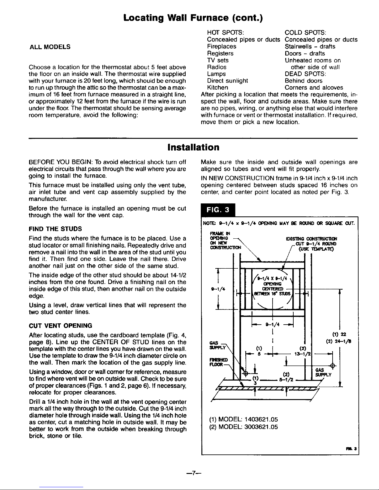
IN NEW CONSTRUCTION frame in 9-1/4 inch x 9-1/4 inch
opening centered between studs spaced 16 inches on
center, and center point located as noted per Fig. 3.
NO'W.: g--1/4 x 9--1,/40P_IING MAY BE ROUND OR SQUARE CUT,
E_lSllNP-CONSlRUC110N
(1) MODEL: 1403621.05
(2) MODEL: 3003621.05
RB.$
--7--
Installation (cont.)
GAS AND ELECTRICAL SUPPLY OPENINGS
Holes must be drilled for the gas line (and electrical
supply if you use an optional Blower Kit). Drill a 1-1/2
inch hole in wall for gas line where indicated on
cardboard template or refer to Fig. 3, page 7. You will
have to determine whether the gas line will enter the
home through the outside wall or wall floor plate. These
instructions can only guide you in where the gas line
will enter the furnace.
IMPORTANT
For walls more than 9 inches thick, read note below.
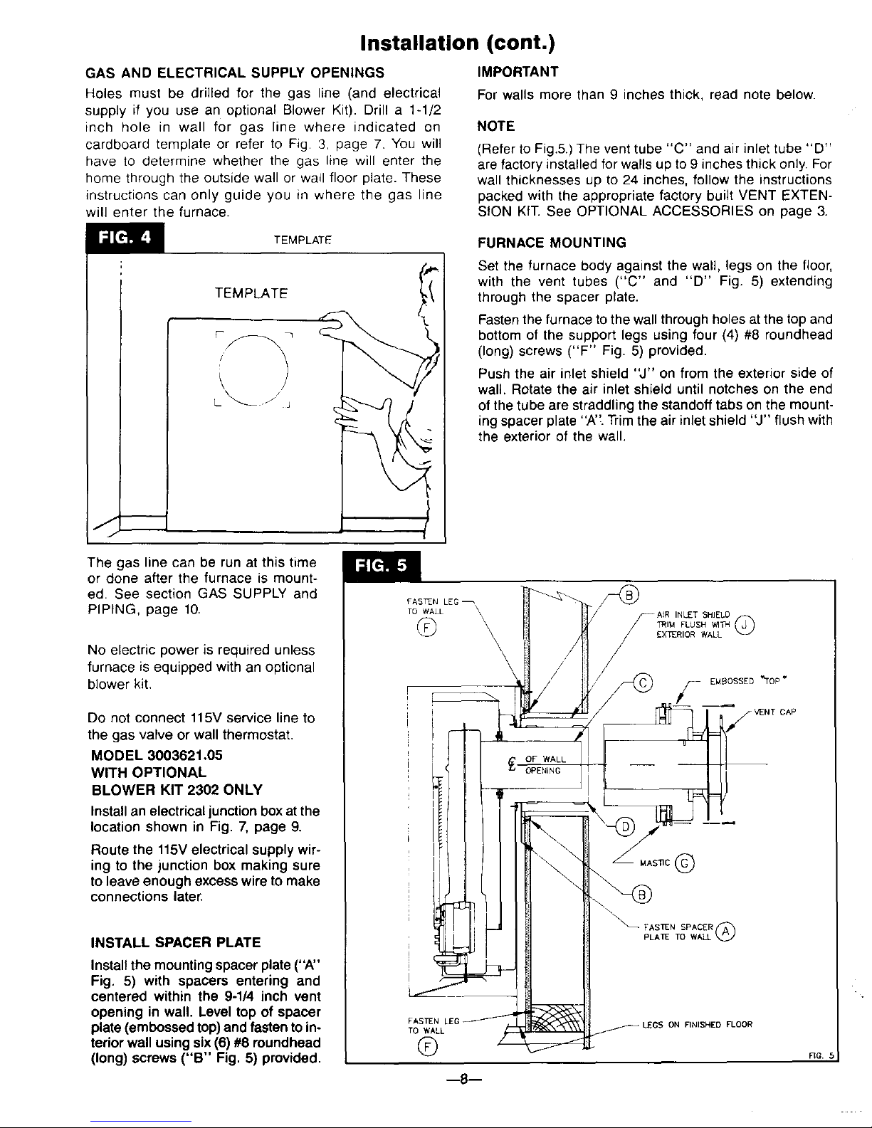
NOTE
(Refer to Fig.5.) The vent tube "C" and air inlet tube "D"
are factory installed for walls up to 9 inches thick only. For
wall thicknesses up to 24 inches, follow the instructions
packed with the appropriate factory built VENT EXTEN-
SION KIT. See OPTIONAL ACCESSORIES on page 3.
TEMPLATE
TEMPLATE
\ /
L_. / j
FURNACE MOUNTING
Set the furnace body against the wall, legs on the floor,
with the vent tubes ("C" and "D" Fig. 5) extending
through the spacer plate.
Fasten the furnace to the wall through holes at the top and
bottom of the support legs using four (4) #8 roundhead
(long) screws ("F" Fig. 5) provided.
Push the air inlet shield "J" on from the exterior side of
wall. Rotate the air inlet shield until notches on the end
of the tube are straddling the standoff tabs on the mount-
ing spacer plate "A'_.Trim the air inlet shield "J" flush with
the exterior of the wall.
The gas line can be run at this time
or done after the furnace is mount-
ed. See section GAS SUPPLY and
PIPING, page 10.
No electric power is required unless
furnace is equipped with an optional
blower kit.
Do not connect 115V service line to
the gas valve or wall thermostat.
MODEL 3003621.05
WITH OPTIONAL
BLOWER KIT 2302 ONLY
Installan electrical junction box atthe
location shown in Fig. 7, page 9.
Route the 115Velectrical supply wir-
ing to the junction box making sure
to leave enough excess wire to make
connections later.
INSTALL SPACER PLATE
Installthe mountingspacer plate ("A"
Fig. 5) with spacers entering and
centered within the 9-1/4 inch vent
opening in wall. Level top of spacer
plate (embossed top) and fasten to in-
terior wall using six (6) #8 roundhead
(long) screws ("B" Fig. 5) provided.
FASTEN LEG
TO WALL \
©
-AIR IN T HI D
/
/
/ L/i_ EMBOSSED _TOP "
CAP
FASTEN
TO WALL
®
ON FINISHED FLOOR
--8--
RG.
Installation (cont.)
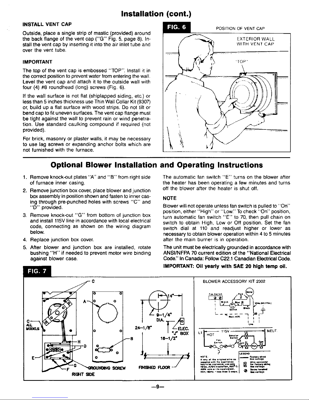
INSTALL VENT CAP
Outside, place a single strip of mastic (provided) around
the back flange of the vent cap ("G" Fig. 5, page 8). In-
stall the vent cap by inserting it into the air inlet tube and
over the vent tube.
IMPORTANT
The top of the vent cap is embossed "TOP". Install it in
the correct position to prevent water from entering the wall.
Level the vent cap and attach it to the outside wall with
four (4) #8 roundhead (long) screws (Fig. 6).
If the wall surface is not flat (shiplapped siding, etc.) or
less than 5 inches thickness use Thin Wall Collar Kit (9307)
or, build up a flat surface with wood strips. Do not tilt or
bend cap to fit uneven surfaces. The vent cap flange must
be tight against the wall to prevent rain or wind penetra-
tion. Use standard caulking compound if required (not
provided).
For brick, masonry or plaster walls, it may be necessary
to use lag screws or expanding anchor bolts which are
not furnished with the furnace.
\
POSITION OF VENT CAP
EXTERIOR WALL
WITH VENT CAP
'TOP"
I
i
Optional Blower Installation and Operating Instructions
1. Remove knock-out plates "A" and "B" from right side
of furnace inner casing.
2. Remove junction box cover, place blower and junction
box assembly in position shown and fasten to inner cas-
ing through pre-punched holes with screws "C" and
"D" provided.
3. Remove knock-out "G" from bottom of junction box
and install 115Vline in accordance with local electrical
code, connecting as shown on the wiring diagram
below.
4. Replace junction box cover.
5. After blower and junction box are installed, rotate
bushing "H" if needed to prevent motor wire binding
against blower case.
The automatic fan switch "E" turns on the blower after
the heater has been operating a few minutes and turns
off the blower after the heater is shut off.
NOTE
Blower will not operate unless fan switch is pulled to "On"
position, either "High" or "Low." Tocheck "On" position,
turn automatic fan switch "E" to 70, then pull chain on
switch to obtain High, Low or Off position. Set the fan
switch dial at 110 and readjust higher or lower as
necessary to obtain blower operation within 4 to 5 minutes
after the main burner is in operation.
The unit must be electrically grounded in accordance with
ANSI/NFPA 70 current edition of the "National Electrical
Code." In Canada: Follow C22.1 Canadian Electrical Code.
IMPORTANT: Oil yearly with SAE 20 high temp oil.
E.-I
=,--,/."Ibs%c.
l 16--1/2"
fiNISHrn FLOORj "
BLOWER ACCESSORY KIT 2302
I illch V_I p,_ )
I
I I I
U_
--9--
 Loading...