

Williams 2519621, 2519622, 3519621, 5019621, 2539622 Owner's Manual
...
50,000
Btu/hr. Model
25,000 and 35,000
Btu/hr. Model
the gas supplier.
WARNING: If the information in these
instructions is not followed exactly, a fire or
explosion may result causing property
damage, personal injury or loss of life.
Owner’s Manual Save this manual for future reference.
Top-Vent Gravity Wall
Furnace
Model Numbers:
2509622; 2539622; 2559622; 3509622; 3539622; 3559622;
5009622; 5039622; 5059622
FOR USE WITH NATURAL GAS ONLY
Model Numbers:
2509621; 2539621; 2559621; 3509621; 3539621; 3559621;
5009621; 5039621; 5059621
FOR USE WITH PROPANE GAS ONLY
READ THIS OWNER’S MANUAL CAREFULLY BEFORE YOU
INSTALL YOUR NEW WILLIAMS WALL FURNACE.
Do not store or use gasoline or other
flammable vapors and liquids in the vicinity
of this or any other appliance.
WHAT TO DO IF YOU SMELL GAS:
Open all windows.
Do not try to light any appliance.
Do not touch any electrical switch; do not
use any phone or cell phone in your
building.
Extinguish any open flame.
Immediately call your gas supplier from
a neighbor’s phone. Follow the gas
supplier’s instructions.
If you cannot reach the gas supplier,
call the fire department.
Installation and service must be performed
by a qualified installer, service agency or
Williams Furnace Co. 250 West Laurel Street Colton, California 92324 U.S.A.
WARNING: Improper installation, adjustment,
alteration, service or maintenance can cause injury
or property damage. Refer to this manual. For
assistance or for additional information consult a
qualified installer, service agency or the gas
supplier.

Warranty & Installation Record – 2
2
Warranty
The manufacturer, Williams Furnace Co., warrants this wall furnace or heater to the original purchaser under the following conditions:
LIMITED ONE-YEAR WARRANTY
1. Any part thereof which proves to be defective in material or workmanship within one year from date of original purchase for use will be replaced at the Manufacturer’s
option, FOB to its factory.
2. No liability is assumed by the Manufacturer for removal or installation labor costs, nor for freight or delivery charges.
LIMITED EXTENDED WARRANTY
1. In addition to the above limited one-year warranty on the complete unit, any combustion chamber which burns out or rusts under normal installation, use and service
conditions during a period of nine years following expiration of the one-year warranty period will be exchanged for a like or functionally similar part.
2. No liability is assumed by the Manufacturer for removal or installation labor costs, nor for freight or delivery charges.
LIMITATIONS
1. THIS LIMITED WARRANTY IS THE ONLY WARRANTY MADE BY THE MANUFACTURER, IMPLIED WARRANTIES OF MERCHANTABILITY OR FITNESS FOR ANY
PARTICULAR PURPOSE ARE LIMITED TO THE SAME ONE YEAR TERM AS THE EXPRESS WARRANTY. UNDER NO CIRCUMSTANCES SHALL THE
MANUFACTURER BE LIABLE FOR INCIDENTAL, CONSEQUENTIAL, SPECIAL OR CONTINGENT DAMAGES OR EXPENSES ARISING DIRECTLY OR INDIRECTLY
FROM ANY DEFECT IN THE PRODUCT OR ANY COMPONENT OR FROM THE USE THEREOF. THE REMEDIES SET FORTH HEREIN ARE THE EXCLUSIVE
REMEDIES AVAILABLE TO THE USER AND ARE IN LIEU OF ALL OTHER REMEDIES.
Some states do not allow limitation on how long an implied warranty lasts, and some states do not allow the exclusion or limitation of incidental or consequential
damages, so the above limitations or exclusions may not apply to you.
2. This warranty does not include any charge for labor or installation.
3. This warranty does not extend to painted surfaces or to damage or defects resulting from accident, alteration, misuses or abuse or improper installation.
4. This warranty does not cover claims which do not involve defective workmanship or materials.
DUTIES OF THE CONSUMER
1. The heating equipment must be installed by a qualified installer and operated in accordance with the installation and homeowner’s instructions furnished with the
equipment.
2. Any travel, diagnostic costs, service labor, and labor to repair the defective unit will be the responsibility of the owner.
3. A bill of sale, cancelled check, payment record or permit should be kept to verify purchase date to establish the warranty period.
4. Have the installer enter the requested information in the space below.
GENERAL
1. The manufacturer neither assumes nor authorizes any person to assume for it any other obligation or liability in connection with said equipment.
2. Service under this warranty should be obtained by contacting your dealer. Provide the dealer with the model number, serial number, and purchase date verification.
3. If, within a reasonable time after contacting your dealer, satisfactory service has not been received, contact: Customer Service Department, 250 West Laurel Street,
Colton, CA 92324 for assistance.
4. THIS WARRANTY GIVES YOU SPECIFIC LEGAL RIGHTS AND YOU MAY ALSO HAVE OTHER RIGHTS WHICH VARY FROM STATE TO STATE.
Installation Record
Model No. ______________________________________________________________ Serial No. ___________________________
Original Purchaser ____________________________________________________________________________________________
Address ____________________________________________________________________________________________________
City and State ___________________________________________________________ Zip ________________________________
Dealer _____________________________________________________________________________________________________
Address ____________________________________________________________________________________________________
City and State ___________________________________________________________ Zip ________________________________
Installation Date _______________ Name ________________________________ Signature_________________________________
(Dealer or authorized representative who certifies that this appliance is installed in accordance with Manufacturer’s instructions and local codes.)

Contents
Your Williams Warranty ................................................................. 2
Installation Record ......................................................................... 2
Table of Contents .......................................................................... 3
Safety Rules .................................................................................. 4
Introduction .................................................................................... 5
Basic Materials Needed................................................................. 5
Basic Tools Needed ...................................................................... 5
Optional Accessories ..................................................................... 5
Installing Your Wall Furnace .......................................................... 6
Locating Wall Furnace and Thermostat ..................................... 6-7
Combustion & Ventilation Air ..................................................... 7-9
Installation
Recessed Mount Installation ........................................ 10-11
Surface Mount Installation ........................................... 12-13
Vent Installation ................................................................. 14
Attaching Your Furnace ......................................................... 15-16
Gas Supply and Piping .......................................................... 16-18
Front Panel Installation ................................................................ 18
Thermostat Installation ................................................................ 19
Start Up Procedure ................................................................ 20-21
Stay Safe………………………………………………………….22-23
Operating Your Furnace………………………………………...22-23
How to Care for Your Furnace ……………………….………..24-25
Installing Your Blower Accessory………………………………25-26
Blower Accessory Replacement Parts....….…………………..27-28
Installing Your Motorized Rear Outlet Accessory...….............29-30
Motorized Rear Outlet Replacement Parts...……………....…31-32
Furnace Replacement Parts …………………………..……….32-37
Troubleshooting Chart...…..…………………………………….38-39
Service Hints………………………………………………...............40
Quick Reference: Here’s how to…
Installing Your Furnace ............................................................ 6-20
Recessed Mount, Surface Mount, and Vent Installation are
explained starting on page 6.
Operating Your Furnace ........................................................ 22-23
Igniting your furnace for the first time.
Caring for Your Furnace ........................................................ 24-25
Learn how to keep your new Williams Furnace operating.

4
WARNING: Do not install any of these furnaces (Natural or
L.P. Gas) in mobile homes, trailers or recreational vehicles.
Safety Rules
WARNING: Read these rules and the instructions
carefully. Failure to follow these rules and
instructions could cause a malfunction of the
furnace. This could result in death, serious bodily
injury and/or property damage.
INSTALLATION MUST CONFORM TO LOCAL CODES. IN THE
ABSENCE OF LOCAL CODES, INSTALLATION MUST
CONFORM TO THE NATIONAL FUEL GAS CODE, ANSI Z223.1.
THE APPLIANCE, WHEN INSTALLED MUST BE
ELECTRICALLY CONNECTED AND GROUNDED IN
ACCORDANCE WITH LOCAL CODES OR, IN THE ABSENCE
OF LOCAL CODES, WITH THE CURRENT NATIONAL
ELECTRICAL CODE ANSI/NFPA NO. 70.
8. Vent the furnace directly to the outdoors, so that harmful
gases will not collect inside the building. Follow the venting
instructions for your type installation exactly. Use only the
type and size of vent pipe and fittings specified.
9. Provide for adequate combustion and ventilation air. See
page 7. The flow of this air to the furnace must not be
blocked.
10. NEVER vent flue gases into another room, a fireplace or
any space inside a building. This could cause property
damage, bodily injury or death.
11. NEVER test for gas leaks with an open flame. Use a soap
solution to check all gas connections. This will avoid the
possibility of fire or explosions.
IN CANADA: Installation must conform to local
codes or, in the absence of local codes, the current
CAN/CGA B149 Installation code.
The appliance, when installed, must be grounded in
accordance with local codes, with the current CSA
C22.1 Canadian Electrical Code.
Reference is made in this manual regarding gas
type as L.P.G. Be advised that L.P.G. is not
available in Canada; refer to Propane/L.P. Gas.
WARNING: Do not use this furnace if any part has
been under water. Immediately call a qualified
service technician to inspect the furnace and to
replace any part of the control system and any gas
control which has been under water.
1. Use only manufacturer’s replacement parts. Use of any
other parts could cause injury or death.
2. DO NOT install the furnace where it could be isolated by
closing doors to the heated space.
3. DO NOT install these furnaces in a travel trailer, recreational
vehicle or mobile home.
4. MAINTAIN all clearances specified in section “Locating Wall
Furnace and Thermostat” and “Vent Installation.”
5. BE SURE the furnace is for type of gas being used. Check
the nameplate by the gas valve in the lower cabinet. Do not
change it to use other gases without the proper
manufacturer’s gas conversion kit.
6. For natural gas, the minimum inlet gas supply pressure for
the purpose of input adjustment is 5” water column. The
maximum inlet gas supply pressure is 7” water column. For
L.P. gas, the minimum inlet gas supply pressure for the
purpose of input adjustment is 11” water column. The
maximum inlet gas supply pressure is 13” water column.
7. Any safety screen, guard or parts removed for servicing this
appliance must be replaced prior to operating the appliance
to avoid property damage, bodily injury or death.
12. , ALLOW furnace to cool before servicing. Always shut off
electricity and gas to furnace when working on it. This will
prevent any electrical shocks or burns.
13. DUE TO HIGH TEMPERATURES, locate the furnace out of
traffic and away from furniture and draperies.
14. ALERT children and adults to the hazards of high surface
temperatures and warn them to keep away to avoid burns
or clothing ignition.
15. CAREFULLY supervise young children when they are in the
same room with the furnace.
16. DO NOT place clothing or other flammable material on or
near furnace.
17. INSTALLATION and REPAIR must be done by a qualified
service person. The appliance should be inspected before
use and at least annually by a professional service person.
More frequent cleaning may be required due to excessive
lint from carpeting, bedding material, etc. It is imperative
that control compartments, burners and circulating air
passages be kept clean.
18. BEFORE INSTALLING: To avoid electrical shock, turn off
electrical circuits that pass through the wall where you are
going to install the furnace.
19. BE AWARE of good safety practices by wearing personal
protective equipment such as gloves and safety glasses to
avoid being injured by sharp metal edges in or around the
furnace while cutting or drilling holes in wood and/or sheet
metal.
20. CAUTION: Label all wires prior to disconnection when
servicing controls.
21. DO NOT store or use gasoline or other flammable liquids or
vapors near the furnace.

Introduction – 5
Introduction
The following steps are all needed for proper installation and safe operation of your furnace. If you have any doubts as to any
requirements, check with local authorities. Obtain professional help where needed. All of the checks and adjustments in the Start-Up
Procedures are vital to the proper and safe operation of the furnace. Please read the instructions before you install and use your
furnace. This will help you obtain the full value from this furnace. It could also help you avoid needless service costs if the answer to
the problem is found within this instruction manual.
Always consult your local heating or plumbing inspector, building department or gas utility company regarding regulations codes or
ordinances which apply to the installation of a vented wall furnace.
Check the furnace nameplate, located in the burner compartment, to make sure your furnace is equipped to operate on the type of gas
available (either natural or L.P. gas). DO NOT convert the furnace from natural gas to L.P. gas or from L.P. gas to natural gas without
the proper manufacturer’s gas conversion kit.
Combustion air is drawn in from the room where the furnace is located and is vented out of the top of the furnace vertically through vent
piping in the stud space to a roof vent top. Vent material is not supplied with the furnace.
This furnace is equipped with a vent safety shutoff system designed to protect against improper venting of combustion products.
Operation of this wall furnace when not connected to a properly installed and maintained venting system or tampering with the vent
safety shutoff system can result in carbon monoxide (CO) poisoning and possible death.
The efficiency rating of this furnace is a product thermal efficiency rating determined under continuous operating conditions and was
determined independent of any installed system.
Basic Materials Needed
Pipe and fittings to make gas connections to the furnace.
Vertical venting materials. See page 14, Figure 8.
Basic Tools Needed
Hand drill or properly grounded electric drill
Expansion bit 1/2” to 1-5/8” or 1/2” and 1-1/2” blade bits
1/8” and 3/16” drill bit (metal)
6 ft. folding rule or tape measure
Screwdriver (medium blade)
Screwdriver (Phillips head)
Pliers (wire cutting)
Helpful Installation Information
The following booklets will help you in making the installation:
ANSI/NFPA 70, or current edition “National Electrical Code”. In Canada: CSA C22.1 Canadian Electrical Code.
American National Standard Z223.1 or current edition of the “National Fuel Gas Code.”
Obtain from the American National Standard Institute, Inc., 1430 Broadway, New York, NY 10018. In Canada, CAN/CGA B149.
Optional Accessories
Blower Accessories 2901, 2907 - May be used on all models and mounts on top of a furnace. This blower increases circulation of
warm air through the heated space. A 115V outlet adjacent to the furnace is required.
Trim Strip Kit 4701 - Provides a finished edge for sides of the wall furnace.
Free Standing Accessory 4901 - May be used with single-sided models. This accessory allows the furnace to be mounted on the
surface of a wall.
Vent Adapter Kit 9902, 9910 - Optional vent adapter, typically used when the furnace is vented into a properly lined chimney.
Rear Outlet Registers 6901, 6919, 6920 - May be used with single-sided models when recessed into a standard 2x4 inch interior stud
partition. This accessory directs some of the heated air into the room opposite the one in which the furnace is installed.
Oval B/W Vent Kit 9901 - This U.L. listed B/W vent kit contains four feet of oval, double-walled vent pipe, plate spacers and base or
hold-down plate that starts the venting from the top of furnace. See Vent Installation on page 14 for additional items you will need.
Plaster Ground Kit 6905 - Used for 6901 or 6919 Rear Outlet Registers.
Gas Conversion Kits - See page 16.
Pipe Joint Compound resistant to L.P. Gases.
Electrical wiring supplies as needed. Minimum wire size is #14
gauge copper.
Hammer
Stud Locator or small finishing nails
Tin Snips
8” adjustable wrench
12” adjustable wrench
Two, 10” or 12” pipe wrenches
Gloves and safety glasses
6
Installing Your Furnace
The following steps are needed for proper installation and safe
operation of your furnace. If you have any doubts as to any
requirements, obtain professional help. Remember to ALWAYS
consult your local heating or plumbing inspector, building
department or gas utility company regarding regulations, codes,
or ordinances which apply to the installation and location of a
vented wall furnace.
IMPORTANT
2. Install the furnace in accordance with local codes or
ordinances and instructions provided. In the absence of
local codes or ordinances, install the furnace to conform
with the current edition of the National Fuel Gas Code,
NFPA 54, ANSI Z223.1/Canadian Installation Code,
CAN/CGA B149.
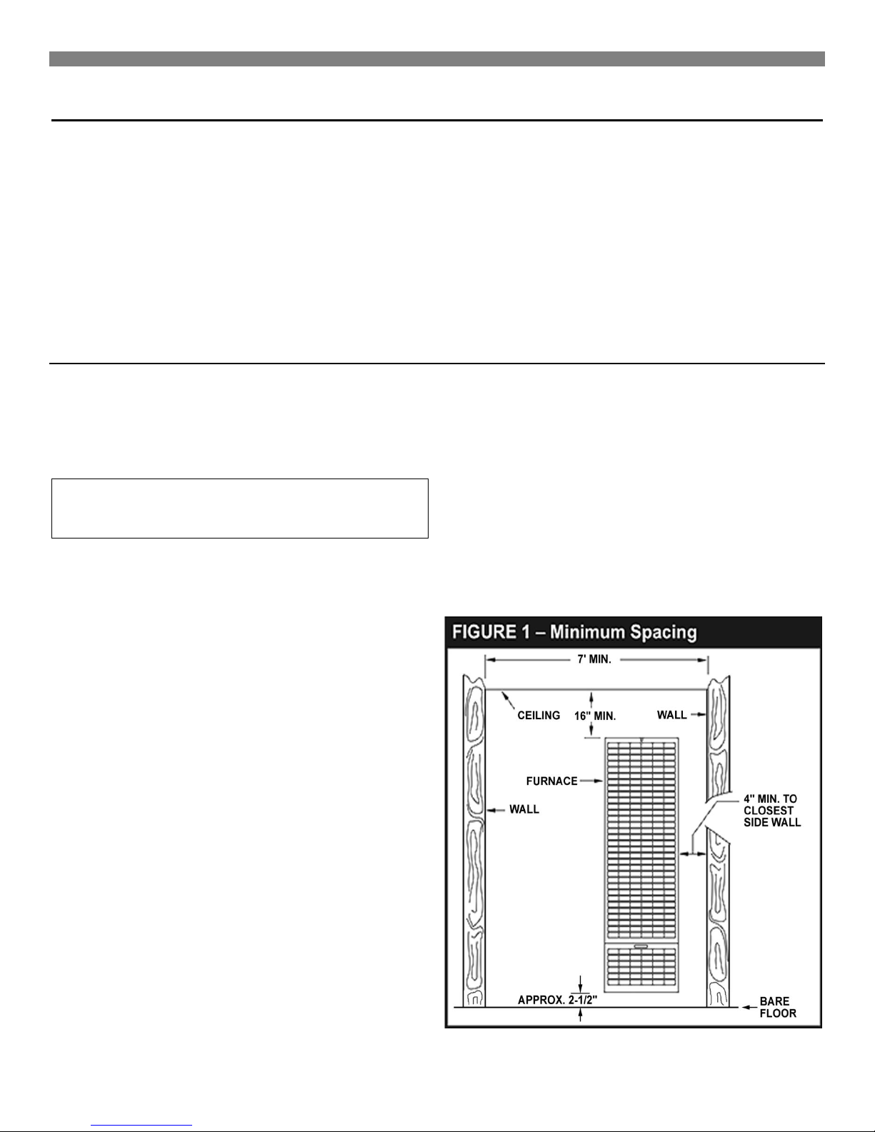
3. Maintain minimum clearances: Floor 2½-inches, ceiling 16inches, side wall 4-inches.
For satisfactory and trouble-free operation, be sure to:
1. Locate the furnace properly within the space to be heated.
Locating Wall Furnace & Thermostat
The furnace is installed between 2x4 inch wall studs spaced on
16-inch centers or a stud space that can be framed in to 16-
inches.
Consider the following points before attempting to install the
furnace:
CAUTION: Do not make cutouts in the wall or
ceiling before checking in the attic for ceiling joist
locations and proposed venting.
1. Locate the furnace near the center of the space to be
heated for good air circulation. Do not put it behind a door
or draperies. Do not install the furnace where it could be
isolated by closing doors to the heated space. Do not
locate the furnace where a door could swing over the front
panel or where circulation could be retarded by furniture or
cabinets.
2. Check the minimum spacing needs as shown in Figure 1.
3. The top of the furnace must be at least 16-inches from the
ceiling.
4. When the furnace is properly installed with legs resting on
the floor plate, it sets the dimension from the face panel to
the bare floor. (Approximately 2½-inches depending on the
thickness of floor plate).
5. A protective barrier (metal or wood), cut to match the width
and depth of the furnace, should be used to cover over
any floor coverings such as carpet or vinyl under the
furnace. At no time should the dimension from the bottom
of the face panel to the protective barrier be less than 1½inches.
6. In the space to be heated, the side of the furnace may be
as close as 4-inches to an intersecting wall. The recessed
portion may have 0-inches clearance to combustible
material.
7. Select a location that will provide adequate accessibility
clearance for servicing and proper operation.
4. Provide enough combustion and ventilation air.
8. After picking a location, inspect the wall, floor, attic and
roof areas. Make sure there are no pipes, wiring, bracing,
etc., that will interfere with furnace or vent installation. If
required, move them or pick a new installation location.
9. Be sure that gas piping and electrical wiring can be
brought to the location. Electrical wiring is required for
optional blower accessory.
10. If installing the thermostat on the wall, locate the
thermostat approximately 5-feet above the floor on an
inside wall where it will sense the average room
temperature.

Locating Wall Furnace & Thermostat (continued)
WARNING: Danger of property damage, bodily injury or loss of life. Even when a house meets
requirements for unconfined space with adequate air infiltration, it is recommended that a fresh air intake be
installed to lessen the possible dangers from any future changes on the home
Installing Your Furnace
Locating Wall Furnace & Thermostat (continued)
The thermostat should be sensing average room temperature;
avoid the following:
HOT SPOTS: COLD SPOTS:
Concealed pipes or ducts Concealed pipes or ducts
Fireplaces Stairwells – drafts
Registers Doors – drafts
TV sets Unheated rooms on
Radios other side of wall
Lamps
Direct sunlight DEAD SPOTS
Kitchen Behind doors
Corners and alcoves
Combustion & Ventilation Air
WARNING: Danger of property damage, bodily
injury or loss of life. The furnace and any other fuelburning appliances must be provided with enough
fresh air for proper combustion and ventilation of
flue gases. Most homes will require that outside air
be supplied into the heated area.
The high cost of energy for home heating has brought about new
materials and methods used to construct or remodel most current
homes. The improved construction and additional insulation has
reduced the heat loss and made these homes much tighter
around windows and doors so that infiltrated air is minimal. This
creates a problem to supply combustion and ventilation air for
gas-fired or other fuel burning appliances. Any use of appliances
that pull air out of the house (clothes dryers, exhaust fans,
fireplaces, etc.) increases this problem and appliances could be
starving for air.
The combination of a tight energy efficient home with the use of
exhaust fans, fireplaces, clothes dryers, and gas appliances result
in more and more air being drawn from the house until fresh air
may be sucked back into the house down a furnace flue or
fireplace chimney. Carbon monoxide can be the result. Carbon
monoxide (CO) is a colorless, odorless gas produced when fuel is
not burned completely or when the flame does not receive
sufficient oxygen. Automobiles, charcoal, wood fires and
improperly vented or air-starved coal, oil and gas furnaces or
other appliances can produce carbon monoxide.
Do not install furnace in the same room or near a wood solid fuel
burning fireplace.
After picking a location that meets the requirements, check the
walls, attic and roof to make sure there are no obstructions such
as pipes, electrical wiring, etc., which could interfere with the
installation of the furnace or vent pipe. If required, move them or
pick a new location.
WARNING: Danger of property damage, bodily
injury or loss of life. Do not install the furnace in any
area where oxygen is in use.
BE AWARE OF THESE AIR-STARVATION SIGNALS:
1. Headaches, nausea, dizziness.
2. Excessive humidity shown by heavily frosted windows or a
moist "clammy" sensation.
3. Fireplace smoke fills the room or will not draw.
4. Furnace flue backs up.
AIR REQUIREMENTS
The requirements for providing air for combustion and ventilation
are listed in the National Fuel Gas Code NFPA 54/ANSI Z223.1 (in
Canada: CAN/CGA B149). Most homes will require that outside
air be supplied to the heated area by means of ventilation grilles
or ducts connecting directly to the outside or spaces open to the
outdoors such as attic or crawl space. The only exception is when
the heated area meets the requirements and definitions for an
unconfined space with adequate air infiltration.
All air openings and connecting ducts must comply with the
following:
If the furnace is installed in an area with another gas appliance(s),
the total input rating of all appliances must be considered when
determining the free area requirements for combustion and
ventilation air openings.
Ducts must have the same cross-sectional area as the free area
of the openings to which they connect. The minimum dimension
of rectangular air ducts must not be less than 3-inches in length or
height.
8
Hole Placement - Example
Square inches
of Opening
Installing Your Furnace
Combustion & Ventilation Air (continued)
LOUVERS / GRILLES AND SCREENS COVERING
FREE AREA OPENINGS
If a screen is used to cover the opening(s), it must not be smaller
than 1/4-inch mesh. Use the free area of a louver or grille to
determine the size opening required to provide the free area
specified. If the free area is not known, assume a 20% free area
for wood and a 60% free area for metal louvers or grilles.
INFILTRATION AIR
If your furnace is in an open area (unconfined space), the air that
leaks through the cracks around doors and windows may be
enough for combustion and ventilation air. The doors should not
fit tightly. The cracks around windows should not be caulked or
weather stripped.
Spillage means air starvation. A fresh air duct or air intake
opening must be installed to provide air directly to the furnace or
other gas appliances.
If spillage exists or when the furnace is in a building of tight
construction where the windows and doors are weather stripped,
air for combustion and ventilation must be obtained from outdoors
or space open to the outdoors.
B. Draft Hood Spills
If there is spillage at a draft hood (match goes out or flame wavers
away from draft hood), check for plugged flue connectors and
chimneys. Repair blockage and test again.
If you have a fireplace, open a window or door near the fireplace
and then check for spillage. If spillage stops, do not use the
fireplace without a nearby window or door open until you can
supply fresh air by a permanent duct.
If you have kitchen and bathroom exhaust fans, turn them off and
check for spillage. If spillage stops, do not use exhaust fans
(circuit breakers for fans should be turned off) until you can supply
fresh air by a permanent duct.
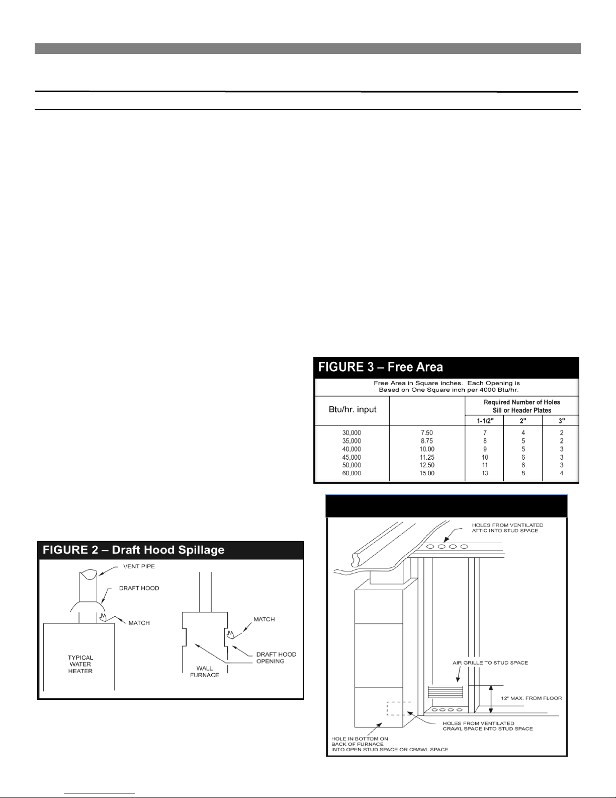
Provide opening(s) having a total free area of one-square-inch per
4,000 Btu/hr. of the total combined input ratings for all appliances
in the area. The required free area is shown in Figure 3. This
fresh air opening or duct must terminate at a point not more than
one-foot above the floor. It must have at least one-square inch of
free area for each 4,000 Btu/hr. of input of all appliances in area.
To determine if infiltration air is adequate, perform the following
checks:
1. Close all doors and windows. If you have a fireplace, start a
fire and wait until flames are burning vigorously.
2. Turn on all exhausting devices, i.e., kitchen and bathroom
exhaust fans; water heaters (gas and electric).
3. Turn on all vented gas appliances, i.e., heating equipment
(includes any room heaters), water heaters.
4. Wait ten (10) minutes for drafts to settle.
5. Check for draft hood spillage at each appliance. Hold a lit
match two-inches from the draft opening. (Figure 2).
A. No Spillage
If the match flame pulls toward draft hood, this indicates sufficient
infiltration air. Return exhausting devices and appliances to the
condition you found them.
Examples of Grille Placement
Examples of Air Inlets and Outlets
Max.
Installing Your Furnace
Combustion & Ventilation Air (continued)
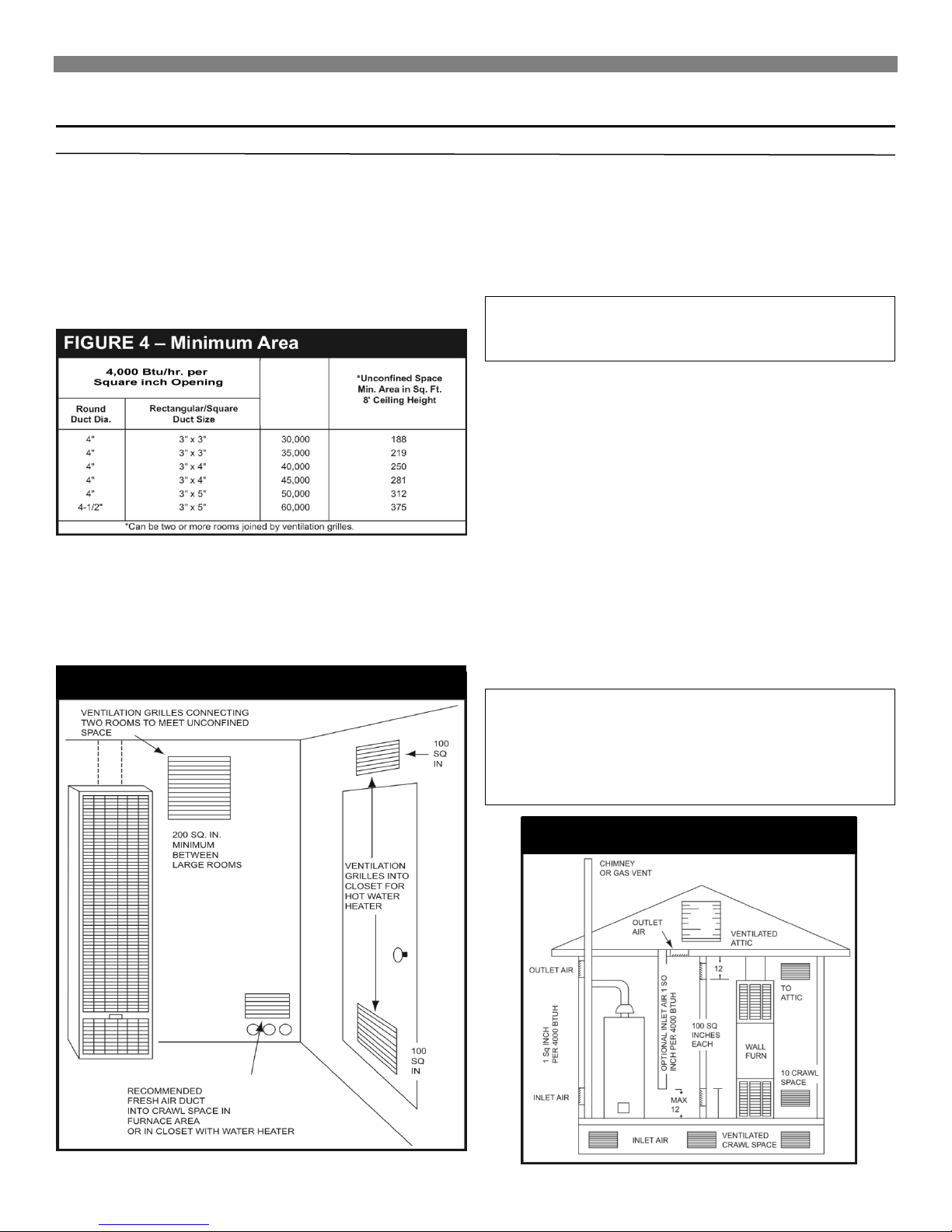
FURNACE LOCATED IN UNCONFINED SPACE
An unconfined space must have a volume of a minimum 50 cubic
feet per 1,000 Btu/hr. of the total combined input of all appliances
in the area. Adjoining rooms may be included only if there are no
doors between the rooms or if special provisions are made such
as ventilation grilles installed between connecting rooms. Figure
4 outlines the minimum area in square feet, based on 8-foot
ceiling heights for various Btu/hr. input ratings.
Btu/hr.
Input
FURNACE LOCATED IN CONFINED SPACE
If a furnace is installed in a confined space, it must be provided
with free air for proper combustion and ventilation of flue gases by
one of the following methods:
A. Air From Inside the Building
If the confined space adjoins an unconfined space, provide two
permanent openings. One within 12-inches of the top and another
within 12-inches of the bottom of the room directly connected to
the unconfined space. Each opening must have a free area of at
least 100-square inches or 1-square inch per 1,000 Btu/hr. of
input for all appliances combined.
WARNING: Danger of property damage, bodily
injury or death. The adjoining unconfined space
must have adequate air infiltration.
B. Air From Outdoors
If confined space does not adjoin an unconfined space, then air
must be provided from outdoors or spaces open to the outdoors
such as an attic or crawl spaces.
Openings for inlet or outlet air should NOT be made into an attic
area if the attic is equipped with a thermostat controlled power
vent.
Provide two permanent openings, one within 12-inches of the top
and bottom of the room connecting directly to, or by using ducts,
with the outdoors or areas open to fresh air.
If the opening connects directly to, or with vertical ducts, the free
area of each opening must be at least 1-square inch per 4,000
Btu/hr. of the combined input of all appliances in the area.
If horizontal ducts are used, the free area of each opening must
be at least 1-square inch per 2,000 Btu/hr. of the combined input
of all appliances in the area.
WARNING: Danger of illness, bodily injury or
death. Draft hood spillage, with unobstructed vents,
indicates that additional air must be brought into the
structure from the outside. Keep a window open
(minimum 2-inches) near the appliance until a
permanent air duct is installed.
10
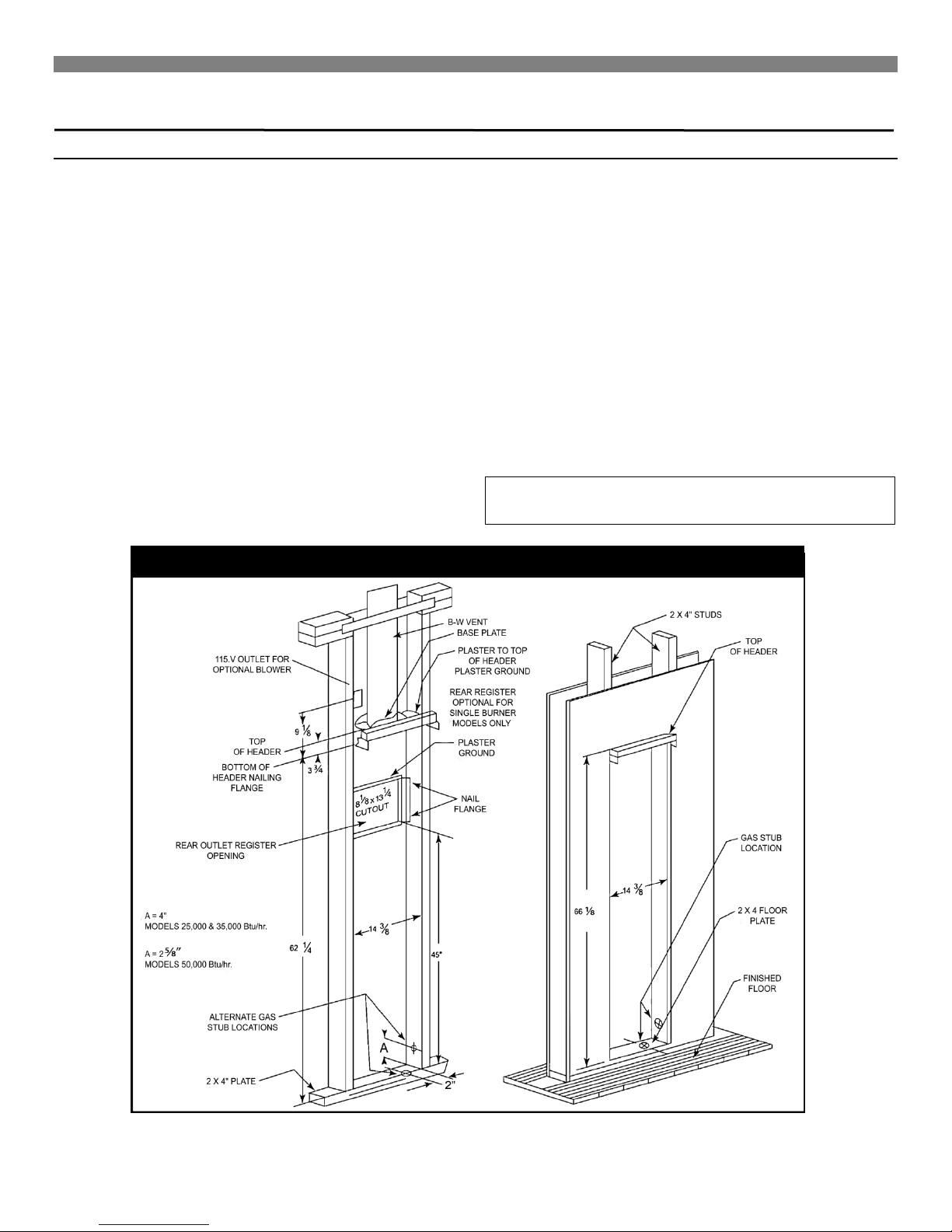
FIGURE 5 – Recessed Wall Mount Installation
Installing Your Furnace
Recessed Wall Mount Installation
On models 2509621, 2539621, 2559621, 2509622, 2539622,
2559622, 3509621, 3539621, 3559621, 3509622, 3539622, and
3559622, the maximum recess depth from rear of furnace forward
is 4½ inches.
FIND THE STUDS AND CEILING JOINTS
Use a stud locator or small finishing nails. Repeatedly drive and
remove a nail into the wall in the area of the stud until it is located.
Then find the inside edge of the stud. Leave the nail at this
location.
The other stud should be about 14½-inches from the one found.
Drive finishing nails on the inside of this stud. Draw wall cutout to
required size as shown in Figure 5. If wall studs are not on
16-inch centers. See "CLOSE OFF STUD SPACE.” (Figure 6).
CUT WALL OPENING
Cut wall opening 14⅜-inches wide and 66⅛-inches high
measured from the top of the floor plate. (Figure 5). All corners
must be square.
INSTALLATION OF REAR OUTLET REGISTER
The optional rear outlet register may be installed when the
furnace is recessed into the wall. In new construction, install the
rear outlet plaster ground at the same time you install the header
plate. For existing construction, make the necessary cutout and
install the plaster ground before you install the furnace. See
instructions packed with accessory and Figure 5.
Do not allow wall finish material to project into the furnace recess.
Do not install rear outlet register where grille may be blocked by a
door, curtains or any other obstruction.
GAS SUPPLY OPENING
A hole must be drilled for the gas line. Decide whether the gas
line will come through the floor or wall. Drill a 1½-inch hole
through the floor or wall as needed. (Figure 5).
CAUTION: Be careful not to damage any furnace
components while making any alternate hole.
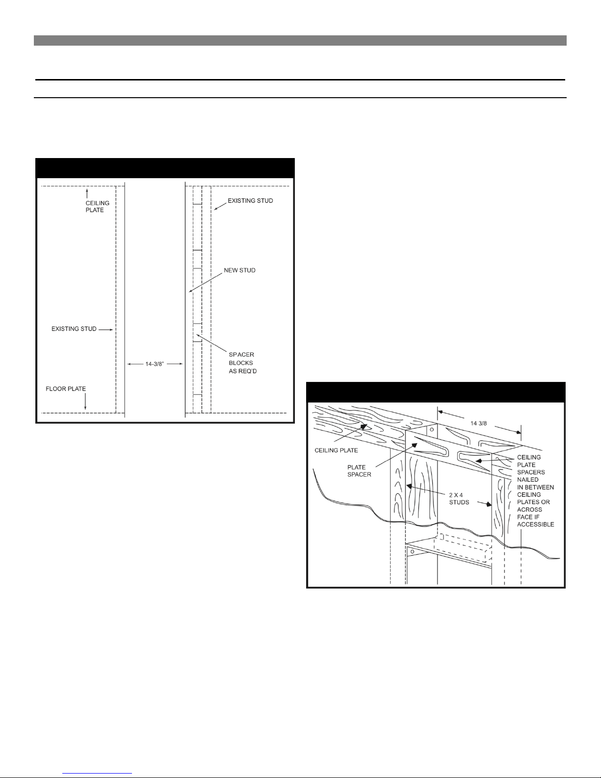
FIGURE 6 – Close Off Stud Space
FIGURE 7 – Ceiling Plate Opening
Installing Your Furnace
Recessed Wall Mount Installation (continued)
CLOSE OFF STUD SPACE (If Required)
If studs are not on 16-inch centers, cut the hole for the furnace
next to an existing stud and frame in the other side using a 2x4
and spacer blocks as required. (Figure 6).
I
INSTALL VENT BASE PLATE (HOLD-DOWN PLATE)
Position base plate on top of header plate and fasten with screws.
Note: Hold down plate is not included.
HEADER PLATE (VENT SUPPORT)
Measure upward 62¼-inches from the top of the floor plate. Place
a mark on each stud at this distance. (Figure 5). Place the
header plate between the studs with the lower edges even with
marks on the studs. Make sure header plate is level.
Locate rear edge of nailing tabs at back of the header. Nail
header plate to the 2x4 studs which will center the vent collar in
the wall. (Figure 5).
INSTALL CEILING PLATE SPACER
Nail the ceiling plate spacers either across or in between the cut
out section of ceiling plate. If nailed between, ends must be bent
at 90 degrees. They must be fastened along each long edge of
the ceiling plate hole to hold the oval vent pipe in the center of the
hole. Ceiling plate spacers preserve structural strength and
position oval vent pipe in the center of the cut out opening.
Ceiling plate spacers are not included. (Figure 7).
CEILING PLATE OPENING
Cut away the ceiling plate between the studs where the furnace is
to be installed. Work from the top in the attic. If there is no
access to the top, remove the wall covering between the two wall
studs all the way to the ceiling. Work through this opening. Cut
out the entire plate so the plate edges will be even with the inner
face of the 2x4 studs. (Figure 7).
12
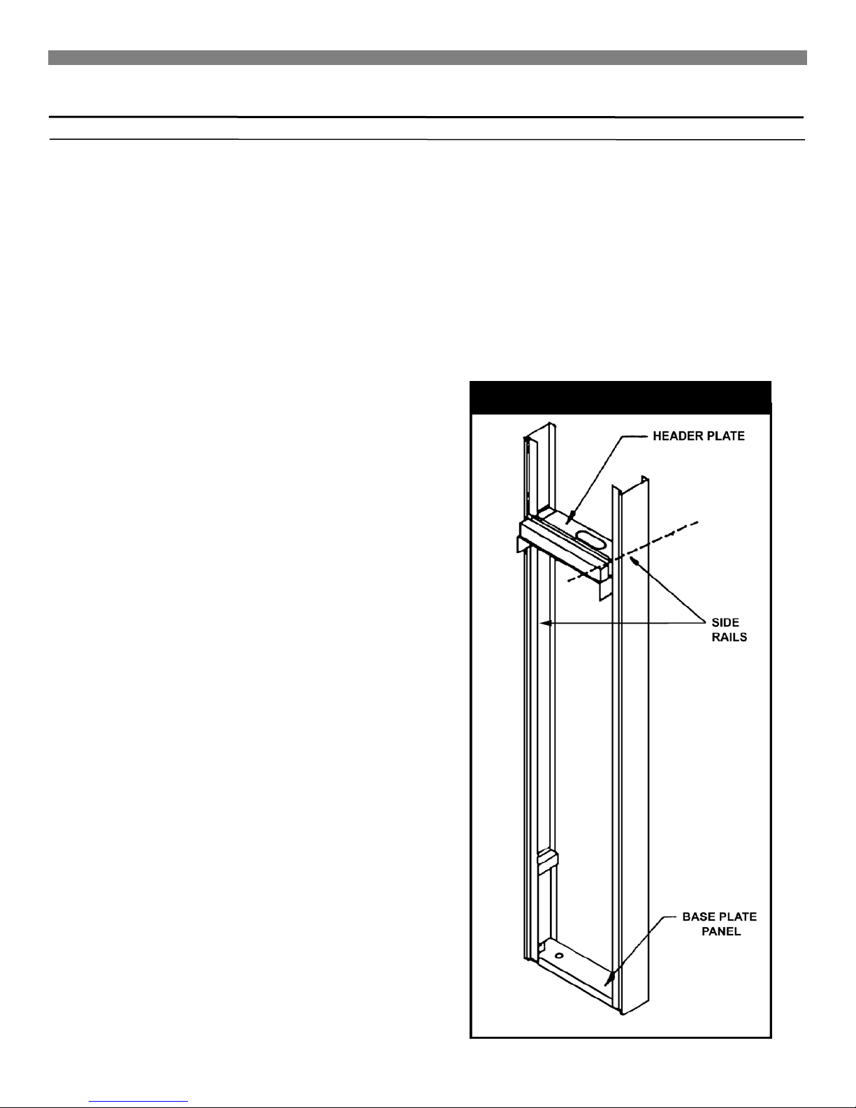
FIGURE A
Installing Your Furnace
Surface Mount Installation
The use of the optional Free Standing Accessory No. 4901 allows
single-sided furnaces to be surface mounted instead of recessed
into a wall. This is ideal for remodeling existing masonry wall
construction or when studding is substandard. This kit drastically
cuts installation time and eliminates the expense of cutting into
the walls and ceiling plates. Be sure this accessory is of the type
and design required for the use with your furnace.
NOTE: After picking a location that meets the requirements,
check the wall, attic, and roof to make sure there are no
obstructions such as pipes, electrical wiring, etc., which could
interfere with the installation of the furnace or vent pipe. If
required, move them or pick a new location.
FIND THE WALL STUDS OR CEILING JOISTS
Find two studs or joists at the spot where the furnace is to be
located. Use a stud locator or small finishing nails. Repeatedly
drive and remove a nail into the wall or ceiling in the area of the
stud or joust until you find it. Then find the its side and leave the
nail there. Drive another nail just on the other side other the same
stud or joist.
The inside of the next stud or joist should be about 14½ inches
from the first one found. Drive a nail on the inside of this stud or
joist.
Using the nails as a guide, draw two lines down the side of the
wall from the ceiling to locate the furnace and ceiling hole cutout
for venting.
FREE STANDING ACCESSORY ASSEMBLY & INSTALLATION
Utilizing the holes provided in the furnace legs, secure the
furnace to the brackets attached to the bottom panel with two
(2) #10, ¾” screws.
9. Install the vent enclosure panel, fastening it to the side rails
with six (6) #6, ⅜” screws. Trim the bottom of the panel to fit
the header plate.
10. Install gas inlet through the back wall or one of the two holes
provided in the bottom base plate panel. (Figure D.) Connect
gas line to furnace. See Gas supply and Piping, page 17.
11. Install furnace face panel. See Front Panel Installation,
page 18. NOTE: The panel recesses ¼-inch between the
vertical edges of the enclosure.
1. Attach the base plate panel as shown in Figure A to the
bottom of the side rails with four (4) # 6, ⅜” screws.
2. Attach the header plate, (included with the furnace), to the
side rails using four (4) #8, ⅜” screws. Flanges of the header
plate go against the wall. (Figure A).
3. Install extension side rails as shown in Figure A, by
telescoping them inside the lower side rails. Adjust the
extension side rails by sliding them up or down to ceiling
height. Maximum: 8 feet 9 inches, Minimum: 7 feet 9 inches.
4. If the wall has a baseboard, cut the baseboard out to fit
against the side rails. Stand the side rails against the wall and
fasten them to the wall securely with screws or bolts in the
holes provided. Use a level to assure the enclosure is plumb.
Screws and bolts for wall fastening are not included.
5. After positioning the enclosure, cut a 3½ X 14 inch hole in the
ceiling, centered between the studs or joists as shown in
Figure B.
6. Cut ¼ inch off each end of the ceiling spacer plate. Place the
ceiling spacer plate to the back of the wall and centered in the
enclosure as shown in Figure C.
7. Install Type B/W vent though the roof and studs or joists in
accordance with the installation instructions packed with the
furnace and local codes. See Vent Installation, page 14.
8. Set the furnace body into position. (Figure 9), page 15. The
furnace legs will rest on the bottom of the base plate panel.
 Loading...