

Williams 2001612, 3501522, 2001622, 3501512, 3501912 Owner's Manual
...
MODEL NOS:
FOR NAT. GAS ONLY
2001612; 2001622
3501512; 3501522
3501912; 3501922
5001512; 5001522
5001912; 5001922
6501512; 6501522
6501912; 6501922
MODEL NOS.
FOR L.R GAS ONLY
2001611 2001621
3501511 3501521
3501911 3501921
5001511; 5001521
5001911; 5001921
6501511; 6501521
6501911; 6501921
INSTALLATION & OPERATING INSTRUCTION MANUAL
350 MODEL SERIES SHOWN
READ THIS OWNERS MANUAL
CAREFULLY BEFORE YOU INSTALL
YOUR NEW WILLIAMS
VENTED ROOM HEATER
WARNING: Improper installation, adjust-
ment, alteration, service or maintenance
can cause injury or property damage.
Refer to this manual. For assistance or
additional information consult a qualified
Installer, service agency or the gas
supplier.
WARNING: Do not install any of these fur-
naces (Natural or L.P. Gas) in mobile
homes, trailers, or recreational vehicles.
WARNING: If the information in this l
manual isnotfollowedexactly, a fireor ex-
I
plosion may result causing property
damage, personal injury or loss of life.
-- Do notstoreor use gasolineorother flam-
mable vapors and liquids in the vicinity
of this or any other appliance.
-- WHAT TO DO IF YOU SMELL GAS
• Open all windows.
• Do not try to light any appliance.
• Do not touch any electrical switch; do
not use any phone in your building.
• Extinguish any open flame.
• Immediatelycallyourgas supplierfrom
a neighbor's phone. Follow the gas
supplier's instruction.
• Ifyou cannot reach your gas supplier,
call the fire department.
-- Installation and service must be per-
formed by a qualified installer, service
agency or the gas supplier.
WILLIAMS Furnace Co., 225 Acacia St., Colton, CA 92324
PRINTED IN USA 4/98 P500407

IMPORTANT
TO THE PURCHASER: Keep this warranty and the installation and homeowner's instructions for your future reference.
LIMITED WARRANTY
The Manufacturer, Williams Furnace Co., warrants this wall furnace or heater to the original purcheser under the following conditions:
LIMITED ONE-YEAR WARRANTY
1. Any part thereof which proves to be defective in material or workmanship within one year from date of odginal purchase for use will be repaired
or replaced at the Manufacturer's option, FOB its factory.
2. No liability is assumed by the Manufacturer for removal or installation labor costs, nor for freight or delivery cha_ges.
LIMITED EXTENDED WARRANTY
1. In addition to the above limited one-year warranty on the complete unit, any heat exchanger which bums out or rusts under normal installation,
use and service conditions dudng a period of nine years following expiration of the one-year warranty pedod will be exchanged for a like or
functionally similar part, FOB Manufacturer's factory.
2. No liability is assumed by the Manufacturer for removal or installation labor costs, nor for freight or delivery charges.
LIMITATIONS
I. THIS LIMITED WARRANTY IS THE ONLY WARRANTY MADE BY THE MANUFACTURER. IMPLIED WARRANTIES OF MERCHANTABILITY
OR FITNESS FOR ANY PARTICULAR PURPOSE ARE LIMITED TO THE SAME ONE YEAR TERM AS THIS EXPRESS WARRANTY. UNDER
NO CIRCUMSTANCES SHALL THE MANUFACTURER BE LIABLE FOR INCIDENTAL, CONSEQUENTIAL, SPECIAL OR CONTINGENT
DAMAGES OR EXPENSES ARISING DIRECTLY OR INDIRECTLY FROM ANY DEFECT IN THE I_RODUCT OR ANY COMPONENT OR FROM
THE USE THEREOF. THE REMEDIES SET FORTH HEREIN ARE THE EXCLUSIVE REMEDIES AVAILABLE TO THE USER AND ARE IN LIEU
OF ALL OTHER REMEDIES.
Some states do not allow limitations on how long an implied warranty lasts, and some states do not allow
the exclusion or limitation of incidental or consequential damages, so the above limitations or exclusions
may not apply to you.
2. This warranty does not include any charge for labor or installation.
3. This warranty does not extend to painted surfaces nor to damage or defects resulting from accident, alteratico, misuse or abuse, or improper
installation.
4. This warranty does not cover claims which do not involve defective workmanship or materials.
DUTIES OF THE CONSUMER
1. The heating equipment must be installed by a qualified installer end operated in accordance with the installation end homeowner's instructions
furnished with the equipment.
2. Any travel, diagnostic costs, service labor, and labor to repair the defective unit will be the responsibility of the owner.
3. A bill of sale, cancelled check, payment record or permit should be kept to verity purchase date to establish the warranty pedod.
4. Have the installer enter the requested information in the space below.
GENERAL
1. The Manufact uror neither essumes nor aut hodzes any pereon to essoma for it any cther obligation or liability In connantion with said equipmect.
2. Service under this warranty should be obtained by contacting your dealer. Provide the dealer with the modeq number, sodal number and pur-
chase date verification.
3. If, within a reasonable time after contacting your dealer, satisfactory service has not been received, contact: Customer Service Department,
225 Acacia St., Colton, CA 92324, for assistance.
4. THIS WARRANTY GIVES YOU SPECIFIC LEGAL RIGHTS, AND YOU MAY ALSO HAVE OTHER RIGHTS WHICH VARY FROM STATE TO STATE.
INSTALLATION INFORMATION
Model No. Serial No.
Odg. Purchaser.
Address
City and State. Zip
Dealer
Address.
City and State. Zip
Installation date Signed by (Dealer or
authorized representative who certifies that this appliance has been installed in accordance with Manufacturer's instructions and
local codes.)
--2--
A Word From The Manufacturer
Dear Customer,
Toset up our furnace assembly procedures, several hundred quality assurance, safety audit and design performance
tests havebeen conducted according to the standards provided by the American National Standards Institute, the Depart-
ment of Energy and our certification agency -- the American Gas Association Laboratories.
This was done to assure you of receiving the best value and most reliable appliance of its type available today.
We are confident that your Williams furnace can provide you years of low cost, efficient, heating comfort.
Thank you for purchasing a Williams furnace.
Sincerely,
Employees of Williams Furnace Company
Introduction
Please read our instructions before you install and use your heater. This will help you obtain the full value from this
heater. It could help you avoid needless service costs, ifthe answer to the problem is found within this instruction
manual.
Basic Description
Always consult your local heating or plumbing inspec-
tor, building department or gas utility company
regarding regulations, codes or ordinances which
apply to the installation of a vented room heater.
The heat exchanger is built of heavy gauge steel treat-
ed for corrosion resistance. The heater cabinet is also
constructed of heavy gauge steel and has an enamel
paint finish.
No electric power is required unless furnace is
equipped with an optional blower accessory.
The efficiency rating of this appliance is a product ther-
mal efficiency rating determined under continuous
operating conditions and was determined independent
of any installed system.
Warmed air is discharged into the room in which the
heater is located.
The heater contains a single multi-slot gas burner.
Combustion air is drawn in from the room where the
heater is located and is vented out of the heater verti-
cally through vent piping to a roof vent top. (Vent
equipment is not supplied with heater).
The heater controls are located behind a access door
on the side of the heater. All models are equipped with
AGA listed gas valves and pilots.
NOTE, ALL MODELS:
This appliance is equipped with a vent safety shutoff
system, designed to protect against improper venting
of combustion products. Operation of this room
heater when not connected to a properly installed and
maintained venting system or tampering with the vent
safety shutoff system can result in carbon monoxide
(CO) poisoning and possible death.
Helpful Installation Information
The following booklets will help you in making the
installation:
ANSIINFPA 70, or current edition "National Electrical
Code:' In Canada: CSA C22.1 Canadian Electrical
Code.
American National Standard Z223.1 or current edition
"National Fuel Gas Code:'
Obtain from--Amedcan National Standards Institute,Inc.,
1430 Broadway, New York, N.Y. 10018. In Canada: CAN/
CGA B149.
--3--
Safety Rules
WARNING.
READ THESE RULES AND THE INSTRUCTIONS
CAREFULLY. FAILURE TO FOLLOW THESE
RULES AND INSTRUCTIONS COULD CAUSE A
MALFUNCTION OF THE FURNACE. THIS COULD
RESULT IN DEATH, SERIOUS BODILY INJURY,
AND/OR PROPERTY DAMAGE.
7.
umn. The maximum inlet gas supply pressure is 13"
water column.
ANY SAFETY SCREEN, GUARD OR PARTS RE-
MOVED FOR SERVICING FROM THIS APPLIANCE
MUST BE REPLACED PRIOR TO OPERATING THE
APPLIANCE TO AVOID PROPERTY DAMAGE, BOD-
ILY INJURY OR DEATH.
INSTALLATION MUST CONFORM TO LOCAL CODES. IN
THE ABSENCE OF LOCAL CODES, INSTALLATIONMUST
CONFORM WITH THE NATIONAL FUEL GAS CODE, ANSI
Z223.1. THE APPLIANCE, WHEN INSTALLED, MUST BE
ELECTRICALLY CONNECTED AND GROUNDED IN
ACCORDANCE WITH LOCAL CODES OR, IN THE
ABSENCE OF LOCAL CODES, WITH THE CURRENT
NATIONAL ELECTRICAL CODE ANSI/NFPA NO. 70.
IN CANADA
1. INSTALLATION MUST CONFORM TO LOCAL
CODES OR, IN THE ABSENCE OF LOCAL
CODES, THE CURRENT CAN/CGA B149 IN-
STALLATION CODE.
2. THE APPLIANCE, WHEN INSTALLED, MUST BE
ELECTRICALLY CONNECTED AND GROUND-
ED IN ACCORDANCE WITH LOCAL CODES OR,
IN THE ABSENCE OF LOCAL CODES, WITH
THE CURRENT CSA C22.1 CANADIAN ELEC-
TRICAL CODE.
3. REFERENCE IS MADE IN THIS MANUAL
REGARDING GAS TYPE AS L.P.G.BE ADVISED
THAT L.RG. IS NOT AVAILABLE IN CANADA,
REFER TO PROPANE/L.R GAS.
1.
2,
3_
.
.
.
I
8.
INSTALL the heater vent directly to the outdoors, so
that harmful gases will not collect inside the building.
Followthe venting instructionsfor your type ofinstalla-
tion exactly. Use only the type and size of vent pipe
and fittings specified.
9. BE SURE to provide for adequate combustion and
ventilation air. See page 7. The flow of this air to the
heater must not be blocked.
10. NEVER test for gas leaks with an open flame. Llse
soap suds to check all gas connections.This will avoid
the possibility of fire or explosion.
11. ALLOW heater to cool before servicing. Always shut
off electricity and gas to heater when working on it.
This will prevent any electrical shocks or burns.
12. DUE TO HIGH TEMPERATURES, locate the heater
out of traffic and away from furniture and draperies.
13. ALERT children and adults to the hazards of high sur-
face temperature and to keep away to avoid burns or
clothing ignition.
14. CAREFULLY supervise young children when they are
in the same room with the heater.
15. DO NOT place clothing or other flammable material
on or near heater.
USE ONLY MANUFACTURER'S REPLACEMENT
PARTS. USE OF ANY OTHER PARTSCOULD CAUSE
INJURY OR DEATH.
DO NOT install this heater in an alcove.
DO NOT installthese heaters in a travel trailer, recrea-
tional vehicle or mobile home.
MAINTAIN all clearances specified in section
"Locating Room Heater" and "Vent Installation."
BE SURE heater is for type of gas to be used. Check
the rating plate by the gas valve in the lower cabinet.
Do not change it to use other gases. Unsafe opera-
tion could result and could cause bodily injury and
death.
For Natural gas, the minimum inlet gas supply
pressure for the purpose ofinput adjustment is 5" col-
umn. The maximum inlet gas supply pressure is 7"
water column.
FOr L.R gas, the minimum inlet gas supply pressure
for the purpose of input adjustment is 11" water col-
16.
17.
18.
19.
INSTALLATION and REPAIR must be done bya quali-
fied service person. The appliance shouldbe inspected
beforeuse and at least annually by a professionalserv-
ice person. More frequent cleaning may be required
due to excessive lint on the material, etc. It is im-
perative that control compartments, burners and cir-
culating air passages be kept clean. Failure to keep
burner-control compartment and other parts of heater
clean can cause dangerous conditions to develop
which can cause injury and even death.
BEFORE INSTALLING optionalblower:.Toavoidelectri-
cal shock, turn off electrical circuitsthat pass through
the wall where you are going to install the heater.
BE AWARE of good safety practices by wearing per-
sonal protective equipment such as gloves and safe-
ty glasses to avoid being injured by sharp metal edges
in or around heater and while cutting or drilling holes
in wood and/or sheet metal.
CAUTION: Label all wires priorto disconnectionwhen
servicing controls. Wiring errors can cause improper
and dangerous operation.Verify proper operation after
servicing.
WARNING
DO NOT USE THIS HEATER IF ANY PART HAS BEEN UNDER WATER. IMMEDIATELY CALL A QUALIFIED
SERVICE TECHNICIAN TO INSPECT THE HEATER AND TO REPLACE ANY PART OF THE CONTROL SYSTEM
AND ANY GAS CONTROL WHICH HAS BEEN UNDER WATER.
I
---4---
LOCATING THE HEATER -- MINIMUM FRESH AIR OPENING IS 1 SQUARE INCH PER 1,000 BTUIHR.
WARNING: Gas burning appliances require air for combusionand properventing. Minimum fresh air opening of 1square
inch per 1000 BTU per hour input rating must be provided for ventilation. EXAMPLE: A 30,000 BTU per hour input unit
requires the equivalent of a 30 inch wide window be open 1 inch for safe operation.
A.
In choosing the location for the heater, the following factors should be considered:
1. Convenience to gas supply.
2. Arrangement of rooms or area to be heated.
3. Probable location of funiture.
4. General appearance.
5. Safe clearance from anything that could catch fire.
B. Locate the heater centrally in the area which it is to heat. The ideal location is at the source of cold air, which is
an outside wall. If the heater is on an outside wall, the cold air will be warmed before it moves through the room.
C. Place the heater where the air will circulate freely throughout the area to be heated. If one heater is intended to
heat the entire house, it is adviseable to consider the installation of grilles immediately below the ceilings to permit
circulation of hot air from room to room. Return air grilles are also desirable.
D, Be certain the heater is placed where the air is free to cimulate around it. Never install the heater in a wall recess.
The minimum clearance required to any wall or object can be found on the rating plate located inside the furnace
control door on the base plate. We recommend a 24-inch min. clearance from the burner access door for the ease
of lighting and for observation of pilot and burner flames.
E. NOTE: Heater must be installed so that drafthood is in the same pressure zone as the combustion air.
F.
The heater may be placed directly on wood floors.
Heavy pile or shag rugs may restrict normal air flow.
Some floor coverings discolor easily from even low
heat. To assure safeoperation, a floorboardextending
the full depth and width of the appliance must be
placed under the heater.
G. Do not place heater where curtains, draperies, or any
other material may come into contact with any part
of the heater.
GAS CONTROLS
A. All models are regulated on Natural and L.R gases.
The regulator is built into the gas control valve.
B. All models are equipped with a 100% pilotsafetyshut-
off and a vent safety shut-off system.
C. CAUTION: Do not connect 115V electrical service
line to gas control valve or wall thermostat.
GAS SUPPLY
For Natural gas, the minimum inlet gas supply pressure
for the purpose of input adjustment is 5" water column.
The maximum inlet gas supply pressure is 7" water
column.
For L.R gas, the minimum inlet gas supply pressure for
the purpose of input adjustment is 11" water column. The
maximum inlet gas supply pressure is 13" water column.
Gas pressures and input to the burners must not exceed
the rated input and pressure shown on the rating plate.
On Natural Gas the manifold pressure should be 4 inches
water column. The manifoldpressure,shouldbe 10.5 inches
water column for L.P. Gas.
Orifice change may be required to suit gas supplied.
Check with your WILLIAMS service department.
FOr heater located at elevations between sea level and
2000 feet, the measured input must not be greater than
the input shown on the rating plate of the heater. Foreleva-
tions above 2000 feet, the measured input must not ex-
ceed the input of the rating place reduced by 4 percent
for each 1000 feet that the heater is above sea level.
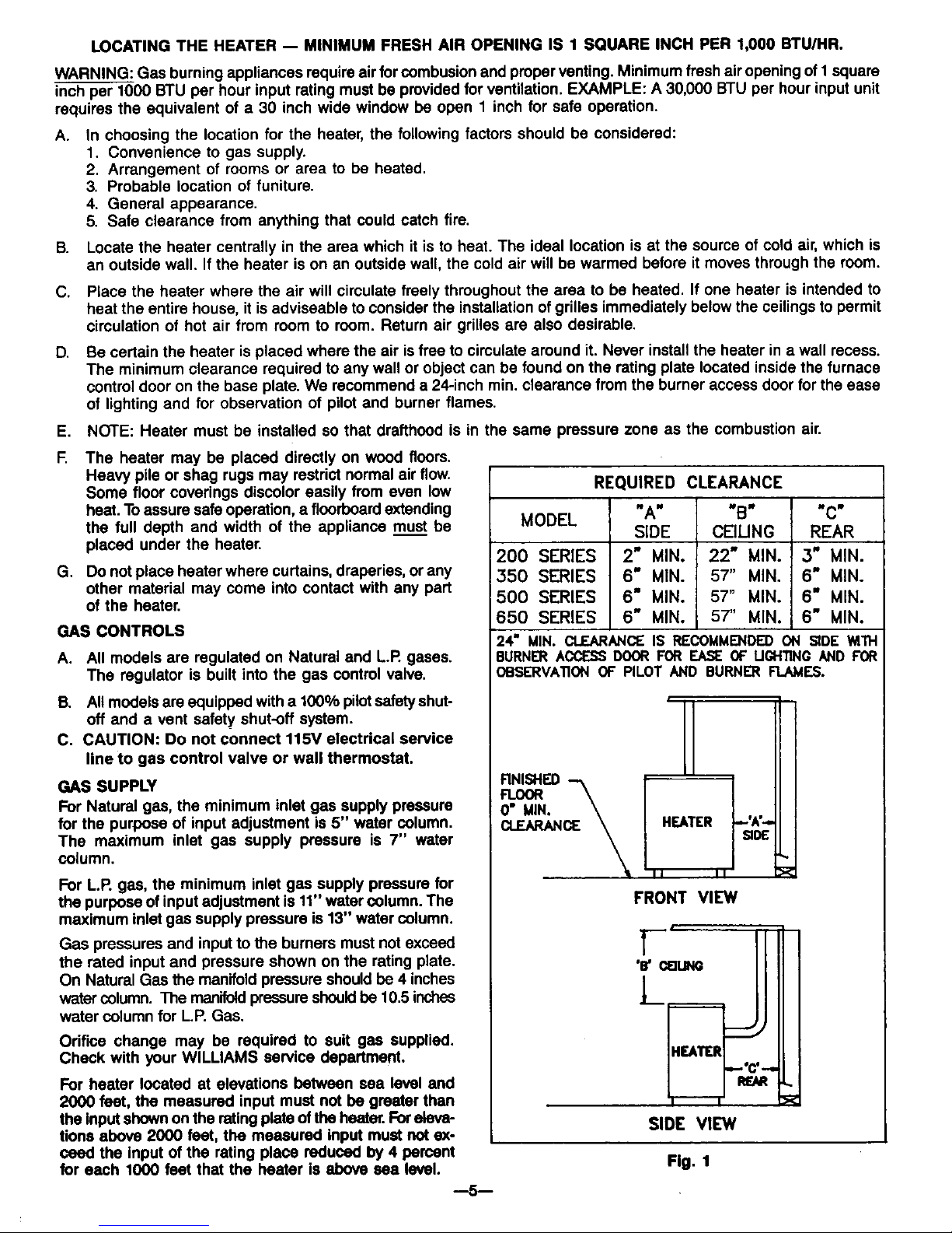
REQUIRED CLEARANCE
MODEL "A" "B" "C"
SIDE CEIUNG REAR
200 SERIES 2" MIN. 22" MIN. 3" MIN.
350 SERIES 6" MIN. 57" MIN. 6" MIN.
!500 SERIES 6" MIN. 57" MIN. 6" MIN.
650 SERIES 6" MIN. 57" MIN. 6" MIN.
=
OBSL='RVA'nONOF PILOTAND BURNER FLAMES.
o" \
FRONT VIEW
Fig. 1
--5--
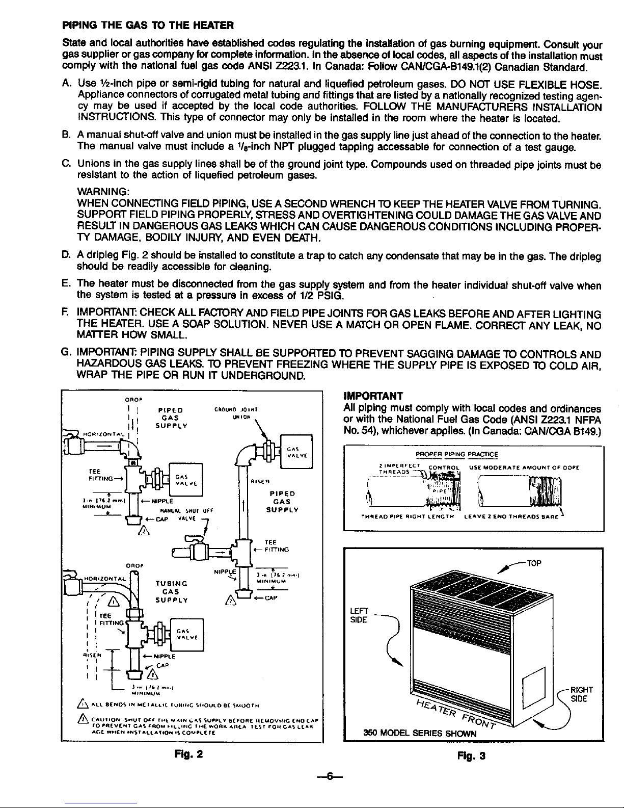
PIPING THE GAS TO THE HEATER
State and local authorities have established codes regulating the installation of gas burning equipment. Consult your
gas supplier or gas company for complete information. In the absence of local codes, all aspects of the installation must
comply with the national fuel gas coda ANSI Z223.1. In Canada: Follow CAN/CGA-B149.1(2) Canadian Standard.
A. Use 1/2-inchpipe or semi-rigid tubing for natural and liquefied petroleum gases. DO NOT USE FLEXIBLE HOSE.
Appliance connectors of corrugated metal tubing and fittings that are listed by a nationally recognized testing agen-
cy may be used if accepted by the local code authorities. FOLLOW THE MANUFACTURERS INSTALLATION
INSTRUCTIONS. This type of connector may only be installed in the room where the heater is located.
B. A manual shut-off valve and union must be installed inthe gas supply linejust ahead of the connection to the heater.
The manual valve must include a lie-inch NPT plugged tapping accessable for connection of a test gauge.
C. Unions in the gas supply lines shall be of the ground joint type. Compounds used on threaded pipe joints must be
resistant to the action of liquefied petroleum gases.
WARNING:
WHEN CONNECTING FIELD PIPING, USE A SECOND WRENCH TO KEEP THE HEATER VALVE FROM TURNING.
SUPPORT FIELD PIPING PROPERLY, STRESS AND OVERTIGHTENING COULD DAMAGE THE GAS VALVE AND
RESULT IN DANGEROUS GAS LEAKS WHICH CAN CAUSE DANGEROUS CONDITIONS INCLUDING PROPER-
TY DAMAGE, BODILY INJURY, AND EVEN DEATH.
D. A dripleg Fig. 2 should be installed to constitute a trap to catch any condensate that may be inthe gas. The dripleg
should be readily accessible for cleaning.
E. The heater must be disconnected from the gas supply system and from the heater individual shut-off valve when
the system is tested at a pressure in excess of 1/2 PSIG.
F. IMPORTANT."CHECK ALL FACTORY AND FIELD PIPE JOINTS FOR GAS LEAKS BEFORE AND AFTER LIGHTING
THE HEATER. USE A SOAP SOLUTION. NEVER USE A MATCH OR OPEN FLAME. CORRECT ANY LEAK, NO
MA'I-rER HOW SMALL.
G. IMPORTANT_ PIPING SUPPLY SHALL BE SUPPORTED TO PREVENT SAGGING DAMAGE TO CONTROLS AND
HAZARDOUS GAS LEAKS. TO PREVENT FREEZING WHERE THE SUPPLY PIPE IS EXPOSED TO COLD AIR,
WRAP THE PIPE OR RUN IT UNDERGROUND.
DROP
I 1 PIPED (;_OUN0 JOINT
I I GAS u.loN
_ PIPED
_INI_UM__IRI_PuG_J,n176 _ mini _ NIPPLE GAS
_UAL SHUt 0f_ SUPPLY
tEE
Nippt E
• ],_ I;6 Z n._,l
s
'i(,°2
' I
I I _<. cAP
MINlP,¢UM
,_ALt 81[NO_ 4_ Ml_Zat,i C IUHlld G S.OULD 0[ SMOOIH
/_ CAUIION SMUT OC, rt_. MA_ ._._ _UOI_.=V BCFOR_ N(MOVII_G (NO CAP
rO P_EVI_N_ Ga_ fROM _ _LL_tlC ! .[ WORK Ag_A _T FON GAS L_AK
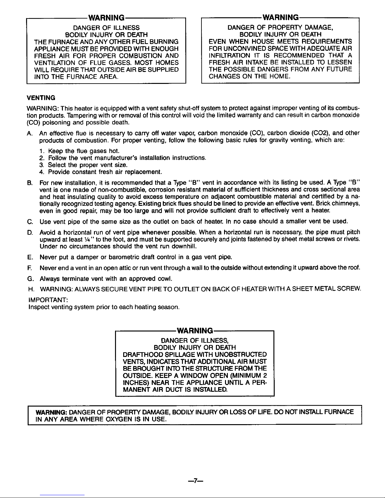
IMPORTANT
All piping must comply with local codes and ordinances
or with the National Fuel Gas Code (ANSI Z223.1 NFPA
No. 54), whichever applies. (In Canada: CAN/CGA B149.)
PROPER PIPING PR_rlC_
IMP(RF[CT CONTRO L USI_ MOO(RAT( AMOUNT OF DOPE
THR£AD P_P_ R_T L_N_T_ L_V_ _ _O TH_£AD$ _R_ _
TOP
LEFT
SIDE
350 MODEL SERIES SHOWN
Fig. 2
Rg. 3
---6--
.WARNING
DANGER OF ILLNESS
BODILY INJURY OR DEATH
THE FURNACE AND ANY OTHER FUEL BURNING
APPLIANCE MUST BE PROVIDED WITH ENOUGH
FRESH AIR FOR PROPER COMBUSTION AND
VENTILATION OF FLUE GASES. MOST HOMES
WILL REQUIRE THAT OUTSIDE AIR BE SUPPLIED
INTO THE FURNACE AREA.
WARNING
DANGER OF PROPERTY DAMAGE,
BODILY INJURY OR DEATH
EVEN WHEN HOUSE MEETS REQUIREMENTS
FOR UNCONVINED SPACE WITH ADEQUATE AIR
INFILTRATION IT IS RECOMMENDED THAT A
FRESH AIR INTAKE BE INSTALLED TO LESSEN
THE POSSIBLE DANGERS FROM ANY FUTURE
CHANGES ON THE HOME.
VENTING
WARNING: This heater isequipped with a vent safety shut-off system to protect against improper venting of its combus-
tion products. Tampering with or removal of this controlwill void the limited warranty and can result in carbon monoxide
(CO) poisoning and possible death.
A. An effective flue is necessary to carry off water vapor, carbon monoxide (CO), carbon dioxide (CO2), and other
products of combustion. For proper venting, follow the following basic rules for gravity venting, which are:
S.
C.
D.
1. Keep the flue gases hot.
2. Follow the vent manufacturer's installation instructions.
3. Select the proper vent size.
4. Provide constant fresh air replacement.
For new installation, it is recommended that a Type "B" vent in accordance with its listing be used. A Type "B"
vent is one made of non-combustible, corrosion resistant material of sufficient thickness and cross sectional area
and heat insulating quality to avoid excess temperature on adjacent combustible material and certified by a na-
tionally recognized testing agency. Existing brick flues should be lined to provide an effective vent. Brick chimneys,
even in good repair, may be too large and will not provide sufficient draft to effectively vent a heater.
Use vent pipe of the same size as the outlet on back of heater. In no case should a smaller vent be used.
Avoid a horizontal run of vent pipe whenever possible. When a horizontal run is necessary, the pipe must pitch
upward at least 1/4"to the foot, and must be supported securely and joints fastened by sheet metal screws or rivets.
Under no circumstances should the vent run downhill.
E. Never put a damper or barometric draft control in a gas vent pipe.
F. Never end a vent in an open attic or run vent through a wall to the outside without extending it upward above the roof.
G. Always terminate vent with an approved cowl.
H. WARNING: ALWAYS SECURE VENT PIPE TO OUTLET ON BACK OF HEATER WITH A SHEET METAL SCREW.
IMPORTANT:
Inspect venting system prior to each heating season.
WARNING
DANGER OF ILLNESS,
BODILY INJURY OR DEATH
DRAFTHOOD SPILLAGE WITH UNOBSTRUCTED
VENTS, INDICATES THAT ADDITIONAL AIR MUST
BE BROUGHT INTO THE STRUCTURE FROM THE
OUTSIDE. KEEP A WINDOW OPEN (MINIMUM 2
INCHES) NEAR THE APPLIANCE UNTIL A PER-
MANENT AIR DUCT IS INSTALLED.
I WARNING: DANGER OF PROPERTY DAMAGE, BODILY INJURY OR LOSS OF LIFE. DO NOT INSTALL FURNACE
IN ANY AREA WHERE OXYGEN IS IN USE.
--7--
 Loading...