

WILLETT 430 Service Manual
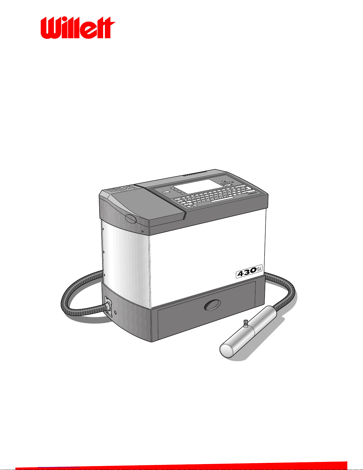
430 Ink Jet Printer
Service Manual
THE WORLD'S CODING AND LABELLING COMPANY

Contents
Issue 2
i
Part No. 306-0430-102
C
ONTENTS
PREFACE............................................................................................................................................................. VII
Introduction......................................................................................................................................................... vii
Conventions ....................................................................................................................................................... vii
Positional References..................................................................................................................................... vii
Units of Measurement .................................................................................................................................... vii
Typography..................................................................................................................................................... vii
Applicable Standards ......................................................................................................................................... vii
Installation and Inspection................................................................................................................................. viii
Mains Power Supply...................................................................................................................................... viii
Grounding...................................................................................................................................................... viii
Restrictions.......................................................................................................................................................... ix
Acknowledgements ............................................................................................................................................. ix
Associated Publications ......................................................................................................................................ix
Contact Information ............................................................................................................................................. ix
Labelling ............................................................................................................................................................... x
Hazard Information..............................................................................................................................................xi
Warning Notices ..............................................................................................................................................xi
Caution Notices ............................................................................................................................................. xiii
INSTALLATION.......................................................................................................................................................1
Introduction...........................................................................................................................................................1
Unpacking ............................................................................................................................................................2
Commissioning.....................................................................................................................................................3
Access ..............................................................................................................................................................3
Preparation for Use ..........................................................................................................................................4
Passwords ........................................................................................................................................................9
Setting up Shifts ...................................................................................................................................................9
Production Line Setup........................................................................................................................................10
Typical Installation ..........................................................................................................................................10
Throw Distance ..................................................................................................................................................11
Shaft Encoder.....................................................................................................................................................11
Internal Source ...............................................................................................................................................11
External Source ..............................................................................................................................................11
Product Sensors.................................................................................................................................................13
CONSUMABLES...................................................................................................................................................15
Ink and Solvent Storage.....................................................................................................................................15
FIRMWARE DOWNLOAD ....................................................................................................................................17
Introduction.........................................................................................................................................................17
Requirements .....................................................................................................................................................17
Windows 3.xx Procedure ...................................................................................................................................17
Checking the Communications Link ...............................................................................................................17
Windows 95/98 Procedure .................................................................................................................................18
Checking the Communications Link ...............................................................................................................18
Using Microsoft Windows 3.xx to Download Firmware ..................................................................................20
Using Microsoft Windows 95 or 98 to Download Firmware............................................................................21
Boot Monitor Recovery Procedure .................................................................................................................23
SYSTEM CALIBRATION AND TEST ...................................................................................................................25
Introduction.........................................................................................................................................................25
Earth Continuity Test..........................................................................................................................................25
Machine Power-Up.............................................................................................................................................26
Pump Zero Offset Calibration.............................................................................................................................26
Cooling Fan Check.............................................................................................................................................26

430 Ink Jet Printer Service and Maintenance Manual
ii
Issue 2
Part No. 306-0430-102
I/O Board LED Check ........................................................................................................................................ 27
Voltage Checks.................................................................................................................................................. 28
Reset Run Hours ............................................................................................................................................... 28
Gutter Fault and Charge Error Disable.............................................................................................................. 29
Set EHT Range (preliminary settings for printhead and EHT table setup)........................................................ 29
Set EHT Trip Level (for printhead setup only) ................................................................................................... 29
Filling the Ink System......................................................................................................................................... 30
Fluid Identification Number (FIN)....................................................................................................................... 31
Fill Mixer Tank ................................................................................................................................................... 31
Calibrate 285 V Rail........................................................................................................................................... 32
VMS Calibration................................................................................................................................................. 32
Nozzle Flush ...................................................................................................................................................... 33
Strobe LED Check ............................................................................................................................................. 33
Ink Jet Alignment ............................................................................................................................................... 33
Head Heater Temperature and Ink Pressure .................................................................................................... 34
Modulation Calibration (Manual)........................................................................................................................ 35
Phase Profile Adjustment ..................................................................................................................................37
Phase Offset Calibration.................................................................................................................................... 37
Print Charge Value Calibration .......................................................................................................................... 37
Setting EHT Tables for Printing ......................................................................................................................... 38
Clean Shutdown Check ..................................................................................................................................... 38
Set EHT Trip Level (Normal Operation) ............................................................................................................ 39
EHT Trip Test .................................................................................................................................................... 39
Print Height Test ................................................................................................................................................ 39
Restore Calibration Parameters ........................................................................................................................40
Enable Gutter Detect and Charge Check .......................................................................................................... 40
Ink Viscosity Measurement................................................................................................................................ 41
Temperature/Viscosity Graphs ...................................................................................................................... 41
CIJ MK 390ID Black....................................................................................................................................... 41
CIJ MK 3903F Red ........................................................................................................................................ 42
CIJ MK 3930F Black ......................................................................................................................................42
CIJ EA 3969H Black ...................................................................................................................................... 43
TECHNICAL DESCRIPTION................................................................................................................................ 45
Main Assemblies................................................................................................................................................ 46
Cabinet .............................................................................................................................................................. 46
Top Cover ...................................................................................................................................................... 46
Side Covers.................................................................................................................................................... 47
Base ............................................................................................................................................................... 47
Printhead ........................................................................................................................................................... 48
Construction ................................................................................................................................................... 49
Electronics System ............................................................................................................................................ 51
Control Panel .................................................................................................................................................51
Connector Panel ............................................................................................................................................ 53
Control Electronics............................................................................................................................................. 55
General .......................................................................................................................................................... 55
CPU Board ..................................................................................................................................................... 56
I/O Board........................................................................................................................................................ 62
Ink Pump Motor Driver Board ........................................................................................................................ 74
PSU Board......................................................................................................................................................... 77
General Specification..................................................................................................................................... 77
Output Specification....................................................................................................................................... 77
Electronics Modules........................................................................................................................................... 78
EHT Module ................................................................................................................................................... 78
Electronics Compartment Cooling Fan .......................................................................................................... 78
Ink System Pump........................................................................................................................................... 78
Mains Input Circuit ......................................................................................................................................... 79

Contents
Issue 2
iii
Part No. 306-0430-102
Ink System..........................................................................................................................................................80
General ...........................................................................................................................................................80
Solenoid Valves..............................................................................................................................................81
V1 Solvent Top-up Valve (located at the solvent top-up reservoir) ............................................................81
V2 Ink Top-up Valve (located at the ink reservoir)......................................................................................81
V3 VMS Diverter Valve (located on the FMS ink system) ..........................................................................81
V6 Feed Valve (located on the FMS ink system)........................................................................................81
V7 Flush Valve (located on the FMS ink system) .......................................................................................81
V8 Gutter Valve (located on the FMS ink system)......................................................................................82
V11 Jet Valve (located in the printhead).....................................................................................................82
V12 Bleed Valve (located in the printhead) ................................................................................................82
Top Up and Ink Reservoirs.............................................................................................................................82
Ink System Filters ...........................................................................................................................................82
Main System Filter (located inside the filter compartment).........................................................................82
Pre Pump Filter (located inside the filter compartment) .............................................................................83
Pre Head Filter (located below the FMS printhead connection manifold) ..................................................83
Nozzle Filter (located behind the nozzle in the printhead)..........................................................................83
Flush Filter (located near flush pump) ........................................................................................................83
VMS Filter (located inside FMS top box) ....................................................................................................83
Fluid Management System (FMS)..................................................................................................................84
Viscosity Monitoring System (VMS) Chamber (located inside the FMS top box).......................................84
Venturi (Jet Pump) (located inside the FMS top box) .................................................................................85
Pressure Transducer (located on the FMS connect manifold) ...................................................................85
Ink System Pump (located in the base of the machine) .............................................................................85
Flush Pump (located close to the FMS)......................................................................................................85
Printhead Operation ...........................................................................................................................................86
Ink Jet Information ..........................................................................................................................................86
Droplet Charging ............................................................................................................................................86
Droplet Deflection ...........................................................................................................................................87
Ink System Operation.........................................................................................................................................88
Function ..........................................................................................................................................................88
Operation........................................................................................................................................................88
Viscosity Monitoring System Sequence .........................................................................................................89
Clean Start Jet Sequence...............................................................................................................................91
Quick Start Jet Sequence...............................................................................................................................93
Clean Stop Jet Sequence...............................................................................................................................94
Quick Stop Jet Sequence ...............................................................................................................................96
Nozzle Flush ...................................................................................................................................................96
Ink Addition to Mixer Tank ..............................................................................................................................97
Top Up Addition to Mixer Tank .......................................................................................................................98
SYSTEM SOFTWARE...........................................................................................................................................99
Introduction.........................................................................................................................................................99
Using the Menus.............................................................................................................................................99
Messages Menu ...............................................................................................................................................100
Editor Menu ......................................................................................................................................................101
User Fields Menu .............................................................................................................................................101
Print Menu ........................................................................................................................................................102
Password Menu................................................................................................................................................102
System Menu ...................................................................................................................................................103
Configure Menu................................................................................................................................................105
Calibrate Menu .................................................................................................................................................106
Data Logging Menu ..........................................................................................................................................108
DISASSEMBLY AND ASSEMBLY.....................................................................................................................109
Introduction.......................................................................................................................................................109

430 Ink Jet Printer Service and Maintenance Manual
iv
Issue 2
Part No. 306-0430-102
I/O Board ......................................................................................................................................................... 110
Removal ....................................................................................................................................................... 110
Installation .................................................................................................................................................... 111
Calibration .................................................................................................................................................... 111
CPU Board....................................................................................................................................................... 112
Removal ....................................................................................................................................................... 112
Installation .................................................................................................................................................... 112
Power Supply Unit ........................................................................................................................................... 113
Removal ....................................................................................................................................................... 113
Installation .................................................................................................................................................... 113
PSU Module Fuse Replacement.................................................................................................................. 114
LCD and Backlight ........................................................................................................................................... 115
Removal ....................................................................................................................................................... 115
Installation .................................................................................................................................................... 116
Keypad............................................................................................................................................................. 116
Removal ....................................................................................................................................................... 116
Installation .................................................................................................................................................... 116
Ink and Top Up Reservoir Sensor ................................................................................................................... 117
Removal ....................................................................................................................................................... 117
Installation .................................................................................................................................................... 117
Exchanging the Sensor and LED................................................................................................................. 117
Mains Inlet Connector...................................................................................................................................... 119
Removal ....................................................................................................................................................... 119
Installation .................................................................................................................................................... 120
Mains Switch.................................................................................................................................................... 120
Removal ....................................................................................................................................................... 120
Installation .................................................................................................................................................... 120
Fluid Management System (FMS)................................................................................................................... 121
Removal ....................................................................................................................................................... 121
Installation .................................................................................................................................................... 122
Ink System Pump............................................................................................................................................. 123
Removal ....................................................................................................................................................... 123
Installation .................................................................................................................................................... 124
Main Filter ........................................................................................................................................................ 125
Removal ....................................................................................................................................................... 125
Installation .................................................................................................................................................... 125
Flush Pump...................................................................................................................................................... 126
Removal ....................................................................................................................................................... 126
Installation .................................................................................................................................................... 126
Solenoid Valves ............................................................................................................................................... 127
Removal ....................................................................................................................................................... 127
Installation .................................................................................................................................................... 127
Fan................................................................................................................................................................... 128
Removal ....................................................................................................................................................... 128
Installation .................................................................................................................................................... 128
Fan Failure Card.............................................................................................................................................. 129
Removal ....................................................................................................................................................... 129
Installation .................................................................................................................................................... 129
EHT Module..................................................................................................................................................... 130
Removal ....................................................................................................................................................... 130
Installation .................................................................................................................................................... 130
Head Manifold.................................................................................................................................................. 131
Removal ....................................................................................................................................................... 131
Installation .................................................................................................................................................... 132
Phase Detector ................................................................................................................................................ 133
Removal ....................................................................................................................................................... 133
Installation .................................................................................................................................................... 134

Contents
Issue 2
v
Part No. 306-0430-102
EHT Block ........................................................................................................................................................135
Removal........................................................................................................................................................135
Installation.....................................................................................................................................................136
Nozzle Assembly..............................................................................................................................................137
Removal........................................................................................................................................................137
Installation.....................................................................................................................................................138
RS232 Jumper .................................................................................................................................................139
Installation.....................................................................................................................................................139
Removal........................................................................................................................................................139
Umbilical...........................................................................................................................................................141
PREVENTATIVE MAINTENANCE SCHEDULE.................................................................................................143
TROUBLESHOOTING ........................................................................................................................................145
Introduction.......................................................................................................................................................145
Fault Finding.....................................................................................................................................................146
Printer Fails to Initialise ................................................................................................................................146
Display Faults...................................................................................................................................................149
Backlight .......................................................................................................................................................149
Display ..........................................................................................................................................................150
Keypad Faults...............................................................................................................................................150
Display Icons ....................................................................................................................................................151
Mixer Tank Level High..................................................................................................................................155
CLEANING AND ADJUSTMENT........................................................................................................................157
Valve Cleaning .................................................................................................................................................157
VMS Inlet Restrictor Cleaning ..........................................................................................................................158
VMS Outlet Cleaning........................................................................................................................................159
Umbilical Purge ................................................................................................................................................160
Printhead Alignment.........................................................................................................................................161
ILLUSTRATED PARTS LIST..............................................................................................................................165
How to Use This Parts List ...............................................................................................................................165
Optional Parts and Accessories .......................................................................................................................165
430 Ink Jet Printer ............................................................................................................................................166
Stand and Traffic Light System ........................................................................................................................167
Options and Accessories .................................................................................................................................168
General Spare Parts and Tools........................................................................................................................169
Documentation .................................................................................................................................................169
Major Sub-Assemblies .....................................................................................................................................170
Top Moulding Ink System Components ...........................................................................................................171
Top Moulding, Keypad and LCD ......................................................................................................................172
Baffle Plate Assembly ......................................................................................................................................174
Printhead Assembly .........................................................................................................................................175
Base Moulding and Cabinet .............................................................................................................................177
Mains Plate Assembly ......................................................................................................................................179
Ink System........................................................................................................................................................181
APPENDIX B ...........................................................................................................................................................1
Earlier 430 Model .................................................................................................................................................1
Ink System............................................................................................................................................................1
General .............................................................................................................................................................1
Flush Tank............................................................................................................................................................2
Removal............................................................................................................................................................2
Installation.........................................................................................................................................................2
Earlier 430 Illustrated Parts List ...........................................................................................................................3
Ink System ........................................................................................................................................................3

430 Ink Jet Printer Service and Maintenance Manual
vi
Issue 2
Part No. 306-0430-102

Preface
Issue 2
vii
Part No. 306-0430-102
P
REFACE
Introduction
Welcome to the Service Manual for the Willett 430 Inkjet printer.
This manual is intended as a reference guide for trained service personnel and contains the following
information:
•
installation and calibration instructions;
•
disassembly and reassembly instructions for field-replaceable components;
•
a technical description of the principles of operation of the printer;
•
a troubleshooting guide;
•
a quick reference guide to the control software which describes the function of each menu item.
Conventions
Positional References
Unless stated to the contrary, positions and directions such as left, right, front, rear, clockwise and anticlockwise
are given with respect to the printer when viewed from the front.
Units of Measurement
This handbook uses SI units of measurement and their imperial equivalents.
Typography
The names of menu options are presented in
bold
typeface. Cross-references are presented on
bold, italic
typeface.
Applicable Standards
Willett Limited is a BS5750/ISO9000 approved company (certification number FM14003 dated 9 December
1991).
The 400 Series Continuous Ink Jet (CIJ) printers conform to the following legislation:
EN55022: 1987 - Emissions.
IEC801: parts 2 to 6 inclusive - Immunity standards.
Machinery directive 89/392/EEC - Essential health and safety.
BS5304 - Machinery design.
EN60204 (BS2771) - Electrical safety in machinery.
EN292: 1991 - Safety of machinery.
EN60950 - Safety standards of Information Technology (IT) equipment.

430 Ink Jet Printer Service and Maintenance Manual
viii
Issue 2
Part No. 306-0430-102
Installation and Inspection
The equipment described in this handbook must be installed and subsequently inspected at the recommended
intervals by qualified service and maintenance personnel.
Mains Power Supply
Ensure that the mains electrical supply is within the range indicated by the label adjacent to the mains inlet on
the printer. If the voltage ratings differ, do not use the printer until you have consulted your local supplier.
Use only the mains power cable supplied with the printer. This cable must terminate in an approved, three-pole,
mains plug which has a protective ground conductor.
Keep electrical power cables, sockets and plugs clean and dry at all times.
Grounding
The equipment must be connected only to an a.c. power supply, which has a protective ground conductor in
accordance with IEC requirements or applicable local regulations. Any interruption of the protective ground
conductor or disconnection of the protective ground terminal may render the apparatus dangerous.

Preface
Issue 2
ix
Part No. 306-0430-102
Restrictions
The information contained herein shall not be reproduced in whole or part without the manufacturer’s prior
written approval.
The manufacturer reserves the right to make changes in specifications and other information contained in this
document without prior notice. The reader should in all cases consult the manufacturer to determine whether
any such changes have been made.
Copyright © Willett Limited 2001.
Printed in the UK. March 2001.
Acknowledgements
The Willett name and Willett logo are trademarks of Willett Limited.
Associated Publications
Willett 430 Ink Jet Printer Instructions for Use
Part Number 306-0430-101.
Contact Information
Willett Limited
Cronin Road
Corby
Northamptonshire
NN18 8AQ
England
Phone +(44) 1536 400777
Fax +(44) 1536 400888
http://www.willett.com
430 Ink Jet Printer Service and Maintenance Manual
x
Issue 2
Part No. 306-0430-102
Labelling
The following labels appear on the 430 Ink Jet printer:
PRINT TRIGGER 1 SHAFT ENCODER
PRINT TRIGGER 2 STATUS O/P RID
I/O A I/O A COMM2
COMM 1
No smoking
or naked lights
Highly
flammable
SERIAL No.
DESIGNED AND MANUFACTURED BY
WILLETT SYSTEMS LTD. CORBY ENGLAND TEL: 01536 400777
WHOSE QUALITY SYSTEM IS REGISTERED BY BSI
TO ISO 9001 CERT No FM 14003
geprüfte
Sicherheit
TÜV
Rheinland
Product safety
UNDER CERTAIN OPERATING CONDITIONS
THERE COULD BE SOLVENT EMISSIONS
FROM THIS MACHINE.
ENSURE THAT THE MACHINE IS OPERATED
IN A WELL VENTILATED AREA AND IF
NECESSARY MONITOR CONCENTRATIONS
INTHE IMMEDIATE VICINITY.
W A R N I N G
OPERATING VOLTAGE
TENSION SECTEUR
BETRIEBSSPANNUNG
FREQUENCY
FREQUENCE
FREQUENZ
CURRENT
COURANT ASSIGNÉ
NENNSTROM
POWER
CONSOMMATION
NENNLEISTUNG
FUSES
FUSIBLES
SICHERUNG
110/230 Vac 1
50/60Hz
2A
160W
T5A/T3.15A
CAUTION : DOUBLE POLE/NEUTRAL FUSING
ATTENTION : PROTECTION BIPOLAIRE
ACHTUNG : 2-POLIG ABGESICHERT
ISOLATE THIS UNIT BEFORE MAKING
ANY INTERNAL ADJUSTMENTS
DEBRANCHER L'APPAREIL AVANT
TOUT INTERVENTION INTERNE
VOR ÖFFNEN DES GEHÄUSES
NETZSTECKER ZIEHEN
Ø

Preface
Issue 2
xi
Part No. 306-0430-102
Hazard Information
This section contains important hazard notices. You must read these notices before using the printer.
The hazard information is prioritised into typographically distinct warning and caution notices as follows:
WARNING NOTICES
Warning notices denote a potential hazard to the health and safety of users. These
notices clearly state the nature of the respective hazard and the means by
which it can be avoided.
Warning notices, together with the warning symbol shown on the left, appear in full in the
preliminary pages and at their points of application in the manual. They are presented in
the typographical style of this notice.
Caution Notices
Cautionary notices denote a potential hazard to the physical integrity of equipment/software but not a
danger to personnel. These notices clearly state the nature of the hazard and the means by
which it can be avoided.
Cautionary notices appear in full in the preliminary pages and at their points of application in the
manual. They are presented in the typographical style of this notice.
Warning Notices
WARNING - LETHAL VOLTAGES
Lethal voltages are present within this equipment when it is connected to the mains
electrical supply. Only trained and authorised personnel may carry out maintenance work.
Observe all statutory electrical safety codes and practices. Unless it is necessary to run
the printer, disconnect the printer from the mains electrical supply before removing the
covers or attempting any service or repair activity, otherwise death or
personal injury may result.
WARNING - HANDLING INK, SOLVENT AND TOP-UP
The ink, solvent and top-up are irritating to the eyes and respiratory system. To prevent
personal injury when handling these substances:
Always wear protective clothing and rubber gloves.
Always wear goggles with side-shields or a face mask. It is also advisable to wear safety
glasses when carrying out maintenance.
Apply barrier hand cream before handling ink.
If ink or top-up contaminates the skin, wash immediately with soapy water. DO NOT use
washdown or solvent to clean ink stains from the skin.

430 Ink Jet Printer Service and Maintenance Manual
xii
Issue 2
Part No. 306-0430-102
WARNING - RISK OF PERSONAL INJURY
To avoid spillage of ink or top-up, do not remove the foil seal from the bottle prior to
replenishing the ink or top-up reservoir.
WARNING - FIRE AND HEALTH HAZARD
The ink, solvent and top-up are volatile and flammable. They must be stored and handled
in accordance with local regulations.
Do not smoke or use a naked flame in the vicinity of these substances.
Immediately after use remove any tissue or cloths that become saturated with these
substances. Dispose of all such items in accordance with local regulations.
In the event that any ink, solvent or top-up container is not completely empty after use, it
should be resealed. Only full bottles are recommended for use when replenishing ink or
top ups; partially filled bottles should be disposed of in accordance with local regulations.
WARNING - WASTE INK
When setting up the nozzle, direct the ink stream into a beaker or suitable container. To
avoid contamination of the ink supply in the printer, do not re-use any ink collected in this
way. Dispose of all waste ink in accordance with local regulations.
WARNING - VAPOUR HAZARD
Prolonged breathing of top-up or cleaning fluid vapour may cause drowsiness and/or
effects similar to alcoholic intoxication. Use only in open, well-ventilated areas.
WARNING - FUSES FIRE HAZARD
To ensure continued protection against the risk of fire, replace fuses only with the
specified type and rating.
WARNING - TOXIC HAZARD
The cleaning agent is poisonous if taken internally. Do not drink. Seek medical attention
immediately if ingested.
WARNING - HANDLING CLEANING AGENT
The cleaning agent is irritating to the eyes and respiratory system. To prevent personal
injury when handling this substance:
Always wear protective rubber gloves and clothing.
Always wear goggles with side-shields or a face mask. It is also advisable to wear safety
glasses when carrying out maintenance.
Apply barrier hand cream before handling ink.
If cleaning agent contaminates the skin, rinse off with running water for
at least 15 minutes.
Preface
Issue 2
xiii
Part No. 306-0430-102
WARNING - FIRE AND HEALTH HAZARD
The cleaning agent is volatile and flammable. It must be stored and handled in accordance
with local regulations.
Do not smoke or use a naked flame in the vicinity of the cleaning agent.
Immediately after use remove any tissue or cloths that become saturated with cleaning
agent. Dispose of all such items in accordance with local regulations.
WARNING - PERSONAL INJURY
Airborne particles and substances are a health hazard. Do not use high pressure
compressed air for cleaning purposes.
WARNING - EARTH CONTINUITY
To ensure safe earthing the resistance between the mains lead earth wire and the test
points must be less than 1 Ω.
WARNING - INK/SOLVENT SPILLAGE HAZARD
Ensure that the top cover of the machine is lowered fully into the correct working position
and the filler tubes are correctly located in the ink/top up reservoir before continuing,
otherwise there is a risk of ink spillage.
WARNING - HANDLING INK, SOLVENT AND TOP-UP
A high ac voltage is present at the inverter and backlight.
Extreme caution is required when diagnosing failure in these areas.
Caution Notices
Caution - Equipment Damage
Only Willett trained personnel my carry out installation and maintenance work. Any such work
undertaken by unauthorised personnel may damage the printer and will invalidate the warranty.
Caution - Equipment Damage
Take care not to damage the printer base, internal components or wiring when removing or
refitting the side covers
Caution - Equipment Failure
Ensure that the top cover is lowered to the correct working position and that the filler tubes are correctly
located in the ink and solvent top-up reservoirs before proceeding.
Caution - Degraded Performance
Machine functions that only Willett trained personnel can access are set at Password Level 3
(MASTER password), these functions must not be given as customer options.

430 Ink Jet Printer Service and Maintenance Manual
xiv
Issue 2
Part No. 306-0430-102
Caution - Electrostatic Sensitive Devices
The printed circuit boards contain static sensitive devices. A suitably grounded, antistatic wrist strap
must be worn when working on or handling printed circuit boards.
Caution - False Readings
To avoid the risk of false readings, the pump zero offset should only be calibrated when there is no ink
in the system and the pump is off.
Caution - Print Quality
To ensure high print quality, ink viscosity must be checked and must be correct prior to attempting
modulation calibration.
Caution – Incorrect Measurement
If the temperature compensation factor is not used, the end result could be incorrect
by as much as 40%.
Caution - Equipment Damage
Never attempt to bend the gutter. Its position is fixed.
Caution - Damage to Charge Electrode
Take care not to deform the charge electrode slot when rotating the charge electrode.
Caution - Charge Cable
Ensure that the charge cable is not pulled out of its position in the rear face of the
deflector block assembly.
Caution - Equipment Damage
Never attempt to bend the gutter. It is in a fixed position.
Caution - Equipment Damage
The I/O Board LEDS connector must not be used to drive anything other than LEDs as specified
otherwise damage may occur.
Caution - Excessive Use of Top-Up or Solvent
As solvent is used during the stop cycle, repeatedly stopping and starting the printer can lead to
excessive use of top-up or solvent and may lead to a Mixer Tank High error.
Caution - Quick Stop
After a Quick Stop machine should not be left in this state for any length of time as drying ink may
make restarting difficult

Preface
Issue 2
xv
Part No. 306-0430-102
Caution - Equipment Damage
To avoid the risk of overfilling or spillage, never replenish ink or top-up unless the relevant
low icon is shown.
Ensure that ink bottle is completely empty before removing.
Caution - Equipment Damage
Do not fit or remove any connector on the printer whilst power is on, otherwise the printer
may be damaged.
Caution - Cleaning Materials
To avoid damage to the printer components use only soft brushes and lint free cloths for cleaning. Do
not use high pressure air, cotton waste or abrasive materials.
Caution - Equipment Damage
Ensure that the cleaning agent is compatible with the ink used before carrying out printhead cleaning
otherwise the printhead may be damaged.
Caution - Equipment Damage
The printhead must be completely dry before attempting to start the printer otherwise the printhead
may be damaged.
Caution - Printer Overheating
Report all overheating incidents to a maintenance engineer.
Caution - Risk of Data Loss
Ensure the correct message name is selected for message deletion as no message selection
confirmation prompt is given.
Caution - Risk of Data Loss
All messages apart from the TEST MESSAGE will be deleted.
Caution - Risk of Data Loss
The Clear Message option, when selected, does not ask for confirmation to
clear the message.
Caution - Risk of Data Loss
The Delete user field option does not ask for confirmation to delete a User Field.

430 Ink Jet Printer Service and Maintenance Manual
xvi
Issue 2
Part No. 306-0430-102

Installation: Introduction
Issue 2
1
Part No. 306-0430-102
I
NSTALLATION
Introduction
The printer is tested and commissioned prior to despatch to the customer. If further on-site commissioning is
required, refer to the
Troubleshooting
section of this manual.
Each installation must be approached on an individual basis due to variations in production line build
specifications. Supposedly identical production lines can vary significantly due to customer requirements or
modifications.
Each installation must be preceded by a site survey to establish the necessary information relevant to the
production line and printer. In some cases it may be impossible to install a printer; it is therefore of vital
importance that all the installation criteria are met before attempting installation. The site survey form must be
completed as fully as possible by the sales engineer.
Missing or ambiguous information should be clarified by telephone or fax prior to the installation procedure.
WARNING - LETHAL VOLTAGES
Lethal voltages are present within this equipment when it is connected to the mains
electrical supply. Only trained and authorised personnel may carry out maintenance work.
Observe all statutory electrical safety codes and practices. Unless it is necessary to run
the printer, disconnect the printer from the mains electrical supply before removing the
covers or attempting any service or repair activity, otherwise death or
personal injury may result.
Caution - Equipment Damage
Only Willett trained personnel may carry out installation and maintenance work. Any such work
undertaken by unauthorised personnel may damage the printer and will invalidate the warranty.
430 Ink Jet Printer Service and Maintenance Manual
2
Issue 2
Part No. 306-0430-102
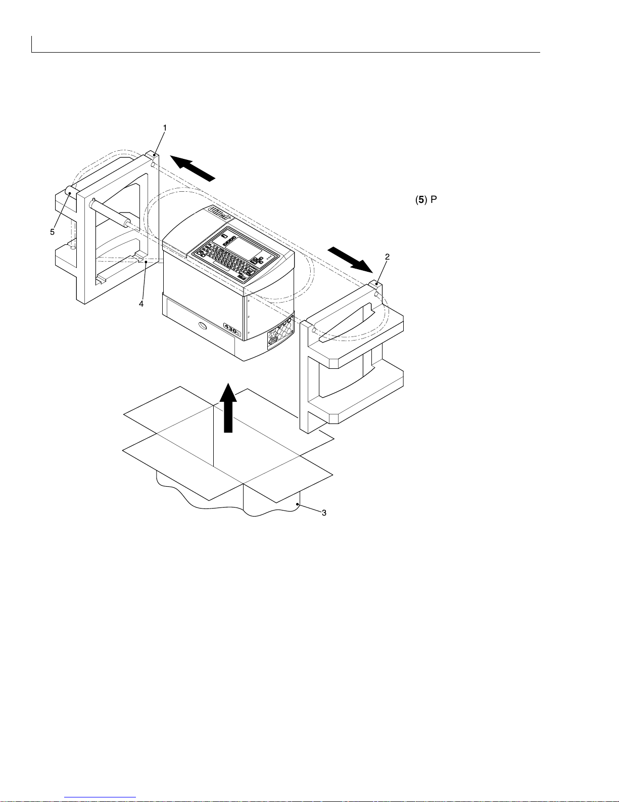
Unpacking
(1) Left-hand Insert
(2) Right-hand Insert
(3) Carton
(4) Umbilical
1
2
3
4
5
(5) Printhead
Figure 1 Unpacking the Printer
1
Open the top flaps of the carton and gently pull the complete machine and inserts (1 and 2) upwards from
the carton.
2
Place the printer and inserts on a clean level surface.
3
Remove the printhead (5) from the left-hand insert (1).
4
Remove the umbilical (4) from its transit routeing.
5
Remove the left-hand insert and right-hand insert (2).
6
Place the printer on a clean level surface for commissioning.
Installation: Commissioning
Issue 2
3
Part No. 306-0430-102
Commissioning
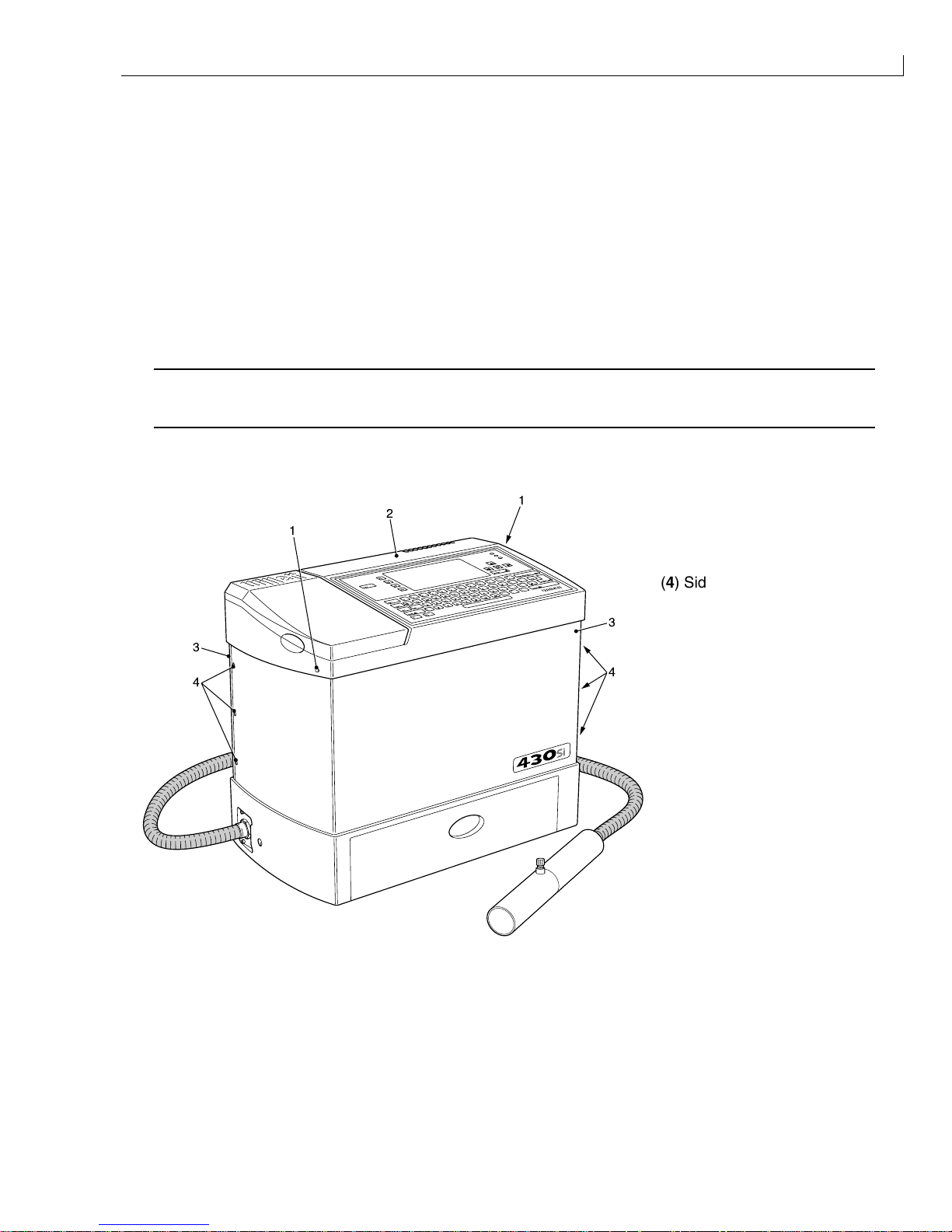
Access
1
Tighten the two top cover fasteners (1) until they release the top cover catches (the top cover (2) will raise
slightly).
2
Unscrew both top cover fasteners, leaving them captive.
3
Raise the top cover until the spring loaded locating pins on the extender legs slot into their respective
locating holes.
4
Turn the six side cover fasteners (4) one quarter turn counter-clockwise. These fasteners are captive in their
respective side covers (3).
Caution - Equipment Damage
Take care not to damage the printer base, internal components or wiring when removing or refitting the
side covers
5
Remove the side covers, noting their orientation for refitting.
(1) Top Cover Fasteners
(2) Top Cover
(3) Side Cover
1
2
1
3
4
3
4
(4) Side Cover Fasteners
Figure 2 Cover Fastener Location
430 Ink Jet Printer Service and Maintenance Manual
4
Issue 2
Part No. 306-0430-102
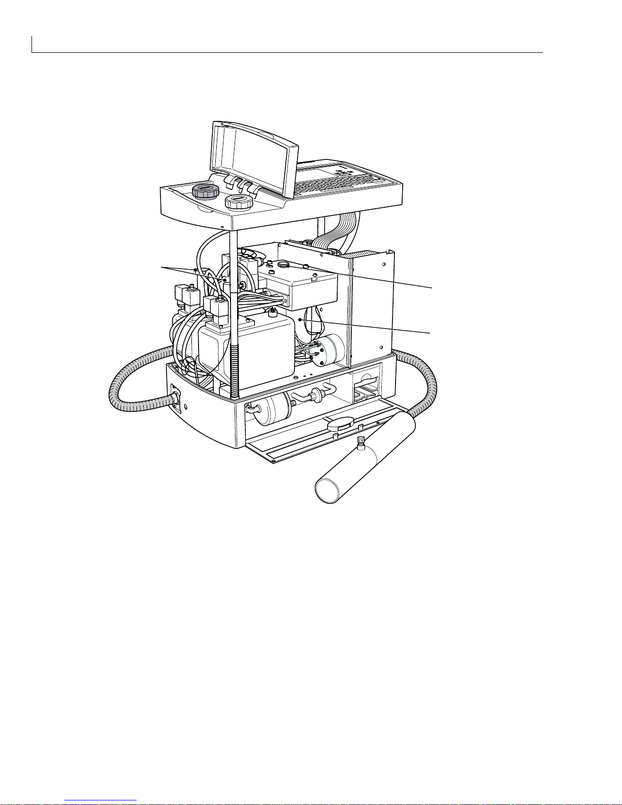
Preparation for Use
(1) Filler Plug
(2) Ink Mixer Bowl
3
2
1
(3) Filler Tubes
Figure 3 Ink Mixer Bowl Filler Plug Location
1
Remove and retain the black rubber shipping cap from the breather tube.
2
Fit the breather tube to the blue fitting located on the underside of the top cover.
3
Ensure that the correct fuses (Figure 4 (2)) are fitted for the local mains electrical supply as shown in the
table below.
Installation: Commissioning
Issue 2
5
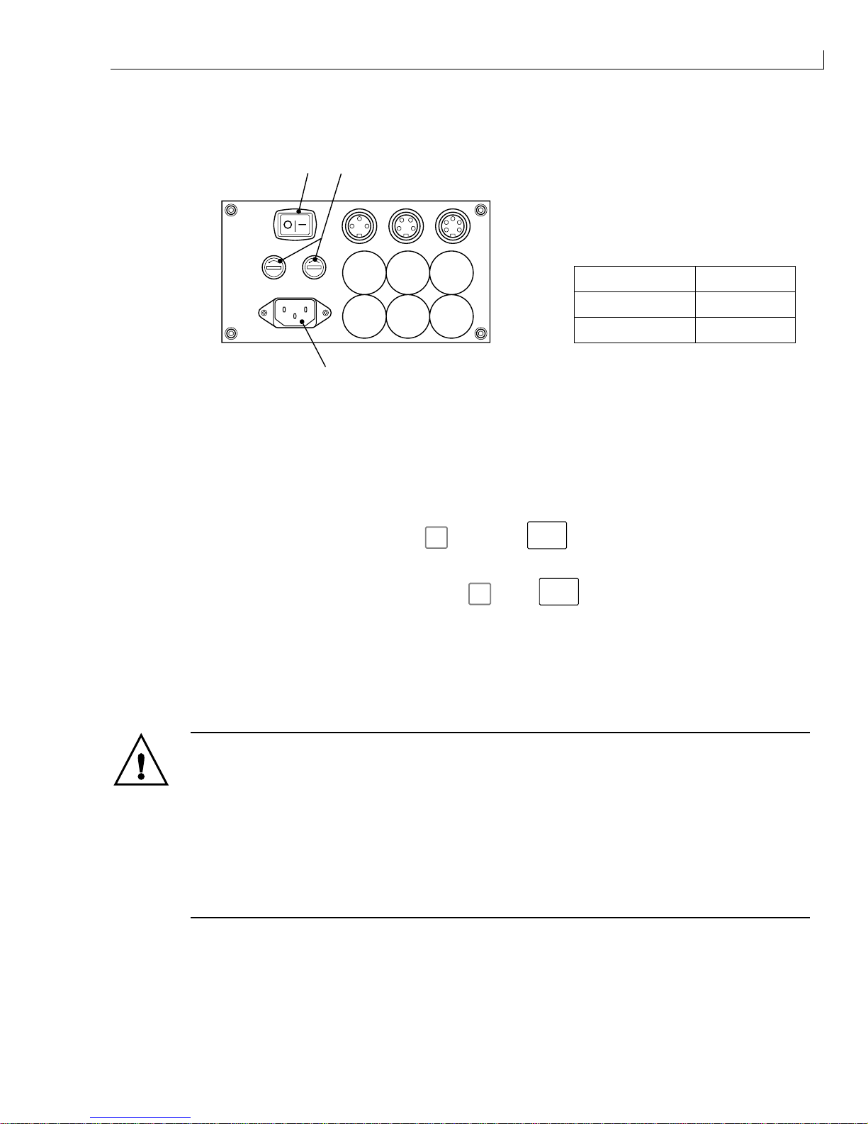
Part No. 306-0430-102
(1) On/Off switch
(2) Supply fuse holder
(3) Mains inlet socket
Mains Voltage Fuse Rating
110 V AC 5 A
230 V AC 3.15 A
3
21
PRINT TRIGGER 1 SHAFT ENCODER COMM 1
Figure 4 Connector Panel and Fuse Ratings
4
Connect the mains electrical supply to the mains inlet socket (3) and set the On/Off switch (1) to I (On). The
printer PSU will automatically detect and adjust to the mains voltage.
The printer remains uninitialised and the quick screen is displayed on the LCD panel.
5
If
nothing is visible on the LCD display, press f3, then press
ctrl
and L. Press any key to set the
contrast when the LCD is visible.
6
If the menu system cannot be accessed by pressing
f3
, press
ctrl
and Z, then P, enter the MASTER
password and repeat step 6.
7
Access the
Password
menu and enter the MASTER password.
8
Remove the filler plug (Figure 3 (1)) and prime the mixer bowl (2) with approximately 250 ml of the correct
ink using a syringe and a length of 40 mm x 6 mm tube. The Ink Out icon will cease to be displayed when
approximately 250 ml is added to the mixer bowl.
WARNING - HANDLING INK, SOLVENT AND TOP-UP
The ink, solvent and top-up are irritating to the eyes and respiratory system. To prevent
personal injury when handling these substances:
Always wear protective clothing and rubber gloves.
Always wear goggles with side-shields or a face mask. It is also advisable to wear safety
glasses when carrying out maintenance.
Apply barrier hand cream before handling ink.
If ink or top-up contaminates the skin, wash immediately with soapy water. DO NOT use
washdown or solvent to clean ink stains from the skin.
9
Ensure that the complete 250 ml is added before proceeding.
10
Refit the filler plug (1) to the top of the FMS.
11
Refit the side covers, ensure that the orientation is correct as noted, secure the side cover fasteners
(Figure 3 (4)).

430 Ink Jet Printer Service and Maintenance Manual
6
Issue 2
Part No. 306-0430-102
12
Push in the locating pins on each of the extender legs and lower the top cover (Figure 2 (2)) into position. It
will be necessary to exert a small amount of pressure to locate the cover properly.
Caution - Equipment Failure
Ensure that the top cover is lowered to the correct working position and that the filler tubes are correctly
located in the ink and solvent top-up reservoirs before proceeding.
13
Pour the remaining ink into the ink reservoir (4-slot spider with black cap).
14
Fill the top-up reservoir (3-slot spider with white cap) with 1 litre of the appropriate top-up solvent.
15
From the
System
menu, select
Fill Mixer Tank
and press
enter
. The pump will start and the mixer tank
will fill. The pump will stop automatically when the ink level is satisfactory.
16
Remove the printhead cover, nozzle seal and gutter plug (retain the seal and plug for refitting if the machine
has to be transported).
17
Mount the printhead to a suitable support.
18
Disable Gutter Detect as follows:
a
Access the
System
menu.
b
Select
Gutter Fault Shutdown Disable
.
c
In the
Machine Control
sub-menu set
Gutter Fault
to
Disable
and press
enter
.
19
Disable Charge Check as follows:
a
Access the
System
menu.
b
Select Charge Error Shutdown Disable.
c
In the
Machine Control
sub-menu set
Charge
Error to
Disable
and press
enter
.
20
Press
f1
to start the jet.
21
Ensure that the printhead alignment is correct. If adjustment is required then refer to
Printhead
Alignment,
page 161.
22
From the
Machine Control
sub-menu:
a
Select
Gutter fault
to enable Gutter Detect.
b
Select
Charge Error
to enable Charge Check.
23
Fit the printhead cover.
24
Input a message. The message must contain a six-digit incrementing counter.
25
Place an earthed print collector dish under the printhead.
26
Select the created message for printing.
27
Select Continuous Print mode:
a
From the
Print
menu, select
Continuous Print
.
b
From the Continuous print sub-menu set
Continuous mode
to Time Mode and Time Mode Delay to 50.
Installation: Commissioning
Issue 2
7
Part No. 306-0430-102
28
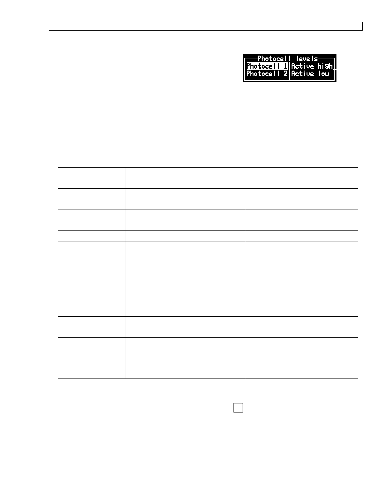
From the
Configure
menu, select
Photocell Levels
and set
the state of the
photocell 1 level
to
Active high
or
Active Low
as required.
29
The printer should now be printing continuously. Let the printer complete a minimum of 250 000 prints. Use
the counter to monitor the number of messages printed. Monitor the printer to ensure that the system
functions correctly.
30
At regular intervals access the
Calibrate
menu and select the Diagnostics Screen. Monitor the machine
parameters and check that they remain stable. Typical Diagnostics Screen values are shown in the table
below.
Note: The values provided are typical. The exact figures will vary slightly for each machine depending
on the model, ink type and ambient conditions.
Machine Parameter Typical Value (see Note above) Dependancy
Ink Pressure 32 Ink type, Pressure set value.
Cabinet Temperature 35 Ambient temperature.
Viscosity Set Point 29 Ink type, Ambient temperature.
Phase Angle Any value (must be stable) Correct Jet Break-up.
Ink Temperature 25 Ambient temperature
Head Temperature 25-35 Ink type, heater set point.
Viscosity Actual 29 Indicated value ±1 compared to Viscosity
Set Point = correct viscosity.
Phase Profile 08-09 (Ideal) Phase charge, charge value,
Phase pick-up position
Ink (Reservoir Tank)
J
Covered
F
Low
Level Detect covered – OK
Level Detect uncovered – LOW
Sol (Top-up Reservoir)
J
Covered
F
Low
Level Detect covered – OK
Level Detect uncovered – LOW or EMPTY
VMS
F
J Full F
F
J
Filling J J Emptying F Empty
VMS chamber Sequence
Mix
F
F F J High
F
F J On
J
F
Empty J Low J
J
MIXER TANK CONDITION
High – Tank level too High
On – Tank level OK
Low – Tank level too Low
31
After 250 000 prints have been satisfactorily completed, press
f1
and ensure that the printer performs a
clean shutdown.
Note: If the machine does not provide an adequate clean start-up or shutdown during these
procedures, it is possible that air may have become trapped in the flush pump and flush
pipework.
430 Ink Jet Printer Service and Maintenance Manual
8
Issue 2
Part No. 306-0430-102
To remove trapped air, proceed as follows:
a
Remove the front and rear covers from the printhead.
b
Slacken the jet valve (V11) screws.
c
Place tissue paper around the printhead and jet valve to absorb solvent when the priming procedure
commences.
WARNING - HANDLING CLEANING AGENT
The cleaning agent is irritating to the eyes and respiratory system. To prevent personal
injury when handling this substance:
Always wear protective rubber gloves and clothing.
Always wear goggles with side-shields or a face mask. It is also advisable to wear safety
glasses when carrying out maintenance.
Apply barrier hand cream before handling ink.
If cleaning agent contaminates the skin, rinse off with running water for at least
15 minutes.
d
From the
System
menu, select
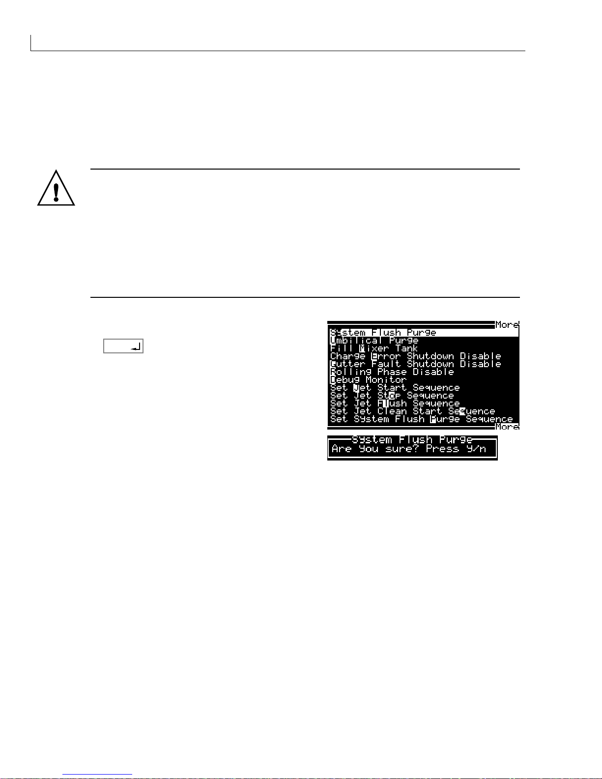
System Flush Purge
.
e
Press
enter
.
f
Press Y to confirm or N to cancel the operation.
The machine starts and the flush pump is actuated. During the actuation of the flush pump, solvent is ejected
from beneath the jet valve.
g
Allow the machine to run for approximately 30 seconds before switching off the mains electrical supply
to the machine to stop the flushing sequence.
h
Tighten the jet valve (V11) screws and dry the printhead.
i
Switch on the mains electrical supply to the machine and perform a clean start and clean stop.
j
Evaluate the clean start/clean stop performance. Repeat the procedure if necessary.
Installation: Setting up Shifts
Issue 2
9
Part No. 306-0430-102
Passwords
Liase with the customer and find out which machine functions they want available to relevant personnel and
which passwords they want to use. Set the Passwords for Levels 1 and 2.
Caution - Degraded Performance
Machine functions that only Willett trained personnel can access are set at Password Level 3 (MASTER
password), these functions must not be given as customer options.
Notes: You must be at Password Level 3 to set Password Levels.
Do not divulge the master password to the customer.
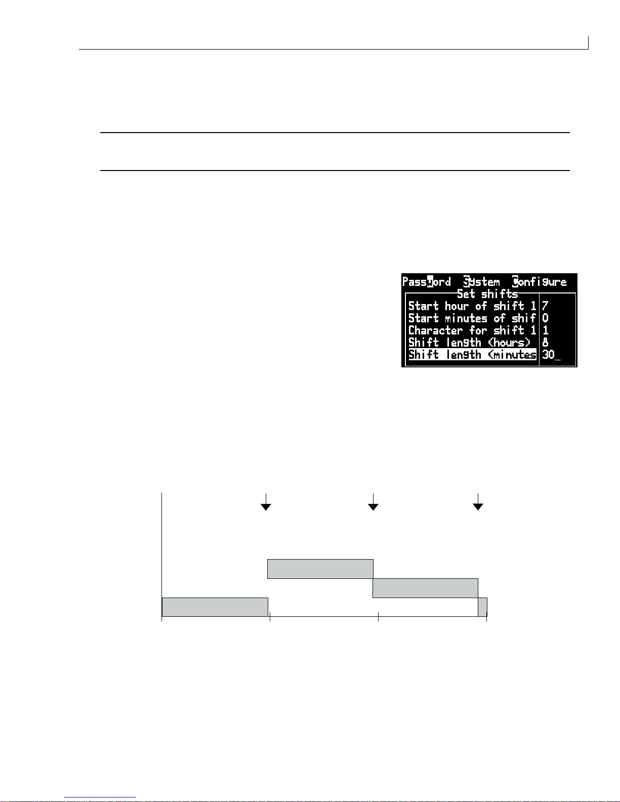
Setting up Shifts
Liase with the customer to confirm shift requirements (if any). The example below show how to set a shift
system where the day is split into three shifts with each shift numbered from 1 and shift 1 starting at 0700.
1
From the
Configure
menu, select
Set Shifts
. The Set Shifts
sub-menu is displayed.
2
Set the shift parameters as follows:
Start hour of shift 1 = 7
Start minutes of shift 1 = 00
Character for shift 1 = 1
Shift length (hours) = 8
Shift length (minutes) = 00
Notes: You must delete the Character for shift 1 using the
backspace
or
del
key before entering a new
value.
Once you enter a start time and length, the other shifts are calculated automatically.
3
Using the Shift criteria defined above, the insertion of a shift at approximately 0330 would provide a shift
number of 2.
07:00
00h
SHIFT 3
SHIFT 1
SHIFT 2
08:00 16:00 23:59
07:00+8=15:00 07:00+8+8=23:00
Figure 5 Shift Setting Diagram
430 Ink Jet Printer Service and Maintenance Manual
10
Issue 2
Part No. 306-0430-102
Production Line Setup
Typical Installation
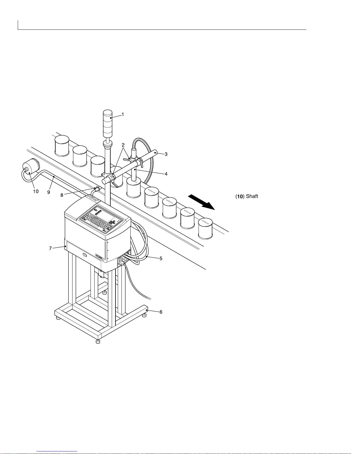
A typical installation is shown in Figure 6, where the printer (7) is mounted on a printer stand (6). The printhead
(4) is configured to print vertically via a clamp (2) and bracket (3) assembly. A lamp stack (1) is fitted to the
printer stand.
(1) Lamp stack
(2) Clamp
(3) Bracket
(4) Printhead
(5) Photocell cable
(6) Printer stand
(7) Printer
(8) Photocell
(9) Shaft encoder cable
1
2
3
4
5
7
9
10
6
8
(10) Shaft encoder
Figure 6 Typical Production Line Installation

Installation: Throw Distance
Issue 2
11
Part No. 306-0430-102
Throw Distance
The optimum throw distance from the printhead to the product is 8 mm.
Shaft Encoder
Internal Source
If no external shaft encoder is to be fitted then set the
Shaft Encoder Source
to
Internal
, via the
Configure
menu. However, if the line speed varies then a shaft encoder
must
be fitted in order to maintain constant
message width.
A Width (Message Parameters) of 1 will provide the fastest print that the printer can achieve in each font using
the Internal Shaft Encoder option. The message width is increased by approximately 3% for each increment.
External Source
If an external shaft encoder is fitted then set the
Shaft Encoder Source
to
External
, via the
Configure
menu.
Figure 6 shows an external shaft encoder (10) connected via a cable (9) to the SHAFT ENCODER connector on
the connector panel.
The printer can be configured to accept two shaft encoder (quadrature) outputs. This allows the printer to
compensate for changes in direction of the production line.
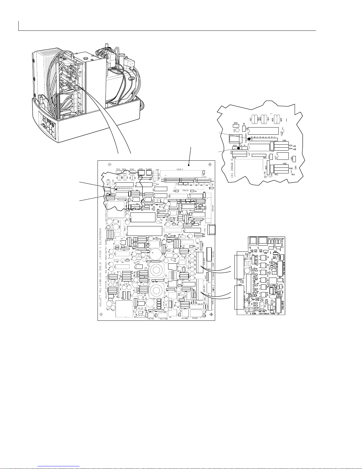
Caution - Electrostatic Sensitive Devices
The printed circuit boards contain static sensitive devices. A suitably grounded, antistatic wrist strap
must be worn when working on or handling printed circuit boards.
If a quadrature shaft encoder is to be used you must do the following:
1
Set jumper JB2 (Figure 7 (2)) to position B.
2
Download the appropriate special software to the printer.
3
Set the Width Value to 1.
4
Disable Print Trigger 2.
Note: Using quadrature shaft encoders to determine changes of direction disables the width function
(ie it must be set to 1). If width control is required, an external divider box must be provided.
430 Ink Jet Printer Service and Maintenance Manual
12
Issue 2
Part No. 306-0430-102
1
3
2
3
2
(1) Input/Output board (2) Sensor 2/Quadrature shaft encoder jumper JB2 (3) Print trigger 1 and 2 jumper JB1
Figure 7 Input/Output Board Product Sensor and Shaft Encoder Jumper Location

Installation: Product Sensors
Issue 2
13
Part No. 306-0430-102
Product Sensors
Figure 6 shows a photocell (8) connected via a cable (5) to PRINT TRIGGER 1 on the connector panel.
The printer can be configured to use two product sensors (PRINT TRIGGER 1 and PRINT TRIGGER 2).
Note: The PRINT TRIGGER 2 option requires the use of non-standard system software.
1
The photocells may be either NPN or PNP devices. Set Jumper JB1 (Figure 7 (3)) on the I/O board to match
the device type. Table 1 lists the settings for jumper JB1.
Table 1 Jumper JB1 Settings
Print trigger Device type Jumper 1 Pins Jumper 2 Pins
1 NPN A 1-2 C 3-4
1 PNP B 2-3 D 4-5
2 NPN F 6-7 H 8-9
2 PNP G 7-8 I 9-10
2
Connect the printer to the mains supply and set the on/off switch to I (on).
3
Select the
Photocell Setup
option from the
Configure
menu.
4
Set the relevant
Photocell level
(s) to
Active high
or
Active low
dependant upon the device type.
(NPN = Active high: PNP = Active low).
 Loading...