

Page 1
POSITIONIT RACK MOUNT CONTROLLER (P/N: 5340101)
OPERATOR’S MANUAL
The Will-Burt Company
169 S. Main Street
Orrville, OH 44667
www.willburt.com
TP-5362301-B, July 2017
© 2017 The Will-Burt Company
Page 2

Page 3
POSITIONIT RACK MOUNT CONTROLLER
TP-5362301-B i
July 2017
Warranty
Will-Burt warrants its PositionIt Rack Mount Controller to be free from defects in
material and workmanship for a period of two (2) years with such time periods
running from the date of shipment by Will-Burt. Will-Burt shall not be responsible
for any damage resulting to or caused by its products by reason of failure to
properly install, maintain or store the product; use of the product in a manner
inconsistent with its design; unauthorized service, alteration of products, neglect,
abuse, accident, or acts of God. This warranty does not extend to any component
parts not manufactured by Will-Burt; provided, however, Will-Burt’s warranty herein
shall not limit any warranties by manufacturers of component parts which extend
to the buyer.
THE FOREGOING WARRANTY IS IN LIEU OF ALL OTHER WARRANTIES, AND
NO REPRESENTATIONS, GUARANTEES OR WARRANTIES, EXPRESS OR
IMPLIED, INCLUDING BUT NOT LIMITED TO, A WARRANTY OF
MERCHANTABILITY, FITNESS FOR A PARTICULAR PURPOSE, OR NONINFRINGEMENT ARE MADE BY WILL-BURT IN CONNECTION WITH THE
MANUFACTURE OR SALE OF ITS PRODUCTS. NO EMPLOYEE,
DISTRIBUTOR, OR REPRESENTATIVE IS AUTHORIZED TO CHANGE THIS
WARRANTY IN ANY WAY OR GRANT ANY OTHER WARRANTY ON BEHALF
OF WILL-BURT.
Claims for defects in material and workmanship shall be made in writing to WillBurt within thirty (30) days of the discovery of defect. Failure to provide notice as
required hereby shall be conclusive evidence that the product was in conformity
with the warranty, and Will-Burt shall be released from any and all liability relating
to the product. Will-Burt may either send a service representative or have the
product returned to its factory at Buyer’s expense for inspection. If judged by WillBurt to be defective in material or workmanship, the product will be replaced or
repaired at the option of Will-Burt, free from all charges except authorized
transportation.
THE REMEDIES OF BUYER SET FORTH HEREIN ARE EXCLUSIVE AND ARE
IN LIEU OF ALL OTHER REMEDIES. THE LIABILITY OF WILL-BURT WHETHER
IN CONTRACT, TORT, UNDER ANY WARRANTY, OR OTHERWISE, SHALL
NOT EXTEND BEYOND ITS OBLIGATION TO REPAIR OR REPLACE, AT ITS
OPTION, ANY PRODUCT OR PART FOUND BY WILL-BURT TO BE DEFECTIVE
IN MATERIAL OR WORKMANSHIP. WILL-BURT SHALL NOT BE LIABLE FOR
COST OF INSTALLATION AND/OR REMOVAL, OR BE RESPONSIBLE FOR
DIRECT, INDIRECT, SPECIAL OR CONSEQUENTIAL DAMAGES OF ANY
NATURE.
Page 4
POSITIONIT RACK MOUNT CONTROLLER
ii TP-5362301-B
July 2017
Document History
Document Numbers
Dates
Remarks
TP-5362301-00
April 21, 2016
Initial Release
TP-5362301-A
June 19, 2017
Updated Table 2-1
TP-5362301-B
July 31, 2017
Added Figure 2-3. Updated to include the
PositionIt PI-35.
Page 5

POSITIONIT RACK MOUNT CONTROLLER
TP-5362301-B iii
July 2017
Table of Contents
Section 1 Introduction .......................................................................................................... 1-1
1.1 Safety Precautions ........................................................................................................................... 1-1
1.2 Manual Organization ........................................................................................................................ 1-1
1.3 Additional Documentation ................................................................................................................ 1-1
1.4 Specifications ................................................................................................................................... 1-2
1.5 What’s in the Box? ........................................................................................................................... 1-2
Section 2 Installation ............................................................................................................ 2-1
2.1 Pre-Installation Check ...................................................................................................................... 2-1
2.2 Physical Installation .......................................................................................................................... 2-2
2.3 System Wiring .................................................................................................................................. 2-3
Section 3 Operation ................................................................................................ .............. 3-1
3.1 Pre-Operation Check ....................................................................................................................... 3-1
3.2 Switching on the System .................................................................................................................. 3-1
3.3 Manual Driving ................................................................................................................................. 3-2
3.4 Stowing and Unstowing the Positioner ............................................................................................ 3-2
3.5 Stow Confirmation ............................................................................................................................ 3-3
3.6 Setting Stow and Unstow Positions ................................................................................................. 3-3
3.7 Setting Pan and Tilt Electronic Limit Stops ...................................................................................... 3-4
Table of Figures
Figure 2-1 PositionIt Rack Mount Controller Dimensions ......................................................................... 2-2
Figure 2-2 PositionIt Rack Mount Controller Connector Pinouts .............................................................. 2-3
Figure 2-3 PositionIt Rack Mount Controller Schematic ........................................................................... 2-4
Figure 3-1 Front Panel of PositionIt Rack Mount Controller ..................................................................... 3-1
Figure 3-2 Front Panel of PositionIt Rack Mount Controller ..................................................................... 3-2
Figure 3-3 Front Panel of PositionIt Rack Mount Controller ..................................................................... 3-2
Figure 3-4 Rear of PositionIt Rack Mount Controller ................................................................................ 3-3
Figure 3-5 Front Panel of PositionIt Rack Mount Controller ..................................................................... 3-3
Figure 3-6 Front Panel of PositionIt Rack Mount Controller ..................................................................... 3-4
Figure 3-7 Front Panel of PositionIt Rack Mount Controller ..................................................................... 3-4
Table of Tables
Table 1-1 PositionIt Rack Mount Controller Specifications ....................................................................... 1-2
Table 2-1 PositionIt Rack Mount Controller Connector Pinouts ............................................................... 2-3
Page 6

POSITIONIT RACK MOUNT CONTROLLER
iv TP-5362301-B
July 2017
Safety Summary
This section describes safety information for the system. These are recommended precautions that
personnel must understand and apply throughout installation, operation, maintenance, and
troubleshooting. Be sure to read and understand the entire manual before performing any procedure
outlined in this manual. Contact the Will-Burt Company with any questions before performing any
procedure outlined in this manual.
Signal Word Definitions
Warnings highlight an essential operating or maintenance procedure, practice, condition, statement,
etc., which, if not strictly observed, could result in injury to, or death of, personnel or long-term health
hazards.
Cautions highlight an essential operating or maintenance procedure, practice, condition, statement,
etc., which, if not strictly observed, could result in damage to, or destruction of, equipment or loss of
mission effectiveness.
Note: Notes highlight an essential operating or maintenance procedure, condition, or statement.
General Safety Instructions
The following are general safety precautions that are not related to any specific procedures. These
are recommended precautions that personnel must understand and apply throughout installation,
operation, maintenance, and troubleshooting. Additional precautions which apply to specific
procedures and steps may be listed with the procedure or step to which they apply.
Electrocution Hazard! Do not touch live wires. Make sure all power has been disconnected prior to
performing installation or maintenance. Make certain that the area is free of overhead power lines
and other unwanted sources of electricity. Do not operate the system during an electrical storm.
Follow OSHA safety regulations when working near energized power lines. Be sure to allow
sufficient clearance on all sides of the mast to allow for side sway. Death or serious injury could
result if proper precautions are not performed.
Shock Hazard! Hazardous voltages are present in this equipment and may also be present in any
associated items. Observe general safety precautions for handling equipment using high voltage.
Always disconnect power before performing repair or test operations. Contact with high voltage will
result in death or serious injury.
Resuscitation! Personnel working with or near high voltages should be familiar with modern
methods of resuscitation. Such information may be obtained from the Bureau of Medicine and
Surgery, United States Navy.
Page 7

POSITIONIT RACK MOUNT CONTROLLER
TP-5362301-B 1-1
July 2017
Section 1 Introduction
Review this manual in its entirety. Contact the Will-Burt Company with any questions before
performing any procedure outlined in this manual.
The PositionIt Rack Mount Controller (P/N: 5340101) is designed to both control and power the
PositionIt positioners. The Rack Mount Controller also offers the ability to integrate other
controllers such as the default remote joystick controller (P/N: 5098901) or a closed contact
controller.
The PositionIt Rack Mount Controller is designed to work with the:
PositionIt PI-150
PositionIt PI-75
PositionIt PI-35
1.1 Safety Precautions
Refer to the Safety Summary for precautions to be observed while operating or servicing this
equipment.
1.2 Manual Organization
This manual is organized into the following sections:
Section 1 Introduction
Section 2 Installation
Section 3 Operation
1.3 Additional Documentation
In addition to this manual (TP-5362301), see the operator’s manual for the appropriate
positioner as follows:
PositionIt PI-150 (P/N: 5061001) and PI-75 (P/N: 5191201) Operator’s Manual (TP-
5129001)
PositionIt PI-35 (P/N: 5467801) Operator’s Manual (TP-5406201)
If necessary, contact The Will-Burt Company to obtain the operator’s manual. During installation
and operation, be sure to follow all appropriate precautions from the operator’s manual.
Page 8

POSITIONIT RACK MOUNT CONTROLLER
1-2 TP-5362301-B
July 2017
1.4 Specifications
Table 1-1 lists specifications for the PositionIt Rack Mount Controller.
Table 1-1 PositionIt Rack Mount Controller Specifications
Specification
Input Voltage
110 – 240 VAC, 50/60 hz
Output Data
RS485 (2 wire) Pelco D, 2400 Baud Rate
Weight
< 2.5 kg (5.5 lb.)
Operational Temperature Range
-20 to 50°C (-4 to 122°F)
1.5 What’s in the Box?
The following items are included in the package:
PositionIt Rack Mount Controller (P/N: 5340101)
Mains Lead – IEC connector to wall socket
Close Contact Connector Mating Half
Positioner Plug Mating Half Connector
Spare Fuse x 2
Rack Mount Fixings Kit
User Manual
Pinout Sheet
QA Documentation
It is important that you retain all these items for future use and reference, even if they are not
used in the initial installation.
Page 9

POSITIONIT RACK MOUNT CONTROLLER
TP-5362301-B 2-1
July 2017
Section 2 Installation
This section describes the installation of the system and provides general procedures that must
be followed to ensure a successful installation. Use care to follow all precautions while installing.
2.1 Pre-Installation Check
Before installing the system, ensure:
That all appropriate precautions from the operator’s manual (Section 1.3) are followed.
That the following warnings are understood and followed:
Safety Instruction – Read Manual! Before attempting any installation, ensure all installers
have fully read and understood this manual.
Safety Instruction – Electrical Hazard! The PositionIt Rack Mount Controller is a mains
powered device and contains dangerous voltages inside.
Safety Instruction – Installation! Ensure the complete system is safe and unable to move
before any installation or maintenance work is carried out on, or around, this system.
Safety Instruction – Qualified Engineers! All electrical and mechanical work must be carried
out by a suitably qualified engineers.
Page 10

POSITIONIT RACK MOUNT CONTROLLER
2-2 TP-5362301-B
July 2017
2.2 Physical Installation
Figure 2-1 describes the physical dimensions of the PositionIt Rack Mount Controller in
millimeters.
Figure 2-1 PositionIt Rack Mount Controller Dimensions
The PositionIt Rack Mount Controller is a 2U profile designed to suit a standard 482.6 (19 inch)
rack mount. Included in the package is a fixings kit which is to be used to install the controller
into a rack mount system.
Page 11

POSITIONIT RACK MOUNT CONTROLLER
TP-5362301-B 2-3
July 2017
2.3 System Wiring
Figure 2-2 and Table 2-1 describe the electrical pinout for the PositionIt Rack Mount Controller.
Figure 2-3 shows the PositionIt Rack Mount Controller schematic.
Figure 2-2 PositionIt Rack Mount Controller Connector Pinouts
Table 2-1 PositionIt Rack Mount Controller Connector Pinouts
1 - Control Plug
3 - Contact Switch Connector
Pin Number
Function
Pin Number
Function
1
Data A
1
Power 24 VDC
2
Data B
2
Low When Stowed
3
12 VDC
3
Power 24 VDC
(To Contacts)
4
0 V
4
Stow 5
Un-Stow
6
Pan CCW
2 - Positioner Plug
7
Pan CW
Pin Number
Function
8
Tilt Up
A
Data A
9
Tilt Down
B
Data B
C
+24 VDC
4 – IEC Power Socket + Fuse Holder
D
0 V
Power 110 VAC – 240 VAC 50-60hz
2 Amp Max Current
Fuse Type - 2 Amp - Quick Blow
Spare fuses provided.
E
Chassis Gnd
1
Pin 1 This End
2 3 4
Page 12

POSITIONIT RACK MOUNT CONTROLLER
2-4 TP-5362301-B
July 2017
Figure 2-3 PositionIt Rack Mount Controller Schematic
Page 13

POSITIONIT RACK MOUNT CONTROLLER
TP-5362301-B 3-1
July 2017
Section 3 Operation
This section describes the operation of the system. Use care to follow all precautions while
operating.
3.1 Pre-Operation Check
Before operating the system, ensure:
That all appropriate precautions from the operator’s manual (Section 1.3) are followed.
Ensure that the following warnings are understood and followed:
Safety Instruction – Installation! Ensure all aspects of the installation have been carried out
correctly and are safe before attempting to operate the system.
Safety Instruction – Operation! Before moving the PositionIt positioner the operator must
first make sure it is safe to do so.
3.2 Switching on the System
The illuminated Power Rocker Switch (Figure 3-1) on the front panel of the Rack Mount controls
both the power for the Rack Mount Controller and also to the positioner.
Once switched on, wait for (10) seconds before attempting any control inputs. This will allow the
system to initialize fully.
Figure 3-1 Front Panel of PositionIt Rack Mount Controller
Power Rocker
Switch
Page 14
POSITIONIT RACK MOUNT CONTROLLER
3-2 TP-5362301-B
July 2017
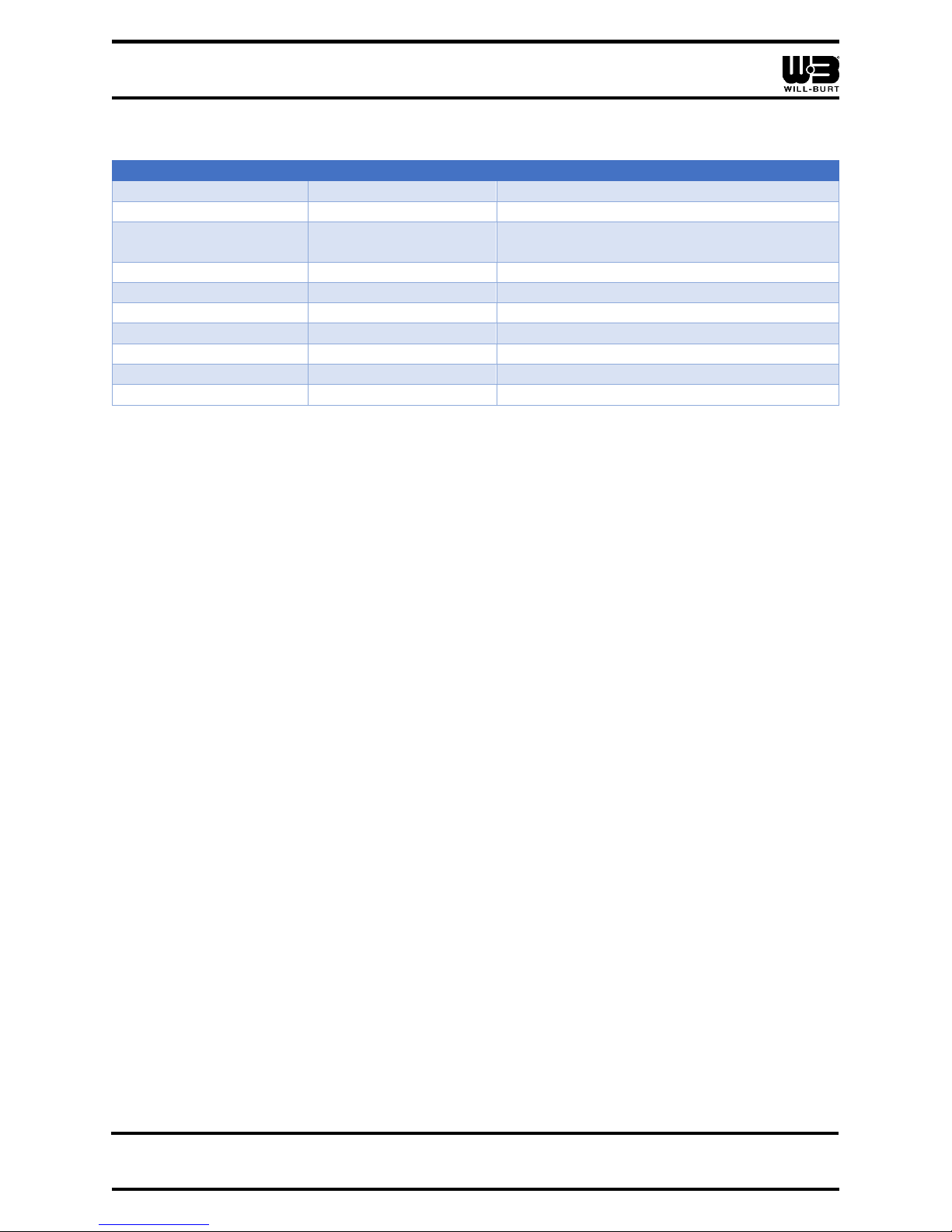
3.3 Manual Driving
The PositionIt system can be manually driven using the (4) arrowed buttons labelled Pan and
Tilt on the front panel (Figure 3-2). These are non-latching push-button controls. To move the
positioner, push and hold the related direction button and release when the desired position is
reached.
The driving speed of the positioner is proportional. When using the Pan and Tilt buttons it will
start slow then ramp up to its maximum over a couple of seconds. Use quick momentary button
presses to achieve accurate small movements.
Figure 3-2 Front Panel of PositionIt Rack Mount Controller
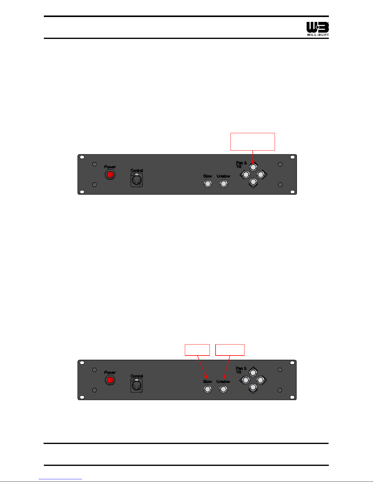
3.4 Stowing and Unstowing the Positioner
To Stow the positioner, simply momentarily press the button labelled “Stow” on the front panel
of the Rack Mount Controller (Figure 3-3). The unit will drive itself to the pre-programmed stow
position.
To unstow the positioner simply momentarily press the button labelled “Unstow” on the front
panel of the Rack Mount Controller (Figure 3-3). The unit will drive itself to the pre-programmed
Unstow position.
If any other control inputs are sent to the positioner before either the Stow or Unstow actions are
complete these will interrupt the process. This will stop the positioner from finishing the stow or
unstow process.
Figure 3-3 Front Panel of PositionIt Rack Mount Controller
Pan and Tilt
Arrows
Stow
Unstow
Page 15

POSITIONIT RACK MOUNT CONTROLLER
TP-5362301-B 3-3
July 2017
3.5 Stow Confirmation
A stow confirmation signal is provided on the rear of the unit through the Phoenix connector
(Figure 3-4). This is provided on Pin 8 as a switched ground.
Figure 3-4 Rear of PositionIt Rack Mount Controller
Once a stow command is sent, the positioner will move to its pre-programmed stow position.
Once this stow position is reached and the positioner has fully stopped this ground on pin 8 will
become active.
Any further input to the positioner will cancel this and the ground will be removed.
Note: This stow confirmation function will not work if the stow command is sent from the
Joystick Control. The unit will stow but no confirmation signal will be shown.
3.6 Setting Stow and Unstow Positions
The Stow and Unstow positions on the positioners can be programmed through the Rack Mount
Controller.
To set the Stow position:
1. Manually drive the positioner into the position required for stowing
2. Press and hold the Pan and Tilt “Left” and “Right” buttons at the same time, then, press
the “Stow” button and hold all three for (3) seconds (Figure 3-5).
Figure 3-5 Front Panel of PositionIt Rack Mount Controller
3. The stow position is now set.
It is advised that the Stow position is tested after being set to ensure it been programmed
correctly.
Stow
Left
Right
Phoenix Connector
Page 16

POSITIONIT RACK MOUNT CONTROLLER
3-4 TP-5362301-B
July 2017
To set the Unstow Position:
1. Manually drive the positioner into the position required for unstowing
2. Press and hold the Pan and Tilt “Left” and “Right” buttons at the same time, then, press
the “Unstow” button and hold all three for (3) seconds (Figure 3-6).
Figure 3-6 Front Panel of PositionIt Rack Mount Controller
3. The unstow position is now set.
It is advised that the Unstow position is tested after being set to ensure it been programmed
correctly.
3.7 Setting Pan and Tilt Electronic Limit Stops
The positioner uses electronic limit stops. The positioner does not have mechanical hard stops.
The positioner comes from the factory with electronic limit stops set to the maximum
recommended pan and tilt. The limit stops can be adjusted through the controller, but it is not
possible to remove the limit stops completely.
To set the electronic limit stops:
1. Connect the default joystick controller (P/N: 5098901) to the control connector
(Figure 3-7).
Figure 3-7 Front Panel of PositionIt Rack Mount Controller
2. Set the electronic limit stops according to the operator’s manual (Section 1.3).
3. Remove the default joystick controller.
4. Verify the electronic limit stops.
Unstow
Left
Right
Control Connector
 Loading...