

Page 1

Night Scan Chief
NIGHT SCAN CHIEF
INSTALLATION, OPERATION & MAINTENANCE MANUAL
The Will-Burt Company
169 S. Main Street
Orrville, OH 44667
www.willburt.com
Revision 1 i
Revision 1, December 2007
Page 2

Page 3

Night Scan Chief
WARRANTY
The Manufacturer warrants its products to be free from defects in material and
workmanship for a period of one year from the date of shipment from the factory.
The Manufacturer shall not be responsible for any damage resulting to or caused by
its products by reason of improper installation, improper storage, unauthorized
service, alteration of products, neglect or abuse, or use of the product in a manner
inconsistent with its design, accident, acts of God, or failure to properly maintain this
product. This warranty does not extend to any component parts not manufactured by
Manufacturer, however, Manufacturer's warranty herein shall not limit any warranties
made by manufacturers of component parts which may extend to Buyer.
THE FOREGOING WARRANTY IS IN LIEU OF ALL OTHER WARRANTIES, AND
NO REPRESENTATIONS, GUARANTEES OR WARRANTIES, EXPRESS OR
IMPLIED, (INCLUDING, BUT NOT LIMITED, TO A WARRANTY OF
MERCHANTABILITY OR FITNESS FOR A PARTICULAR PURPOSE) ARE MADE
BY MANUFACTURER IN CONNECTION WITH THE MANUFACTURE OR SALE OF
ITS PRODUCTS. NO EMPLOYEE, DISTRIBUTOR, OR REPRESENTATIVE IS
AUTHORIZED TO CHANGE THIS WARRANTY IN ANY WAY OR GRANT ANY
OTHER WARRANTY ON BEHALF OF MANUFACTURER.
Claims for defects in material and workmanship shall be made in writing to
Manufacturer within thirty (30) days of the discovery of defect. Failure to provide
notice as required hereby shall be conclusive evidence that the product was in
conformity with the warranty, and the Manufacturer shall be released from any and all
liability relating to the product. Manufacturer may either send a service
representative or have the product returned to its factory at Buyer's expense for
inspection. If judged by Manufacturer to be defective in material or workmanship, the
product will be replaced or repaired at the option of Manufacturer, free from all
charges except authorized transportation.
THE REMEDIES OF BUYER SET FORTH HEREIN ARE EXCLUSIVE AND ARE IN
LIEU OF ALL OTHER REMEDIES. THE LIABILITY OF MANUFACTURER
WHETHER IN CONTRACT, TORT, UNDER ANY WARRANTY, OR OTHERWISE,
SHALL NOT EXTEND BEYOND ITS OBLIGATION TO REPAIR OR REPLACE, AT
ITS OPTION, ANY PRODUCT OR PART FOUND BY MANUFACTURER TO BE
DEFECTIVE IN MATERIAL OR WORKMANSHIP. MANUFACTURER SHALL NOT
BE LIABLE FOR COST OF INSTALLATION AND/OR REMOVAL, OR BE
RESPONSIBLE FOR DIRECT, INDIRECT, SPECIAL OR CONSEQUENTIAL
DAMAGES OF ANY NATURE.
Revision 1 i
Page 4

Page 5

Night Scan Chief
TABLE OF CONTENTS
0. SAFETY SUMMARY I
1. INTRODUCTION 1-1
1.1 Safety Precautions................................................................................................................................1-1
1.2 Introduction............................................................................................................................................1-1
1.3 Description.............................................................................................................................................1-1
1.4 Reference Data.....................................................................................................................................1-2
1.5 Technical Information............................................................................................................................1-2
INSTALLATION 2-1
2.
2.1 Introduction............................................................................................................................................2-1
2.2 Tools and Materials Required for Installation........................................................................................2-1
2.3 Unpacking..............................................................................................................................................2-2
2.4 Attaching to vehicle...............................................................................................................................2-2
2.5 Connecting the Push/Pull Switch (Junction Box)..................................................................................2-4
2.6 Connecting the Remote Control(s)........................................................................................................2-4
2.7 Connecting the Interlock Contact (optional)..........................................................................................2-5
2.8 Connecting Interlock Input Contacts (optional).....................................................................................2-5
2.9 Installing the Warning Light...................................................................................................................2-6
2.10 MULTIPLEX SYSTEMS OPERATING AT 24 VOLTS........................................................................2-6
2.11 Pre-operational Check.........................................................................................................................2-6
3. OPERATING INSTRUCTIONS 3-1
3.1 Theory of Operation – Mechanical........................................................................................................3-2
3.2 Theory of Operation – Electrical............................................................................................................3-3
3.3 Push/Pull Switch – NFPA INSTALLATIONS.........................................................................................3-3
3.4 Push/Pull Switch – non-NFPA INSTALLATIONS..................................................................................3-4
3.5 Remote Controls (Hand held)................................................................................................................3-4
3.6 Raising the Mast....................................................................................................................................3-5
3.7 Aiming the Remote Control Positioner..................................................................................................3-5
3.8 Stowing the Mast...................................................................................................................................3-5
3.9 Emergency Stow (Loss of Power):........................................................................................................3-6
MAINTENANCE AND SERVICE INSTRUCTIONS 4-1
4.
4.1 Introduction............................................................................................................................................4-1
4.2 Scheduled Maintenance........................................................................................................................4-1
4.3 Adjustments...........................................................................................................................................4-2
4.4 System Schematics...............................................................................................................................4-7
4.5 Troubleshooting Electrical...................................................................................................................4-10
4.6 Troubleshooting Mechanical ...............................................................................................................4-19
5.
PARTS LIST 5-1
5.1 Part Lists................................................................................................................................................5-1
6. REVISIONS 6-1
Revision 1 i
Page 6

Night Scan Chief
7. SOFTWARE REVISIONS 7-1
7.1 Introduction.........................................................................................................................................7-1
8. APPENDICES 8-2
LIST OF ILLUSTRATIONS
Figure 1-1 Night Scan Chief Base and Remote Control Positioner.............................................................. 1-1
Figure 1-2 Mast Loads..................................................................................................................................1-1
Figure 2-1 Lifting Point..................................................................................................................................2-2
Figure 2-2 Night Scan Base Mounting Hole Locations................................................................................. 2-3
Figure 2-3 Standard Junction Box ................................................................................................................ 2-3
Figure 2-4 Junction Mounting Hole Locations...............................................................................................2-4
Figure 2-5 Hand Held Receptacle Pins......................................................................................................... 2-5
Figure 2-6 Example of Warning Light Installation......................................................................................... 2-6
Figure 3-1 Actuator and Proximity Sensors..................................................................................................3-2
Figure 3-2 Photo Interrupter and Flag...........................................................................................................3-3
Figure 3-3 Cover and Screw Removal for Manual Stow (Night Scan Chief only) ........................................ 3-7
Figure 4-1 Proximity Switch Adjustment .......................................................................................................4-3
Figure 4-2 LED Location and Function.........................................................................................................4-3
Figure 4-3 Flag Settings................................................................................................................................4-5
Figure 4-4 DIP switch location: Chief base board.........................................................................................4-6
Figure 4-5 DIP switch location: Chief RCP board.........................................................................................4-6
Figure 4-6 NFPA Handheld Remote Wiring..................................................................................................4-7
Figure 4-7 Non-NFPA Hand Held Remote Wiring ........................................................................................4-7
Figure 4-8 Night Scan Chief Base Wiring.....................................................................................................4-8
Figure 4-9 Night Scan Chief Remote Control Positioner (RCP) Schematic.................................................4-9
Figure 5-1 Exploded View - Base Left Side..................................................................................................5-2
Figure 5-2 Base Right Side...........................................................................................................................5-3
Figure 5-3 Exploded View – Mast Pivot Assembly .......................................................................................5-3
Figure 5-4 Exploded View - Remote Control Positioner (RCP)....................................................................5-5
Table 1-1. Reference Data Night Scan Chief..................................................................................................1-2
Table 2-1. Tools and Materials Required for Installation................................................................................2-1
Table 2-2. Handheld Remote Control Connector Pin-out............................................................................... 2-5
Table 4-1. List of Base Board Faults............................................................................................................. 4-10
Table 4-2. List of Remote Control Positioner Board Faults .......................................................................... 4-14
Table 4-3. List of Remote Control Board Faults............................................................................................4-17
Table 4-4. List of Warning Codes .................................................................................................................4-18
Table 4-5. Mechanical Troubleshooting........................................................................................................4-19
Table 5-1. Night Scan Chief Base Assembly Parts List..................................................................................5-1
Table 5-2. Remote Control Positioner Assembly Parts List............................................................................5-4
Table 7-1. Software Revision Log...................................................................................................................7-1
Revision 1 ii
LIST OF TABLES
Page 7

Night Scan Chief
SAFETY SUMMARY
SIGNAL WORD DEFINITION
Per the ANSI Z535.4 standard, the following signal words and definitions are used to indicate hazardous
situations:
DANGER indicates an imminently hazardous situation that, if not avoided, will result in death or serious injury.
WARNING indicates a potentially hazardous situation that, if not avoided, could result in death or serious
injury.
CAUTION indicates a potentially hazardous situation that, if not avoided, may result in minor or moderate
injury. It is also used to alert against unsafe practices.
GENERAL SAFETY PRECAUTIONS
The following are general safety precautions that are not related to any specific procedures and therefore do
not appear elsewhere in this publication. These are recomm ended precautions that personnel must
understand and apply during many phases of operation and maintenance.
Electrocution Hazard! Contact with high voltage will result in death or serious injury. Observe general
safety precautions for handling equipment using high voltage. Do not locate or operate mast near electrical
lines, cables or other unwanted sources of electricity. Do not operate mast in lightning. Be certain electrical
cables are undamaged and properly terminated. Always disconnect power before performing service, repair
or test operations.
Safety Instruction - Read Manual! Failure to follow operating instructions could result in death or serio us
injury. Read and understand the operator’s manual before using the mast.
Tip Over Hazard! Mast tip over could result in death or serious injury. Do not operate in high winds.
Operate on level ground only. Stand clear of mast and mast payload during operation. Be certain mast is
level and secure before and during installation, operation and maintenance.
Safety Instruction - Trained Personnel Only! Death or serious injury could result if proper inspection,
installation, operation and maintenance procedures are not observed. Installation, operation and
maintenance to be performed by trained and authorized personnel only. Proper eye protection should be
worn when servicing the mast.
Health and Safety Hazard! Solvent used to clean parts is potentially dangerous. Avoid inhalation of fumes
and also prolonged contact to skin.
Safety Instruction-Do not look at lights! Do not look directly into lights when they are illuminated.
Temporary impairment or permanent vision damage could occur.
Revision 1 i
Page 8

Night Scan Chief
SPECIFIC SAFETY PRECAUTIONS
The following are safety precautions that are related to specific procedures and therefore appear elsewhere in
this publication for emphasis. These are recommended precautions that personnel must understand and
apply during specific phases of installation, operation and maintenance.
Safety Instruction-Operation! For outdoor use only. Do not use in areas that have been classified as
hazardous as defined in Article 500 of the National Electric Code.
Crush Hazard! Death or serious injury could result if mast fails suddenly. Do not stand directly beneath the
mast or its payload. Be certain payload is properly installed and secured.
Burst Hazard! Over pressurizing mast will trip safety valve and could result in death or se rious injury. Do not
exceed maximum operating pressure of 20 psi (138 kPa) for Standard Duty masts. Keep personnel clear of
safety valve exhaust direction.
Fire Hazard! Cleaning solvent, used for maintenance, is flammable and can be explosive resulting in death
or serious injury. Do not smoke. Use cleaning solvent in a well-ventilated area. Keep cleaning solvent away
from ignition sources. Always store cleaning solvent in the proper marked container.
Relocation Hazard! Relocating the mast during operation or after extension could result in death or serious
injury. Do not relocate the mast during operation or while extended. This applies especially to masts
mounted to vehicles. Operate the mast only if the vehicle is stationary and the vehicle engine is off.
Mast Extension Hazard! Extending mast into obstructions could result in death or serious injury and could
render the mast inoperable and partially extended. Before applying power and operating the mast, be certain
there is sufficient clearance above and to all sides of the expected location of the fully extended mast and
payload. Keep all persons clear of mast and mast extension. Do not lean directly over the mast.
Mounting Structure Hazard! Mounting mast into a structure unable to resist the forces generated from
customer-specific loading scenario could result in death or serio us injury and could damage the mast. Before
operation, be certain mounting structure is capable of resisting forces generate d from all loa ding and
environmental conditions, including, but not limited to, mast size and weight, payload size and weight, sail
size, wind speed, guy line arrangement, support bracket or roof line location and base plate assembly.
Electrocution Hazard! Do not touch live wires. Death or serious injury could result.
Safety Instruction – Operation! Make sure all power has been disconn ected prior performing maintenance.
Revision 1 ii
Page 9
Night Scan Chief
Safety Instruction -Trained Personnel Only! Only trained and qualified personnel should perform
installation, adjustments, and servicing. Only a properly trained and qualified certified electrician should
perform electric installations and service.
When relamping an installed fixture, make sure all power to fixture is off and that the fixture is cool
Safety Instruction – Operation! At all times prior to mast operation, insure that:
1.) The mast area is free of personnel and mechanical obstruction;
2.) All electrical cables are undamaged and properly terminated;
3.) The operator must have full view of the mast during use;
4.) Any transit tie-downs on the payload have been removed;
5.) The vehicle is not moving;
6.) The area above the mast is free of mechanical obstructions.
Safety Instruction-Operation! Lamps are extremely hot and should not come into contact with people or
combustible and/or explosive materials. Do not operate if breakage occurs or unit is knocked over.
Entanglement Hazard! Tangled cables can cause equipment damage. Ensure control cables are not
tangled and are free to pay out as mast is extended.
Safety Instruction – Installation! At all times while using pipe and hose during installation, recognize that:
1.) Pipe and hose should be routed, mounted and restrained to protect from damage;
2.) Do not use second hand piping for installation;
3.) Do not bend air pipe and hose at a radius less than specified by the manufacturer;
4.) Pipes should be marked to avoid hazards from incorrect connection;
5.) The exhaust should be fitted with a silencer and be directed away from personnel;
6.) When routing piping, install in such a way as to minimize torsion on the joints;
7.) Mounting air pipe and hose shall be accomplished only by the use of tools to prevent readily
disconnecting air pipe and hose from mast.
Safety Instruction – Operation! Do not operate the Chief vertical RCP during an electrical storm.
Lifting Hazard! Manually lifting over 55 lb (25kg) is prohibited. In the UK, all lifting equipment must be
thoroughly examined annually by a competent person according to the Lifting Operations and Lift Equipment
Regulations 1998. Equivalent regulations exist in other EU states.
Safety Instruction – Operation! All operators must read the Operation section of this manu al and be
Revision 1 iii
properly trained.
Page 10

Page 11
Night Scan Chief
CHAPTER 1
INTRODUCTION
1.1 SAFETY PRECAUTIONS
Refer to the Safety Summary for precautions to be observed while operating or servicing this equipment.
1.2 INTRODUCTION
This manual covers the installation, operation, troubleshooting and maintenance instructions for the Night
Scan Chief. The manual should be reviewed in its entirety. Contact the Will-Burt factory with any questions
before performing any procedures outlined in this manual.
1.3 DESCRIPTION
The Night Scan Chief is a transportable lighting system consisting of a directionally adjustable group of lights
attached to a self-erecting, extensible mast. Air pressure required to extend the mast is provided by a
compressor unit mounted within the Night Scan Chief. The unit is designed for installation on any vehicle for
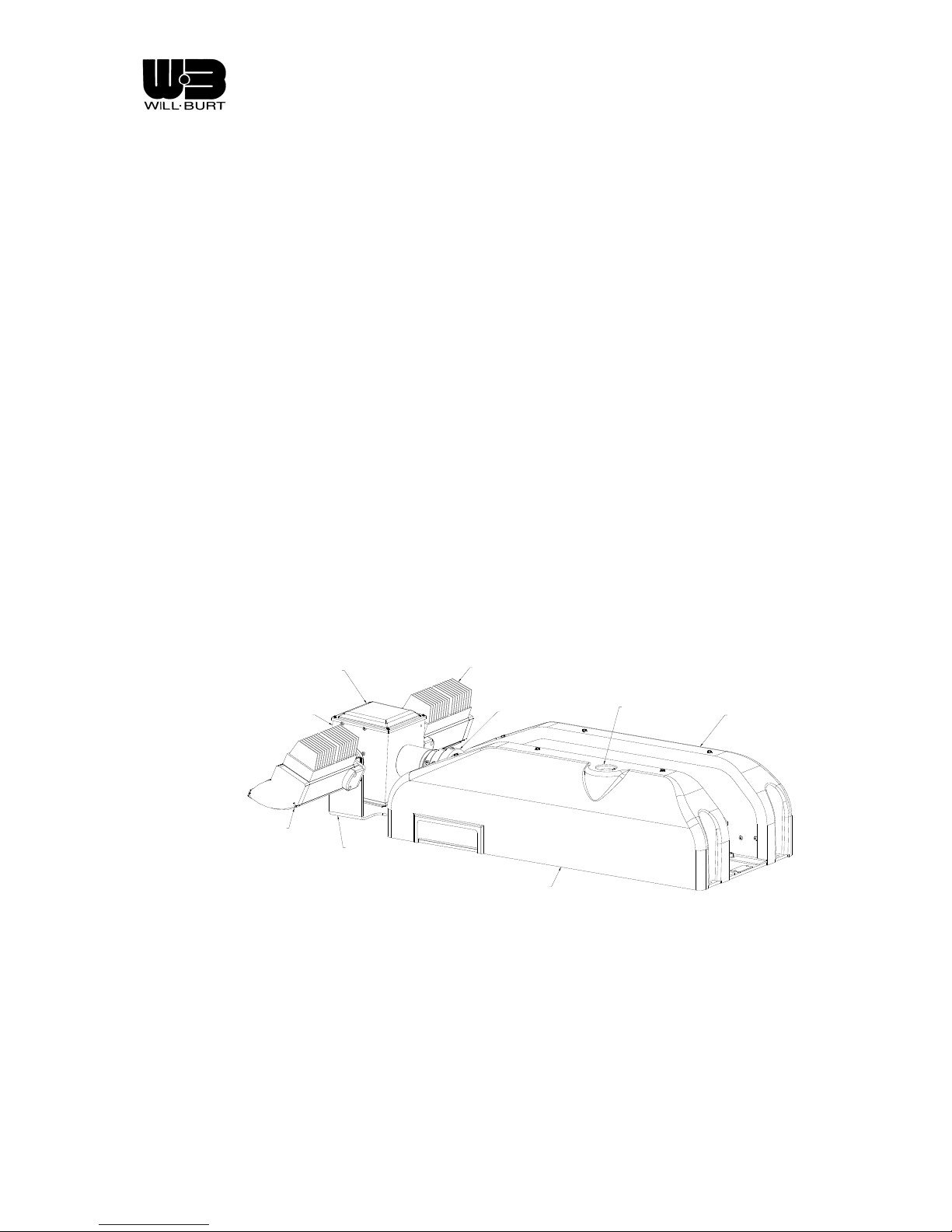
the purpose of providing on the scene temporary lighting. Refer to Figure 1-1 for identification of the major
components of the Night Scan Chief unit.
RIGHT SIDE
LIGHT
MAST
LEFT COVER
BASE
BASE
LOOK-UP LIGHT
RCP HOUSING
LEFT SIDE
LIGHT
RCP COVER
RCP SADDLE
ASSEMBLY
Figure 1-1 Night Scan Chief Base and Remote Control Positioner
BASE
RIGHT COVER
Revision 1 1-1
Page 12

Night Scan Chief
1.4 REFERENCE DATA
The reference data for the Chief given in Table 1-1 is not inclusive of all models. Please refer to product
literature or www.willburt.com
for additional information including length, width and height information.
Table 1-1. Reference Data Night Scan Chief
Model No. 140DC 300DC 1800 3000P 5400 6000
NS6 Stowed Height 10 in 10 in 10 in 10 in 10 in 10 in
NS7.5 Stowed Height 10 in 10 in 10 in 10 in 10 in 10 in
NS6 Ext. Height 6ft. 6ft. 6ft. 6ft. 6ft. 6ft.
NS7.5 Ext. Height 7ft-6in 7ft-6in 7ft-6in 7ft-6in 7ft-6in 7ft-6in
Total Unit Weight** 100 lb. 100 lb. 100 lb. 110 lb. 120 lb. 130 lb.
Tube Diameter Range 3.5 to 2.5in 3.5 to 2.5in 3.5 to 2.5in 3.5 to 2.5in 3.5 to 2.5in 3.5 to 2.5in
No. of Mast Sections 3 3 3 3 3 3
Mast Air Volume
(NS7.5)
Max. Operating
Air Pressure
Required DC Electrical
Power Supply
Required Electrical
Supply for Lights
0.26 cu. ft. 0.26 cu. ft. 0.26 cu. ft. 0.26 cu. ft. 0.26 cu. ft. 0.26 cu. ft.
20 psi 20 psi 20 psi 20 psi 20 psi 20 psi
12V/20 amp
24V/10 amp
12V/12 amp
24V/6 amp
12V/20 amp
24V/10 amp
12V/25 amp
24V/13 amp
12V/20 amp
24V/10 amp
220V/10
amp
12V/20 amp
24V/10 amp
220V/15
amp
12V/20 amp
24V/10 amp
220V/25
amp
12V/20 amp
24V/10 amp
220V/30
amp
*Maximum dimension is the largest dimension on all specified models.
**Weight given is approximate for 7.5-foot models
1.5 TECHNICAL INFORMATION
Power Requirements
The DC power for the Chief is supplied through direct connection to the base circuit board. The DC
power is internally protected with a 20 amp auto-resetting circuit breaker. The Chief will operate from
either 12 or 24 volt DC power with no customer changes necessary. The electronic system has built in
reverse polarity protection. For optimum performance, a minimum of 11 volts is required at the Chief
base. Long runs of cable can introduce power loss For long runs, it may be necessary to add an
intermediate junction box in the DC cable so that DC power can be applied closer to the Chief.
Revision 1 1-2
Page 13
Night Scan Chief
Mast Loads
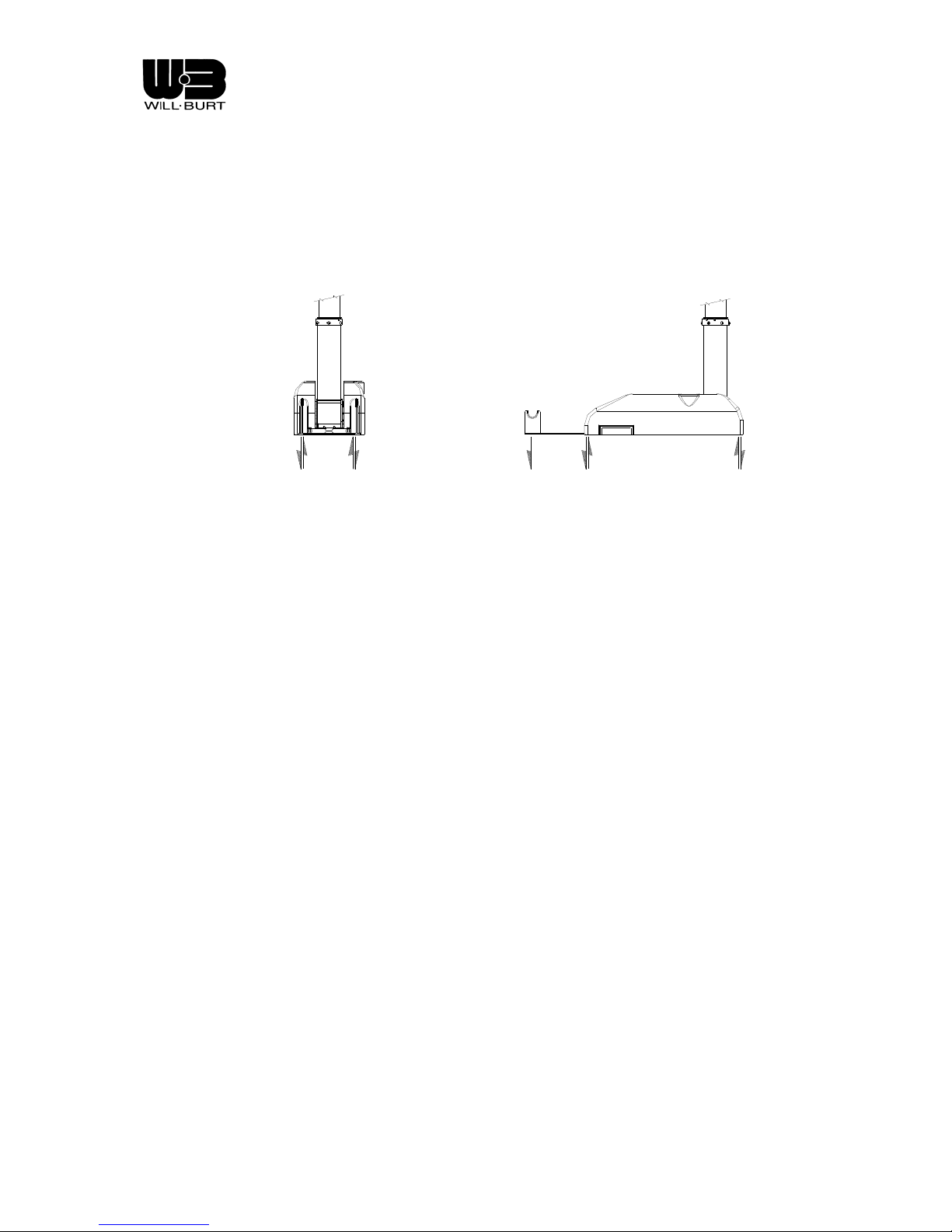
It is important that the mast be securely mounted to a sturdy platform, which will not overturn during
operational loading of the mast. Figure 1-2 provides loading information for the mast, which can be
expected during operation. All values given are in lbs.
35# 200# 200#575# 575#
Figure 1-2 Mast Loads
Revision 1 1-1
Page 14

Page 15
Night Scan Chief
CHAPTER 2
INSTALLATION
Safety Instruction -Trained Personnel Only! Only trained and qualified personnel should perform
installation, adjustments, and servicing. Only a properly trained and qualified certified electrician should
perform electric installations and service.
Safety Instruction -Trained Personnel Only! Only trained and qualified personnel should perform
installation, adjustments, and servicing. Only a properly trained and qualified certified electrician should
perform electric installations and service.
Lifting Hazard! Manually lifting over 55 lb (25kg) is prohibited. In the UK, all lifting equipment must be
thoroughly examined annually by a competent person according to the Lifting Operations and Lift Equipment
Regulations 1998. Equivalent regulations exist in other EU states.
2.1 INTRODUCTION
The Chief has been designed to provide for ease of installation. This section of the manual provides the
procedures that must be followed to insure a successful installation. Be sure to read and understan d the
entire installation procedure before you begin.
2.2 TOOLS AND MATERIALS REQUIRED FOR INSTALLATION
Table 2-1 provides a list of tools and materials required to install and test the Night Scan Chief.
Wrenches Crimping tool or Solder set
Screwdrivers Wire cutter/stripper
½ inch or M12 Mounting Hardware (6 each) Multimeter (to verify power is turned OFF)
Torque wrench Clean Shop Rags
Drill
Hoist (minimum 250 lb capacity)
Table 2-1. Tools and Materials Required for Installation
Revision 1 2-1
Page 16
Night Scan Chief
2.3 UNPACKING
Unpack the Night Scan Chief as follows:
1. Carefully open and remove all parts from shipping container.
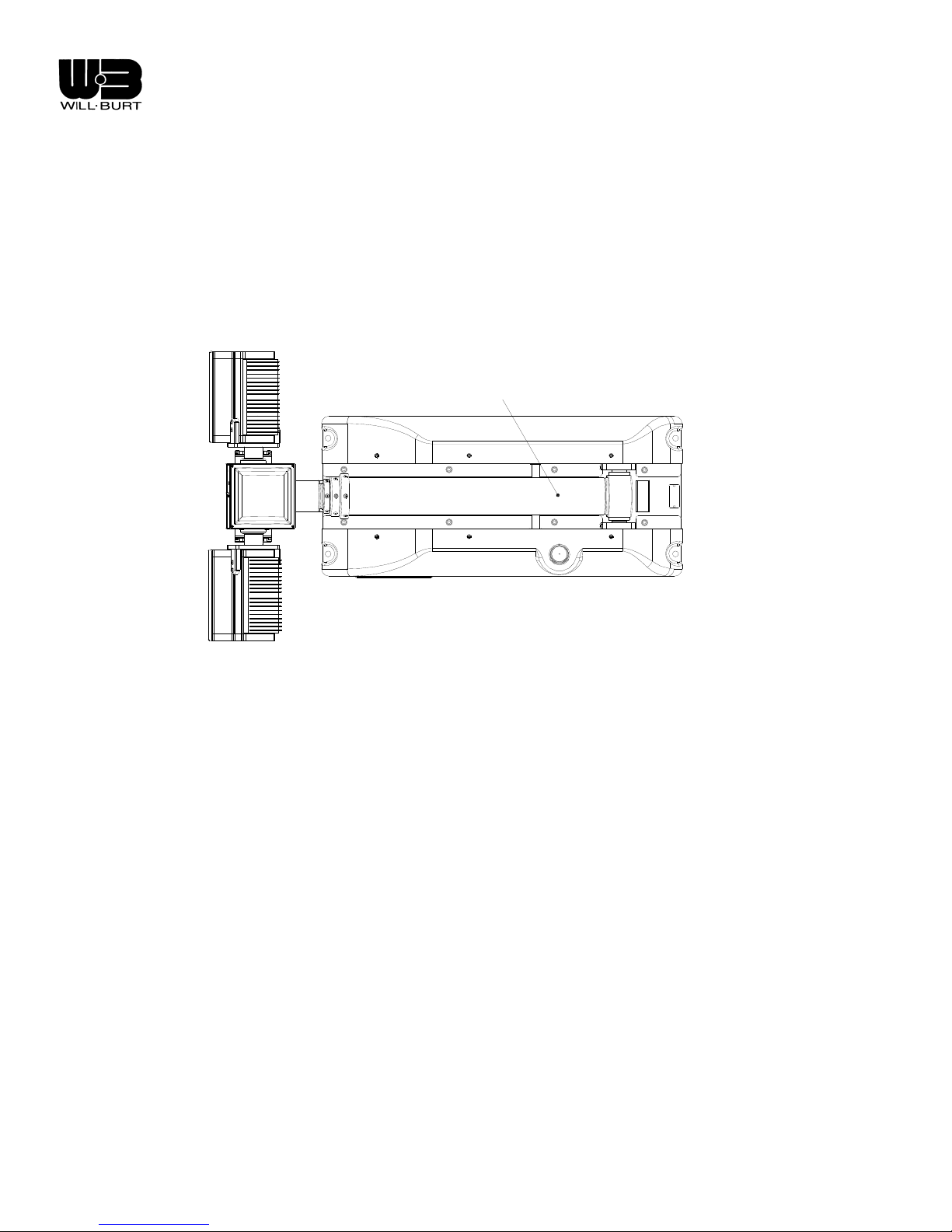
o Lift the unit from the shipping container by the base tube (see Figure 2-1).
o Do not lift the Night Scan by the lights or RCP.
2. Inspect for any shipping damage. If damage has occurre d, notify carrier.
3. Be sure that all components are include d and that the requi red tools are readily available.
LIFTING POINT
Figure 2-1 Lifting Point
2.4 ATTACHING TO VEHICLE
If the Night Scan Chief is to be mounted in a well, be certain that adequate drainage is provided. A minimum
of (4) drain holes (one per corner) at least one inch in diameter is recommended . While the unit has been
designed to withstand adverse environmental conditions, it cannot be submerged.
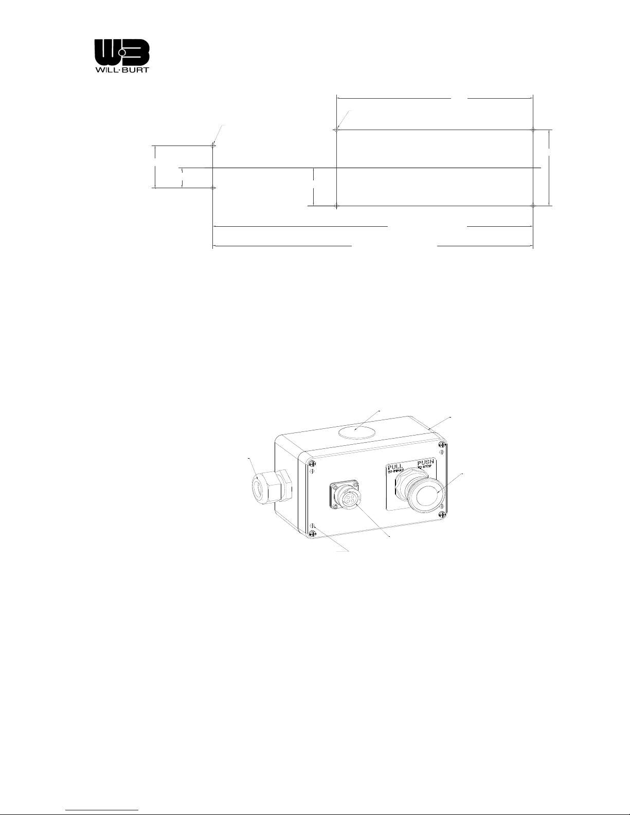
The mounting holes provided on the unit are 9/16 inches in diameter. There are four holes in t he base plate
and two holes in the RCP saddle. Studs or bolts (not provided) shall be located on the vehicle in accordance
with Figure 2-2. It is important that the surface be flat such that the saddle and base plate are in the same
plane. The areas to which the unit is mounted must be reinforced to withstand loading as shown in Figure
1-2. Attach and torque all hardware as appropriate for its material and size. It may be advantageous to
attach the four (4) mounting bolts in the base plate, complete the wiring as outlined in the following sections
and raise the unit before attaching the saddle bolts. Be certain that the saddle bolts are located in
accordance with Figure 2-2 and that the saddle is centered with respect to the RCP. Adjust the location if
necessary.
Revision 1 2-2
Page 17
Night Scan Chief
33.0
SADDLE MOUNTING
HOLES (
n.56" SEE NOTE)
BASE MOUNTING
HOLES (
n.56" SEE NOTE)
4.8
2.4
5.5
40 1/8" (6FT. MAST)
46 1/8" (7.5FT. MAST)
11.0
Figure 2-2 Night Scan Base Mounting Hole Locations
Junction Box Installation
The junction box serves as an interface between the Hand Held Remote Control and the Night Scan
Base. It is not used in installations where only the Panel Mount Remote Control is used. The junction
box is not rated for installation in wet locations. The installer must take necessary precautions to seal the
lid and the knockouts if installation in a wet location is unavoidable. The junction box also serves as a
location to which DC power is routed by the installer for the unit. It may be flush or surface mounted.
Hardware for mounting is not supplied.
KNOCK-
OUT
JUNCTION BOX
ENCLOSURE
COR D GRIP F OR
DC \ CONTROL CABLE
TO NIGHT SCAN
HOLES PROVIDED
FOR OPTIONAL
FLUSH MOUNTING
HHRC CONNECTOR
PUSH
PULL
SWITCH
Figure 2-3 Standard Junction Box
Flush Mounting
For a flush mount installation, four #8 screws, nuts and lock washers must be provided by the installer.
The screw length should be 3 ½ inches plus the panel thickness. Remove the junction box cover and
make the necessary cable connections (see schematics in section 4.4). Place the jun ction box behind
the panel and guide the screws through the panel, junction box cover and junction box. Secure on back
side using lock washers and nuts.
Revision 1 2-3
Page 18
Night Scan Chief
Surface mounting
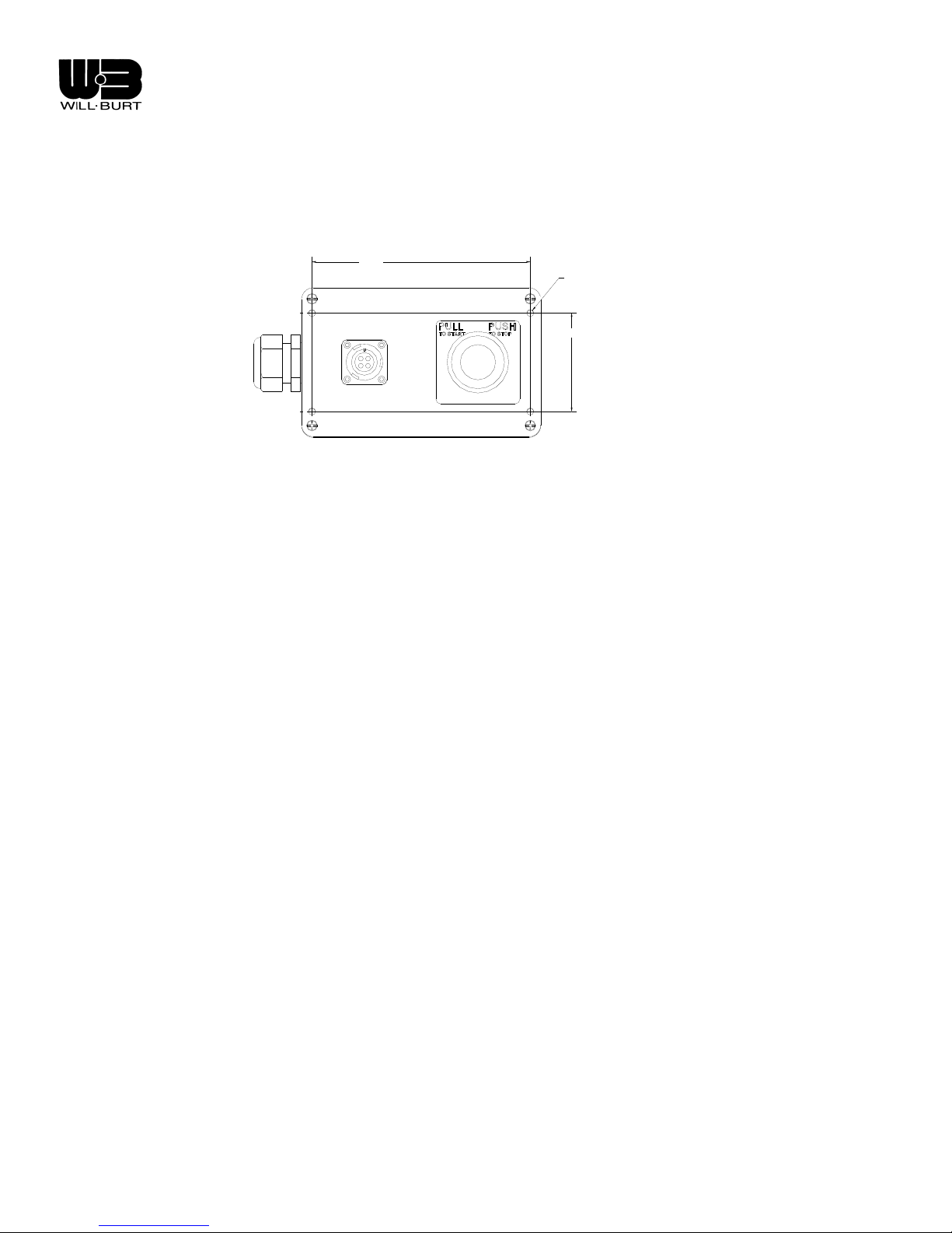
For a surface mount installation, four #8 screws, nuts and lock washers mu st be provide d by the install er.
The screw length should be ¾ inch plus the panel thickness. Remove the junction box cover and mou nt
unit through the counter bored holes in the junction box. Secure on the back side using lo ck washers and
nuts. Make the necessary cable connections (see schematics in section 4.4) and replace cover.
5.75"
MOUNTING HOLES
" SEE NOTE)
(Ø.19
2.60"
Figure 2-4 Junction Mounting Hole Locations
2.5 CONNECTING THE PUSH/PULL SWITCH (JUNCTION BOX)
While a two switch implementation of this circuit can be realized, the use of a Push/Pull switch is highly
preferred. One switch available for non-NFPA installations is a Square-D 9001K R9RH13. For NFPA
compliant installations, Square-D part number 9001SKR8RH25 should be u sed. Other ma nufacturers of
Industrial Control Pilot Devices should have equivalent switches. This switch is available as part of a prewired kit (part # 913316 for NFPA or part #4204201 for non-NFPA installations) from Will-Burt. Refer to the
schematics in section 4.4 for wiring detail.
2.6 CONNECTING THE REMOTE CONTROL(S)
Hand Held Remote Control (HHRC)
In the event that the accessory kit (part # 913316 or 4204201) is not used, a suitable connector mu st be
supplied by the customer to mate with the connector of the handheld remote control (HH RC ). The co nnector
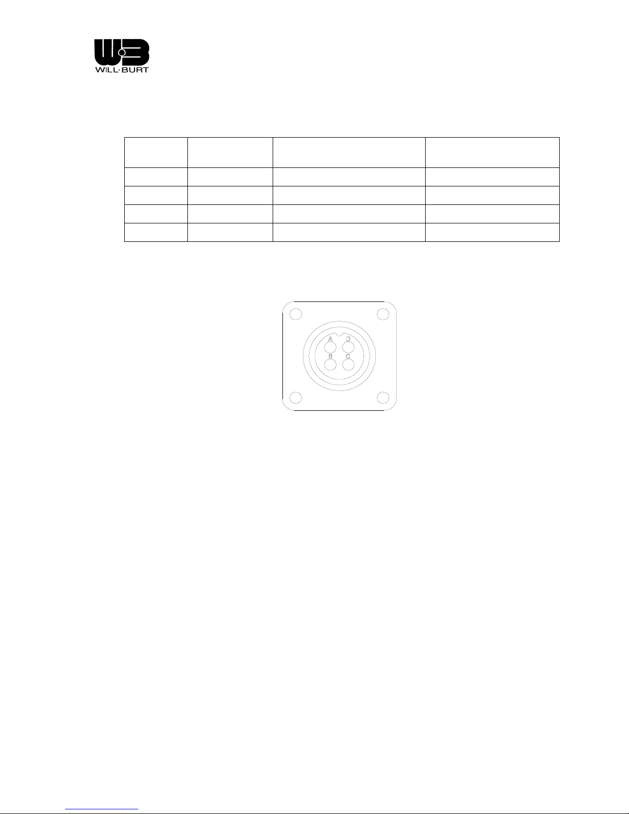
on the HHRC is an ITT Cannon CA3106E14S-2P-B-F80-A232. Please refer to Table 2-2 and Figure 4-7 for
wiring schematic.
Pin B of the HHRC should connect to pin A of the DC Power/input connector. Pin C of the HHRC should
connect to pin B of the DC Power/input connector. Pin A of the HHRC should connect to pin C of the DC
Power/input connector. Pin D of the HHRC should connect to pin D of the DC Power/input connector.
Revision 1 2-4
Page 19
Night Scan Chief
Table 2-2. Handheld Remote Control Connector Pin-out
HHRC Pin Pin Function
To Pin of DC Power
Connector
Recommended Wire Ga.
A + Signal C 20
B + Power A 20
C - Power B 20
D - Signal D 20
Figure 2-5 Hand Held Receptacle Pins
2.7 CONNECTING THE INTERLOCK CONTACT (OPTIONAL)
The Chief provides an interlock relay contact output to enhance integration into vehicle safety circuitry. This
relay output is from a bi-stable (latching) relay whose contacts close when the unit has completely stowed.
This type of scenario gives the best failsafe condition in the event of a broken wire. Its state is not affected by
whether or not there is power to the mast. This isolated contact is capable of carrying up to 2 amperes and is
available on pins J4-8 and 9. Please refer to the schematics in section 4.4. Its usage is at the discretio n of the
integrator. It can be used in conjunction with a customer-supplied relay to drive a flashing warning light. (refer
to Figure 2-6)
2.8 CONNECTING INTERLOCK INPUT CONTACTS (OPTIONAL )
Some customers may require preventing operation of the Chief unless other conditions are first met. An
example might be having the parking brake set. This can be accomplished by inserting an isolated contact in
series with the stop circuit of the Push/Pull switch. Inserting these contacts between the violet wire connected
to pin J4-6 base circuit board and the KA-1 contact of the Push/Pull switch breaks continuity and thus will
immediately stop operation of the Chief and prevent further operation until continuity is restored through the
contacts. Please refer to the schematics in section 4.4.
Revision 1 2-5
Page 20
Night Scan Chief
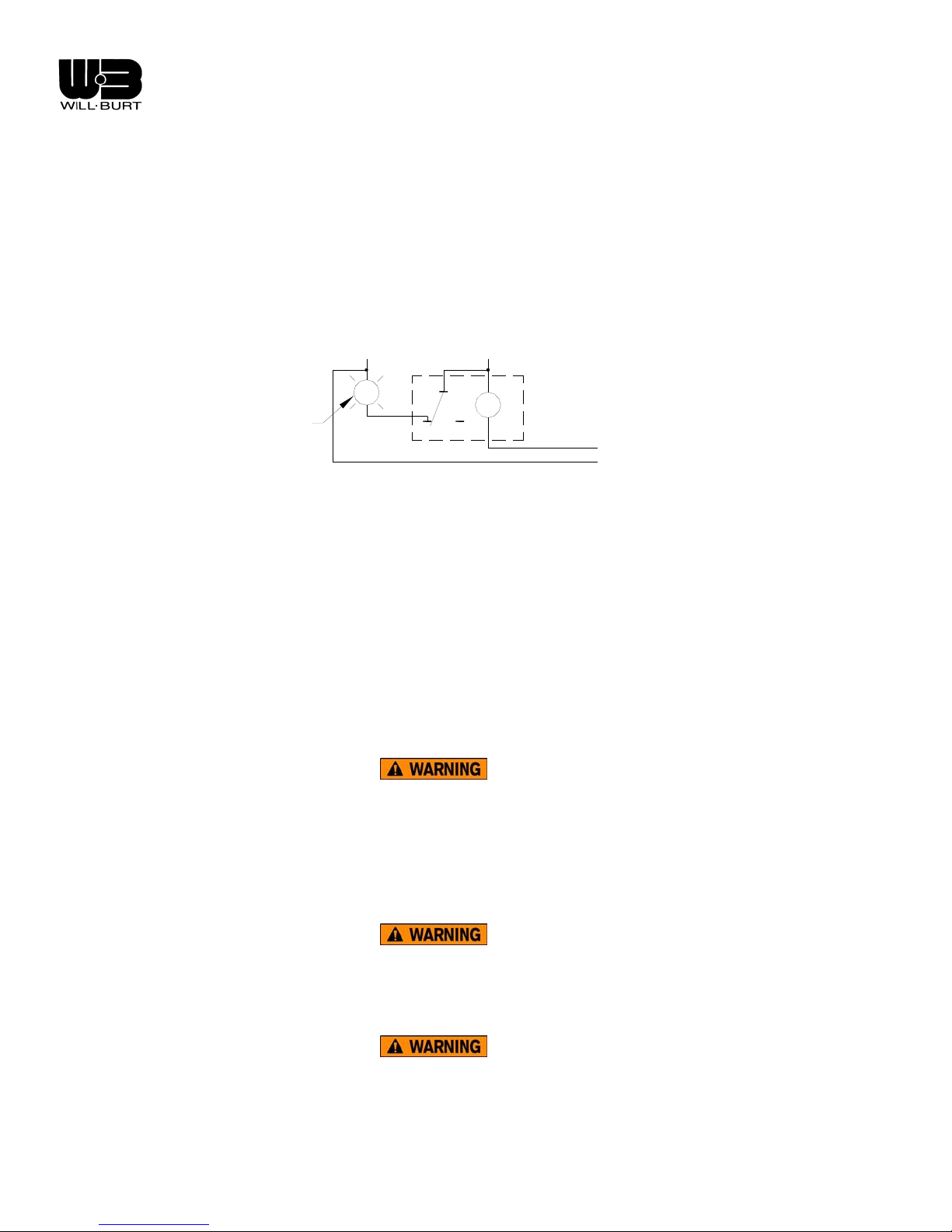
2.9 INSTALLING THE WARNING LIGHT
As required by NFPA regulations, a red flashing or rotating light, located in the driving compartm ent, must b e
automatically illuminated whenever the vehicle parking brake is not fully engaged and the light tower is
extended. The warning light is wired into the system via the interlock contact described above. A customer
provided, normally closed pilot relay should be installed on pins J4-8 and 9 of the base circuit board. See the
wiring schematics in section 4.4. A customer supplied flashing relay and lamp may then be installed in the
driving compartment such that the driver can see the lamp. One example using a Bosch relay is shown
below.
WARNING
LIGHT
TO BATTERY
( - )
R
87A
TO BATTERY
( + )
86
30
87
85
BOSCH RELAY
0 332 209 151
OR EQUAL
PIN- J4-8
PIN- J4-9
Figure 2-6 Example of Warning Light Installation
2.10 MULTIPLEX SYSTEMS OPERATING AT 24 VOLTS
When operating at 24 volts, the Night Scan Chief “chops” the voltage sent to the 12 vdc motors is the system.
As a result of this starting and stopping, voltage might be fed back through the power wires and into the
power supply. In some instances, this may lead to unexpected behavior in a multiplex system. In order to
mitigate this back feeding of voltage, an 820uF capacitor (Will Burt Part Number 204001) can be placed
across the positive and negative input terminals (TB3-5 and TB3-6) on the base circuit board. Please refer to
wiring schematic Figure 4-8. Note the direction of the capacitor for installation.
2.11 PRE-OPERATIONAL CHECK
Before beginning installation, make certain that the area is free
of overhead power lines and other unwanted sources of
electricity. Follow OSHA safety regulations when working near
energized power lines. Be sure to allow sufficient clearance on
all sides of mast to allow for side sway.
For outdoor use only. Do not use in areas that have been
classified as hazardous as defined in Article 500 of the
Do not use in the presence of flammable gases or liquids
such as paint, gasoline or solvents. Do not use in areas of
limited ventilation or where high ambient temperatures are
Revision 1 2-6
National Electric Code.
Page 21

Night Scan Chief
present. Contact with combustible materials can cause
ignition resulting in fire or explosion.
Before operating the Chief, be sure that there are no overhead obstructions and that there are no po wer
lines within 20 feet of the mast. Visually inspect the unit for any damage. If damage is apparent, do not
use the mast. Have it serviced prior to use. Check for any objects which might obstruct motion of the
mast or cause binding. Remove any material that may hinder mast function.
Revision 1 2-7
Page 22

Page 23

Night Scan Chief
CHAPTER 3
OPERATING INSTRUCTIONS
All operators must read the Operation section of this manual
and be properly trained.
Keep personnel clear of mast while during operation.
For outdoor use only. Do not use in areas that have been
classified as hazardous as defined in Article 500 of the
National Electric Code.
Do not use in the presence of flammable gases or liquids
such as paint, gasoline or solvents. Do not use in areas of
limited ventilation or where high ambient temperatures are
present. Contact with combustible materials can cause
ignition resulting in fire or explosion.
Before operating, make certain that the area is free of
overhead power lines and other unwanted sources of
electricity. Be sure to allow sufficient clearance on all sides
of mast to allow for side sway.
Do not move vehicle until mast has been securely stowed.
Revision 1 3-1
Page 24
Night Scan Chief
3.1 THEORY OF OPERATION – MECHANICAL
Night Scan Chief – Mast
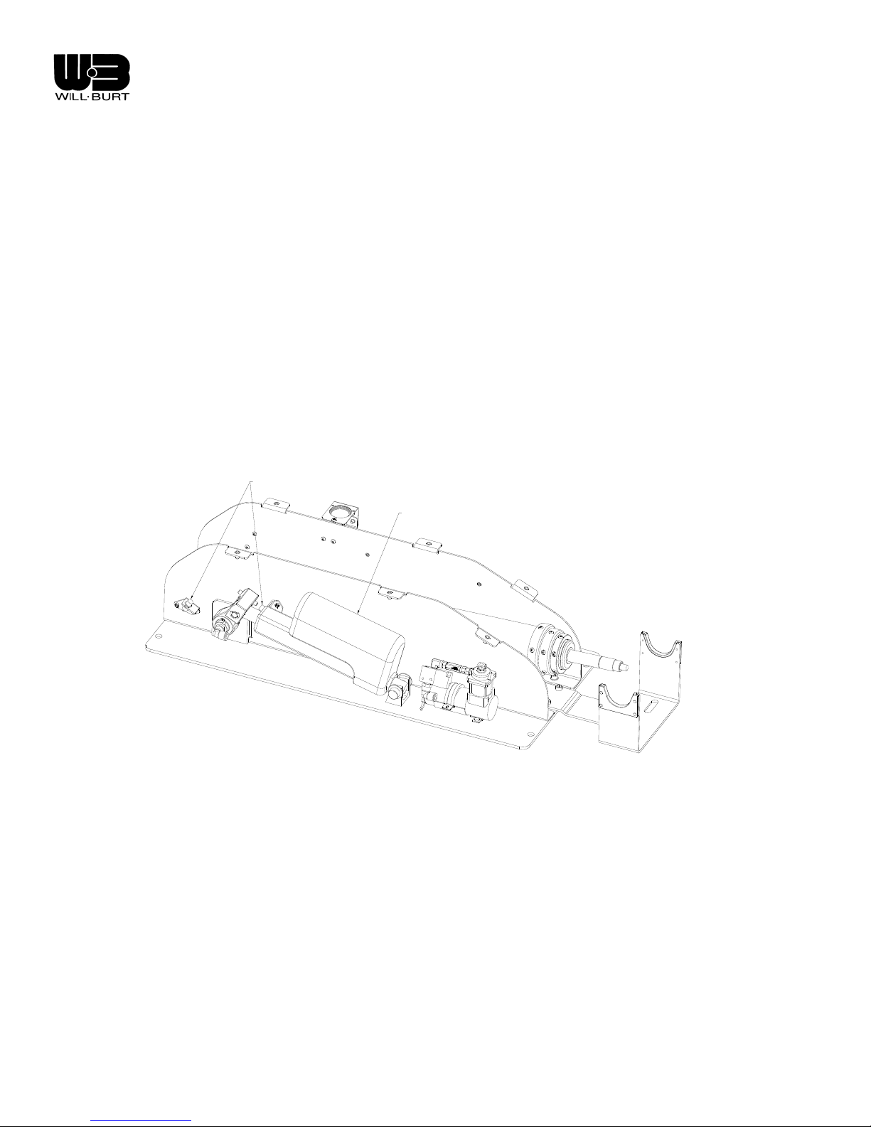
The Night Scan Chief operates using a DC powered actuator to drive the mast from nest to 90 degrees.
When at 90 degrees, a magnetic sensor detects the actuator position and prevents further driv ing of the
actuator. The sensor also notifies the operator through the Remote Control(s) that certain RCP function s
are available. The compressor assembly included in the base will receive pow er and pre s surize the mast
when the up button is depressed. If, at any time, power to the unit is lost, the exhaust valve opens,
exhausting all air from the mast.
As the mast is nested, the base control looks for indication from a magnetic switch that the mast has fully
retracted and may be safely restored to its fully nested (horizontal) position. If the “double click”
unattended stow sequence was not used, the RCP will begin the autostow sequ ence to insure that the
RCP is properly positioned for engagement with the saddle. If the autostow “double click” sequence was
used, the RCP will have properly positioned itself as the mast descended prior to horizontal nesting into
the saddle.
PROXIMITY
SWITCHES
ACTUATOR
Figure 3-1 Actuator and Proximity Sensors
RCP
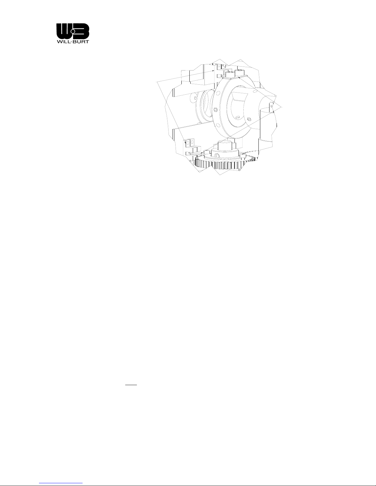
The RCP provides pan and tilt functions upon command from the Remote Control(s). DC powered gear
motors turn the shafts until an opaque flag in the assembly reaches a photo interrupter. At this time, the
LED on the Remote Control(s) for that direction of travel will go out, indicating that a limit has been
reached in that direction.
Revision 1 3-2
Page 25
Night Scan Chief
PHOTO
INTERUPTER
FLAG
Figure 3-2 Photo Interrupter and Flag
3.2 THEORY OF OPERATION – ELECTRICAL
The Chief control is based on a distributed intelligence control structure. Each main section of the Chief
has a circuit board with an embedded micro controller. These sections are: the Base, the R CP, and the
Remote Control(s). These boards “talk” to each other over a multi-drop RS-485 serial communications
link.
Another key component of the control is an initialization circuit. In an NFPA compliant installation, a
completely stowed Night Scan Chief draws zero current and cannot be extended or operated until the
initiate circuit is engaged. Included in this initialization circuit is an input for a safety interlock. This can be
used for an emergency stop, or other interlock function such as a “Park/Neutral” switch from the vehicle
transmission. Relay contacts inserted in the violet wire coming from pin J4-6 of the base circuit board
function to inhibit operation of the Chief (See schematics in section 4.4)
Additionally, a bi-stable (latching) contact closure is provided that indicates that the mast is properly
stowed. It will close when the mast is properly stowed. If the mast is not stowed, the contact will be open.
Even if the emergency stop feature is used prior to the mast completely stowing, the contact will still
remain open. If the Night Scan has been stopped using the emergency stop button or by some other
interruption of power, the initiate circuit will need to be activated again in order to continue operation.
When stowing the mast to horizontal position, the control monitors the current of the actuator. When the
mast lowers, trips the Mast Nested limit switch, and comes up against the mechanical re sistance of the
saddle; it senses it, considers itself stowed, and shuts itself down. This ensures a certain amount of preload on the RCP saddle.
If at any time during the operation of the mast an unexpected control situation occurs, the mast will stop
any movement and a fault
message will be displayed on the Remote Control(s) display. Clearing the fault
is accomplished by pushing the Push/Pull switch or momentarily interrupting power in some other way.
Then the control may be re-initiated and operated again.
3.3 PUSH/PULL SWITCH – NFPA INSTALLATIONS
All operation of a completely stowed mast must be preceded by proper initialization. The initiate switch must
be momentarily closed to power-up the Night Scan. When the Will-Burt Accessory Kit is used, the Push/Pull
switch is located on the junction box. It is used to perform two functions. First, it can be used to “initiate” the
Revision 1 3-3
Page 26

Night Scan Chief
control by pulling the switch operator. This is a momentary function, and the switch will return itself to a
neutral position on its own. Secondly, it functions as an emergency stop when the switch operator is pushed
all the way in. This is also a momentary function, and the switch will return itself to a neutral position on its
own. When using Will-Burt’s accessory kit push/pull switch, accidental initiating is extremely unlikely since it
would require pulling the switch button. Even with this, the Remote Control(s) would have to be subsequently
pushed to get any action. In the unlikely event that the initiate switch were engaged, the Night Scan will power
itself down if no Remote Control action occurs within thirty seconds. The “Push” portion of the Push/Pull
switch functions as an Emergency Stop. If it is pushed, the mast will immediately be disconnected from power
and stop.
the mast to vent.
It should be noted that prematurely disconnecting power in this way will immediately cause
Other interlock contacts could be inserted into this circuit to provide additional safety. The
control also monitors the initiate input, and if it sees that this input is present for a prolonged period of time;
the control will stop the mast and appropriate error code will be displayed (Err, 1.09). This is a preventative
measure to ensure the initiate input is not hot-wired. Once the mast has been initiated, the Remote Control
must then be used to begin raising the mast within thirty seconds or the control will shut itself down. If the
mast has been initiated and raised any amount, the control will remain powered until the mast is fully stowed,
the emergency stop function is used, or the power is somehow otherwise interrupted.
3.4 PUSH/PULL SWITCH – NON-NFPA INSTALLATIONS
All operation of a completely stowed mast must be preceded by proper initialization. The initiate switch must
be closed to power-up the Night Scan. When the Will-Burt Accessory Kit is used, the Push/Pull switch is
located on the junction box. It is used to perform two functions. First, it can be used to “initiate” the control by
pulling the switch operator. Secondly, it functions as an emergency stop when the switch operator is pushed
all the way in. When using Will-Burt’s accessory kit push/pull switch, accidental initiating is extremely unlikely
since it would require pulling the switch button. The “Push” portion of the Push/Pull switch functions as an
Emergency Stop. If it is pushed, the mast will immediately be disconnected from power and stop.
be noted that prematurely disconnecting power in this way will immediately cause the mast to vent.
It should
Other interlock contacts could be inserted into this circuit to provide additional safety.
3.5 REMOTE CONTROLS (HAND HELD)
Wired Hand Held Remote Control
• The Remote Control accepts switch activations from the operator and translates them into
serial commands for transmission to the base control board via the RS-485 link. If the operator
engages a switch, the Remote Control will appropriately send commands repeatedly as long as
the operator continues to engage that switch. The Base control will pass along appropriate
serial commands to the RCP in response to the Remote Control(s). Additionally, variou s states
of the system will be passed to the Remote Control so that button status LEDs can give proper
indication of the state of the Night Scan. An example of this is that the LED next to the “Mast
Down” button will not be lit unless it is appropriate to lower the mast. Upon first beginning to
raise the mast, it will be noted that the “Mast Down” button does not become active until a
certain amount of movement has been accomplished. This is to ensure that there is enough
downward travel available for proper stowing of the mast. If the button status LED for a
particular button is not lit, that button will not function. Another reason for a button status LED
not being lit could be an actuator reaching the extent of its travel (or limit switch).
• Two special functions are implemented in software whereby the operator can initiate an
unattended lowering and stowing of the mast, or an unattended partial raising of the mast. The
Autostow is accomplished by two rapid sequential activations of the “Mast Down” button within
a half second period of time. This automatic unattended sequence can be aborted at any time
by a single activation of the “Mast Up” button or any other button on the Remote Control(s). The
Revision 1 3-4
Page 27

Night Scan Chief
Auto-Up function is accomplished by two rapid sequential activations of the “Mast Up” button
within a half second period of time. This automatic unattended sequence can be aborted at any
time by a single activation of the “Mast Down” button or any other button on the Remote
Control(s). The Auto-Up function will only bring the Chief from the horizontal stowed position up
to the 90º position and turn the lights on. It will not raise the mast any further vertically on its
own. The Auto-Up function is not available on the non-NFPA Chief.
Wireless Held Remote Control
• The wireless remote control accepts switch activations from the operator and transmits to the base
control board. If the operator engages a switch, the Remote Control will appropriately send
commands repeatedly as long as the operator continues to engage that switch. The Base control will
pass along appropriate serial commands to the RCP in response t o the Remote Control(s). Feedback
in the form of LED’s is not available with the wireless remote control.
3.6 RAISING THE MAST
Operation of the mast using the Remote Control(s) is fairly intuitive. A typical operational sequence could
be as follows:
• Pull the Push/Pull Initiate button.
• Press and hold the “Mast Up” button on the Remote Control(s) until the mast has fully
extended.
• Press the desired Pan and Tilt buttons until the lights are facing appropriately.
• Press the Light and Aux light buttons momentarily to turn the desired lights on and off.
• Press the “Mast Down” button until the mast has completely stowed.
Note: In the Night Scan Chief, during the process of raising the mast, the mast will first be inclined to a
position perpendicular to its mounting surface by an actuator. Once the control senses it is in this position,
air pressure will be applied to the tube sections to raise the mast further into the air. Lowering the mast is
in reverse order. Air is vented from the tube sections reducing its height. Then the actuator declines the
mast until it is finally stowed.
Auto-up Function (wired handheld remote control only)
The “Auto-up” function can be initiated by giving two quick successive depressions of the “Mast Up”
button (within ½ second). The mast will then raise to the 90° position and automatically turn on both
banks of lights. This automatic sequence can be aborted by pushing any of the buttons on the Remote
Control(s) at any point during the Auto-up sequence. The mast will not extend up by itself, but will await
further operator input from the Remote Control(s).
3.7 AIMING THE REMOTE CONTROL POSITIONER
The positioner can be “aimed” by utilizing the pan and tilt buttons located on the Remote Control(s). The
Pan Left and Pan Right buttons allow horizontal movement, while there are independent Tilt Up and Tilt
Down functions for vertical adjustment of each side of the RCP.
3.8 STOWING THE MAST
There are two methods of stowing the mast. The normal method involves pressing and holding the “Mast
Down” button until the mast is fully stowed and the control shuts itself off. A second method, available on
Revision 1 3-5
Page 28

Night Scan Chief
the hardwired remote control) involves giving two quick successive depressions of the “Mast Down”
button (within ½ second). This will initiate an unattended complete stowing of the mast. This Auto-stow
mode can be interrupted and canceled at any time by pressing any of the buttons on the Remote Control.
Note: To ensure proper seating of the RCP in Night Scan Chief saddle, the control watches for an
increase of current from the actuator. Once this has been satisfied, the control will shut itself off on NFPA
compliant installations. For non-NFPA installations, it will be necessary to manually shut off power by
pushing the Push/Pull switch on the junction box. If by chance there is no increase in current and the
actuator shuts off because of its internal limit switch, a fault message will be displayed.
Once the control is shut off, the Night Scan is totally disconnected from power, and the “Mast Stowed”
safety interlock contact closes signaling it is safe to move the vehicle.
Be sure that no buttons are
illuminated on the remote after you believe it is stowed. Illuminated buttons indicate that the unit
stowed. After making certain that the unit is properly stowed in the saddle, unplug the remote
is not
control and stow it where it will not be damaged in transport. Unplugging the remote will remove any
possibility that the Chief could become active and extend unexpectedly.
3.9 EMERGENCY STOW (LOSS OF POWER):
Make sure all power has been disconnected from the Night
Scan prior to manually lowering mast.
Make sure lights have cooled completely before manually
panning or tilting the RCP.
In the event of power loss or an unrecoverable error condition, the Night Scan Chief will automatically
exhaust all air and nest. However, the mast will NOT return to its fully stowed, horizontal position. This
must be accomplished manually. It is required that two people perform this operation as the mast is very
heavy and can cause severe injury or death if not done with extreme caution. It may be necessary to
manually pan the RCP so that when it is manually nested, the lights do not make contact with the
mounting surface or the saddle. To manually pan the unit, firmly grasp the RCP by the horizontal shafts
slowly rotate to a point perpendicular to the length of the base. Additionally, it may be necessary to
and
manually tilt the lights to prevent damage when stowing the mast. Tilt the lights by grasping the top and
bottom of the light bar and
slowly rotating the lights such that they face down when fully stowed.
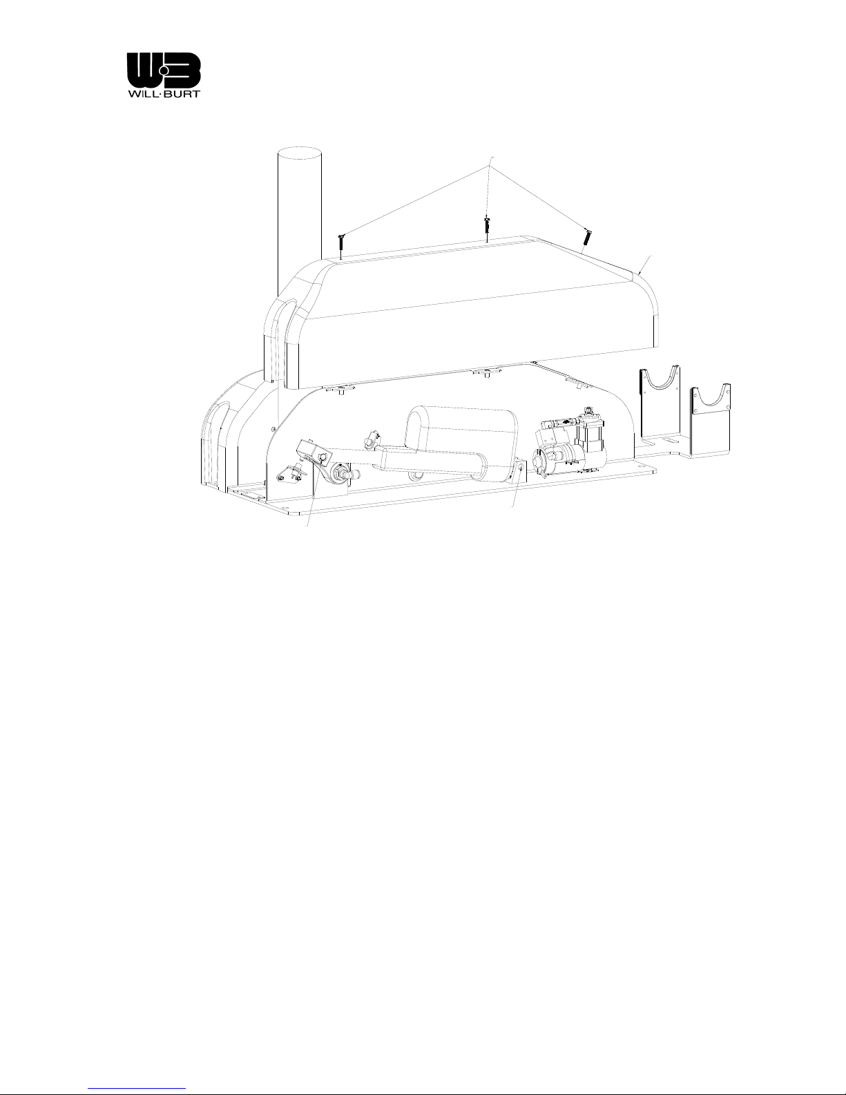
Support the mast before removing shoulder screw! Once
removed, the mast and light assembly is free to fall.
Remove the right side base cover (opposite look up light). Secure the mast in an upright position to
prevent it from falling freely. Remove the knurled shaft from the bottom of the actuator. CAREFULLY
lower the mast down into the saddle. Secure the mast in this nested position before moving the vehicle.
Revision 1 3-6
Page 29
Night Scan Chief
COVER SCREWS
RIGHT SIDE
COVER
KNURLED
PIN & E-CLIP
PIN
Figure 3-3 Cover and Screw Removal for Manual Stow (Night Scan Chief only)
Revision 1 3-7
Page 30

Page 31

Night Scan Chief
CHAPTER 4
MAINTENANCE AND SERVICE INSTRUCTIONS
4.1 INTRODUCTION
This section of the manual describes routine maintenance procedures and covers gen eral service
information. Refer to Chapter 5 for exploded views of the Night Scan Chief and the accompanying Table s
with item descriptions and part numbers, which may be used for ordering replacement parts.
4.2 SCHEDULED MAINTENANCE
Cleaning and Lubrication - Mast
Will-Burt pneumatic telescoping masts should be cleaned and lubricated o n a regular basis to insure
smooth operation and to prolong useful life. This maintenance should be perform ed typically about once a
month depending upon local environmental conditions and frequency of use. Signs that cleaning and
lubrication are needed can be:
• A noticeable gritty film on the exterior surfaces of the mast sections
• Erratic extension or retraction of the mast
• Noisy operation of the mast
• Sticking of one or more mast sections when mast is extending or retracting
A pneumatic telescoping mast is a pressure vessel.
Caution must be exercised to stay clear when the mast
is being extended. Do not lean directly over the mast.
Proper eye protection should be worn when working on
the mast.
PROCEDURE:
1. One person operating hand held remote control should slowly pressurize the mast just enoug h to
extend the top mast section. Another person may need to hold down the larger mast section
collars to assure the proper sequence of extension. Release “Mast Up” button as soon as the
mast section is up.
2. Wipe down the extended mast section u s ing a non-abrasive cleanser or solvent such as lacquer
thinner. Do not allow the cleaning fluid or solvent to run down inside the collar.
3. Repeat steps 2 and 3 for the next larger mast section .
4. Inject approximately 1/2 oz. of TMD Mast Lubricant* or a lightweight machine oil into the wee p
hole (drain) of the exposed mast section. The weep holes are located app roximately 10 inches
below the collar on each tube except the top one.
5. Repeat steps 2, 3 and 5 for each of the remaining mast sections.
Revision 1 4-1
Page 32

Night Scan Chief
6. Exhaust the mast completely. Allow several minutes for the lubricant to settle and spread around
the wear ring and seal at the bottom of each mast section.
Keep hands clear of the descending collars while the mast is
being lowered to avoid pinching.
7. Extend the mast again one section at a time in the same sequence (smallest to largest). Wipe off
any excess lubricant which flows out of the weep holes.
NOTE: Do not lubricate the exterior of the mast, as this will cause it to attract dust and
contaminants from the air.
* TMD Mast Lubricant is specifically formulated for cold weather use, but is suitable for year around use.
Regular winter maintenance and the frequent use of TMD Mast Lubricant should signifi cantly reduce the
potential for mast freeze ups.
Cleaning Night Scan Base and Remote Control Positioner (RCP)
Make sure lights are completely cool before attempting to
clean.
The exterior of the RCP and Night Scan base should be wiped down periodically to remove dirt and road
grime using a soft cloth or sponge and a mild solution of soapy water. The lenses of the lights should be
cleaned using standard glass cleaner and a soft towel.
4.3 ADJUSTMENTS
Adjusting the 90º Proximity Switch
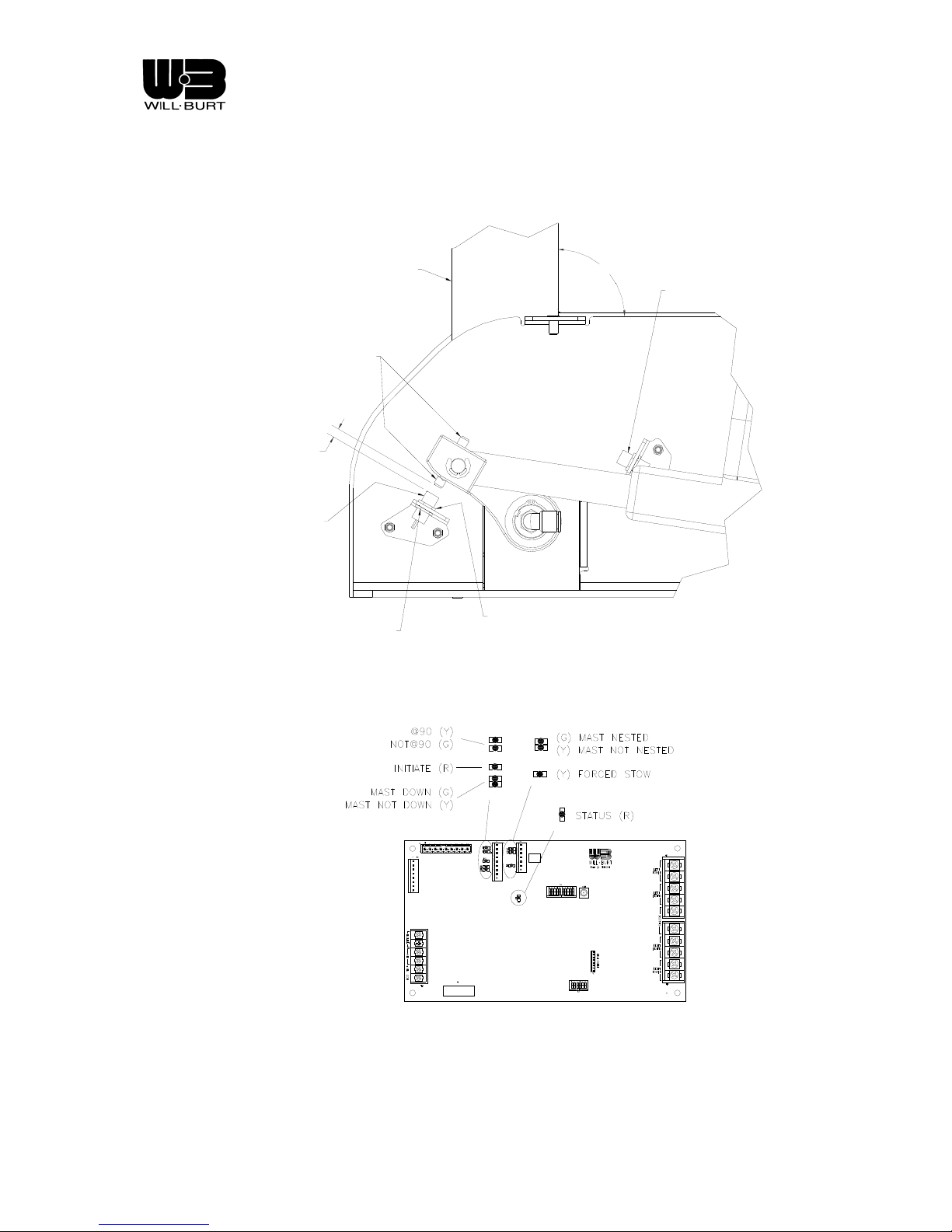
The proximity switch (sensor) is intended to stop the actuator when the mast is at 90 degrees when being
raised. It senses the magnet that is threaded into the clevis and signals the base circuit board to cut
power when the actuator is in the correct position. In the event that this switch needs adjusted (i.e. after
replacing the actuator) to stop the mast at 90 degrees, the following procedure must be followed. Use
Figure 4-1 as an aid to identify the components.
1. Make certain that the Chief is level.
2. Remove the right hand base cover (opposite the loo k up light)
3. Loosen the upper jam nut to lower the switch approximately 1/8”.
4. Raise the mast to 90 degrees. Verify that the mast is plumb using a level or check to see that it is
square to the sheet metal side plate on the base.
5. Raise the switch until it senses the actuat or. This will be indicated by 1) an audible “click” of the
exhaust valve closing, 2) lights on the hand held will change state, indicating that RCP functions are
available and 3) the LED on the base circuit board will change from green to yellow.
6. Secure the switch in position using the upper and lower jam nuts.
Revision 1 4-2
Page 33
Night Scan Chief
7. Cycle the mast several times, checking that the mast is plumb each time. Adjust the switch if
necessary.
8. Replace cover.
GAP
PROX SWITCH
MAST
MAGNET
UPPER
LOWER
JAM NUT
JAM NUT
Figure 4-1 Proximity Switch Adjustment
90°
PROX SWITCH
Revision 1 4-3
S2
Figure 4-2 LED Location and Function
Page 34

Night Scan Chief
Adjusting the Magnetic Switch
The Magnetic Switch is located on the mast base tube. In the Night Scan Chief, the magnetic switch
senses a magnet located in the top tube and serves to indicate that the mast has exhausted all air and
that it is safe to nest into the saddle. If the switch is out of adjustment, it will prevent the mast from
nesting to the saddle from the 90 degree position.
by verifying that the collars are stacked with no gaps between them.
It is important that the mast has properly nested
If the collars are not properly
stacked see Table 4-5 for further instructions. If the switch is found to require adjustment, it will most
commonly need to be moved upward (toward the RCP) on the mast. The magnet is located at the lower
end and side of the top tube. It is not visible outside the mast.
The following procedure must be followed to adjust the magnetic switch.
1. Loosen the band clamp securing the swi t ch to the base tube. Move the switch up approximately 1/8”
and tighten band clamp.
2. Initiate the mast, if necessary, and press the down button the hand held remote. If the mast does not
nest, repeat the adjustment until it does. A small piece of steel or iron filings may be used to help
locate the magnet.
3. If repeated attempts do not succeed, hold a magnet u p to the switch and press the do wn button. If
the mast begins to nest, continue repeating the adjustment until the switch has sensed the magnet.
4. If the mast will not nest when a magnet is held to the switch, ch eck the wiring to the circuit board for
loose or disconnected wires. See schematics in section 4.4. If the wiring is intact, replace the
magnetic switch.
Resetting the RCP Home Position
The Chief unit is shipped with the lights in home position. Home position is established by setting small
flags in the RCP that engage photo interrupters on the RCP board. It orients the lights such that the light
bars are parallel to the axis of the mast and are facing downward when nested. On all models, the RCP
shafts should contact the saddle simultaneously during nesting when correctly set. It should be noted
that having the RCP covers off could cause improper RCP operation when outdoors. This procedure
should be performed indoors. To set the home position, the following procedure must be obse rved.
DISCONNECT ALL AC POWER TO THE CHIEF!
1.
2. Initiate the mast and raise it to the 90-degree position. The hand held remote should show both left
and right tilt up functions are available and the pan left function is available.
3. Remove the RCP covers to access the flags.
4. Refer to Figure 4-3 for reference. The flags are attached to the timing rings on the horizontal and
vertical shaft gears.
5. Once the set screws are loose, pan and tilt the unit to the correct ho me position. Be careful that the
flags do not come into contact when panning and tilting, they may become bent.
6. It is important that the flags engage the correct photo interrupter when setting the home position, see
Figure 4-3. Turn the timing ring on the right horizontal shaft such that it rotates down toward the
upper photo interrupter. As you approach the interrupter, watch the wired hand held remote. As
soon as the tilt down LED goes out, stop rotating the ring and tighten the set screw. To set the pan
home position, turn the timing ring counterclockwise (looking from above the RCP) until the pan right
LED goes out. Tighten the adjustment screw to secure the ring.
7. Pan and tilt the unit until the second set screw in each ring is accessible and tighten.
8. Stow the mast, watching for the lights to be oriented as de scribe d in the beginning of this section.
Revision 1 4-4
Page 35

Night Scan Chief
9. Initiate and raise the mast to 90 degrees. Repla ce the RCP cover.
+++
J4
POINTERS @ HOME POSITION
+++
+
+
Figure 4-3 Flag Settings
DIP switch setting
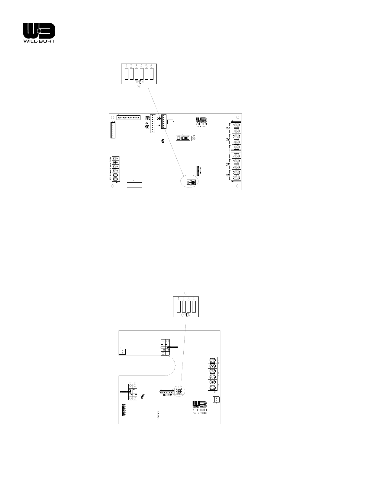
Chief base boards require that the DIP switch be set appropriately to determine operational mode. RCP
boards require that the DIP switch be set appropriately to determine operational mode. This takes the place of
setting the operational mode through software by changing a variable.
To set the operational mode for the Base board, locate the DIP switch S2 (see Figure 4-4) and set the DIP
switch as follows:
• Position 1 - DO NOT CLOSE
• Position 2 - Close if the system is a non-NFPA compliant installation
• Position 3 - Close if the system does not have an RCP
• Position 4 - DO NOT CLOSE
• Position 5 - DO NOT CLOSE
• Position 6 - DO NOT CLOSE
Revision 1 4-5
Page 36
Night Scan Chief
S2
Figure 4-4 DIP switch location: Chief base board
To set the operational mode for the RCP board, locate the DIP switch S1 (see Figure 4-5) and set the DIP
switch as follows:
• Position 1 - Close to cause the RCP to self stow if there is an error.
• Position 2 – DO NOT CLOSE.
• Position 3 – DO NOT CLOSE
• Position 4 – DO NOT CLOSE
+++
J4
+++
+
+
Figure 4-5 DIP switch location: Chief RCP board
Revision 1 4-6
Page 37
Night Scan Chief
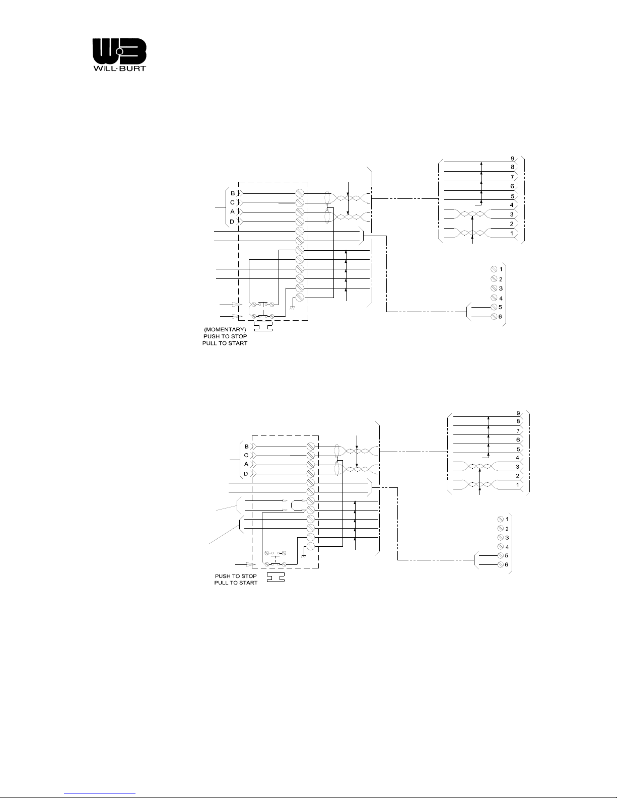
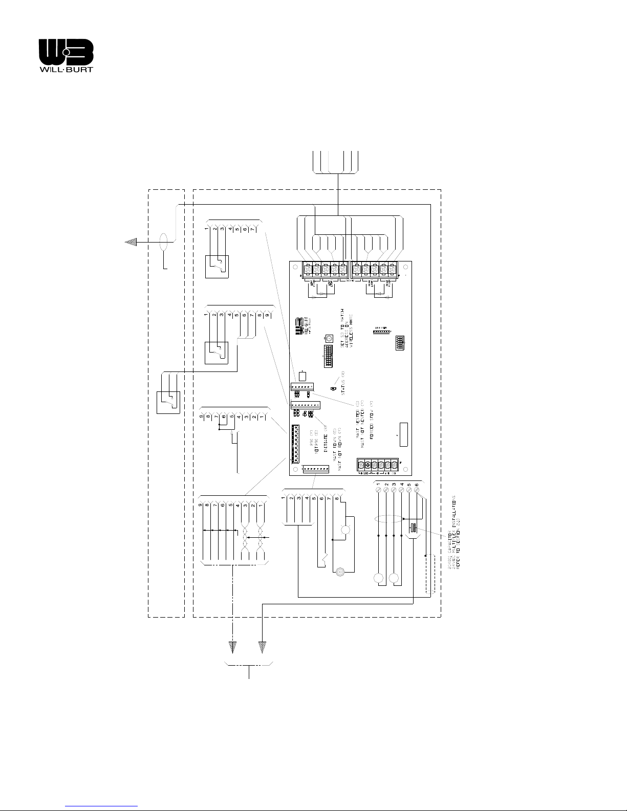
4.4 SYSTEM SCHEMATICS
A system schematic is given in order to aid in electrical troubleshooting as outlined in the following section.
BLU
BRN
RED
BLK
GRY
VIO
GRN
BLK
WHT
BLK
RED
J4
TB3
TO HHRC
BATTERY (+) 10 GA
BATTERY (-) 10 GA
TO CUSTOMER
VEHICLE INTERLOCK
(2 AMP. MAX. LOAD)
CLOSED CIRCUIT
WHEN STOWED
SEE SECTION 2.12
KA-3
KA-5
20 GA TWISTED PAIRS
J1
RED
A
BLK
B
WHT
C
BLK
D
RED
E
BLK
F
GRN
G
GRY
H
BRN
J
BLU
K
VIO
L
18 GA
(init)
(kill)
(com)
4032504 16 FT CABLE
4032505 30 FT CABLE
4032506 50 FT CABLE
18 GA
20 GA TWISTED PAIRS
Figure 4-6 NFPA Handheld Remote Wiring
TO HHRC
BATTERY (+) 10 GA
BATTERY (-) 10 GA
REMOVE G-H JUMPER IF
PARKING BRAKE INTERLOCK
IS USED. CLOSED WHEN
BRAKE "ON"
TO CUSTOMER
VEHICLE INTERLOCK
(2 AMP. MAX. LOAD)
CLOSED CIRCUIT
WHEN STOWED
J1
KA-1
(SHOWN IN PULLED POSITION)
20 GA TWISTED PAIRS
RED
A
BLK
B
WHT
C
BLK
D
RED
E
BLK
F
GRN
G
GRY
H
BRN
J
BLU
K
VIO
L
18 GA
(init)
(kill)
(com)
4032504 16 FT CABLE
4032505 30 FT CABLE
4032506 50 FT CABLE
Figure 4-7 Non-NFPA Hand Held Remote Wiring
18 GA
20 GA TWISTED PAIRS
RED
BLK
BLU
BRN
GRY
VIO
GRN
BLK
WHT
BLK
RED
J4
TB3
Revision 1 4-7
Page 38
Night Scan Chief
SUPPLIED
CUSTOMER
LEFT LIGHT POWER
L2
L1
J2
L2
L1
|3|
BLU
BLK
TO RCP
BRN
MAST @ 0
J3
|4|
INTERNAL COIL CABLE
BLK
RED
BLU
WHT
BLK
BRN
MAST@90
|5|
GND
RIGHT LIGHT POWER
L2
L1
GND
GND
GND
|6|
ANTENNA
S3
|9|
|10|
YEL/GRN
YEL/GRN
TB2
TB1
L1
L2
|7|
|8|
S2
BLK
RED
WHT
J4
APPLICATIONS
MAST DOWN
J4
VIO
BLU
BRN
GRY
GRN
MAST
BASE
WITH NO J-BOX
BRAKE "ON"
CLOSED WHEN
REMOVE JUMPER
IF PARKING BRAKE
INTERLOCK IS USED.
|14|
BLK
BLK
RED
WHT
18 GA
20 GA TWISTED PAIRS
4032504 16 FT CABLE
4032505 30 FT CABLE
4032506 50 FT CABLE
10 GA
J2
J3
J4
J5
J5
|13|
|12|
|11|
LOOK-UP LIGHT
WHT/RED
_
+
DOWN
VALVE
(OPT)
BEEPER
TB3
TB3
BLK
RED
BLK 1
WHT 2
BLK 2
WHT 1
+
WHT/BLK
4206101 CABLE
BRN
BLU
ORG
BLK
M
M
INCLINATION MOTO R
AIR COMPRESSOR
SHIELD
Figure 4-8 Night Scan Chief Base Wiring
Revision 1 4-8
BOX
JUNCTION
Page 39
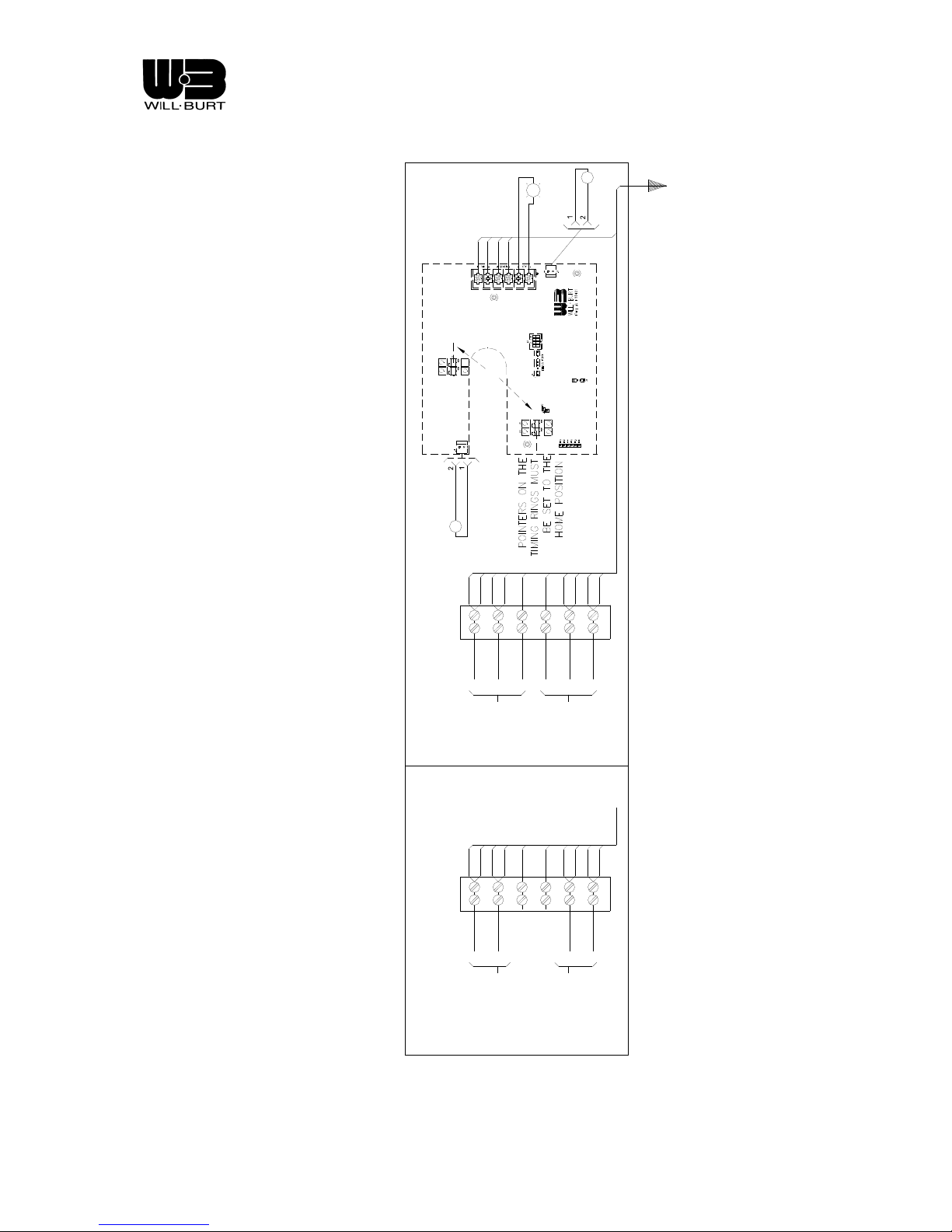
Night Scan Chief
STROBE
|13|
|12|
|11|
|14|
TB1
+
+
+
+
J4
POINTERS @ HOM E POSITION
18GA RED
18GA BLK
PAN
|8|
|7|
|10|
|9|
YEL/GRN
18GA RED
18GA BLK
J1
J1
S1
+
+
+
+
|5|
|6|
|3|
|4|
YEL/GRN
OPTIONAL
TILT
TO MAST
RED
WHT
GRN/YEL
GRN/YEL
WHT
RED
LIGHTS
TO RIGHT
|8|
|7|
|10|
|9|
YEL/GRN
RED
BLK
LIGHTS
TO LEFT
RCP
|5|
|6|
|3|
|4|
YEL/GRN
BLK
RED
DC LIGHTS AC LIGHTS
LIGHTS
TO RIGHT
LIGHTS
TO LEFT
Figure 4-9 Night Scan Chief Remote Control Positioner (RCP) Schematic
Revision 1 4-9
Page 40

Night Scan Chief
4.5 TROUBLESHOOTING ELECTRICAL
Operating Environment
One of the most common causes of improper operation is trying to operate outside of the stated system
requirements. (See section Table 1-1for DC power requirements). A good method of checking the voltage
at the Chief is to connect a voltmeter to the wires in the junction box powering the Remote Control(s)
(pins B and C of J1 (see schematics in section 4.4). This will give a good indication of power loss across
the DC cabling. For long runs, it may be necessary to add an intermediate junction box in the DC cabl e so
that DC power can be applied closer to the Chief.
Fault Codes
Fault codes are presented on the LED alphanumeric display on the wireless remote control. Whe n faults
occur, all operation ceases. Faults may only be cleared by killing power to the Chief. This may be
accomplished by momentarily pushing in the Push/Pull switch and then re-initializing. Additionally, the
fault code is also flashed by a red status LED located on the Base board. For instance, if the fault code
were 3,07, then the LED would flash three times, pause, flash seven times, pause longer, and the repeat
the flash sequence. During normal operation, the LED should flash a slow steady on/off pattern. The
codes are as follows:
4.5.1.1 Base Board
The Base board is located in the base of the mast and is assigned unit number one (1 ). The Base
board may generate the messages of Table 4-1:
Table 4-1. List of Base Board Faults
Message Meaning Root Issue Potential Causes
Err 1,01 Mast Down
Magnetic Switch
Wiring Error
The Mast Down
Magnetic Switch
appears to have its
complimentary
outputs wired
backwards This
switch is located on
the side of the mast.
This check is only
made at power-up
when the mast
thinks it is nested.
The wires on pins 5
and 6 of J3 may
need to be swapped.
The magnetic switch
not being energized
could also cause it.
Place a magnet
close to the switch to
check before
changing wiring.
Err 1,03 Excessive
actuator current
draw during
nesting
The current drawn
by the actuator has
exceeded a level of
current greater that
that required for
proper nesting
Either a rigid object
is in the way of the
mast as its nesting,
or the Mast Nested
Proximity Switch is
not being activated
as the mast
approaches the
saddle. Check for
foreign objects in the
Revision 1 4-10
Page 41

Night Scan Chief
mast path, and
confirm that the
proximity switch is
being properly
activated.
Err 1,07 Unrecoverable
Communication
Error
The Base board has
not sent out
communications
recently
Err 1,08 Software Fault Internally detected
error
Err 1,09 Initiate
Pushbutton
The Initiate input has
been closed for too
long.
Err 1,10 EEPROM Life More than 20,000
writes have been
made to a particular
EPROM location
Err 1,11 Saddle Location The internal linear
actuator limit switch
has opened before
preload occurred
Indicates a software
problem. Notify WillBurt
Indicates a software
problem. Notify WillBurt
Wiring Short in the
DC cable or
incorrect DIP switch
setting (S2)
Will only occur when
the mast has had in
excess of 20,000
cycles which is
unlikely to happen.
Replace the base
board.
The saddle is too
low with respect to
the Chief base. Shim
the saddle up as
needed. Refer to
section 2.4 for
flatness
requirement.
Err 1,12
Actuator 90
°
Proximity Switch
Disagreement
The proximity switch
sensing the mast
actuator at 90
° has
conflicting
complementary
outputs.
There may be a
wiring problem, or a
defective proximity
switch. Check the
voltages at J3 pins 1
and 3 with respect to
pin 2. These two
voltages should be
opposite of each
other as the
proximity switch is
activated and
inactivated. The
voltages should be
close to battery
voltage or close to
ground. If they are
not, replace the
actuator 90
°
proximity switch.
Refer to system
Revision 1 4-11
Page 42

Night Scan Chief
schematics in
section 4.4
Err 1,13 Mast Nested
Proximity Switch
Disagreement
Err 1,14 Mast Down
Magnetic Switch
Disagreement
The proximity switch
sensing the mast
actuator at almost
nested position has
conflicting
complementary
outputs.
The magnetic switch
sensing the mast is
lowered (referring to
tube set) has
conflicting
complementary
outputs.
There may be a
wiring problem, or a
defective proximity
switch. Check the
voltages at black
and white wires with
respect to the blue
wire. These two
voltages should be
opposite of each
other as the
proximity switch is
activated and
inactivated. The
voltages should be
close to battery
voltage or close to
ground. If they are
not, replace the
actuator almost
nested proximity
switch. Refer to
system schematics
in section 4.4
There may be a
wiring problem, or a
defective proximity
switch. Check the
voltages at J3 pins 5
and 7 with respect to
pin 6. These two
voltages should be
opposite of each
other as the
magnetic switch is
activated and
inactivated. The
voltages should be
close to battery
voltage or close to
ground. If they are
not, replace the
Mast Down switch.
Refer to system
schematics in
section 4.4
Err 1,15
Actuator 90
Proximity Switch
Wiring Error
Revision 1 4-12
°
The proximity switch
sensing the mast
actuator at 90
°
appears to have its
complimentary
This check is only
made at power-up
when the mast
thinks it is nested.
The wires on pins 1
Page 43

Night Scan Chief
Err 1,16 Mast Nested
Proximity Switch
Wiring Error
outputs wired
backwards
The proximity switch
sensing the mast
actuator at almost
nested position
appears to have its
complimentary
outputs wired
backwards
and 3 of J3 may
need to be swapped.
The proximity switch
not being energized
could also cause it.
Place a magnet
close to the switch to
check before
changing wiring.
Refer to system
schematics in
section 4.4
This check is only
made at power-up
when the mast
thinks it is nested.
The black and brown
wires on the
proximity switch may
need to be swapped.
The proximity switch
not being energized
could also cause it.
Place a magnet
close to the switch to
check before
changing wiring.
Refer to system
schematics in
section 4.4
Revision 1 4-13
Page 44

Night Scan Chief
4.5.1.2 RCP Board
The remote control positioner (RCP) board is located in the positioner at the top of the mast and is
assigned unit number two (2). It should be noted that having the RCP covers off can cause
improper RCP operation, especially outdoors. The RCP board may generate the messages of
Table 4-2:
Table 4-2. List of Remote Control Positioner Board Faults
Message Meaning Root Issue Potential Causes
Err 2,01 Pan Limit
Overlap
Both pan
photosensors are
blocked
simultaneously
Err 2,02 Tilt Stuck The state of the tilt
photosensor has
not changed even
though the motor
has been told to
move for some
period of time
Err 2,04 Pan Stuck The state of the
pan photosensors
have not changed
even though the
motor has been
told to move for
some period of
time
Foreign material in one
of the photosensors or
faulty photosensor.
Check to make sure
there is no foreign
material in the
photosensors. Clean
with a soft cloth. If this
does not get rid of the
fault, replace RCP board
Something is preventing
movement of tilt
mechanism or the motor
is defective. Check to
see if voltage is being
applied to the tilt motor.
If it is, replace the
gearmotor. Otherwise,
the problem is in the
photosensor on the RCP
board. Replace RCP
board
Something is preventing
movement of pan
mechanism or the motor
is defective. Check to
see if voltage is being
applied to the pan motor.
If it is, replace the
gearmotor. Otherwise,
the problem is in the
photosensor on the RCP
board. Replace RCP
board
Revision 1 4-14
Page 45

Night Scan Chief
Err 2,07 Unrecoverable
Communicatio
n Error
The RCP board
has not sent out
communications
recently
Err 2,08 Software Fault Internally detected
error
Err 2,09 Tilt Up Limit The tilt down
photosensor was
made before the
up photosensor
indicating wrap
around or the up
photosensor is
linear or defective
Bad connection in
communications link, or
RCP is not powered or is
inadequately powered.
Make sure the power at
the RCP board is at
least 10.5 volts. Check
continuity of the internal
coiled cable between the
base board and the RCP
board (see system
schematics in section
4.4)
Indicates a software
problem. Notify Will-Burt
Check to make sure the
tilt flag is not located in
between the two
photosensors. If it is,
slowly move the left light
bank by hand (with
power off) until it is in the
proper position.
Readjustment of the flag
may be necessary to set
the proper home
position. If the flag is not
in between, replace the
RCP board
Err 2,10 Tilt Down Limit The tilt up
photosensor was
made before the
down photosensor
indicating wrap
around or the
down photosensor
is linear or
defective
Check to make sure the
tilt flag is not located in
between the two
photosensors. If it is,
slowly move the left light
bank by hand (with
power off) until it is in the
proper position.
Readjustment of the flag
may be necessary to set
the proper home
position. If the flag is not
in between, replace the
RCP board
Revision 1 4-15
Page 46

Night Scan Chief
Err 2,13 Pan Right
Limit
The left pan
photosensor was
made before the
right photosensor
indicating wrap
around or the right
photosensor is
linear or defective
Err 2,14 Pan Left Limit The right pan
photosensor was
made before the
left photosensor
indicating wrap
around or the left
photosensor is
linear or defective
Check to make sure the
pan flag is not located in
between the two
photosensors. If it is,
slowly move the RCP
head by hand (with
power off) until it is in the
proper position.
Readjustment of the flag
may be necessary to set
the proper home
position. If the flag is not
in between, replace the
RCP board
Check to make sure the
pan flag is not located in
between the two
photosensors. If it is,
slowly move the RCP
head by hand (with
power off) until it is in the
proper position.
Readjustment of the flag
may be necessary to set
the proper home
position. If the flag is not
in between, replace the
RCP board
Err 2,15 Tilt Limit
Overlap
Both tilt
photosensors
appear to be
blocked
simultaneously
Foreign material in one
of the photosensors or
faulty photosensor.
Check to make sure
there is no foreign
material in the
photosensors. Clean
with a soft cloth. If this
does not get rid of the
fault, replace RCP board
Revision 1 4-16
Page 47

Night Scan Chief
4.5.1.3 Remote Control(s) Board
The handheld remote control board is located in the handheld unit and is assigned unit number
three (3). The Remote Control board may generate the messages of Table 4-3:
Table 4-3. List of Remote Control Board Faults
Message Meaning Root Issue Potential Causes
Err 3,07 Unrecoverable
Communicatio
n Error
The Remote Control
board has not
received
communications
from the base board
recently
Err 3,08 Software Fault Internally detected
error
Bad or improper
connection in
communications link,
or Remote Control is
not properly powered.
Check continuity of
the data lines from
the DC power cable
connector to the
Remote Control
connector. Refer to
system schematics in
section 4.4. Check to
make sure that the
base board software
is 2.6 or newer. Refer
to section 0 on how
to check software
revision level. Also
check that the shield
in the junction box
has a good electrical
connection all the
way to the frame rail.
Indicates a software
problem. Notify WillBurt
Revision 1 4-17
Page 48

Night Scan Chief
Warning Codes
Warning codes are presented on the LED eight-digit alphanumeric display. The codes are a combination
of numbers that identify both the general location of the warning, and the type of warning. The first of two
numbers is a single digit number indicating which board. The second number is a two-digit number
indicating the warning. Warning codes differ from Fault codes in that they do not require clearing. If the
condition causing the warning goes away, so does the warning. At that point, normal operation continues.
The codes are as follows:
Table 4-4. List of Warning Codes
Message Meaning Root Issue Potential Causes
WRN
1,04
Lookup Light The output driving
the Lookup light
does not seem to
have a light hooked
to it. (The measured
current is too low.)
Burned out bulb.
Broken wire.
Revision 1 4-18
Page 49

Night Scan Chief
4.6 TROUBLESHOOTING MECHANICAL
Table 4-5. Mechanical Troubleshooting
Symptom Root Issue Troubleshooting Sequence
Mast sticking
during extension or
retraction
Mast leaks down
when extended
Erratic or noisy
when raising to 90
degrees
RCP continually
pans or tilts
Pan or tilt motor will
not respond with no
errors displayed on
Remote Control(s)
Mast fails to fully
nest in saddle and
disconnects power
Mast is dirty and/or requires
lubrication.
1) Clean and lubricate mast.
2) If condition continues, mast requires
overhaul.
Air leak in mast or
valve/compressor assembly.
Use a soapy water solution to pinpoint the leak.
If the mast is leaking, it will require new seals.
If the valve or compressor assembly is leaking
at a fitting, remove the fitting, clean and reinstall
using thread tape or sealant. Replace a faulty
valve or compressor.
Bent or worn actuator or pivot
Replace damaged component
shaft
Bent flag in RCP 1) Remove RCP cover straighten or replace
flag.
2) Make sure wiring is not wound tight. Reset
home position
Broken or loose motor wire lead
or faulty motor
Binding of actuator, software
fault or control erroneously
sensed an increase in current
1) Reconnect wire lead
2) Replace motor.
1) Check that base board has software
version 2.6 or later. See section 0 for
verifying revision. Contact Will-Burt if
update is required.
Mast will not begin
to lower from 90
Mast tube sections do not fully
collapse
°
position
Mast will not begin
to lower from 90
Magnetic switch band clamped
to mast is not made
°
position
Revision 1 4-19
2) See Table 4-1, Table 4-2 and Table 4-3 for
software fault codes.
3) Check actuator for binding. Replace
actuator if binding.
1) Extend and retract mast.
2) Check tube sections for damage.
3) Internal coil cord may be binding, contact
Will-Burt.
1) Magnetic switch is may be out of
adjustment. Loosen clamp and slide switch
up and down the mast until contact is
established.
2) Check wiring
3) Replace defective magnetic switch.
Page 50

Page 51

Night Scan Chief
CHAPTER 5
PARTS LIST
5.1 PART LISTS
Table 5-1. Night Scan Chief Base Assembly Parts List
Mark No. Description Part Number
1 Base Plate 4121702
2 Base Circuit Board 4118301
3 Saddle Assembly 4122201
4 Compressor Assembly 4141101
5 Actuator 4136302
6 Mast Assembly, 6 ft 4142204
Mast Assembly, 7.5 ft 4142202
7 Left Side Plate 4122702
8 Right Side Plate 4122802
9 Interface Panel 4122902
10 Look Up Light Assembly 913422
11 Mast Magnetic Switch Assembly 915519
12 Tube, Wireway 4123502
13 Knurled Shaft 4159201
14 Mast Stop 4121602
15 Rubber Pad 4123301
16 Proximity Sensor Mounting Bracket 4123001
17 Actuator Pivot Block 4138901
18 Actuator Shaft 4123401
19 Beeper Alarm 223002
20 Alarm Bracket 4204301
21 Strain Relief 4022403
22 Finish Plug 3781
23
Air Fitting, Swivel 4200102
24
25
26
27
Revision 1 5-1
Proximity Switch 216004
Stud Magnet 216005
Clevis 4120901
Key 4120801
Page 52
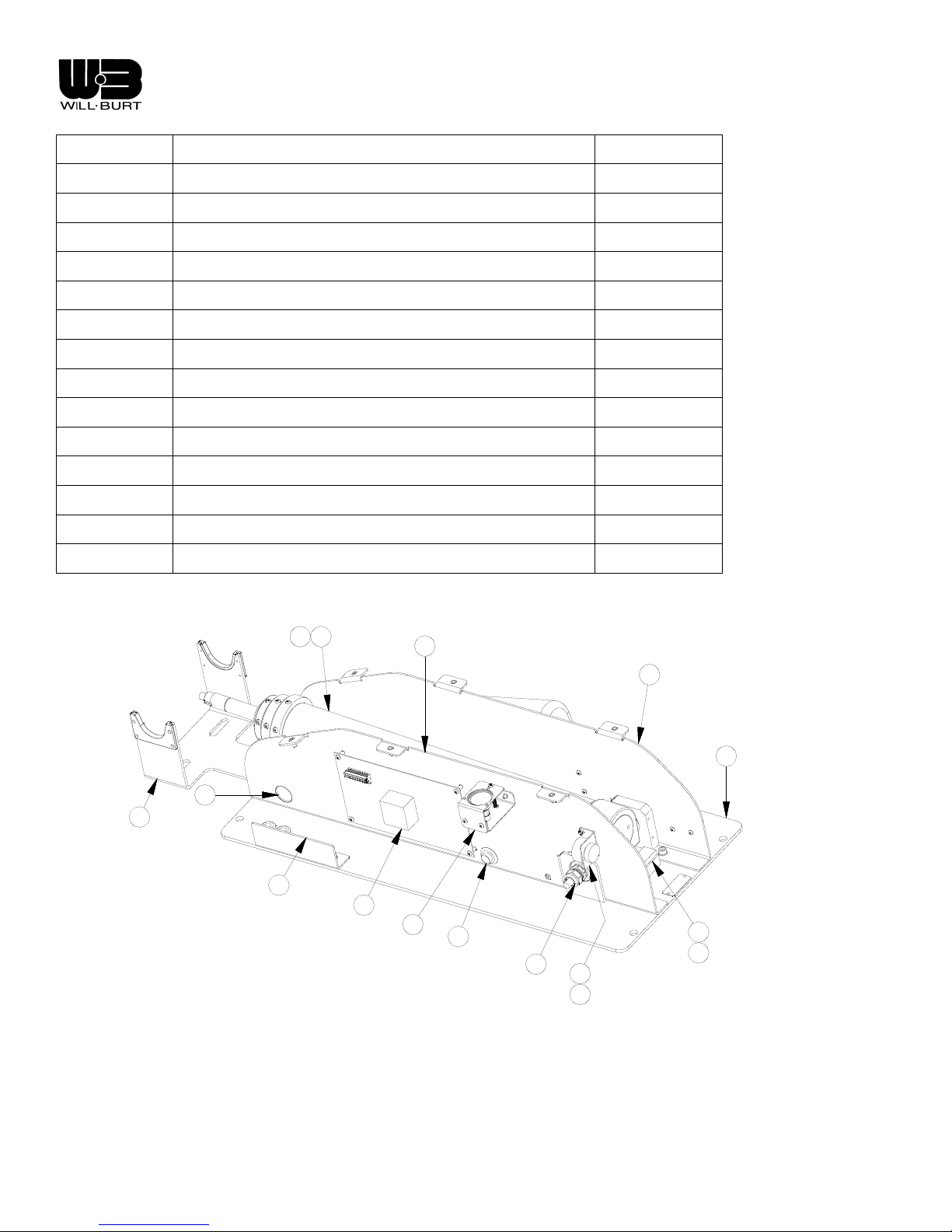
Night Scan Chief
28
29
30
31
32
33
N/A
N/A
N/A
N/A
N/A
N/A
N/A
N/A
N/A
Shim Washer 4122601
External Retaining Ring 3401
Spacer 4121301
Internal Retaining Ring 3783
Pivot Block 4121001
Sleeve Bearing 4120401
Base Cover Left 4143002
Base Cover Right 4141002
Handheld Remote Control 4183601
6
11
22
3
9
2
7
8
1
10
12
21
19
20
14
15
Figure 5-1 Exploded View - Base Left Side
Revision 1 5-2
Page 53
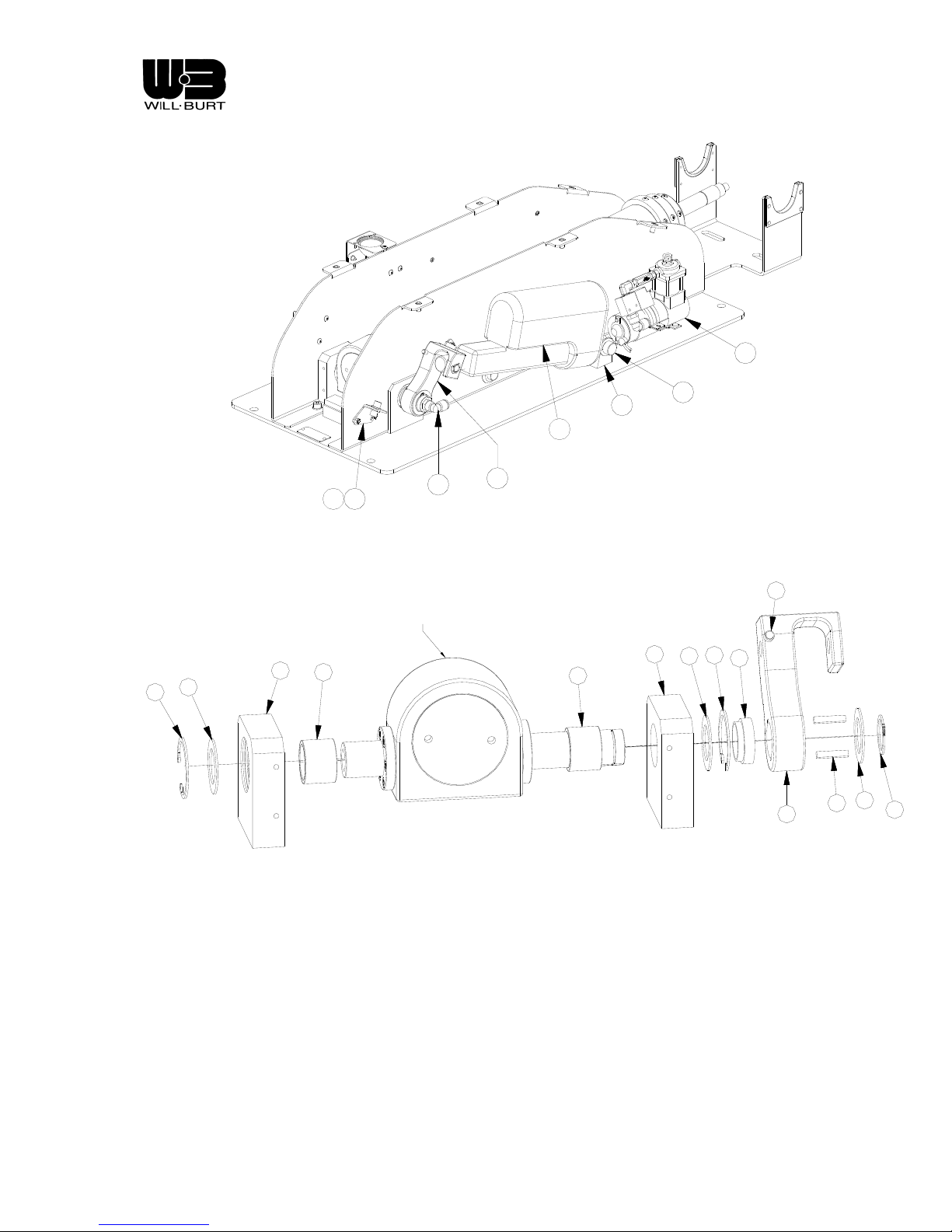
Night Scan Chief
4
17
5
1624
23
18
13
Figure 5-2 Base Right Side
25
MAST BOTTOM
32
32
28
31
33
33
31
28
30
28
26
27
29
Revision 1 5-3
Figure 5-3 Exploded View – Mast Pivot Assembly
Page 54

Night Scan Chief
Table 5-2. Remote Control Positioner Assembly Parts List
Mark No. Description Part Number
1 Remote Control Positioner Frame 4124102
2 Circuit Board, RCP 4118401
3 Pan Bearing Housing 4124302
4 Tilt Coupling 4124801
5 Horizontal Bearing 913435
6 Bearing Retainer 4124202
7 Pan Bearing Spacer 4124401
8 Pan Gear 4124901
9 Pan Flag 4125201
10 Card Guide 913881
11 Terminal Bracket 4125401
12 Shim Washer 4203701
13 Key 4120802
14 Terminal Block 215001
15 Snap Ring 3401
16 Motor Assembly 4205001
17 Pan Bearing 3868
18 Flat Washer 3872
19 Snap Ring 4208001
20 O-Ring, PTFE 3398
21 Tilt Flag 4125101
22 Flag Mounting Ring 4125301
Revision 1 5-4
Page 55
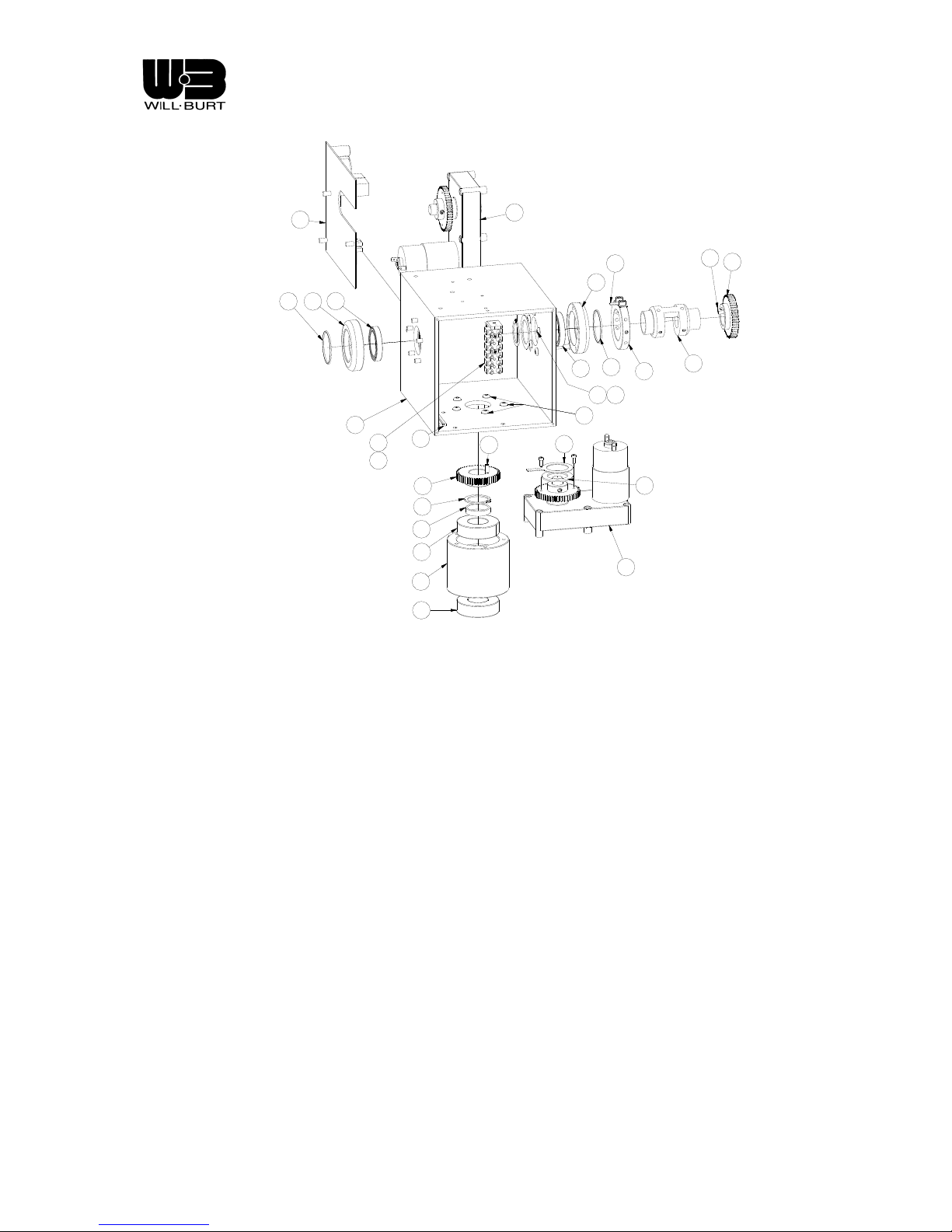
Night Scan Chief
2
5
620
1
10
14
11
8
19
7
17
3
17
16
21
6
20
5
26
13
9
22
15 12
18
16
13
4
Figure 5-4 Exploded View - Remote Control Positioner (RCP)
8
Revision 1 5-5
Page 56

Page 57

Night Scan Chief
CHAPTER 6
REVISIONS
Revision 0, October 2007: Initial Release.
Revision 1, December 2007: Update base schematic Figure 4-8 to correct inclination motor wiring and add
capacitor. Add 2.10 to address capacitor use in 24 vdc multiplex installations.
Revision 1 6-1
Page 58

Page 59

Night Scan Chief
CHAPTER 7
SOFTWARE REVISIONS
7.1 INTRODUCTION
There are several circuit boards in the Chief system. Each has its own mi croco ntroller with associated
software. A person may “query” the software revisions by simultaneously holding down both Remote
Control tilt buttons (up, down). The revision levels can then be viewed as they scroll across the
alphanumeric display. A typical display might be “1:4.3 2:4.2 3:4.2”. This would indicate that board 1
(the base board) has revision 4.3, board 2 (the RCP board) has revision 4.2, and board 3 (a Remote
Control board) has revision 4.2. To date, all software revisions are backward compatible, and require no
hardware changes.
Table 7-1. Software Revision Log
Board
Base 1 4.3 Initial Release to production None
RCP 2 4.2 Initial Release to production None
HHRC 3 4.2 Initial Release to production None
Base 1 4.4 Fix transceiver enable timing to prevent
HHRC 3 4.4 Fix transceiver enable timing to prevent
Base 1 4.5 Fix to SPI timing to prevent intermittent
Board
No.
Revision Comments Compatibility Issues
None
intermittent power up timing problem
None
intermittent power up timing problem
None
analog input read failures
Revision 1 7-1
Page 60

Night Scan Chief
CHAPTER 8
APPENDICES
Revision 1 8-2
Page 61

MATERIAL SAFETY DATA SHEET
The Will-Burt Company Orrville, Ohio 330-682-7015
SECTION A: IDENTIFICATION AND EMERGENCY INFORMATION
Product Name: Mast Lubrication 900600
Chemical Name: Cas Number:
Not Applicable (N/A) N/A
Chemical Family:
Industrial Metalworking Compound
Emergency Telephone Number: Revision Date:
440-543-9845 (Etna) 5/3/00
HMIS RATING: H= 1 F= 1 R= 0 PP= C
SECTION B: HAZARDOUS INGREDIENTS
This Product does not contain any SARA Section 313 reportable compounds.
This product does not contain any carcinogens as defined by OSGA, NTP and IARC at greater
than 0.1%.
SECTION C: PHYSICAL & CHEMICAL CHARACTERISTICS
Boiling Point: Specific Gravity: Vapor Pressure:
Unknown 0.9 Unknown
% Volatile (Vol.): Vapor Density (Air=1): Evap. Rate (N-BA=1):
Unknown Unknown >1
Solubility in Water: Ph (N/A): Reactivity in Water:
Nil N/A Nil
Appearance: Odor:
Blue Liquid Petroleum Odor
Flash Point: Flammable Limits (In Air % by Vol.): Auto Ignition:
>350°F (Upper) Unknown (Lower) Unknown Unknown
Extinguisher Media & Special Fire Fighting Procedures:
Use water, fog, foam dry chemical or CO2. Do not use a direct stream of water. Product may
float and can be re-ignited on the surface of the water. Do not enter confined fire space without
proper protective equipment including a NIOSH approved self-contained breathing apparatu s.
Cool exposed surfaces.
Unusual Fire and Explosion Hazards:
None
FORM No. ENG- 330 - 95 – 03 7/7/00
A 1
Page 62

SECTION D: PHYSICAL HAZARDS
Stability: Conditions to Avoid:
Stable Strong Oxidants
Incompatibility:
Strong Oxidants
Decomposition Products:
Highly dependent on combustion conditions. Mixture of air-borne solid, liquid and gases evolve
upon pyrolysis or combustion of this product. CO
and other organic compounds may be formed
2
upon combustion.
Hazardous Polymerization:
Will not occur
Conditions to Avoid:
STRONG OXIDANTS – HEAT – SPARK AND OPEN FLAMES
SECTION E: HEALTH HAZARDS
Signs and Symptom of Exposure:
Skin: Prolonged and repeated skin contact may cause irritation or skin disorders such
as dermatitis or oil acne. Wash thoroughly with soap and water prior to using
toilet facilities, eating, drinking or smoking.
Eyes: Contact with eyes may cause temporary irritation.
Inhalation: The inhalation of vapors (generated at high temperatures only) or oil mist may
cause a mild irritation of the mucous membrane of the upper respiratory tract.
Ingestion: Considered no more than slightly toxic if swallowed.
Medical Conditions Generally Aggravated by Exposure:
Pre-existing skin and respiratory disorders may be aggravated by exposure.
Oral LD50: Dermal LD50: Inhalation LD50:
N/E N/E N/E
OSHA PEL/TWA OSHA PEL/CEILING ACGIh TLV/TWA ACGh TLV/STEL
5mg/M3 N/E 5mg/M3 10mg/M3
FORM No. ENG- 330 - 95 – 03 7/7/00
Acute Toxicity Data:
Occupational Exposure Limits:
Chronic Health Data:
None
A 2
Page 63

SECTION F: EMERGENCY AND FIRST AID PROCEDURES
Skin contact: Remove contaminated clothing and wash with soap and water. If irritation occurs
get medical attention.
Eye contact: Flush with water for 15 minutes. If irritation occurs get medical attention.
Ingestion: Do not induce vomiting. Get medical attention.
SECTION G: SPECIAL PROTECTION / SPILL AND LEAK PROCEDURES
Ventilation: Local exhaust – required only to capture vapor, mist or fumes.
Mechanical (general): As required to prevent exceeding recommended exposure limits.
Protective gloves: Use chemically resistant gloves to avoid prolonged skin contact.
Eye Protection: Use safety glasses or goggles to prevent eye contact.
Respiratory Protection: As needed to prevent overexposure to mist or fumes. Use NIOSH
approved chemical mist and organic vapor respirators.
Other protective clothing or equipment: Use chemically resistant apron as needed.
SECTION H: ENVIRONMENTAL PROTECTION / SPILL AND LEAK PROCEDURES
Spill or Leak: Recover free product. Add sand, earth or other suitable absorbent to spill area.
Minimize worker contact. Keep from sewers or waterways by diking or
impounding. Advise authorities if product enters waterways or extensive land
areas. Dispose of recovered material and residue in compliance with all federal,
state, and local regulations.
Waste Disposal: Dispose of all waste products in accordance with all applicable federal, state and
local regulations.
Handling and Storage Precautions: Keep container closed when not in use. Do not store
near heat, open flame or strong oxidants.
SECTION I: TRANSPORTATION REQUIREMENTS
DOT Shipping Regulations:
Consider this product to be non-hazardous. No special labeling required by DOT.
SECTION J: OTHER REGULATORY CONTROLS
The ingredients of this product are on the TSCA Inventory.
The information contained herein is based on the data available to us and is believed to be
correct. The Will-Burt Company does not warrant or guarantee their accuracy or reliability and
The Will-Burt Company shall not be liable for any loss or damage arising out of the use thereof.
The information and recommendations are offered for the user’s consideration and examination
and it is the user’s responsibility to satisfy itself that they are suitable and complete for its
particular use.
FORM No. ENG- 330 - 95 – 03 7/7/00
A 3
Page 64

WILL-BURT PRODUCT REGISTRATION
AND EVALUATION
RETURN WITHIN 90 DAYS FROM DATE OF PURCHASE
PLEASE COMPLETE THIS FORM AND RETURN TO WILL-BURT USING THE PREPAID SELFADDRESSED ENVELOPE WHICH HAS BEEN PROVIDED. THANK YOU FOR YOUR
ASSISTANCE.
CUSTOMER NAME: __________________________________ ___DATE: _______________
ADDRESS:
__________________________________________________________________________
CITY / STATE / ZIP: ________________________PHONE No. : _______________________
PRODUCT MODEL No. / NAME / DESCRIPTION:
___________________________________________________________________________
PRODUCT SERIAL No. : ________________DATE OF PURCHASE: ___________________
DEALER NAME (WHERE PURCHASED):
_________________________________________________________________________
INSTALLER NAME:
_________________________________________________________________________
WHERE DID YOU HEAR ABOUT THIS PRODUCT?
_________________________________________________________________
WHY DID YOU PURCHASE THIS PRODUCT?
______________________________________________________________________
WAS THE PRICE OF THIS PRODUCT COMPETITIVE? YES __________ NO __________
WOULD YOU PURCHASE THIS PRODUCT AGAIN? YES __________ NO__________
WOULD YOU RECOMMEND THE PURCHASE OF THIS PRODUCT TO YOUR FRIENDS OR
THEIR ASSOCIATES? YES __________ NO__________
DOES THE PRODUCT SATISFY YOUR NEEDS / REQUIREMENTS? IF NO, EXPLAIN:
_____________________________________________________________________________
_____________________________________________________________________________
_____________________________________________________________________________
_____________________________________________________________________________
DO YOU BELIEVE ANY FEATURE COULD BE IMPROVED TO ENHANCE THE
PERFORMANCE OF THE PRODUCT? IF YES, EXPLAIN:
_____________________________________________________________________________
_____________________________________________________________________________
_____________________________________________________________________________
_____________________________________________________________________________
_____________________________________________________________________________
PLEASE CONTINUE ON REVERSE SIDE.
FORM No. ENG- 330 - 95 – 03 7/7/00
A 4
Page 65

ARE SATISFIED WITH THE APPEARANCE OF THE PRODUCT? YES _______NO_________
IF NO EXPLAIN :
_____________________________________________________________________________
_____________________________________________________________________________
_____________________________________________________________________________
_____________________________________________________________________________
RATE THE INSTALLATION / OPERATION / SERVICE INSTRUCTIONS.
GOOD ____ FAIR ____ POOR_____
DO YOU HAVE ANY SUGGESTIONS FOR IMPROVING THE INSTALLATION / OPERATION /
SERVICE INSTRUCTIONS? IF YES, EXPLAIN:
_____________________________________________________________________________
_____________________________________________________________________________
_____________________________________________________________________________
_____________________________________________________________________________
_____________________________________________________________________________
ADDITIONAL COMMENTS:
_____________________________________________________________________________
_____________________________________________________________________________
_____________________________________________________________________________
_____________________________________________________________________________
_____________________________________________________________________________
_____________________________________________________________________________
ALL SUGGESTIONS PRESENTED TO WILL-BURT COMPANY ON THIS FORM RELATED TO THE WILLBURT COMPANY PROPRIETARY PRODUCT LINES WILL BE REVIEWED. HOWEVER, THE
EVALUATION OF ANY PARTICULAR SUGGESTION NEITHER IMPLIES NOR GUARANTEES
IMPLEMENTATION OF THE SUGGESTED CHANGE. ALL REVISIONS, MODIFICATIONS, AND / OR
IMPROVEMENTS MADE TO THE WILL-BURT PROPRIETARY PRODUCTS AS A RESULT OF
SUGGESTIONS MADE ON THIS SHALL BE THE SOLE AND EXCLUSIVE PROPERTY OF THE WILLBURT COMPANY, AND NO COMPENSATION OR CONSIDERATION OF ANY KIND WILL BE PAID FOR
SUCH RECOMMENDATIONS.
______________________________________________________________________________________
DO NOT WRITE IN THE SPACE BELOW - RESERVED FOR FACTORY USE ONLY.
_____________________________________________________________________________
__________________________________
______________________________________________________________________________________
______________________________________________________________________________________
______________________________________________________________________________________
_______________________________________________________________
________________________________________________
____________________
_____________________________________________________________________________
_____________
______________________________________________________________________________________
_____________________________________________________________________________________
______________________________________________________________________________________
_____________________________________
__________________________________________
______________________________________________________________________________________
______________________________________________________________________________________
_______________________________________________________________________
____________________________________________
_______________________________________
FORM No. ENG- 330 - 95 – 03 7/7/00
A 5
 Loading...