

INSTRUCTIONS
GEBRUIKSAANWIJZING
MOUNTING
Remove the 4 screws from the corners of the front panel and take
the compressor out of the case. Mount the case in the desired
position with minimum 4 screws M6.
Mount the compressor back into the case and close the front
panel. Leave ventilation openings unobstructed.
DC POWER SUPPLY
A power supply cable (minimum 3 x 2,5 mm²) has to be used to
avoid voltage drop and should be connected to the 4-pin plug as
following :
1 = “+” 2 = “--” = earth link
AIR CONNECTIONS
The compressor is equipped with 2 quick connect fittings to be
used with 3/8” air hose. To lead away air, moisture and water, it
is recommended that the “AIR EXHAUST” connector is fitted with
an air hose, running to the outside of the vehicle.
OPERATION
Hand-operated (without using a controller) :
Set the selector switch “REMOTE/MANUAL” at the bottom of the
compressor to "MANUAL". Push the toggle switch of the
compressor into the position “MAST UP”. The switch should be
kept in this “MAST UP” position till the mast has been fully extended
or has reached the desired height. The moment the toggle switch
will be released, the switch will jump automatically into the position
“HOLD” and the compressor will stop running (= deadman function).
To retract the mast, push the toggle switch into the position
“MAST DOWN/OFF”.
Remote controlled :
Set the selector switch “REMOTE/MANUAL” at the bottom of the
compressor to “REMOTE”. Connect the 7 pin-plug of the controller
into the socket on the front panel of the compressor. Push the
toggle switch of the controller into the position “UP”. The switch
should be kept in this “UP” position till the mast has been fully
extended or has reached the desired height. The moment the
toggle switch will be released, the switch will jump automatically
into the position “HOLD” and the compressor will stop running
(= deadman function). To retract the mast, push the toggle switch
into the position “DOWN/OFF”.
ADJUSTMENT OF PRESSURE SWITCH
The maximum operating pressure is 25 psi (1,8 bar).
The pressure switch is factory-set at approximately 15 psi (1 bar).
The pressure switch can be adjusted with a screw driver through
the hole “PRESSURE ADJUSTMENT” on the front panel.
Turn the screw driver anti-clockwise, to have less pressure or
turn it clockwise for more pressure. You can read the pressure
to the mast on the manometer.
MAINTENANCE
No items require regular attention. For good general maintenance,
keep unit clean and check regularly connections. Always disconnect
the power supply cable before taking the compressor out of the
case.
MONTAGE
Verwijder de 4 schroeven van de hoeken van het frontpaneel en
neem de compressor uit zijn behuizing. Installeer de behuizing in
de gewenste positie met minimaal 4 schroeven M6.
Plaats de compressor terug in de behuizing en sluit het frontpaneel.
Houd de ventilatieopeningen vrij.
DC ELEKTRISCHE AANSLUITING
Gebruik een voedingskabel van minimum 3 x 2,5 mm² om spanningsval
te vermijden en sluit als volgt aan op de 4-polige stekker :
1 = “+” 2 = “--” = aarding
LUCHTAANSLUITINGEN
De compressor is uitgerust met 2 snelkoppelingen, te gebruiken
met een 3/8” luchtslang. Om eventueel lucht, condens en water af
te voeren, is het aanbevolen om de “AIR EXHAUST”-aansluiting
te verbinden met een luchtslang, die tot buiten het voertuig loopt.
WERKING
Manueel (zonder gebruik van afstandsbediening)
Stel de keuzeschakelaar “REMOTE/MANUAL” onderaan de
compressor in op “MANUAL”. Duw de tuimelschakelaar op stand
"MAST UP". De schakelaar moet ingeschakeld blijven in deze
“MAST UP” stand totdat de mast volledig is uitgeschoven of de
gewenste hoogte heeft bereikt. Vanaf het moment dat de
tuimelschakelaar wordt losgelaten, springt de schakelaar
automatisch over op stand “HOLD”, waarbij de compressor stopt
(= dodemansfunctie). Om de mast in te schuiven, duw de
tuimelschakelaar op stand “MAST DOWN/OFF”.
Met afstandsbediening :
Stel de keuzeschakelaar “REMOTE/MANUAL” onderaan de
compressor in op “REMOTE”. Schroef de 7-polige stekker van
de afstandsbediening in het stopcontact op het voorpaneel van de
compressor. Duw de tuimelschakelaar op stand "UP". De
schakelaar moet ingeschakeld blijven in deze “UP” stand totdat de
mast volledig is uitgeschoven of de gewenste hoogte heeft bereikt.
Vanaf het moment dat de tuimelschakelaar wordt losgelaten,
springt de schakelaar automatisch over op stand “HOLD”, waarbij
de compressor stopt (= dodemansfunctie). Om de mast in te
schuiven, duw de tuimelschakelaar op stand “DOWN/OFF”.
AFSTELLING VAN DRUKSCHAKELAAR
De maximum druk is 25 psi (1,8 bar). In de fabriek wordt de
schakelaar op ca. 15 psi (1 bar) afgesteld.
De druk kan met een schroevendraaier geregeld worden door de
opening “PRESSURE ADJUSTMENT” op het voorpaneel van de
compressor. Draai de schroevendraaier in tegenwijzerzin voor
minder druk, in wijzerzin voor meer druk. De druk naar de mast
kan op de manometer afgelezen worden.
ONDERHOUD
De onderdelen vereisen geen regelmatig onderhoud. Voor een
goed algemeen onderhoud, houd de compressor zuiver en
controleer regelmatig de aansluitingen. Ontkoppel steeds de
batterijleidingen alvorens de compressor uit de behuizing te nemen.
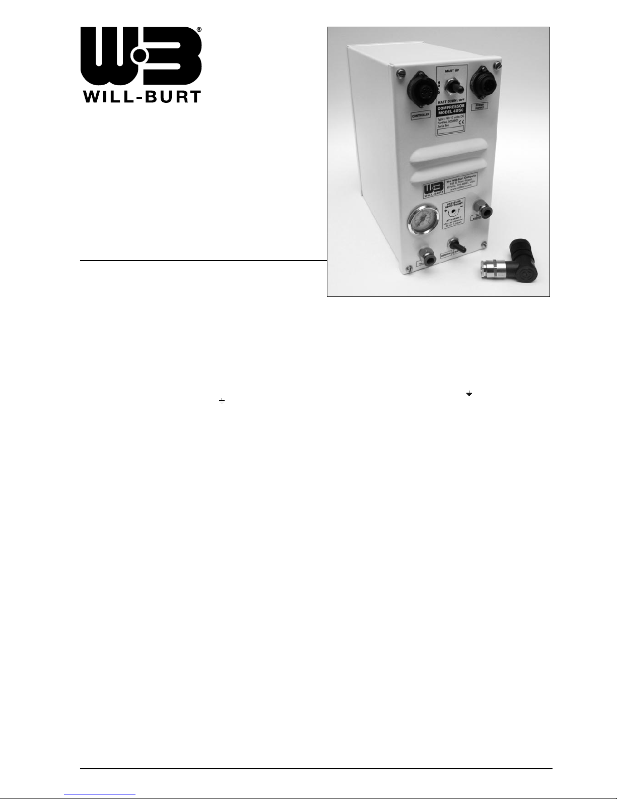
Type : NO 12 Volt DC + deadman function
Type : Part No. 5059801
Type : NO 24 Volt DC + deadman function
Type : Part No. 5059802
COMPRESSOR MODEL 40/50
CONTROLLER
Type : NO 12 Volt DC with toggle switch +
Type : deadman function Part No. 5057001
Type : NO 24 Volt DC with toggle switch +
Type : deadman function Part No. 5057002
ELECTRICAL WIRING CONTROLLER - NO VALVE
ELEKTRISCH SCHEMA VAN AFSTANDSBEDIENING - NO VENTIEL
DIAGRAMME ELECTRIQUE DE LA COMMANDE A DISTANCE - VALVE NO
ELEKTRISCHES DIAGRAMM DER FERNBEDIENUNG - NO VENTIL
SPECIFICATIONS
SPECIFICATIES
SPECIFICATIONS
SPEZIFIKATIONEN
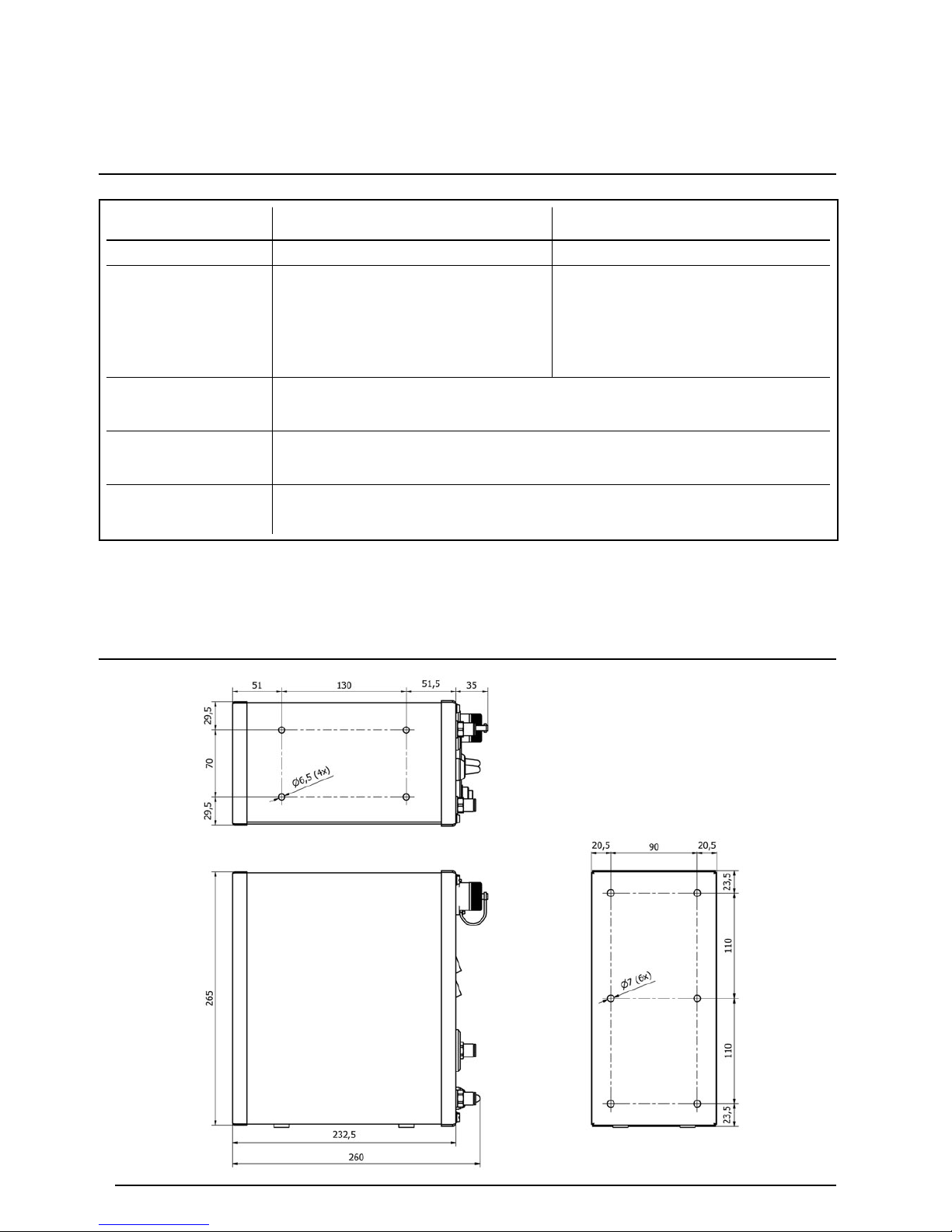
INSTALLATION DRAWING
INSTALLATIETEKENING
DESSIN D’INSTALLATION
INSTALLATIONSZEICHNUNG
TYPE
Part No.
Current at
15 psi (1 bar) / 25 psi (1,8 bar)
Stroom bij
15 psi (1 bar) / 25 psi (1,8 bar)
Courant avec
15 psi (1 bar) / 25 psi (1,8 bar)
Strom bei
15 psi (1 bar) / 25 psi (1,8 bar)
Output
Opbrengst
Rendement
Luftliefermenge
Weight
Gewicht
Poids
Gewicht
Min./Max. temperature
Min./Max. temperatuur
Min./Max. température
Min./Max. Temperatur
12 amps / 13 amps
12V Compressor NO / 12V Compressor NO
12V Compresseur NO / 12V Kompressor NO
5059801
8 kg
-20°C / +50°C
40 l/min. at 15 psi
8 amps / 9 amps
24V Compressor NO / 24V Compressor NO
24V Compresseur NO / 24V Kompressor NO
5059802
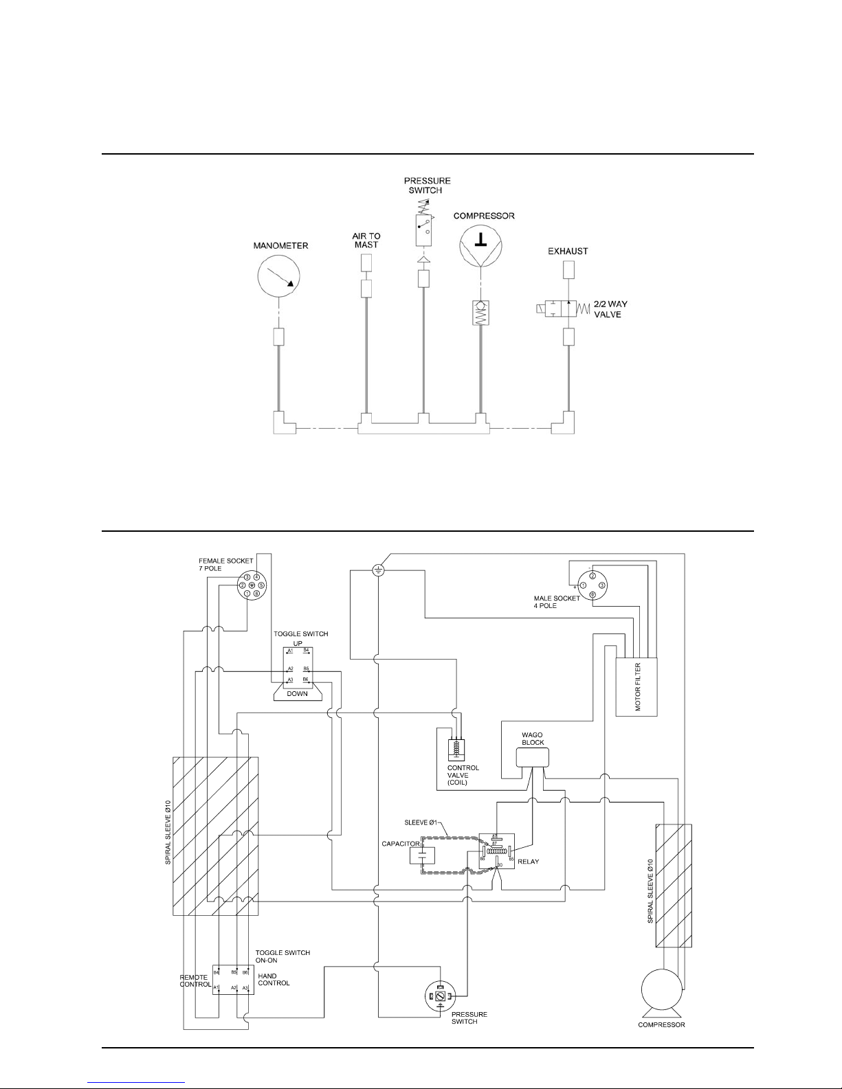
PNEUMATIC DIAGRAM
PNEUMATISCH SCHEMA
DIAGRAMME PNEUMATIQUE
PNEUMATISCHES DIAGRAMM
ELECTRICAL DIAGRAM
ELEKTRISCH SCHEMA
DIAGRAMME ELECTRIQUE
ELEKTRISCHES DIAGRAMM

EXPLODED VIEW
ZICHT VAN DE ONDERDELEN
VUE ECLATEE
EXPLOSIONSZEICHNUNG DER TEILEN

SPARE PARTS LIST
ONDERDELENLIJST
LISTE DES COMPOSANTS
TEILLISTE
PNEUMATIC DIAGRAM
PNEUMATISCH SCHEMA
DIAGRAMME PNEUMATIQUE
PNEUMATISCHES DIAGRAMM
ELECTRICAL DIAGRAM
ELEKTRISCH SCHEMA
DIAGRAMME ELECTRIQUE
ELEKTRISCHES DIAGRAMM

ELECTRICAL WIRING CONTROLLER - NO VALVE
ELEKTRISCH SCHEMA VAN AFSTANDSBEDIENING - NO VENTIEL
DIAGRAMME ELECTRIQUE DE LA COMMANDE A DISTANCE - VALVE NO
ELEKTRISCHES DIAGRAMM DER FERNBEDIENUNG - NO VENTIL
CONTROLLER 12V DC with toggle switch +
deadman function Part No. 5057001 (NO)
CONTROLLER 24V DC with toggle switch +
deadman function Part No. 5057002 (NO)

MODE D'EMPLOI
GEBRAUCHSANWEISUNG
MONTAGE
Dévissez les 4 vis qui se trouvent dans les coins du panneau
avant et enlevez le compresseur du boîtier. Positionnez le boîtier
dans la position souhaitée avec minimum 4 vis M6. Repositionnez
le compresseur dans le boîtier et refixez le panneau avant.
Laissez les ouvertures de ventilation libres.
CC RACCORDEMENT ELECTRIQUE
Il faut utiliser un câble d’alimentation (minimum 3 x 2,5 mm²) pour
éviter une chute de tension et il faut le brancher sur la fiche à 4
conducteurs comme suit :
1 = “+” 2 = “--” = mise à la terre
CONNEXIONS D’AIR
Le compresseur est fourni de 2 raccords rapides à utiliser avec un
tuyau d’air de 3/8”. Pour faire échapper l’air, la condensation et
l’eau, il est recommandé que le connecteur “AIR EXHAUST” soit
équipé d’un tuyau d’air qui l’évacue vers l’extérieur du véhicule.
OPERATION
Manuellement (sans l’aide d’une commande à distance)
Réglez l’interrupteur “REMOTE/MANUAL” en bas du compresseur
sur “MANUAL”. Poussez l’interrupteur à bascule dans la position
“MAST UP”. L’interrupteur à bascule doit rester dans cette position
“MAST UP” jusque le mât a été déployé complètement ou a
atteint la hauteur désirée. Au moment où l'interrupteur à bascule
est lâché, l’interrupteur va sauter automatiquement en position
“HOLD” et le compresseur s'arrête (= fonction homme-mort ).
Pour rétracter le mât, poussez l’interrupteur à bascule dans la
position “MAST DOWN/OFF”.
Commande à distance :
Réglez l’interrupteur “REMOTE/MANUAL” en bas du compresseur
sur “REMOTE”. Vissez la prise à 7 conducteurs de la commande
à distance dans la prise sur le panneau avant du compresseur.
Poussez l’interrupteur à bascule dans la position “UP”.
L’interrupteur à bascule doit rester dans la position “UP” jusque le
mât a été déployé complètement ou a atteint la hauteur désirée.
Au moment où l'interrupteur à bascule est lâché,
l’interrupteur va sauter automatiquement en position “HOLD” et le
compresseur s'arrête (= fonction homme-mort ). Pour rétracter le
mât, poussez l’interrupteur à bascule dans la position “DOWN/OFF”.
REGLAGE DU PRESSOSTAT
La pression maximale est 25 psi (1,8 bar). En usine, le pressostat
est réglé à +/- 15 psi (1 bar).
Le pressostat peut être réglé avec un tournevis par le trou
“PRESSURE ADJUSTMENT” sur le panneau avant. Tournez le
tournevis dans le sens antihoraire, pour avoir moins pression ou
tournez dans le sens horaire pour avoir plus de pression.
La pression est lisible sur le manomètre sur le panneau avant du
compresseur.
ENTRETIEN
Le compresseur ne nécessite pas un entretien régulier.
Cependant il faut tenir le compresseur propre et contrôler
régulièrement les raccordements. Découplez toujours les câbles
de la batterie avant d’enlever le compresseur du boîtier.
EINBAU
Die 4 Schrauben an den Ecken der Frontplatte lösen und den
Kompressor aus seinem Gehäuse ziehen. Das Gehäuse mit
mindestens 4 Schrauben M6 befestigen. Setzen Sie den
Kompressor wieder ins Gehäuse und verschrauben die
Frontplatte. Bitte beachten Sie, dass bei der Montage die
Luftschlitze an der Frontplatte frei bleiben.
DC STROMVERSORGUNG
Ein Stromkabel (minimum 3 x 2,5 mm²) muss verwendet werden
um Spannungsabfall zu vermeiden und sollte an dem 4-poligen
Stecker angeschlossen werden wie folgt :
1 = “+” 2 = “--” = Erdung
LUFTANSCHLÜSSE
Der Kompressor ist mit zwei Schnellkupplungen für einen 3/8“
Druckluftschlauch ausgestattet. Um Luft, Feuchtigkeit und Wasser
abzulassen wird empfohlen, dass der "AIR EXHAUST"
Lufablassanschluss mit einem Luftschlauch verbunden wird, der
aus dem Fahrzeug geführt wird.
EINSATZ
Manuell (ohne Verwendung einer Fernbedienung)
Schalter “REMOTE/MANUAL” auf “MANUAL” bringen, der sich auf
der Unterseite des Kompressors befindet. Drücken Sie den
Kippschalter in die Position "MAST UP". Der Schalter muss in
dieser "MAST UP" Position gehalten werden, bis der Mast komplett
ausgefahren ist oder die gewünschte Höhe erreicht hat. Wenn der
Kippschalter losgelassen wird, springt der Schalter automatisch
in die Position "HOLD" und stoppt den Kompressor
(= Totmannfunktion). Um den Mast einzufahren, drücken Sie den
Kippschalter in die Position "MAST DOWN/OFF".
Fernbedienung :
Schalter “REMOTE/MANUAL” auf “REMOTE” bringen, der sich auf
der Unterseite des Kompressors befindet. Stecken Sie den
7-poligen Stecker der Kabelfernbedienung in die Steckdose an der
Frontplatte des Kompressors. Drücken Sie den Kippschalter der
Fernbedienung in die Position "UP". Der Schalter muss in dieser
"UP" Position gehalten werden, bis der Mast komplett ausgefahren
ist oder die gewünschte Höhe erreicht hat. Wenn der Kippschalter
losgelassen wird, springt der Schalter automatisch in die Position
"HOLD" und stoppt den Kompressor (= Totmannfunktion). Um den
Mast einzufahren, drücken Sie den Kippschalter in die Position
"DOWN/OFF".
EINSTELLUNG DES DRUCKSCHALTERS
Der maximale Betriebsdruck ist 25 psi (1,8 bar). Der vom Werk
voreingestellte Betriebsdruck liegt bei ca. 15 psi (1 bar).
Der Druckschalter kann mit einem Schraubendreher durch die
Aussparung "PRESSURE ADJUSTMENT" auf der Vorderseite
justiert werden. Drehen des Schraubendrehers gegen den
Uhrzeigersinn verringert den Druck, Drehen im Uhrzeigersinn
vergrößert ihn. Sie können den Druck auf den Mast auf dem
Manometer ablesen.
WARTUNG
Die Kompressoreinheit benötigt keine regelmässige Wartung.
Es reicht, die Einheit sauber zu halten und regelmässig die
Verbindungen zu überprüfen. Achtung ! Immer die Batterieleitungen
abklemmen, bevor der Kompressor aus seinem Gehäuse
genommen wird.
PP 1783 MM 24/10/14
When ordering Spare Parts or in event of a claim under
guarantee, please inform The Will-Burt Company :
1. Serial No. of equipment 2. Date of supply
3. Name and address of supplier
Bij bestelling van reserveonderdelen of in geval van een klacht onder
waarborg, gelieve The Will-Burt Company te informeren:
1. Serienummer van uitrusting 2. Datum van levering
3. Naam en adres van leverancier
Pour commander les pieces de rechange ou en cas d'une réclamation
sous garantie, veuillez informer The Will-Burt Company:
1. Numéro de série de l'équipement 2. Date de livraison
3. Nom et adresse du fournisseur
Bei Bestellung von Ersatzteilen oder im Falle eine Reklamation
unter Garantie, bitte informieren Sie The Will-Burt Company:
1. Serienummer des Materials 2. Lieferdatum
3. Name und Adresse des Lieferanten
All details given in this publication are approximate and may be subject to change without notice. / Alle gegevens in deze uitgave zijn benaderend en
kunnen zonder voorafgaande verwittiging gewijzigd worden. / Les détails donnés dans cette notice sont approximatifs et peuvent être modifiés sans
avis. / Alle Angaben in dieser Broschüre sind Ungefährwerte und sie können zu jeder Zeit ohne vorherige Information geändert werden.
The Will-Burt Company
, 169 S. Main Street, Orrville, OH 44667, USA
Tel : +1-330-682-7015 - Fax : +1-330-684-1190 - E-mail : contact_us@willburt.com - Website : www.willburt.com
 Loading...