

CONTROLLER
Type : NO 24 Volt DC with toggle switch +
Type : deadman function Part No. 5057002
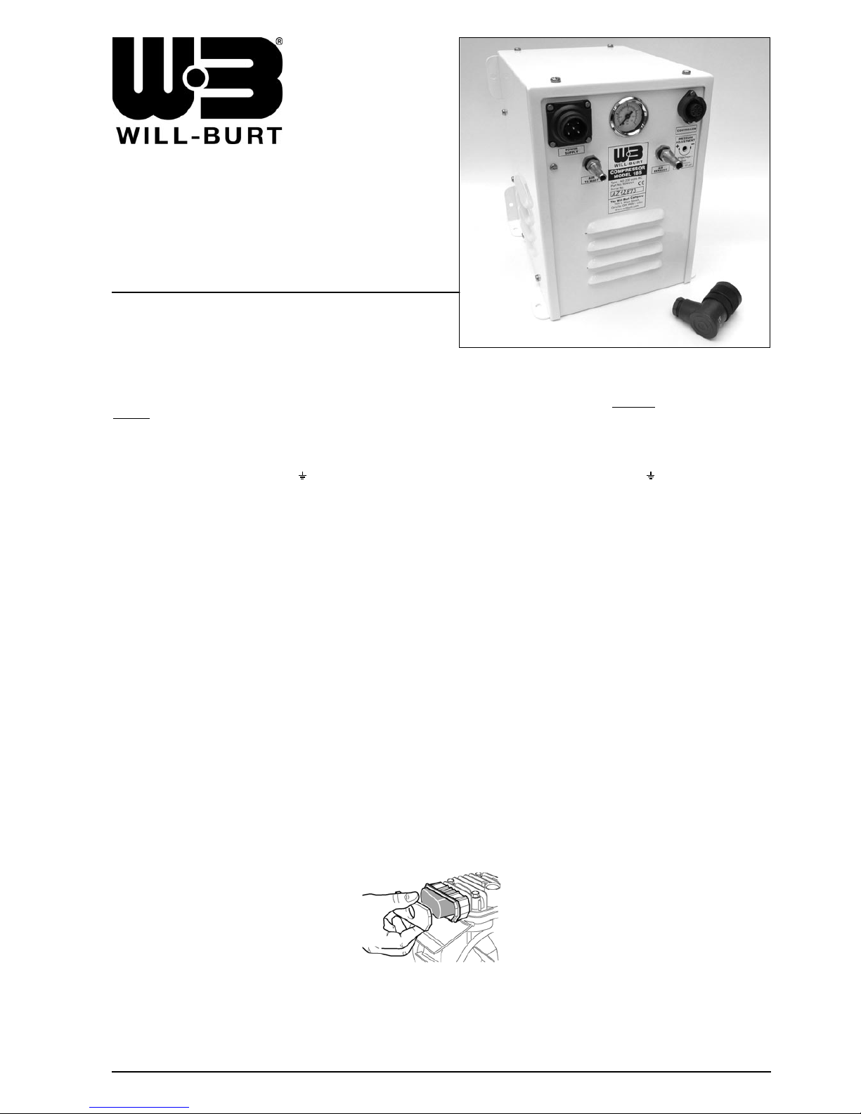
COMPRESSOR MODEL 185
Type : NO 230 Volt AC Part No. 5044201/BF
INSTRUCTIONS
GEBRUIKSAANWIJZING
MOUNTING
Mount the compressor always inside a vehicle, shelter or container.
Mark the fixing points and drill holes of Ø 7 mm. Fit the compressor
with minimum 4 screws M6. Mount the compressor always in
vertical position. Leave ventilation openings unobstructed.
AC POWER SUPPLY
Connect the power supply cable (minimum 3 x 1,5 mm²) of the
mains or the generator to the 5-pin plug :
1 = "L" 2 = "N" = earth link
AIR CONNECTIONS
The compressor is equipped with 2 barb fittings. One is for an
8 mm and the other is for a 10 mm air hose. They may be
unscrewed with a tubular spanner of 14 mm and are interchangeable
according to the diameter of the air hose which is used to connect
the compressor to the mast. To lead away air, moisture and
water, it is recommended that the “AIR EXHAUST” connector is
fitted with an air hose, running to the outside of the vehicle.
OPERATION
Connect the controller to the compressor by plugging in
the 7-pin plug into the socket on the front panel of the
compressor.
Push the toggle switch into position “UP”. The switch should be
kept in “UP” position till the mast has been fully extended or has
reached the desired height. The moment the toggle switch will be
released, the switch will jump automatically into position “HOLD”
and the compressor will stop running (= deadman function).
To retract the mast, push the toggle switch into position
“DOWN/OFF”.
ADJUSTMENT OF PRESSURE SWITCH
The maximum operating pressure is 58 psi (4 bar).
The pressure switch is factory-set at approximately 35 psi (2,4 bar).
The pressure switch can be adjusted with a screw driver through
the hole “PRESSURE ADJUSTMENT” on the front panel.
Turn the screw driver anti-clockwise, to have less pressure or
turn it clockwise for more pressure. You can read the pressure
to the mast on the manometer.
MAINTENANCE
Before performing any maintenance
operation, make sure the power is
disconnected !
1. For good general maintenance, keep the unit
clean and check regularly connections.
2. The compressor is oil-free and does not require
any lubricant.
3. Cleaning the suction filter :
- Remove the compressor casing, then remove
the filter cover and take out the filtering component.
- Rinse the filtering component with water and soap
and make sure that it is totally dry before replacing it again.
Do not operate the compressor without the suction filter
fitted as foreign bodies or dust could seriously damage the
inside components !
MONTAGE
Plaats de compressor altijd in een voertuig, shelter of container.
Duid de bevestigingspunten aan en boor gaten van Ø 7 mm.
Monteer de compressor altijd in verticale positie met minimaal 4
schroeven M6. Houd de ventilatieopeningen vrij.
AC ELEKTRISCHE AANSLUITING
Sluit de voedingskabel (minimum 3 x 1,5 mm²) van het lichtnet of de
aggregaat aan op de 5-polige stekker :
1 = "L" 2 = "N" = aarding
LUCHTAANSLUITINGEN
De compressor is uitgerust met 2 gekartelde luchtaansluitingen. De ene
is geschikt voor een 8 mm en de andere voor een 10 mm luchtslang.
De luchtslangaansluitingen kunnen losgeschroefd worden met een
buissleutel van 14 mm en kunnen, overeenkomstig de diameter van
de slang die gebruikt wordt om de compressor aan de mast aan te
sluiten, onderling verwisseld worden. Om lucht, condens en water af
te voeren, is het aanbevolen om de “AIR EXHAUST”- aansluiting te
verbinden met een luchtslang, die tot buiten het voertuig loopt.
WERKING
Sluit de afstandsbediening aan op de compressor door het
inpluggen van de 7-polige stekker in het stopcontact op het
voorpaneel van de compressor.
Duw de tuimelschakelaar in stand “UP”. De schakelaar moet
ingedrukt blijven in “UP” stand totdat de mast volledig is
uitgeschoven of de gewenste hoogte heeft bereikt. Vanaf het
moment dat de tuimelschakelaar losgelaten wordt, springt de
schakelaar automatisch over op stand “HOLD”, waarbij de
compressor stopt (= dodeman functie).
Om de mast in te schuiven, duw de tuimelschakelaar op stand
“DOWN/OFF”.
AFSTELLING DRUKSCHAKELAAR
De maximum druk is 58 psi (4 bar). In de fabriek wordt de
schakelaar op ca. 35 psi (2,4 bar) afgesteld.
De druk kan met een schroevendraaier geregeld worden via de
opening “PRESSURE ADJUSTMENT” op het voorpaneel van de
compressor. Draai de schroevendraaier in tegenwijzerzin voor
minder druk, in wijzerzin voor meer druk. De druk naar de mast
kan op de manometer afgelezen worden.
ONDERHOUD
Alvorens om het even welke onderhoudshandeling uit te voeren, zorg ervoor dat de
voeding ontkoppeld is !
1. Voor een goed algemeen onderhoud, dient U de
compressor zuiver te houden en regelmatig de
aansluitingen te controleren.
2. De compressor is olievrij en vereist geen smeermiddel.
3. Het schoonmaken van de aanzuigfilter :
- Verwijder de behuizing van de compressor, verwijder vervolgens
het deksel van de filter en neem het filtrerend element uit.
- Spoel het filtrerend element met water en zeep en zorg dat het
filtrerend element volledig droog is vooraleer het terug te plaatsen.
Gebruik de compressor nooit zonder aanzuigfilter.
De ingang van vreemde lichamen of stof kan ernstige schade
aan de interne componenten berokkenen !
SPECIFICATIONS
SPECIFICATIES
SPECIFICATIONS
SPEZIFIKATIONEN
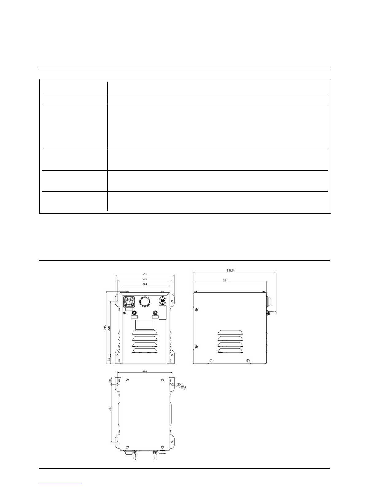
INSTALLATION DRAWING
INSTALLATIE TEKENING
DESSIN D’INSTALLATION
INSTALLATIONSZEICHNUNG
TYPE
Part No.
Current at
35 psi (2,4 bar) / 58 psi (4 bar)
Stroom bij
35 psi (2,4 bar) / 58 psi (4 bar)
Courant avec
35 psi (2,4 bar) / 58 psi (4 bar)
Strom bei
35 psi (2,4 bar) / 58 psi (4 bar)
Output
Opbrengst
Rendement
Luftliefermenge
Weight
Gewicht
Poids
Gewicht
Min./Max. temperature
Min./Max. temperatuur
Min./Max. température
Min./Max. Temperatur
5,1 amps / 5,5 amps
230V Compressor NO / 230V Compressor NO
230V Compresseur NO / 230V Kompressor NO
5044201/BF
16,5 kg
-20°C / +50°C
185 l/min.
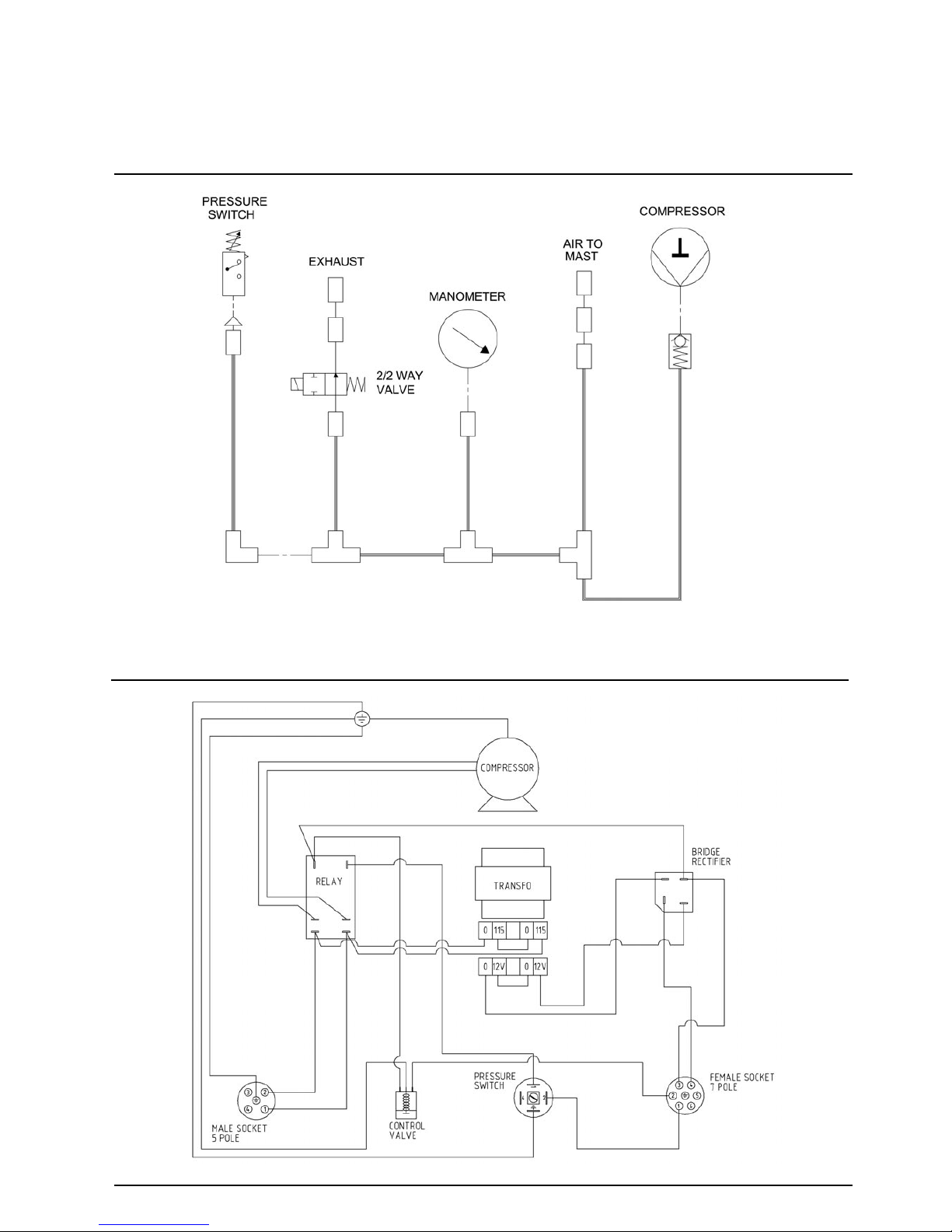
PNEUMATIC DIAGRAM
PNEUMATISCH SCHEMA
DIAGRAMME PNEUMATIQUE
PNEUMATISCHES DIAGRAMM
ELECTRICAL DIAGRAM
ELEKTRISCH SCHEMA
DIAGRAMME ELECTRIQUE
ELEKTRISCHES DIAGRAMM

EXPLODED VIEW
ZICHT VAN DE ONDERDELEN
VUE ECLATEE
EXPLOSIONSZEICHNUNG DER TEILEN
SPARE PARTS LIST
ONDERDELENLIJST
LISTE DES COMPOSANTS
TEILLISTE

SPARE PARTS LIST
ONDERDELENLIJST
LISTE DES COMPOSANTS
TEILLISTE

PNEUMATIC DIAGRAM
PNEUMATISCH SCHEMA
DIAGRAMME PNEUMATIQUE
PNEUMATISCHES DIAGRAMM
ELECTRICAL WIRING CONTROLLER - NO VALVE
ELEKTRISCH SCHEMA VAN AFSTANDSBEDIENING - NO VENTIEL
DIAGRAMME ELECTRIQUE DE LA COMMANDE A DISTANCE - VALVE NO
ELEKTRISCHES DIAGRAMM DER FERNBEDIENUNG - NO VENTIL
CONTROLLER 24V DC with toggle switch + deadman function :
Part No. 5057002 (NO)
ELECTRICAL DIAGRAM
ELEKTRISCH SCHEMA
DIAGRAMME ELECTRIQUE
ELEKTRISCHES DIAGRAMM


MODE D'EMPLOI
GEBRAUCHSANWEISUNG
When ordering Spare Parts or in event of a claim under
guarantee, please inform The Will-Burt Company :
1. Serial No. of equipment. 2. Date of supply.
3. Name and address of supplier.
Bij bestelling van reserveonderdelen of in geval van een klacht onder
waarborg, gelieve The Will-Burt Company te informeren:
1. Serienummer van uitrusting. 2. Datum van levering.
3. Naam en adres van leverancier.
Pour commander les pieces de rechange ou en cas d'une réclamation
sous garantie, veuillez informer The Will-Burt Company:
1. Numéro de série de l'équipement. 2. Date de livraison.
3. Nom et adresse du fournisseur.
Bei Bestellung von Ersatzteilen oder im Falle eine Reklamation
unter Garantie, bitte informieren Sie The Will-Burt Company:
1. Serienummer des Materials. 2. Lieferdatum.
3. Name und Adresse des Lieferanten.
All details given in this publication are approximate and may be subject to change without notice / Alle gegevens in deze uitgave zijn benaderend en
kunnen zonder voorafgaande verwittiging gewijzigd worden / Les détails donnés dans cette notice sont approximatifs et peuvent être modifiés sans
avis / Alle Angaben in dieser Broschüre sind Ungefährwerte und sie können zu jeder Zeit ohne vorherige Information geändert werden.
The Will-Burt Company
, 169 S. Main Street, Orrville, OH 44667, USA
Tel : +1-330-682-7015 - Fax : +1-330-684-1190 - E-mail : contact_us@willburt.com - Website : www.willburt.com
MONTAGE
Positionnez le compresseur toujours à l'intérieur d’un véhicule,
shelter ou container. Indiquez la position des boulons et percez
des trous de Ø 7 mm. Positionnez le compresseur toujours en
position verticale
avec minimum 4 vis M6. Laissez les ouvertures
de ventilation libres.
CA RACCORDEMENT ELECTRIQUE
Branchez le câble d’alimentation (minimum 3 x 1,5 mm²) du réseau
électrique ou du groupe électrogène sur la fiche à 5 broches :
1 = "L" 2 = "N" = mise à la terre
CONNEXIONS D’AIR
Le compresseur est fourni de 2 raccords cannelés. Un pour un
tuyau d’air de 8 mm et l’autre pour un tuyau d’air de 10 mm.
Ils peuvent être dévissés avec un clef tubulaire de 14 mm.
Ils sont aussi interchangeables, selon le diamètre du tuyau d’air
qui est branché du compresseur au mât. Pour faire échapper l’air,
la condensation et l’eau, il est recommandé que le connecteur
“AIR EXHAUST” soit équipé d’un tuyau d’air qui l’évacue vers
l’extérieur du véhicule.
OPERATION
Branchez la commande à distance au compresseur en branchant
la fiche à 7 broches dans la prise sur le panneau avant du
compresseur.
Poussez l’interrupteur à bascule en position “UP”.
L’interrupteur doit rester en position “UP” jusque le mât a été
déployé ou a atteint la hauteur désirée. Au moment où
l'interrupteur à bascule sera relâché, l’interrupteur à bascule va
sauter automatiquement en position “HOLD” et le compresseur
s'arrête (= fonction homme-mort).
Pour rétracter le mât, poussez l'interrupteur à bascule en position
“DOWN/OFF”.
REGLAGE DU PRESSOSTAT
La pression maximale est 58 psi (4 bar). En usine, le pressostat
est réglé à +/- 35 psi (2,4 bar).
Le pressostat peut être réglé avec un tournevis par le trou
“PRESSURE ADJUSTMENT” sur le panneau avant. Tournez le
tournevis dans le sens antihoraire, pour diminuer la pression ou
tournez dans le sens horaire pour augmenter la pression. La pression
est lisible sur le manomètre sur le panneau avant du compresseur.
ENTRETIEN
Avant d'effectuer n'importe quelle opération
d'entretien, assurez-vous que le compresseur
est débranché !
1. Pour le bon entretien général, maintenez
le compresseur propre et vérifiez régulièrement
les raccordements.
2. Le compresseur est exempt d'huile et n'exige pas
un lubrifiant.
3. Nettoyage du filtre d’aspiration :
- Enlevez le boîtier du compresseur, puis enlevez le couvercle
de l’élément filtrant et sortez l’élément filtrant.
- Rincez l’élément filtrant avec de l'eau et du savon et
assurez-vous qu'il est complètement sec avant de le remettre.
Le compresseur ne doit jamais fonctionner sans filtre
d’aspiration. La pénétration de corps étrangers ou de
poussière peuvent endommager sérieusement les éléments
internes !
EINBAU
Bauen Sie den Kompressor immer innerhalb eines Fahrzeugs,
Shelters oder Containers ein. Kennzeichnen Sie die Befestigungspunkte mithilfe der Bohrlöcher von 7 mm Durchmesser. Befestigen
Sie den Kompressor immer in vertikaler
Position mit mindestens 4
M6 Schrauben. Bitte beachten Sie, dass bei der Montage die
Luftschlitze an der Frontplatte frei bleiben.
AC STROMVERSORGUNG
Verbinden Sie das Stromkabel (minimum 3 x 1,5 mm²) der Hauptstromversorgung oder des Generators mit dem 5-poligen Stecker :
1 = "L" 2 = "N" = Erdung
LUFTANSCHLÜSSE
Der Kompressor ist mit zwei Schlauchverschraubungen ausgestattet.
Diese können einfach mit einem Maulschlüssel von 14 mm
gewechselt werden, sodass der Kompressor nach Wahl mit dem
Mast verbunden werden kann. Um Luft, Feuchtigkeit und Wasser
abzulassen wird empfohlen, dass der “AIR EXHAUST”
Lufablassanschluss mit einem Luftschlauch verbunden wird, der
aus dem Fahrzeug geführt wird.
EINSATZ
Verbinden Sie die Steuerung mit dem Kompressor, in dem Sie den
7-poligen Stecker in die Steckdose auf der Vorderseite des
Kompressors stecken.
Drücken Sie den Kippschalter “UP”. Der Schalter muss in der “UP”
Position gehalten werden, bis der Mast komplett ausgefahren
ist oder die gewünschte Höhe erreicht hat. Wenn der Kippschalter
losgelassen wird, springt den Schalter automatisch in die Position
“HOLD” und stoppt den Kompressor (= Totmannfunktion).
Um den Mast einzufahren, drücken Sie den Kippschalter
“DOWN/OFF”.
EINSTELLUNG DES DRUCKSCHALTERS
Der maximale Betriebsdruck ist 58 psi (4 bar). Der vom Werk
voreingestellte Betriebsdruck liegt bei ca. 35 psi (2,4 bar).
Der Druckschalter kann mit einem Schraubendreher durch die
Aussparung “PRESSURE ADJUSTMENT” auf der Vorderseite
justiert werden. Drehen des Schraubendrehers gegen den
Uhrzeigersinn verringert den Druck, Drehen im Uhrzeigersinn
vergrössert ihn. Sie können den Druck auf den Mast auf dem
Manometer ablesen.
WARTUNG
Bevor irgendwelche Wartungsarbeiten durchgeführt
werden, muss der Kompressor ausgeschaltet und
vom Stromnetz getrennt werden !
1. Für eine gute allgemeine Wartung den
Kompressor sauber halten und regelmässig die
Verbindungen überprüfen.
2. Der Kompressor ist ölfrei und erfordert kein Schmiermittel.
3. Säubern des Ansaugfilters :
- Entfernen Sie das Kompressorgehäuse, dann entfernen Sie
den Deckel der Filtereinheit und nehmen Sie den Filter aus
der Einheit heraus.
- Spülen Sie die Filtereinheit mit Wasser und Seife, beachten
Sie dass die Filtereinheit absolut trocken ist, bevor Sie die
Filtereinheit wieder in die Einheit einsetzen.
Betreiben Sie den Kompressor nie ohne Ansaugfilter, da
Fremdkörper oder Staub die innenliegenden Komponenten
ernsthaft beschädigen können !
PP 1784-1 WB MM 06/05/15
 Loading...