

Page 1
a company
®
a ® company
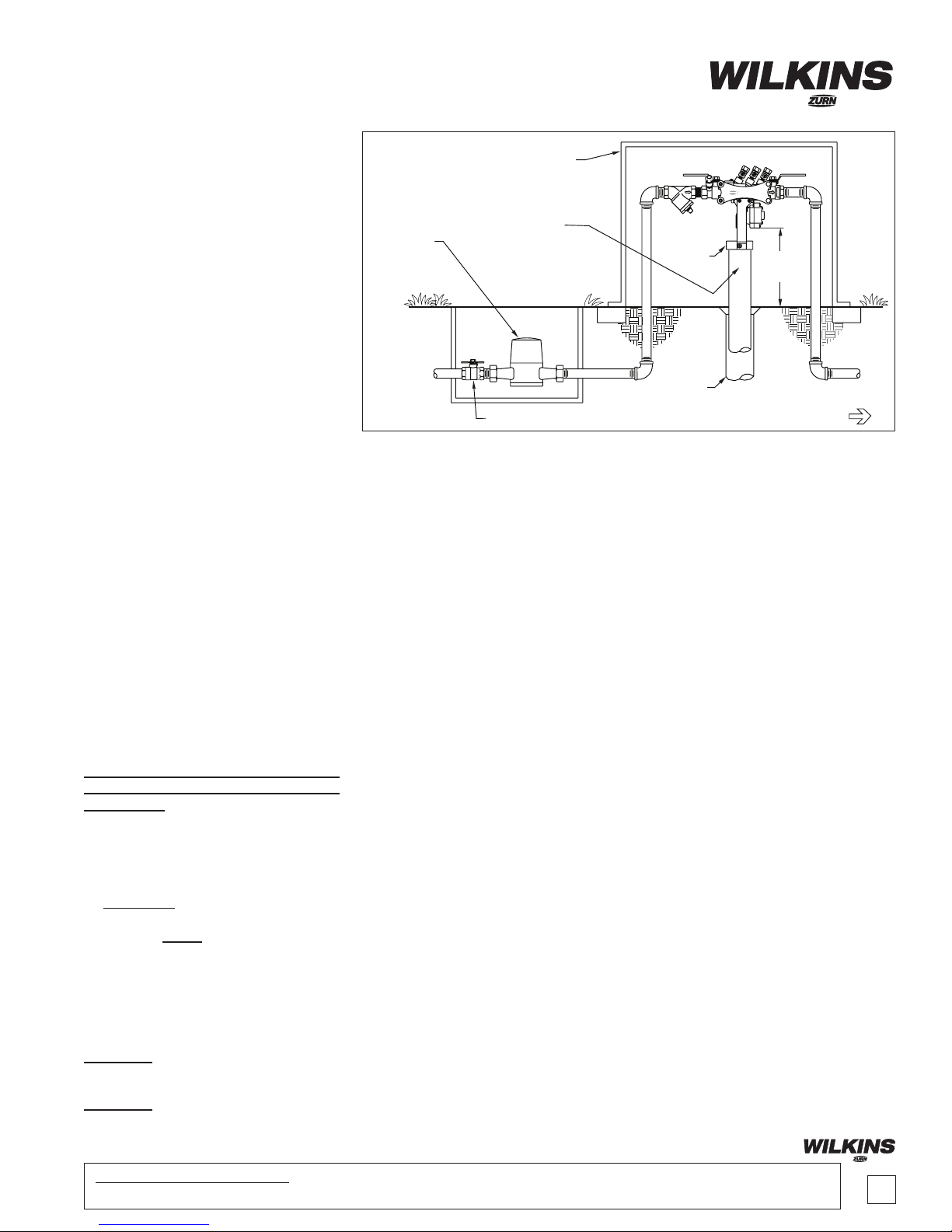
FLOOR
DRAIN
INLET SHUT OFF
DIRECTION OF FLOW
12" MIN.
30” MAX.
AIR GAP
OPTIONAL
WATER
METER
175 PSIG 180ß F
3/4" 375 RP
ZURN
WILKINS
2” PIPE
(DRAIN LINE CAN
BE ANY STANDARD
PIPING MATERIAL)
PROTECTIVE
ENCLOSURE
Model 375, 375XL
Reduced Pressure Principle (3/4"-1")
Installation Testing Maintenance Instructions
CAUTION: Installation of Backow Preventers must be performed by qualied,
licensed personnel. The installer should
be sure the proper device has been
selected for the particular installation.
Faulty installation could result in an
improperly functioning device.
WILKINS Model 375 Reduced Pressure
Principle Backow Preventers are for use
on potable water lines where a health
hazard could exist if a backow situation
were to occur.
Proper performance is dependent upon
following these installation instructions
and prevailing governmental and industry
standards and codes. Failure to do so,
according to WILKINS Limited Warranty
"...releases WILKINS of any liability that it
might otherwise have with respect to that
device." Such failure could also result in
an improperly functioning device.
Damage to the device could result wherever
water hammer and/or water thermal expansion could create excessive line pressure.
Where this could occur, shock arresters
and/or pressure relief valves should be
installed downstream of the device.
1. Before installing a Model 375 Backow
Preventer, ush the line thoroughly to remove
all debris, chips and other foreign matter. If required, a strainer should be placed upstream
of the Backow Preventer.
CAUTION: Do not use a strainer in seldom used emergency waterlines such
as re lines.
2. Provide adequate space around the
installed unit so that the test cocks will be
accessible for testing and servicing.
3. WARNING: If installation of a Model
375 is in a building, a suitable drain arrangement MUST be provided to drain
off spillage from the relief valve. An air
gap at least two times the pipe diameter
must be provided between the relief valve
and the drain piping to prevent a crossconnection. Air Gap AG-11 not intended
to support weight of drain pipe.
CAUTION: Do not pipe the relief valve
solidly to a oor drain, sewer or sump.
CAUTION: An adequately sized drain is
required to prevent possible water damage due to relief valve discharge.
4. Install valve at least 12 inches above
surrounding ood level.
5. Always consult local codes for installation methods, approvals and guidance.
OUTDOOR INSTALLATION
Model 375 Backow Preventers may be
installed outdoors only if the device is
protected against freezing conditions.
Exposure to freezing conditions will result
in improper function or damage to the
device. The installation location must be
kept above 32°F. All the basic installation
instructions apply.
If installation is in a pit or vault, the Backow Preventer must never be submerged
in water because this will cause a crossconnection. Make sure that the pit or vault
always remains dry by providing ample
drainage.
INDOOR INSTALLATION
Indoor installation is preferred in areas
that are subject to freezing conditions. All
the basic installation instructions apply to
such installations.
PARALLEL INSTALLATION
Where uninterrupted service from a single
meter connection must be maintained, two
or more Backow Preventers may be connected in parallel. All the basic installation
instructions apply to parallel installation.
Be sure to allow adequate room between
the units for testing and repair.
PLACING THE DEVICE IN SERVICE
After the installation of a Model 375 has
been completed, place the unit in service
as follows:
375 REDUCED PRESSURE PRINCIPLE
1. Start with both shut-off valves closed.
Slowly open the inlet shut-off valve until the
backow preventer is completely pressurized. A brief discharge from the relief valve
may occur while the device is pressurizing.
The discharge should cease by the time the
shut-off valve is fully open. Device should
function properly. If the discharge does not
stop, refer to "MAINTENANCE INSTRUCTIONS" for repair procedures.
2. After the device has been pressurized,
vent all trapped air from both check valves
by slightly opening each of the four test
cocks.
3. Slowly open the downstream shut-off
valve. The Model 375 Reduced Pressure
Principle Backow Preventer is now in
service.
4. If "spitting" or intermittent discharges
from the relief valve are noted, it could
be a result of pressure uctuation and/or
a water hammer condition in the system.
If such conditions exist, install a WILKINS
water pressure reducing valve, a WILKINS
Model 40XL check valve, or a WILKINS
Model 1250 water hammer shock arresters in compliance with industry standards
as needed.
5. After the Model 375 has been properly installed, test the device (see "TEST
PROCEDURES"). If the device fails the
test, remove the rst and second check
valves and thoroughly ush the device. If
the relief valve fails to operate properly,
inspect the sensing passage for clogging
(see "MAINTENANCE INSTRUCTIONS").
Clean rubber seals of all debris and place
unit back in service.
Proposition 65 Warning This product contains chemicals known to the State of California
to cause cancer or birth defects or other reproductive harm.
1
Page 2
Testing Procedures
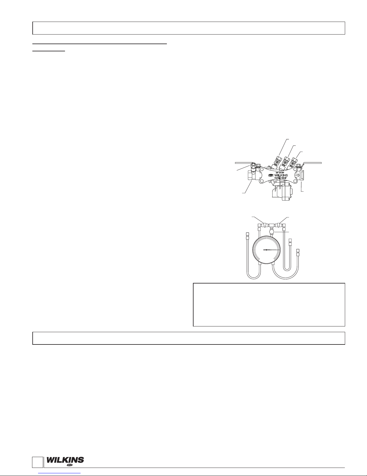
#1 TEST COCK
#2 TEST COCK
#3 TEST COCK
#4 TEST COCK
#1 SHUT-OFF
VALVE
VENT HOSE
LOW SIDE HOSE
HIGH SIDE HOSE
BY-PASS
VALVE "B"
BY-PASS
VALVE "C"
BY-PASS
VALVE "A"
#2 SHUT-OFF
VALVE
175 PSIG 180ß F
3/4" 375 RP
ZURN
WILKINS
a ® company
MODEL 375 REDUCED PRESSURE PRINCIPLE
ASSEMBLY
Equipment Required: Differential pressure gauge test kit.
TEST NO. 1
Purpose:
Test #2 check valve for tightness against reverse ow.
Requirement:
The valve must close tight against reverse ow under all pressure
differentials.
Procedure:
1. Attach the "HIGH" hose to test cock #2 and the "LOW"
hose to test cock #3.
2. Close #2 shut-off valve.
3. Open test cocks #2 and #3.
4. Open by-pass valves "C" and "A" and bleed to atmosphere
until all air is expelled.
5. Close by-pass valve "A". Open by-pass valve "B" and
bleed to atmosphere until all air is expelled. Close by-pass
valves "B" and "C".
6. Attach the "VENT" hose to test cock #4.
7. Slowly open by-pass valves "A" and "C" and keep by-pass
valve "B" closed.
8. Open test cock #4.
9. Indicated pressure differential will drop slightly. If pressure
differential does not continue to decrease, the #2 check
valve is considered tight.
TEST NO. 2
Purpose:
Test #1 check valve for tightness and record pressure drop across
#1 check valve.
Requirement:
The static pressure drop across the #1 check valve should be at
least 3.0 PSID greater than the relief valve opening point (TEST
NO. 3).
Procedure:
1. Close by-pass valve "A"
2. Close test cock #4, and disconnect "VENT" hose from test
cock #4.
3. Open by-pass valves "B" and "C" bleeding to atmosphere,
then close by-pass valve "B" restoring the system to
normal static condition.
4. Observe the pressure differential gauge and note this as
the #1 check valve psid.
Maintenance Instructions
All Model 375 Reduced Pressure Principle Backow Preventers
must be inspected and maintained by licensed personnel at least
once a year or more frequently as specied by local codes. Replacement of worn or damaged parts must only be made with genuine
"WILKINS" parts. The WILKINS Certicate of Limited Warranty
provides that failure to do so "...releases WILKINS of any liability
that it might otherwise have with respect to that device." Such
failure could also result in an improperly functioning device.
The Model 375 Reduced Pressure Principle Assemblies should
be thoroughly ushed after backow conditions occur to prevent
any type of corrosive deterioration to its components. Failure to
do so could result in malfunction of the device.
GENERAL MAINTENANCE
1. Clean all parts thoroughly with water after disassembly.
2
TEST NO. 3
Purpose:
To test operation of the differential relief valve.
Requirement:
The pressure differential relief valve must operate to maintain the
"ZONE" between the two check valves at least 2 PSID less than
the supply pressure.
Procedure:
1. Close by-pass valve "C" and open by-pass valve "A".
2. Open by-pass valve "B" very slowly until differential gauge
needle starts to drop. Hold the valve at this position and
observe the gauge reading at the moment the rst dis charge is noted from the relief valve. Record this as the
opening differential pressure of the relief valve.
WARRANTY: WILKINS Valves are guaranteed against defects of
material or workmanship when used for the services recommended.
If in any recommended service, a defect develops due to material or
workmanship, and the device is returned, freight prepaid, to WILKINS
within 12 months from date of purchase, it will be repaired or replaced
free of charge. WILKINS liability shall be limited to our agreement to
repair or replace the valve only.
2. Carefully inspect rubber seal rings, diaphragms and o-rings
for damage.
3. Test unit after reassembly for proper operation (see "Testing
Procedures").
SERVICING CHECK VALVES
1. Close inlet and outlet shut-off valves.
2. Open No. 2, No. 3 and No. 4 test cocks to release pressure
from valve.
3. Unscrew clamp screws, and remove clamp.
(inserting screw in center hole can remove stuck clamp).
Slide sleeve toward inlet pipe. Slide valve body toward
inlet and lift upward.
4. Using nger or blunt object, push in outlet end of body,
both checks should slide out the body inlet. (A phillips
screw driver will work in a 3/4" valve. The closed ball
valve handle will work in a 1" valve).
1747 Commerce Way, Paso Robles, CA 93446 Phone:805/238-7100 Fax:805/238-5766
WILKINS, a ZURN company
Page 3
a ® company
Maintenance Instructions
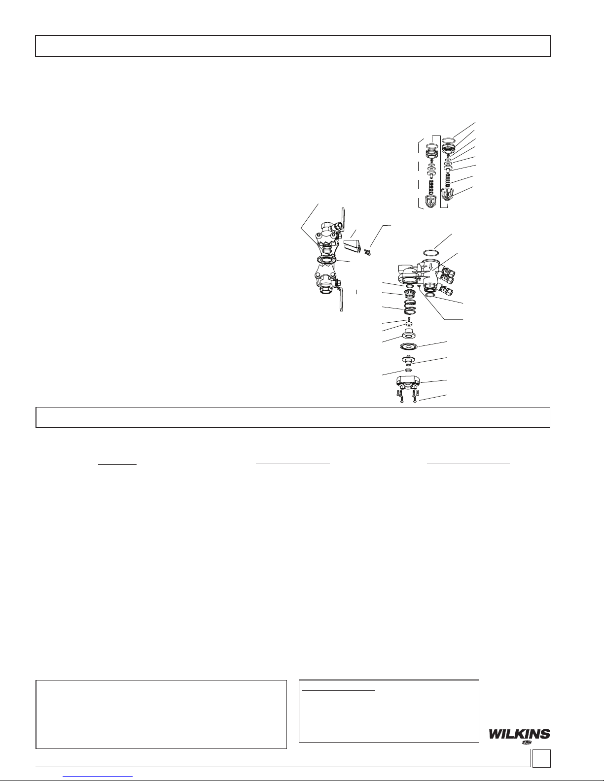
SEAT O-RING
#1 CHECK SEAT
POPPET SCREW
SEAL RING RETAINER
POPPET SEAL RING
POPPET
#1 CHECK SPRING
#1 CHECK SPRING
RETAINER
#2 CHECK ASSY.
BODY INLET O-RING
BODY
BODY OUTLET
O-RING
RV COVER O-RING
RV DIAPHRAGM
RV UPPER PLUNGER
RV COVER BOLT S
RV COVER
RV PLUNGER
O-RING
RV LOWER PLUNGER
RV SEAL RING
RV SCREW
RV SPRING
RV SEAT
RV SEAT
O-RING
SLEEVE
SLEEVE O-RING
CLAMP
CLAMP BOLT S
MODEL 375 3/4” - 1”
5. Twist spring retainers counter-clockwise to remove
from seat and access poppets.
6. Inspect the rubber seal ring for cuts or embedded debris.
To remove seal ring, remove screw and seal ring retainer. If the
reverse side of the seal ring is unused, it is possible to invert
the seal ring. This would be considered a temporary solution
to xing a fouled check and should be replaced with a new
seal ring as soon as possible.
7. Inspect seat surface for nicks or dings and replace if
necessary. Use ngernail to check for dings. Re-grease seat
o-rings.
8. Inspect seat o-ring sealing areas in body and wipe clean.
9. Reverse the above procedures to reinstall check valve
assembly. (Drop #2 check assembly in body. Then drop #1
check assembly in and turn until #1 spring retainer lines up with
#2 seat. Then push both assemblies into body.) Care should
be taken to make sure the heavy spring is installed in the No.
1 check valve. Do not overtighten clamp screws as this can
cause leak at the sleeve o-ring.
SERVICING RELIEF VALVE
1. Remove relief valve cover screws and cover. Gently
pull on diaphragm to remove the cartridge assembly.
2. Inspect seal ring for cuts and embedded debris.
Turn over or replace if required.
3. Disassemble cartridge by unscrewing relief valve
retaining screw.
4. Inspect diaphragm and o-ring for damage. Replace
required parts and apply a light coat of grease to
plunger o-ring, and place on plunger.
5. Carefully reassemble cartridge assembly.
6. Inspect relief valve seat for wear on seating surface.
If damaged, replace seat and seat o-ring. (Twist seat
and o-ring while inserting to keep it from popping out.
7. Insert cartridge assembly into relief valve cover.
8. Check cover o-ring in groove on body. Clean or replace
as necessary.
9. Replace relief valve cover and cover screws.
10. Place device in service and test per "TESTING PROCEDURES".
Troubleshooting
When the relief valve discharges intermittently it can be almost always assumed that the device is functioning correctly and that the discharge is caused
by systems problem such as inlet pressure uctuations or water hammer due to quick closing valves.
1. SUDDEN OR RAPID SPITTING
2. LIGHT INTERMITTENT DRIP
Continuous discharge of the relief valve signies a failure of some part of the device. To help determine the specic area of failure, close the #2 shutoff valve. If the discharge stops, the #2 check requires service. If the discharge continues, the #1 check requires service.
1. CONTINUOUS DISCHARGE 1. Fouled #1 check.
In summation, the amount of discharge is proportional to degree of fouling. Most problems occur in the #1 check which is where debris enters the
backow preventer rst.
Proper performance is dependent upon licensed, qualied personnel
performing regular, periodic testing according to WILKINS' specications and prevailing governmental & industry standards and codes
and upon following these installation instructions. Failure to do so
releases WILKINS of any liability that it might otherwise have with
respect to that device. Such failure could also result in an improperly
functioning device.
PROBLEM
1. Drop in inlet pressure.
2. Sudden increase in downstream
pressure due to water hammer from
quick closing shut-off valve installed
downstream.
1. Slightly fouled #1 check
2. Fouled relief valve seat.
3. Fouled #2 check.
POSSIBLE CAUSES
SPECIFICATIONS
Maximum working water pressure 175 PSI
Maximum working water temp. 180◦°F
Hydrostatic 350 PSI
End connections Threaded NPT
ANSI B1.20.1
A. Install an in-line spring loaded check
valve upstream of backow. (WILKINS
Model 40XL)
B. Install pressure reducing valve up
stream of backow unit. (WILKINS Model
BR4 or NR3XL)
C. Install in-line spring loaded check
valve downstream of backow as
close to source as possible, but not
closer than 4 feet. (WILKINS Model 40XL)
A. Clean #1 check and turn check valve
seal ring over or replace.
A. Clean check valves and turn check
valve seal rings over or replace.
B. Clean relief valve seat and turn
relief valve seal ring over or replace.
CORRECTIVE ACTION
WILKINS, a ZURN company
1747 Commerce Way, Paso Robles, CA 93446 Phone:805/238-7100 Fax:805/238-5766
3
Page 4
MODEL 375, 475 & 975 RP & RPDA
0
50
100
150
200
0 200 400 600 800
FLOW RATE (U.S. GPM)
ZONE PRESSURE (U.S. PSIG)
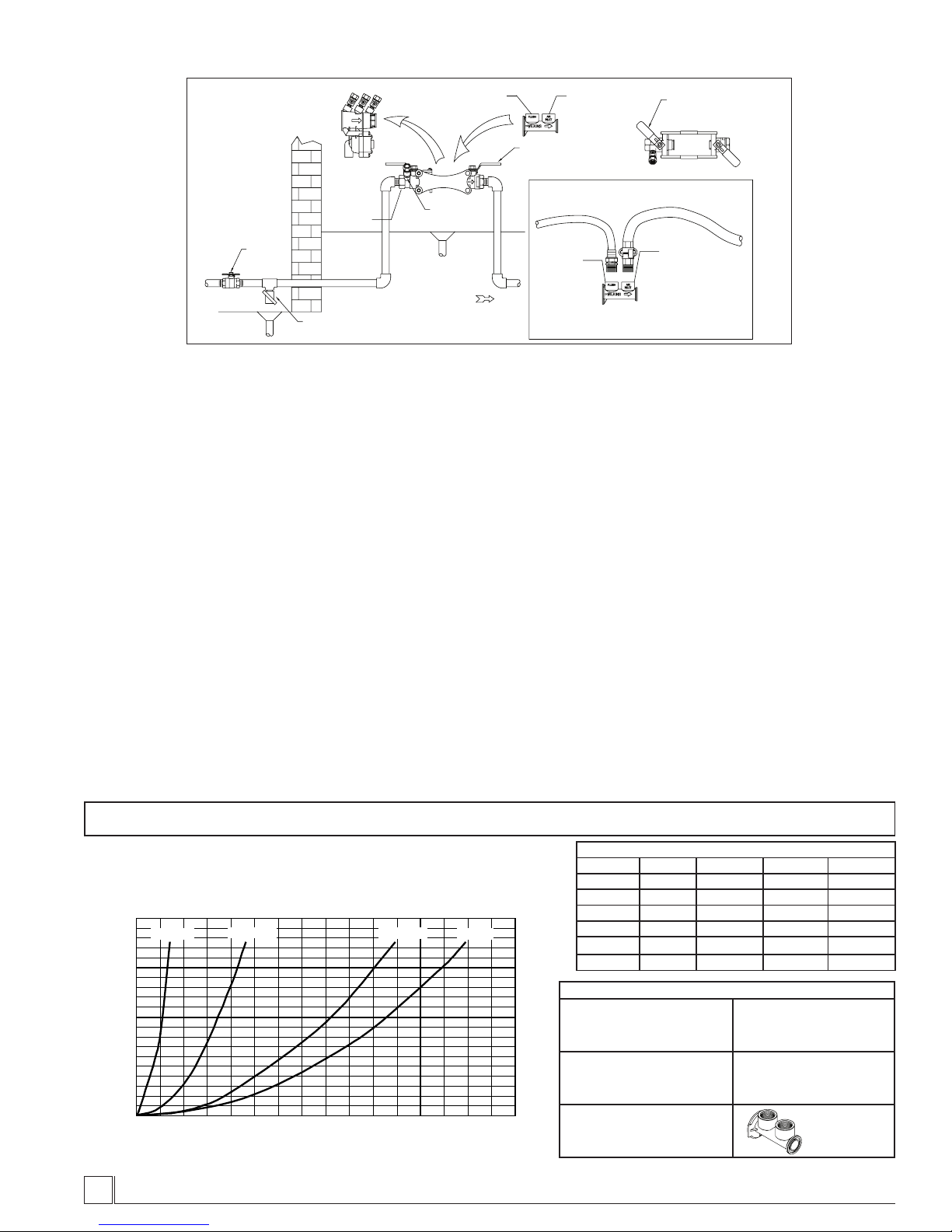
Blow Out / Flush Procedure for Freeze Protection
FLUSH OUT
HOSE
HOSE TO AIR
COMPRESSOR
AIR INLET
BLOW OUT
CONNECTION (6)
BLOW OUT/
FLUSH FITTING
FLUSH OUT
PORT (7)
(ADAPTERS AND HOSES
PROVIDED BY OTHERS)
OUTLET SHUT-OFF
VA LVE (5)
AIR INLET
BLOW OUT
CONNECTION (6)
3/4” NPT
BLOW OUT/
FLUSH FITTING
FLUSH OUT
PORT (7)
3/4” NPT
CHECK
HOUSING
MAIN
SHUT-OFF
VA LVE (1)
DRAIN
INLET DRAIN
VA LVE (2)
DIRECTION OF FLOW
DRAIN
TEST COCK (4)
MODEL 375
INLET
SHUT-OFF
VA LVE (3)
LEAVE BALL VA LVES AND
TEST COCKS 1/2 OPEN TO
PREVENT FREEZE DAMAGE
(RK34-375BOF, RK1-375BOF)
To Blow Out System for freeze protection, use the following
procedure:
1. Turn off main shut-off valve (1) that supplies water to
the system.
2. Open inlet drain valve in the system (2). Open inlet and
outlet shut-off valves on the backow preventer (3 & 5)
and all of the test cocks (4). Leave all valves and test
cocks in the half open/half closed (45°) position to allow
full drainage of the ball valves and test cocks.
3. Remove black backow preventer housing. Replace with
orange Blow Out / Flush tting. Store backow preventer
housing in a safe location for winter. Orange Blow Out /
Flush tting may remain in valve body during winter.
Place plugs in ports to keep debris from entering housing.
4. A hose and adapter can be connected to ush out port (7)
to drain water to a safe drain.
5. Connect an air hose and adapter to the air inlet connection
(6). Inject an adequate volume of air to remove all water
from the downstream portion of the system. Do not
allow the tting to overheat.
6. Leave drain valve (2), shut-off valves (3 & 5) and test
cocks (4) in the half open/half closed position (45°) for
the duration of the winter to prevent freezing.
7. Store valve housing/check assemblies, clamp/sleeve and
o-rings in sealed plastic bag during winter to prevent
weathering.
To Flush System during installation, use the following
procedures:
1. Install backow device in pipe system, leave water off.
2. Remove the black backow preventer housing from the
bronze body.
3. Install the orange Blow Out / Flush tting into the bronze
body.
4. Thread a garden hose adapter into Flush-Out port (7).
Connect a hose to the adapter and run to a safe drain.
Shut-off valves (3) and (4) should be open.
5. Turn on water supply at main shut-off valve (1) to ush
out any debris in the pipe. Turn water off.
6. Remove orange Blow-Out / Flush tting and replace
black check housing back into the line. Close shut-off
valves (3) and (4). Turn water on at main shut-off (1).
7. Slowly open shut-off valve (3) to pressurize backow
preventer. Once fully open, pressurize system by slowly
opening shut-off valve (4).
CAUTION: For freeze protection be certain that main shut-off valve (1)
remains tightly closed to prevent relling of the system. Also, the main
shut-off valve must be resilient seated to insure no leakage of water into
the system.
Performance Characteristics
(Worst case condition- If 1st check or relief valve is lodged wide open)
4
IS375-34-1 (REV. 3/09)
Relief Valve Discharge Rates
BACKFLOW PREVENTERS
3/4" - 1"
1-1/4" - 2"
Capacity thru Schedule 40 Pipe
Pipe size 5 ft/sec 7.5 ft/sec 10 ft/sec 15 ft/sec
1/2" 5 7 9 14
3/4" 8 12 17 25
1" 13 20 27 40
2-1/4" - 6"
8" - 10"
1 1/4" 23 35 47 70
1 1/2" 32 48 63 95
2" 52 78 105 167
REPAIR KITS FOR 375's
BLOW OUT/FLUSH FITTING VESSEL
3/4" RK34-375BOF 3/4" RK34-375V
1" RK1-375BOF 1" RK1-375V
COMPLETE INTERNALS WEDGE/CLAMP
1747 Commerce Way, Paso Robles, CA 93446 Phone:805/238-7100 Fax:805/238-5766
3/4" RK34-375 3/4" RK34-375W
1" RK1-375 1" RK1-375W
RUBBER PARTS
3/4" RK34-375R
BLOW OUT/
FLUSH FITTING
1" RK1-375R
WILKINS, a ZURN company
 Loading...