

WILKINS 350, 350ADA, 350DA, 350A Installation And Testing Instructions
a company
®
®
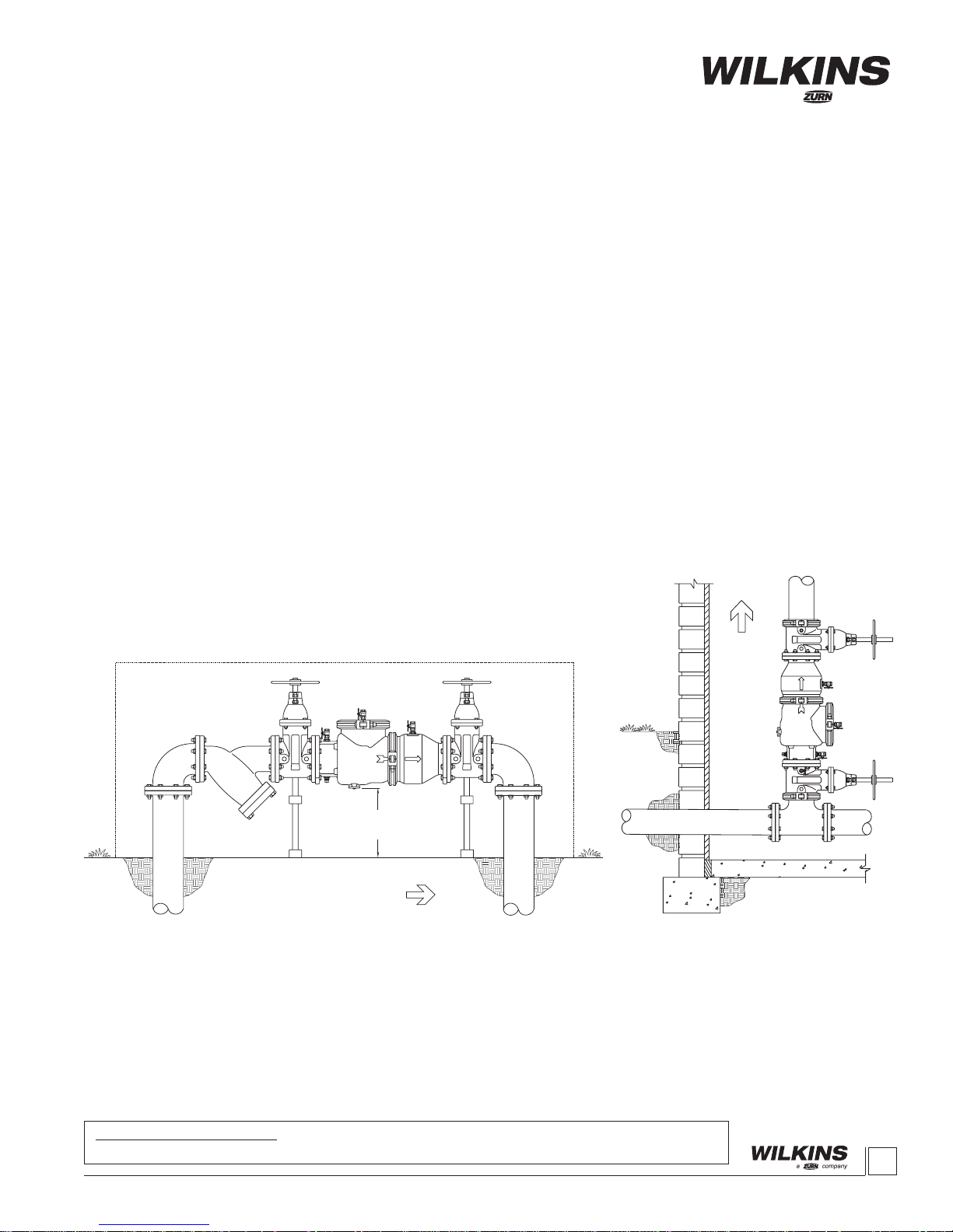
Model 350, 350A, 350ADA & 350DA
DIRECTION OF FLOW
12" MIN.
30" MAX.
DIRECTION OF FLOW
Double Check Valve Assembly (8”, 10” & 12”) and
Double Check Valve Detector Assembly (8”, 10” & 12”)
Installation Testing Maintenance Instructions
(Patent No. 5,913,331)
INSTALLATION INSTRUCTIONS
CAUTION: Installation of Backow Preventers must be performed by qualied, licensed
personnel. The installer should be sure the proper device has been selected for the
particular installation. Faulty installation could result in an improperly functioning device.
WILKINS Model 350 Double Check Valve assemblies are for use on potable water lines
where a health hazard does not exist in the event of a backow situation.
Damage to the device could result wherever water hammer and/or water thermal expansion could create excessive line pressure. Where this could occur, shock arrestors, check
valves and/or pressure relief valves should be installed downstream of the device.
If installation is in a pit or vault, the Backow Preventer must never be submerged in
water because this could cause a cross-connection. Make sure that the pit or vault always
remains dry by providing ample drainage.
1. Before installing a Model 350 Backow Preventer, ush the line thoroughly to
remove all debris, chips and other foreign matter. If required, a strainer should be
placed upstream of the Backow Preventer. CAUTION: Do not use a strainer in
seldom used emergency waterlines such as re lines.
2. Provide adequate space around the installed unit so that the test cocks will be
accessible for testing and servicing.
3. Install valve at least 12 inches above surrounding ood level.
PLACING THE DEVICE IN SERVICE
1. Start with both shut-off valves closed.
Slowly open the inlet shut-off valve until the
backow preventer is completely pressurized.
2. When the unit has been pressurized,
vent any trapped air by slightly opening
each of the four test cocks.
3. Slowly open the downstream shut-off
valve. The Model 350 Double Check Valve
assembly is now in service.
4. After the Model 350 has been properly
installed, test the device (see “TEST PROCEDURES”). If the device fails the test,
remove the rst and second check valves
and thoroughly ush the device. Clean rubber and seats of all debris and place unit
back in service.
4. Always consult local codes for installation methods, approvals and guidance.
OUTDOOR INSTALLATION
The Model 350 Backow Preventer may
be installed outdoors only if the device
is protected against freezing conditions.
Exposure to freezing conditions will result
in improper function or damage to the
device. The installation location must be
kept above 32°F. All the basic installation
instructions apply.
INDOOR INSTALLATION
Indoor installation is preferred in areas that
are subject to freezing conditions. All the
basic installation instructions apply to such
installations.
VERTICAL INSTALLATION
Vertical installation is acceptable in applications where inlet and outlet piping
are flowing vertically upwards. All the
basic installation instructions apply to such
installations. Consult factory for approval
status.
Proposition 65 Warning This product contains chemicals known to the State of
California to cause cancer or birth defects or other reproductive harm.
1
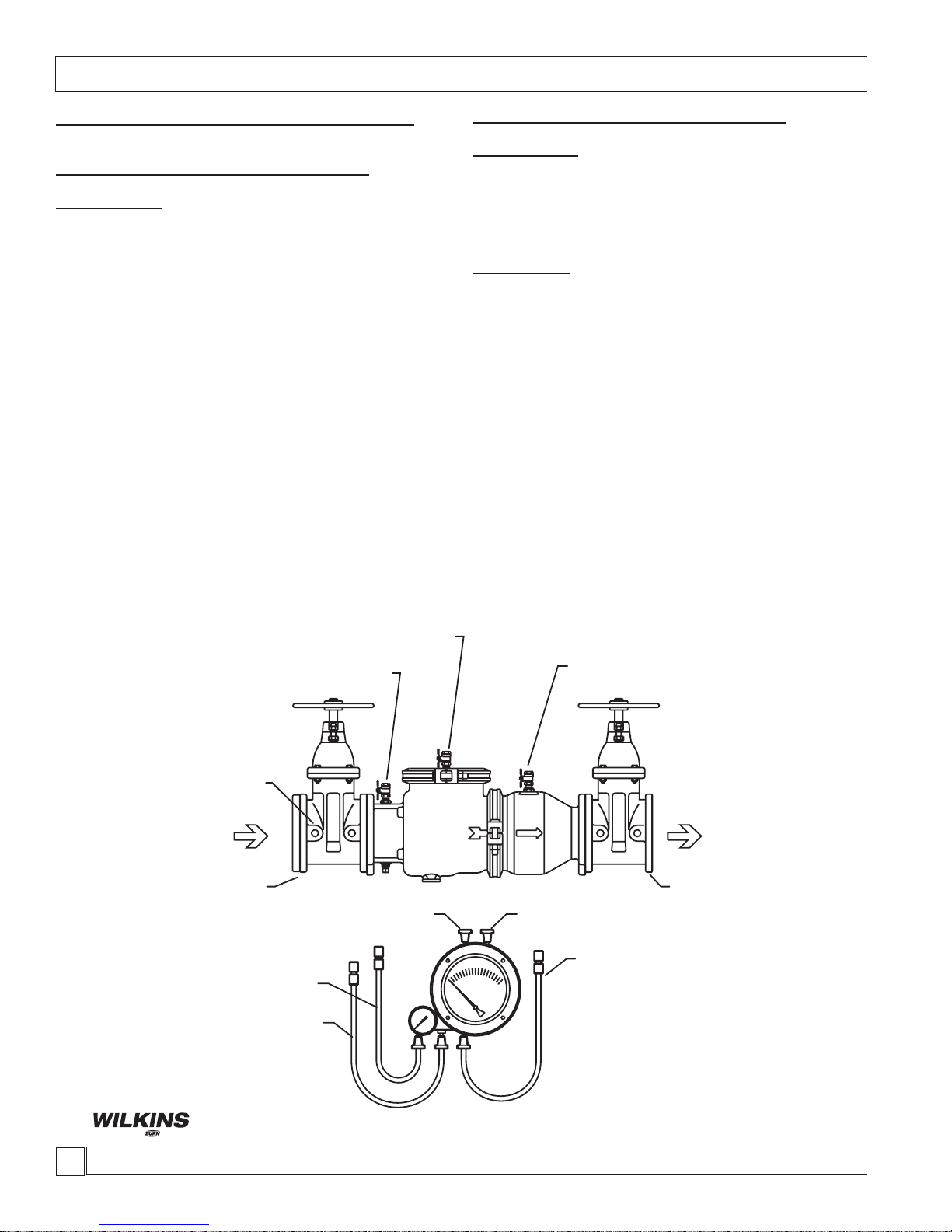
VENT HOSE
LOW SIDE HOSE
HIGH SIDE HOSE
LOW SIDE BLEED
NEEDLE VALVE
#1 TEST COCK
#4 TEST COCK
#3 TEST COCK
#2 TEST COCK
#2 SHUT-OFF
VALVE
#1 SHUT-OFF
VALVE
HIGH SIDE BLEED
NEEDLE VALVE
Testing Procedures
a company
®
®
MODEL 350 DOUBLE CHECK VALVE ASSEMBLY
Equipment Required: Differential pressure gauge test kit.
TEST NO. 1 - TIGHTNESS OF #1 CHECK VALVE
REQUIREMENT:
The static pressure drop across check valve #1 shall be at least
1.0 psid. If test cock #3 is not at the highest point of the check
valve body, then a vertical tube must be installed on test cock #3
so that it rises to the top of the check valve body.
PROCEDURE:
1. Slowly open all 4 test cocks to remove any foreign material
and attach ttings.
2. Attach hose from the high side of the test kit to the #2 test cock.
3. Open test cock #2 and bleed all air from the hose and gauge
by opening the high side bleed needle valve. Close high side
bleed needle valve. If a tube is attached to test cock #3, open
test cock #3 to ll the tube. Close test cock #3. Close #2
shut-off valve then close the #1 shut-off valve.
4. Hold gauge at same level as test cock #3 or water level in tube.
Slowly open test cock #3. Record the static pressure drop
across check valve #1 after gauge reading stabilizes and
water stops running out of test cock #3.
5. Close all test cocks, open shut-off valve #1 and remove test
equipment.
TEST NO. 2 - TIGHTNESS OF #2 CHECK VALVE
REQUIREMENT:
The static pressure drop across check valve #2 shall be at least
1.0 psid. If test cock #4 is not at the highest point of the check
valve body, then a vertical tube must be installed on test cock #4
so that it rises to the top of the check valve body.
PROCEDURE:
1. Attach hose from the high side of the test kit to the #3 test cock.
2. Open test cock #3 and bleed all air from the hose and gauge
by opening the high side bleed needle valve. Close high
side bleed needle valve. If a tube is attached to test cock
#4, open test cock #4 to ll the tube. Close test cock #4.
Close #1 shut-off valve.
3. Hold gauge at same level as test cock #4 or water level in
tube. Slowly open test cock #4. Record the static pressure
drop across check valve #2 after gauge reading stabilizes and
water stops running out of test cock #4.
4. Close all test cocks, slowly open shut-off valve #1 & #2 and
remove test equipment.
WILKINS, a ZURN company
2
1747 Commerce Way, Paso Robles, CA 93446 Phone:805/238-7100 Fax:805/238-5766
 Loading...