

Wilkerson WRA-0250-2, WRA-0250-3, WRA-0250-4, WRA-0300-2, WRA-0300-3 Owner's/operator's Manual
...Page 1
READ ALL INFORMATION IN THIS MANUAL BEFORE BEGINNING
INSTALLATION OR OPERATION OF THE DRYER. BEFORE STARTING
INSTALLATION AND/OR MAINTENANCE PROCEDURES, TURN OFF
THE MAIN POWER TO THE DRYER AND COMPLETELY
DEPRESSURIZE THE UNIT TO PREVENT PERSONAL INJURY.
DO NOT REMOVE, REPAIR, OR REPLACE ANY ITEM ON THIS DRYER
WHILE IT IS UNDER PRESSURE.
THIS DRYER USES REFRIGERANT R-22. COMPLY WITH ALL LOCAL,
STATE, AND FEDERAL REGULATIONS CONCERNING REFRIGERANT
WHEN PERFORMING ANY MAINTENANCE OR SERVICE ON THE
REFRIGERATION SYSTEM. ALL REFRIGERATION SYSTEM REPAIRS
OR MAINTENANCE NOT DETAILED IN THIS MANUAL SHOULD BE
DONE BY A QUALIFIED REPAIR PERSON.
NEVER OPERATE THIS DRYER ABOVE THE RATED OPERATING
CONDITIONS. OPERATION ABOVE SPECIFIED CONDITIONS WILL
RESULT IN DECREASED PERFORMANCE, POSSIBLE DAMAGE TO
THE UNIT AND/OR PERSONAL INJURY.
®
OWNER/OPERATOR MANUAL
COMPONENTS, INSTALLATION, OPERATION
AND SERVICE INSTRUCTIONS
REFRIGERATED COMPRESSED AIR DRYER
WRA 0250-WRA 0500
WRW 0250-WRW 0500
WARNING
83-030-000-FL • Rev. A • 9/95
Printed in the U.S.A.
REFRIGERATED AIR DRYER
SYSTEM MONITOR
POWER ON
HIGH TEMP
OUTLET
ORESSYRE
OUTLET
ORESSYRE
®
OPERATIONS
For further assistance contact:
P.O. Box 1237
1201 W. Mansfield Ave.
Englewood, CO 80150
Phone (269) 629-2550
FAX (269) 629-2475
Certificate No
BSI
R
E
G
I
S
T
E
R
E
D
F
I
R
M
NATIONAL
ACCREDITATION
OF CERTIFICATION
BODIES
®
R
E
G
I
S
T
E
R
E
D
F
I
R
M
WILKERSON OPERATIONS
REGISTERED TO ISO 9001
CERTIFICATE NO. A2192
FM21121
Page 2

WILKERSON OPERATIONS Page 1
Table of Contents
Why you need a Wilkerson Dryer and recommended Typical Installation..................Page 2
Components of a Refrigerated Dryer Compressed Air System....................................Page 3
Dryer Performance Specifications...................................................................................Page 4
Installation Instructions and Start-up Procedure...........................................................Page 5
Preventive Maintenance, Dryer Dimensions and
Recommended Wilkerson Air Accessories ....................................................................Page 6
Compressed Air Circuit ....................................................................................................Page 7
Refrigeration Circuit..........................................................................................................Page 8
Control Panel Components..............................................................................................Page 9
Electrical Box Components ...........................................................................................Page 10
Refrigeration Components ............................................................................................Page 11
Cabinet Components ......................................................................................................Page 12
Wiring Diagrams.........................................................................................................Page 13-14
Trouble Shooting Guide..................................................................................................Page 15
Dryer Warranty ................................................................................................................Page 16
Service Information.........................................................................................................Page 17
Page 3
Page 2 WILKERSON OPERATIONS
WHY YOU NEED A WILKERSON
REFRIGERATED AIR DRYER
Untreated compressed air will contain contaminants
such as water, compressor oil, rust, chemical contaminants, and bacterial growth.
All of these contaminants will cause corrosion and
product contamination.
With proper filtration and a Wilkerson refrigerated air
dryer in use, contaminants will be reduced to a harmless level.
The end result will be that the equipment which comes
in contact with dry, treated, compressed air will stay
cleaner, will not corrode, and will last longer.
Rejection rates of your end products will drastically
reduce when using dry, treated air in your plant
manufacturing operation.
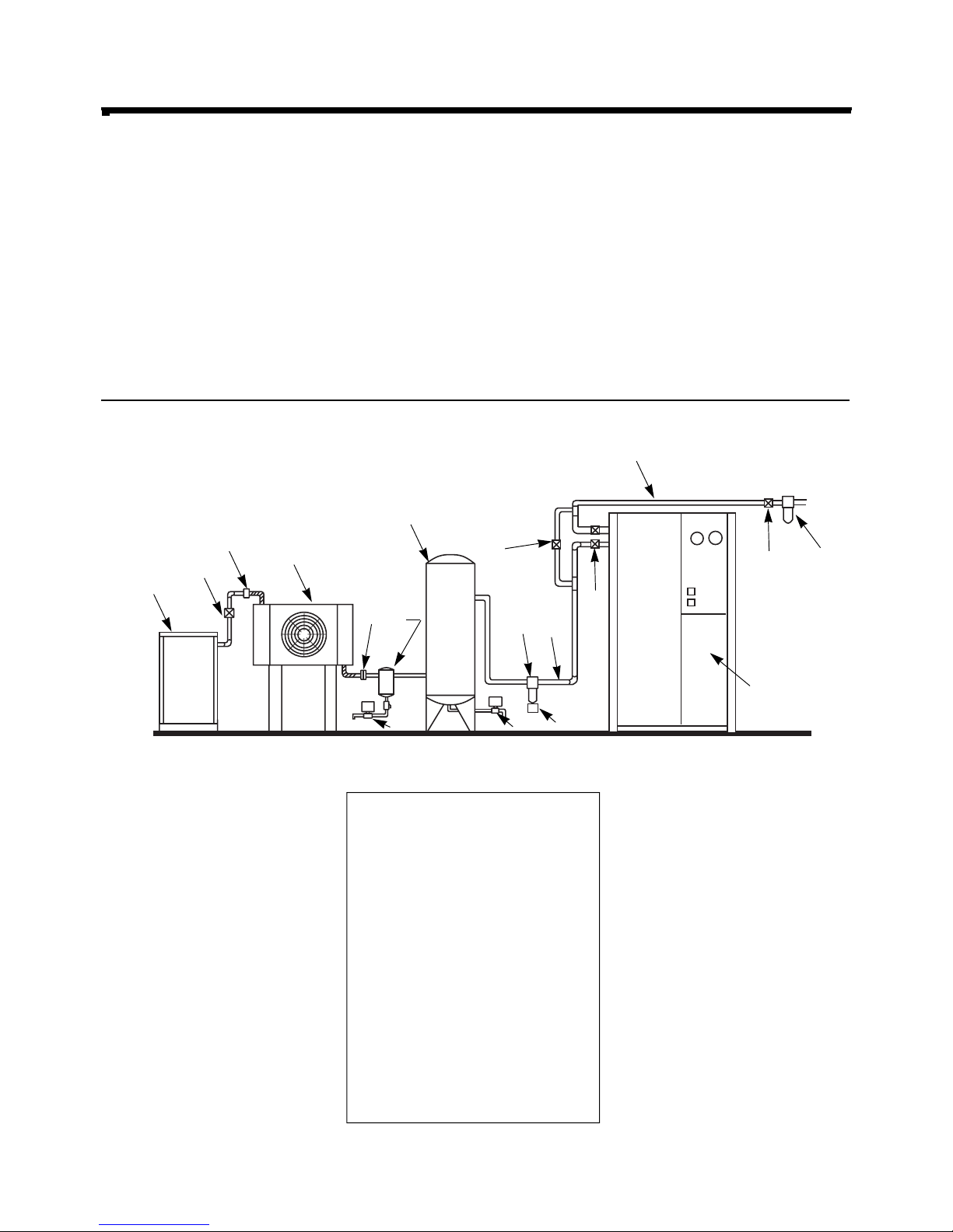
FIGURE 1: TYPICAL COMPRESSOR ROOM LAYOUT:
1 Air Compressor
2 Shut-off Valve
3 Flex Connector
4 Compressed Air Aftercooler
5 Flex Connector
6 Liquid Separator with
Electric Drain
7 Storage Tank
8 Prefilter
9 Electric Drain Valve
10 Flex Connector
11 Shut-off Valve
12 By-pass Valve
13 Flex Connector
14 Shut-off Valve
15 Afterfilter
16 Refrigerated Air Dryer
1
2
3
4
7
13
11
14
15
16
12
5
6
9
9
9
8
10
Page 4

WILKERSON OPERATIONS Page 3
The Air Compressor 1
Although there are many types of compressors, all have
some type of inlet filtration. If this filtration is not maintained
or is not properly designed for ambient conditions (ie. large
amounts of coal dust, road dust, fly ash, etc.) the result will
be increased compressor maintenance and an additional
contamination load on downstream equipment.
Shut-Off Valve 2, 11, 14
Sized in accordance with air flow capacities, to provide the
minimum pressure drop.
Flexible Connections 3, 5, 10, 13
Flexible piping between a compressed air system and the air
dryer or aftercooler is recommended to eliminate any
possible vibration induced damage.
The Aftercooler 4
As the name implies, the aftercooler cools the hot air after
compression. This not only reduces the temperature of the
air to within acceptable values for downstream equipment,
but also condenses out a very large amount of water. This is
very important because for approximately every 20°F (11°C)
reduction in compressed air temperature, one half of the
water is condensed. A separator must be used to actually
remove the water from the system.
The Separator 6
The separator removes the large droplets of oil and water
from the compressed air stream which condense in the
aftercooler, subsequently improving the dryer capacity.
Though one of the least expensive components of the
compressed air system, the separator is one of the most
critical. A difference of only a few percent efficiency in a
separator can allow substantial amounts of additional water
to pass downstream, both overloading a dryer and causing
potential maintenance problems. A properly sized electronic
drain should be installed to drain away accumulated liquids.
Storage Tank 7
This acts as a storage vessel which will also remove liquids.
Therefore, an electric drain valve should be installed. (Note:
Where possible the receiver should be installed with the
inlet near the bottom and the outlet near the top.)
Prefiltration 8
Wilkerson refrigerated air dryers will operate efficiently and
reliably without filtration. But if your system also requires dirt
and oil free air, then appropriate particulate or coalescing
filtration is required.
Electric Drains 9
Proper drainage of accumulated liquids is essential to proper
system operation. Should liquids be allowed to build up in
receivers and filters, liquid “slugging” can occur causing loss
of performance to downstream components.
Automatic electric drain valves provided on the dryers
automatically drain liquid water from the dryer evaporator and
separator. They feature full adjustment of drain cycles from 1
to 45 minutes, and valve opening durations from 1 to 15
seconds. Two indicator lights for indicating “power on” and
“valve open” status allow for easy visual inspection. Electric
drains are also recommended for all other drain points in the
compressed air system including separators, filters,
receivers, and drip legs.
By-pass Valve System 12
It is strongly recommended that a by-pass valve system be
utilized to provide for convenient maintenance and service.
Applications which require a continuous supply of dry air
should consider installing two dryer systems. This will assure
a steady supply of dry air under any conditions.
Afterfiltration 15
For critical applications, to obtain a maximum downstream oil
content of .01 ppm/wt and .003 ppm/wt respectively. See the
chart below for recommended afterfilters.
The Refrigerated Air Dryer 16
The Wilkerson Refrigerated Air Dryer is the result of
unprecedented research and testing. It is subjected to
simulated no load, partial load and full load performance
examinations to meet our quality standards. As such, it will
provide years of reliable service if properly installed and
operated within its design specifications. The dryer should be
installed in a well ventilated area.
Components Of A Refrigerated Dryer Compressed Air System
Recommended Filtration
Recommended Coalescing Prefilters/Afterfilters
Dryer Dryer/Filter
Model Pipe Type A Type B1 Type C
Number Size 5.0 Micron 1.0 Micron (.01 ppm downstream
Inlet/Outlet Particulate Coalescing remaining oil content)
WR( )-0250 2" NPT F35-0
C-0
00 M35-0C-S00 M35-0C-000
WR( )-0300 2" NPT F35-0
C-0
00 M35-0C-S00 M35-0C-000
WR( )-0400 2" NPT F35-0
C
-000 M36-0C-S00 M36-0C-000
WR( )-0500 2" NPT F35-0
C
-000 M36-0C-S00 M36-0C-000
NOTE: Recommended filters were selected on the basis of flow capacity—not pipe size.
Page 5

Page 4 WILKERSON OPERATIONS
Water-Cooled Performance Specifications (60 Hz)
Performance Specifications: Flow Capacity (dm
3
/s) (50Hz)
Air-Cooled Performance Specifications (60 Hz)
Flows* at 37.7° C Comp Full
Model Inlet Air Temperature Rating Load Shipping
Number 2-4°C Dew Point** Voltage (HP) Amps Weight
(dm3/s/hr)
WRA-0250-4 99 380/50/3 2.0 4.4 660
WRA-0300-4 118 380/50/3 2.5 5.2 675
WRA-0400-4 158 380/50/3 3.2 6.4 690
WRA-0500-4 197 380/50/3 3.8 7.7 700
All inlet and outlet air connections are: 2" NPT.
Specifications apply to air-cooled, water-cooled and 50 hertz.
Air flow rates are based on 100 psig (7 bar) inlet pressure and 100°F inlet air temperature.
System
COMPRESSOR DATA Full
Model SCFM Load Fan
Number Flow Voltage HP Full Load Amps LRA Amps CFM Shipping
WRA-0250-2 250 230/60/1 2.0 9.9 53 12.1 1700 660
WRA-0250-3 250 230/60/3 2.0 6.6 49 8.8 1700 660
WRA-0250-4 250 460/60/3 2.0 3.3 24 4.4 1700 660
WRA-0300-2 300 230/60/1 2.5 12.7 64 14.9 1700 675
WRA-0300-3 300 230/60/3 2.5 7.7 49 9.9 1700 675
WRA-0300-4 300 460/60/3 2.5 3.9 24 5.0 1700 675
WRA-0400-2 400 230/60/1 3.2 17.2 95 19.4 1870 690
WRA-0400-3 400 440/60/3 3.2 10.8 65 13.0 1870 690
WRA-0400-4 400 460/60/3 3.2 5.3 27 6.4 1870 690
WRA-0500-2 500 230/60/1 3.8 21.5 46 23.7 1870 700
WRA-0500-3 500 230/60/3 3.8 13.3 92 15.5 1870 700
WRA-0500-4 500 460/60/3 3.8 6.6 116 7.7 1870 700
System
COMPRESSOR DATA Full
Model SCFM Load
Number Flow Voltage HP Full Load Amps LRA Amps Shipping
WRA-0250-2 250 230/60/1 2.0 9.9 53 9.9 660
WRA-0250-3 250 230/60/3 2.0 6.6 49 6.6 660
WRA-0250-4 250 460/60/3 2.0 3.3 24 3.3 660
WRA-0300-2 300 230/60/1 2.5 12.7 64 12.7 675
WRA-0300-3 300 230/60/3 2.5 7.7 49 7.7 675
WRA-0300-4 300 460/60/3 2.5 3.9 24 3.9 675
WRA-0400-2 400 230/60/1 3.2 17.2 95 17.2 690
WRA-0400-3 400 440/60/3 3.2 10.8 65 10.8 690
WRA-0400-4 400 460/60/3 3.2 5.3 27 5.3 690
WRA-0500-2 500 230/60/1 3.8 21.5 46 21.5 700
WRA-0500-3 500 230/60/3 3.8 13.3 92 13.3 700
WRA-0500-4 500 460/60/3 3.8 6.6 116 6.6 700
Page 6

Installation Instructions
NOTE: ALL ELECTRICAL AND MECHANICAL
CONNECTIONS MUST BE MADE BY A
QUALIFIED PERSON.
1. The dryer needs to be installed in a well ventilated area.
There needs to be 12" (30 cm) clearance for the
condenser air inlet of the dryer.
2. In the location the dryer is installed the ambient
temperature should not exceed 110°F (43°C) or fall
below 40°F (4.4°C).
3. The inlet compressed air should not exceed 120°F
(49°C). NOTE: EXCESSIVE AMBIENT OR INLET AIR
TEMPERATURE WILL RESULT IN UNSATISFACTORY
PERFORMANCE AND IF NOT REMEDIED CAN
RESULT IN PERMANENT DAMAGE TO THE DRYER.
4. The dryer must be mounted on a suitable structure,
on an elevated, or flat and level floor.
5. It is recommended, that the air system be installed
similar to the layout shown in Fig.1 Page 2. Using shutoff valves and by-pass valves will allow for servicing of
the filters, drain valves, and dryer removal without
shutting down the compressed air system.
6. Electric drain connections must be made in manner that it
will not interfere with the flow. The discharge needs to be
treated in accordance with local and national EPA
code/regulations.
7. Verify that the “service voltage” is correct and that the
dryer is not wired to cycle with the air compressor, the
power to the dryer must be continuous.
8. Pressurize the air system, check for leaks and correct.
9. For “water cooled condensers” the water flow rate must
not be lower than what is specified on page 4, and the
incoming water temperature must not exceed 80°F.
WARNING: NEVER REMOVE THE ELECTRICAL
CONTROL PANEL WITHOUT TURNING OFF
ELECTRICAL SERVICE DISCONNECT TO THE DRYER
Start-up Procedure
NOTE: THE DRYER HAS A REFRIGERANT CRANKCASE
HEATER. PRIOR TO INITIAL START-UP THE
CRANKCASE HEATER SHOULD BE ENERGIZED FOR 24
HOURS BEFORE TURNING ON THE DRYER.
POWER TO THE CRANKCASE HEATER IS SUPPLIED
WHEN THE MAIN ELECTRICAL SERVICE DISCONNECT
IS TURNED ON. THE POWER ON/OFF SWITCH OF THE
DRYER HAS NO CONTROL OF THE CRANKCASE
HEATER.
LEAVE THE POWER ON/OFF SWITCH OFF
FOR THE FIRST 24 HOURS.
Do not start the dryer with an air load, bypass the airflow
before turning on the dryer.
By pushing the power switch to the on position the green light
will illuminate, the red high temperature light will come on
briefly and then go off. If the red light remains on for over 3
minutes thru the dryer off and refer to the trouble-shooting
guide.
The fan will not come on immediately, it will cycle in
accordance with the head pressure. Without any air load
through the dryer, the fan may stay off up to 5 minutes before
coming on; this is normal.
If the dryer is equipped with a refrigerant suction pressure
gauge, it should be indicating between 57-65 psig without any
air load.
Open the air by-pass valve and allow full air flow thru the
dryer.
Various dryer functions and conditions can be monitored.
Temperature at the probe locations will be displayed on
digital display (optional) by rotating the selector knob.
Simultaneously, pressure, air and refrigerant, can be
monitored on the analog gauges.
MAXIMUM INLET AIR TEMPERATURE: 120° F
MAXIMUM INLET AIR PRESSURES: 200 PSIG
MAXIMUM AMBIENT AIR TEMPERATURE: 110° F
MAXIMUM INLET WATER COOLED CONDENSER TEMPERATURE: 80° F
Water Flow Requirements at Various Water
Temperatures
Gallons per hour at the following temperatures
60°F 70°F 80°F
WRW-0250 80 100 132
WRW-0300 100 125 165
WRW-0400 120 150 198
WRW-0500 140 175 231
WILKERSON OPERATIONS Page 5
Page 7

Page 6 WILKERSON OPERATIONS
Preventive Maintenance Cont.
A. Weekly Checklist
1. Check Air-Cooled condenser coil for contaminants and
clean as required. Check Water-Cooled condenser coil for
proper water flow.
2. Inspect all electrical drains for operation. Turn off the shutoff valve and depress the manual override switch on the
electrical valve, this will depressurize the discharge line,
and clean the “Y” strainers.
3. Assure dryer inlet temperature does not exceed 120°F
(48°C).
4. Assure dryer ambient temperature does not exceed
110°F (43°C) and there are no ventilation obstructions
around the dryer. Ventilate the area and remove
obstructions as required.
5. Check separator, receiver, filter drains and strainers.
Check filter high differential pressure indicators, and
replace fouled elements as needed.
B. Semi-Annual Checklist
1. Remove and inspect all air system filters for excessive
particulate loading and physical damage. Replace the
filters that show any sign of damage, or if pressure drop
exceeds 7 psid (0,5 bar).
2. Shut off drain shut-off valves and clean “Y” strainers.
Disassemble solenoid valves if necessary and check for
contaminants. Clean as required.
10.38
9.36
7.88
6.50
.50
67.88
60.75
54.75
35.42
6.75
5.06
1/4" NPT DRAIN
LOCATIONS
POWER CORD
ACCESS
AIR INLET
AIR OUTLET
7.56
10.25
12.87
25.25
29.62
1
/2 NPT (FEMALE)
WATER OUTLET
1
/2 NPT (FEMALE)
WATER INLET
(WATER
CONNECTIONS
FOR WRW ONLY)
Air-Cooled and Water-Cooled Dryers
Dimensions
Page 8

WILKERSON OPERATIONS Page 7
The Compressed Air Circuit
Hot, saturated, compressed air first enters the air-to-air heat
exchanger “A”, where it is precooled by the exiting dry outlet
air. By precooling the incoming air, energy is saved by
reducing the heat load imposed on the refrigeration system.
As soon as the incoming air comes in contact with the cooler
air, condensation begins.
The saturated air then enters the evaporator (section “B”)
where the air temperature is reduced to 35°F to 39°F
(1.6° to 3.8°C). The water vapor is condensed and drained
off. The cold air then flows through the separator “C” where,
by gravity and vortex action the condensed water and
contaminants are collected in a “quiet zone” at the bottom of
the separator and are discharged through an automatic drain
valve. Our unique and highly efficient separator design
combines centrifugal action, directional flow change,
impingement, and velocity reduction to achieve superior
performance.
The dry chilled air then reenters the air-to-air exchanger
where it precools the incoming air and in turn is reheated.
Reheating of the air does not affect its dew point. The chilled
air flows in a counter flow thereby assuring high temperature
differential throughout the heat exchanger. The reheating
of the air prevents moisture condensation on the air
system piping.
AIR TO AIR AND EVAPORATOR
FLOW SCHEMATIC
REFRIGERANT IN
REFRIGERANT OUT
X17 Drain
Air Outlet
Air Inlet
EVAPORATOR
“B”
AIR TO AIR HEAT EXCHANGER
“A”
WATER
SEPARATOR
“C”
REFRIGERATION
EVAPORATOR
COIL
Page 9

Page 8 WILKERSON OPERATIONS
The refrigerant compressor (“A”) increases the pressure and
the temperature of the returning suction vapor containing the
latent heat removed from the air by the evaporator (“B”). This
high pressure vapor is then condensed by being cooled in the
condenser (“C”). The condenser surrenders the heat to the
surrounding ambient.
The liquid refrigerant flows from the receiver through a liquid
line heat exchanger located in the suction line (“H”), through
the filter/dryer (“E”), and the the thermostatic expansion valve
(“F”), which regulate the flow of refrigerant into the evaporator
(“B”). The liquid refrigerant removes the heat from the
compressed air by evaporation. The hot-gas bypass valve
(“G”) controls the temperature of the evaporator by sensing
low evaporator pressure and injecting hot discharge gas to be
mixed with the liquid refrigerant entering the evaporator,
creating an artificial load during low load operation to prevent
ice from forming in the evaporator.
The refrigerant now flows to the suction accumulator (“D”),
where any liquid refrigerant is intercepted allowing only vapor
to return to the compressor completing the refrigeration cycle.
Refrigeration Circuit
SUCTION
ACCUMULATOR
(D)
EXPANSION
VALVE
(F)
HOT GAS
BY-PASS VALVE
(G)
TXV
BULB
EXTERNAL
EQUALIZER
LINE
FILTER
DRYER
(E)
EVAPORATOR
(B)
LIQUID
LINE HEAT
EXCHANGER
(H)
COMPRESSOR
(A)
CONDENSER
(C)
AIR FLOW
DISCHARGE
SUCTION
Page 10

WILKERSON OPERATIONS Page 9
CONTROL PANEL COMPONENTS
Item Description Part Number
1 On/Off Switch 87-379-000
2 High Temperature Light 87-382-000
3 Air Pressure Gauge 49-111-000
4 Refrigerant Pressure Gauge 49-093-000
5 Digital Display 87-508-000
6 Selector Knob 87-470-000
Check air compressor aftercooler system. Clogged or fouled heat exchanger surfaces in the aftercooler (water or air cooled) are
the principal cause of high inlet air temperatures to dryer.
Check air compressor as well. Lack of lubrication, excessive wear, compressor undersized (i.e. substantial increase in air
consumption without adding to compressor capacity: oil cooler malfunction, etc.)
If high ambient temperature is the problem, immediately begin to cool dryer area with ventilating fans, open windows, louvers,
etc. Sustained high temperatures will damage dryer.
Dryer Indicates “High Inlet Temperature”
Page 11

Page 10 WILKERSON OPERATIONS
ELECTRICAL COMPONENTS:
Item Description Voltage Model Number Part Number
1 Transformer ALL ALL 87-044-000
2 Contactor ALL ALL 87-063-000
3 Fuse Holder ALL ALL 87-209-000
4 Fuse 1.0 AMP ALL ALL 87-210-000
5 Electrical Outlet ALL ALL 87-246-000
6 Electrical Enclosure ALL ALL 87-685-000
7 Cover ALL ALL 63-685-000
8 Start Relay 230/60/1 WR ( )-0250/0300-2 87-040-000
(Single Phase Units Only) 230/60/1 WR ( )-0400/0500-2 87-041-000
9 Start Capacitor 230/60/1 WR ( )-0250-2 87-056-000
(Single Phase Units Only) 230/60/1 WR ( )-0300-2 87-056-000
230/60/1 WR ( )-0400-2 87-036-000
230/60/1 WR ( )-0500-2 87-036-000
10 Run Capacitor 230/60/1 WR ( )-0250-2 87-039-000
(Single Phase Units Only) 230/60/1 WR ( )-0300-2 87-614-000
230/60/1 WR ( )-0400-2 87-039-000
230/60/1 WR ( )-0500-2 87-074-000
Electrical Box Components
Page 12

WILKERSON OPERATIONS Page 11
REFRIGERATION COMPONENTS:
Item Description Voltage Model Number Part Number
1 Compressor 230/60/1 WR ( )-0250-2 51-045-000
230/60/3 WR ( )-0250-3 51-046-000
460/60/3 WR ( )-0250-4 51-047-000
230/60/1 WR ( )-0300-2 51-048-000
230/60/3 WR ( )-0300-3 51-049-000
460/60/3 WR ( )-0300-4 51-050-000
230/60/1 WR ( )-0400-2 51-051-000
230/60/3 WR ( )-0400-3 51-052-000
460/60/3 WR ( )-0400-4 51-053-000
230/60/1 WR ( )-0500-2 51-000-000
230/60/3 WR ( )-0500-3 51-001-000
460/60/3 WR ( )-0500-4 51-002-000
2 Expansion Valve ALL WR ( )-0250 52-097-000
ALL WR ( )-0300 52-098-000
ALL WR ( )-0400 52-099-000
ALL WR ( )-0500 52-099-000
3 Hot Gas By-Pass Valve ALL WR ( )-0250 52-021-000
ALL WR ( )-0300 52-021-000
ALL WR ( )-0400 52-024-000
ALL WR ( )-0500 52-024-000
REFRIGERATION COMPONENTS:
Item Description Voltage Model Number Part Number
4 Filter Dryer — ALL 54-072-000
5 Suction Accumulator — ALL 54-000-000
6 Fan Motor ALL ALL 51-040-000
7 Fan Blade — ALL 51-102-000
8 Fan Guard — ALL 51-030-000
9 Fan Cycle Control — WRA-0250-0400 87-121-000
WRA-0500 87-092-000
10 High Pressure Control — ALL 87-120-000
11 High Temperature Control — ALL 87-116-000
12 Condenser (Air-cooled) — WRA-0250/0300 59-094-000
WRA-0400 59-095-000
WRA-0500 59-092-000
13 Condenser (Water-cooled) — WRW-0250/0300 59-099-000
WRW-0400 59-100-000
WRW-0500 59-101-000
14 Water Control Valve — ALL WRW 52-060-000
15 Refrigerant Service Valve — ALL 52-090-000
Refrigeration Components
Page 13

Page 12 WILKERSON OPERATIONS
CABINET COMPONENTS
Item Description Model Number Part Number
1 Frame Assembly ALL 14-138-000
2 Panel, Back ALL 63-673-000
3 Panel, Exhaust ALL 63-674-000
ALL WATER-COOLED 63-091-000
4 Panel, Inlet
ALL AIR-COOLED 63-672-000
5 Panel, Front Left ALL 63-774-000
6 Panel, Front, Lower Right ALL 63-709-000
7 Panel, Front, Top Right ALL 63-050-000
8 Lid ALL 63-669-000
Cabinet Components
Page 14

WILKERSON OPERATIONS Page 13
Wiring Diagram-Air
Page 15

Page 14 WILKERSON OPERATIONS
Wiring Diagram-Air
Page 16

WILKERSON OPERATIONS Page 15
TROUBLE SHOOTING GUIDE
Problem, Caused By: Corrective Action
I. Dryer will not run, caused by:
1. No power A. Have qualified technician
check main disconnect
fuses and wiring (see
wiring diagram page
13 & 14).
2. Wrong voltage B. Voltage should be within
+/- 10% of rating on
nameplate. Have
qualified electrician
correct it.
3. Defective “ON/OFF” switch C. Have qualified technician
replace.
4. Compressor overload E. Allow time to cool (2 to 20
(protector) open minutes); switch will
automatically reset. Check
for high or low electrical
voltage. See I., 2 (B).
Have qualified technician
check for poor electrical
connections. Dryer may
be overloaded.
5. Refrigerant compressor motor F. Have qualified technician
failure check if winding is open or
shut.
6. Low refrigerant charge G Check for and repair
refrigerant leaks. Replace
filter-dryer, evacuate and
charge with recommended
type and amount of
refrigerant.
7. Dirty condenser H. Blow out condenser, install
furnace filter and clean
periodically.
8. Fan motor failure, head pressure J. Replace defective
control failure components.
II. Compressed air leaks, caused by:
1. Poor connections A. Check all connections
and tighten.
2. Automatic drain malfunctioning B. Check for constant air leak
from drain discharge. Shut
off air pressure, remove
drain, clean or replace
drain and/or drain valve
seat.
III. Liquid water in compressed air system, caused by:
1. Incorrect dryer installation A. Check for proper
inlet/outlet compressed air
connections.
2. Compressed air bypass line open B. Close dryer by-pass valve.
3. Dryer not running C. See section I. above.
4. Residual liquid water in piping D. Drain all drop legs and
system points and allow time for
dry air to purge system.
Problem, Caused By: Corrective Action
III. Liquid water in compressed air system, caused by cont.:
5. Automatic drain on dryer not E. 1. Check “Power On”
working (electric) light on drains to
verify they have power.
2. Check drain shut-off
valve to assure it is
open.
3. Clean Y-strainer (be
sure shut-off valve is
closed before servicing
Y-strainer.)
4. Verify that the drain
solenoid valves are
opening.
5. Adjust cycle time and
duration to assure
complete draining.
6. Excessive compressed air flow or F. Check flow and
temperature temperature inlet against
dryer ratings.
7. Compressed air aftercooler G.Check separator; drain,
separator malfunction replace or repair.
8. Low ambient temperature H. Check if compressed air
outlet piping is routed
through an area where
ambient temperatures are
below the dryer dew point
rating.
IV. Excessive noise and vibration, caused by:
1. Broken or bent condenser fan A. Check and straighten fan
blades striking housing mounting bracket or
blades. Replace
damaged fan.
2. Damaged parts in air circuits B. Replace damaged
components. Check the air
system for “quick” or rapid
opening valves that can
cause an abrupt traveling
pressure front (hammer
effect) in the system.
V. Digital Temperature Indicator:
1. No display A. Check fuse on the back side
of the board, replace if
necessary
2. Erroneous reading on some B. Check for constant air leak
positions from drain discharge. Shut
off air pressure, remove
drain, clean or replace
drain and/or drain valve
seat.
C. Verify the temperature
probe making good
contact on the surface.
D. Plug in another probe
knowing to be giving
available if the on/off switch
is off.
3. Erroneous reading all channels E. Replace display board.
Page 17

Page 16 WILKERSON OPERATIONS
In an effort to maximize warranty support and minimize confusion concerning the Wilkerson Refrigerated Air Dryer warranty policy,
the following is presented as a supplement to the standard Wilkerson warranty policy.
First, please note that Wilkerson is not necessarily responsible for labor costs associated with a warranted part. It has been
incorrectly assumed by many customers that Wilkerson would accept labor charges regardless of the claim submitted. This is not the
case as indicated by the following clarifications.
Problems such as plugged drains, burned out light bulbs, simple electrical trouble shooting, and minor adjustments will not be
covered under warranty. It is our intent to work with the customer over the phone to correct such minor problems.
For example:
It is not uncommon for a hot-gas bypass valve to drift slightly out of calibration over a period of time. This simple
adjustment can be performed by the customer under most circumstances. It requires no knowledge of refrigeration systems and will
be supported by telephone and written documentation. This not only saves the customer time but also educates them on this
common procedure so that it can be performed again when the dryer is
not
under warranty.
Naturally, customers will not be expected to perform major repairs such as replacing a compressor or installing a heat exchanger.
These tasks must be performed by a qualified technician. Along these lines, a customer may be asked to take ohm or amp readings
to determine if a compressor needs to be replaced. At this point, it is not necessary to write down every task a customer may be
asked to perform. These issues are better addressed on a case-by-case basis.
Now that the written warranty policy has been reviewed and some examples given, the next step is to review the correct way to file
a warranty claim. The following
“Warranty Procedure”
clearly outlines the obligations of Wilkerson Corporation and the procedure to
be followed when processing a warranty claim.
WILKERSON REFRIGERATED AIR DRYER WARRANTY
Wilkerson products are warranted to be free from defects in material and workmanship, under proper use, installation, application and
maintenance in accordance with Wilkerson's written recommendations and specification for a period of one year from the date of shipment
from the factory (refrigerated dryers are warranted for 2 years). Wilkerson's obligation under this warrant is limited to, and the sole remedy
for any such defect shall be, the repair or replacement (at Wilkerson's option) of unaltered products returned to Wilkerson and proven to
have such defect, provided such defect is promptly reported to Wilkerson within said one-year period.
This is the only authorized Wilkerson warranty and is in lieu of all other express or implied warranties or representation, including any
implied warranties of merchantability or fitness, or of any other obligations on the part of Wilkerson.
Warranty claims must be submitted and shall be processed in accordance with Wilkerson's established warranty claim procedure. In no
event will Wilkerson be liable for business interruptions, loss of profits, personal injury, costs of delay or for any other special, indirect,
incidental or consequential losses, cost or damages.
NOTE: Routine maintenance and minor adjustments to Wilkerson refrigerated compressed air dryers are not covered under
this warranty. Prior to performing any possible warranty service or replacing a possible warranted part, Wilkerson must be
notified at (303) 761-7601. Failure to comply with this procedure will result in denial of warranty claim. Please fill in the Service
Information Sheet prior to calling Wilkerson.
Service Information Sheet
1. Dryer Model No.
2. Dryer Serial No.
3. Date Installed and Started Up
4. Prefilter Model No(s). (if no prefilters are present, so indicate)
5. Nature Of Problem
Page 18

SERVICE INFORMATION
We will be glad to assist with any service problems you may have. However, before contacting us, please have the
following information available.
1. MODEL NUMBER 2. SERIAL NUMBER
3. What is the nature of the problem?
4. What is the Refrigerant Suction Pressure Gauge reading?
OTHER INFORMATION NEEDED:
A. AIR TEMPERATURES AND PRESSURES
Inlet air temperature ___________________°F (°C) Outlet air temperature _____________________°F (°C)
Inlet air pressure___________________psig (bar) Outlet air pressure _____________________psig (bar)
B. AIR FLOW
What is H.P. of compressor? __________________ What is the air flow? _______________scfm (Nm3/h)
C. AMBIENT CONDITIONS AT DRYER INSTALLATION
What is the ambient air temperature? _____________°F (°C)
Is ambient air at dryer installation dusty? ____________ Has condenser been cleaned recently? ___________
WILKERSON OPERATIONS Page 17
 Loading...