

Page 1
Richland, MI 49083 Tel: (269) 629-5000
Installation & Service Instructions
83-130-000
Electronic Regulator
Model ER1 / ER2
ISSUED: February, 2005
Supersedes: July, 2004
Doc. #83-130-000, ECN # 050149, Rev. 4
WARNING
!
To avoid unpredictable system behavior that can cause personal injury
and property damage:
• Disconnect electrical supply (when necessary) before installation,
servicing, or conversion.
• Disconnect air supply and depressurize all air lines connected to
this product before installation, servicing, or conversion.
• Operate within the manufacturer’s specified pressure, temperature,
and other conditions listed in these instructions.
• Medium must be moisture-free if ambient temperature is below
freezing.
• Service according to procedures listed in these instructions.
• Installation, service, and conversion of these products must be
performed by knowledgeable personnel who understand how
pneumatic products are to be applied.
• After installation, servicing, or conversion, air and electrical supplies
(when necessary) should be connected and the product tested for
proper function and leakage. If audible leakage is present, or the
product does not operate properly, do not put into use.
• Warnings and specifications on the product should not be covered
by paint, etc. If masking is not possible, contact your local
representative for replacement labels.
! WARNING
Product rupture can cause serious injury.
Do not connect regulator to bottled gas.
Do not exceed maximum primary pressure rating.
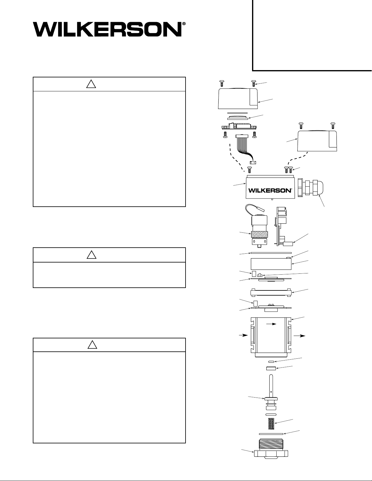
Control
Board
Housing
Intake / Exhaust
Valve
(2 Required)
Housing
Gasket
Filter
Upper
Diaphragm
Filter
Screw (2 Required)
For LCD Housing
LCD Housing
LCD Cover
Standard
Housing
Screw (3 Required)
For Control
Board Housing
Strain Relief
Standard
or LCD
Control
Board
O-Ring
Body Cap
Restrictor
Mid-Plate
WARNING
!
FAILURE OR IMPROPER SELECTION OR IMPROPER USE OF THE
PRODUCTS AND/OR SYSTEMS DESCRIBED HEREIN OR RELATED
ITEMS CAN CAUSE DEATH, PERSONAL INJURY AND PROPERTY
DAMAGE.
This document and other information from The Company, its subsidiaries
and authorized distributors provide product and/or system options for further
investigation by users having technical expertise. It is important that you
analyze all aspects of your application, including consequences of any
failure and review the information concerning the product or systems in the
current product catalog. Due to the variety of operating conditions and
applications for these products or systems, the user, through its own
analysis and testing, is solely responsible for making the final selection of
the products and systems and assuring that all performance, safety and
warning requirements of the application are met.
The products described herein, including without limitation, product features,
specifications, designs, availability and pricing, are subject to change by
The Company and its subsidiaries at any time without notice.
EXTRA COPIES OF THESE INSTRUCTIONS ARE AVAILABLE FOR
INCLUSION IN EQUIPMENT / MAINTENANCE MANUALS THAT UTILIZE
THESE PRODUCTS. CONTACT YOUR LOCAL REPRESENTATIVE.
Lower
Diaphragm
Inlet Port
Valve Stem
and Base
Bottom
Plug
Body
Outlet
Port
O-Ring
Insert
Spring
O-Ring
Page 2
Description
The ERl and ER2 are high flow electro-pneumatic regulators
capable of delivering accurate pressures over a wide range of
flows. The units have a variety of port sizes, ranging from 1/4
inch to 3/4 inch NPT and “G” series threads and use the
convenient Wilkerson 18/28 series modular mounting. The ER
series consists of an integral system of two control valves and
feedback transducer to provide closed-loop control. In addition
the units come with an optional LCD display that displays the
outlet pressure in psig or bar.
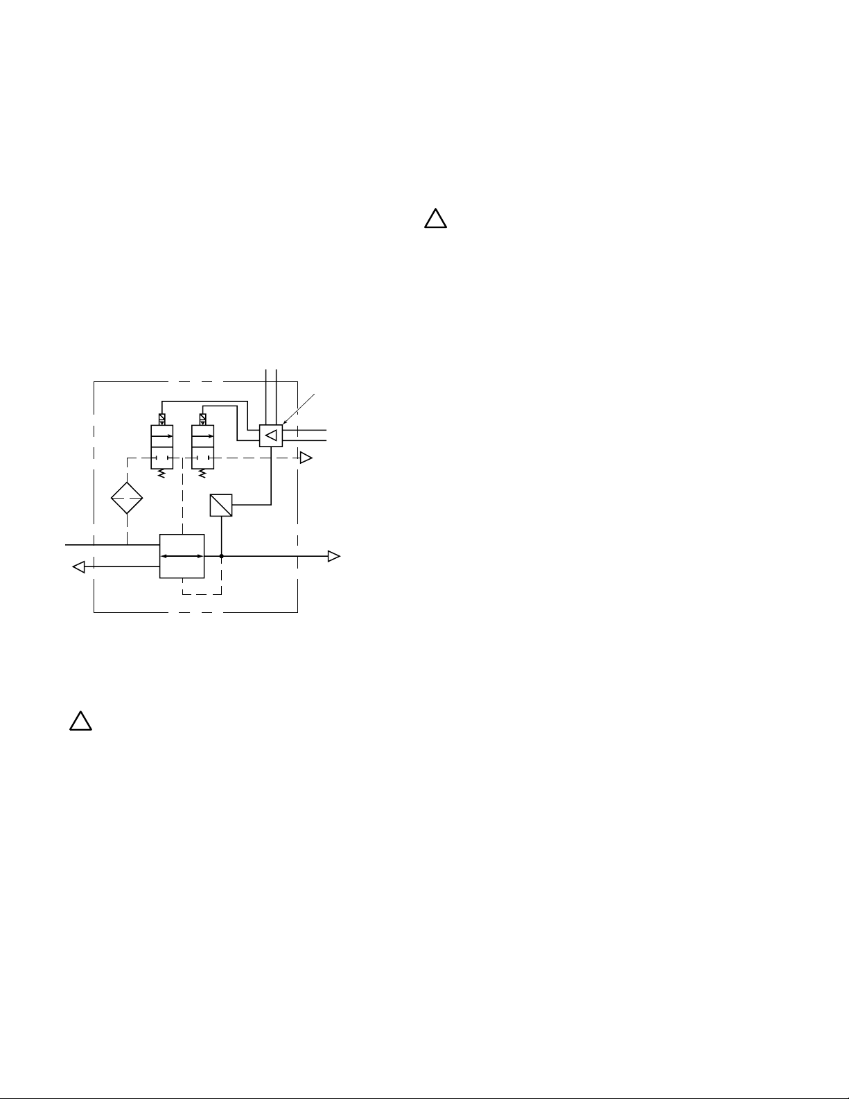
The ER series regulators are controlled by either a 0–10 VDC
or 4–20 mA external input signal, or by internal adjustment for
stand- alone operation. The control signal is compared to the
output signal of the internal pressure sensor and the regulator
adjusts the pressure accordingly. The pressure sensor signal
is also an output of 0–10 VDC for external monitoring.
Powe r
Supply
12–28 VDC
+–
Comparator /
Controller
Command
Signal
0–10 VDC
4–20 mA
E
P
Sensor
IN
OUT
Installation
Mechanical Installation
!
1. Refer to the WARNING above.
2. Do not install until you have read the entire product
information sheet.
3. Minimum inlet pressure ............................. 20 psig (1.4 bar)
Maximum inlet pressure ........................ 150 psig (10.3 bar)
Minimum temperature ..................................... 40°F (4.4°C)
Maximum temperature ................................ 125°F (51.6°C)
4. Prior to installation, ensure that the pressure in the line
where this product is to be connected is at atmospheric
pressure 0 psig (0 bar).
5. Install a quality Wilkerson filter upstream of the unit for
maximum trouble free operation.
6. Install with the air flow in the same direction as the arrow on
the unit. DO NOT restrict the air flow with undersize piping
or fittings, unless maximum flow is not required.
Electrical Connection
Since the same control board is used for all control signal options
(Figure 3A)
board must be configured for each particular application by
positioning the jumpers correctly and wiring correctly. This is a
very important step to ensure optimum performance.
Determine what signal you will be using to control the regulator
and follow the instructions for that application. The control
board must be configured and wired accordingly.
to provide maximum flexibility at minimum cost, the
!
Caution: Improper wiring may result in damage to the unit.
To configure the unit for the desired option, and to connect the
external wires to unit, remove the housing by removing the two
screws on top of the unit
off and lay it to one side, making sure not to damage the ribbon
cable that connects the control board to the LCD board.
The jumpers should be configured correctly from the
factory for the configuration ordered and will only need to be
changed if once the unit is received, the user decides on
different control signal, pressure display or pressure range.
(Refer to Figure 2)
Option #1 Sensor feedback signal
Internal sensor ................................. Jumper on position #5
Option #2 LCD display mode
a. psig............................................... Jumper on position #4
b. bar ................................................ Jumper off position #4
NOTE: If using bar option, be careful not to lose jumper.
Option #3 Control signal
a. 0–10 VDC .................................... Jumper on position #1
b. Internal control ............................. Jumper on position #2
c. 4–20 mA ....................................... Jumper on position #3
NOTE: Only one control signal at a time can be used.
Option #4 Pressure Range
Each control board has two pressure ranges available and
can be selected by the Jumper on position #7
The high range board can be configured for either:
a. 0–90 psig (0–6 bar) .....................Jumper on position #7
b. 0–125 psig (0–8,6 bar) ................Jumper off position #7
The low range board can be configured for either:
a. 0–30 psig (0–2 bar) .....................Jumper on position #7
b. 0–60 psig (0–4 bar) .....................Jumper off position #7
First feed the cable through the strain relief provided and remove
the retaining nut for the strain relief. Now feed the wires through
the hole in the control board housing, slide the retaining nut over
the wires and secure the strain relief to the housing making sure
to have the required amount of wire to connect them to the
terminal block. Once this is completed you can connect the wires
to the terminal block as the following describes.
Now, with the unit configured to the desired options, the
external electrical connection of the unit can be done. This is
accomplished by securing the wires directly to the control
board terminal block on the upper right hand side of the unit
(Figure 3)
required number of wires for your application be used to
connect the unit if using an external control and monitor signal.
The shield should be connected to the supply ground and not
to the unit. If using the internal control, only a supply voltage
will be required, although the monitor signal can be used.
. It is recommended that a shielded cable with the
(Figure 4)
. Carefully lift the housing
or
or
or
or
Page 3

ON PSIG / OFF Bar
Position #4
(For LCD Units Only)
Position #5
Internal Sensor
Position #6
(Not Used)
Position #7
Range Selection
Position #3
4–20 mA Control
Position #2
INTERNAL Control
Position #1
0–10 VDC Control
Position #5
0–10 VDC
Control Signal
Position #6
4–20 mA
Control Signal
Position #4
Not Used
Position #3
0–10 VDC
Monitor Signal
Position #2
Common
Ground (-)
Position #1
VDC Supply (+)
Positive Pole
Figure 3 – Terminal Block
Figure 2 – Jumper Connections
If using an external control circuit, connect the wires to
the appropriate terminals as follows:
(Refer to Figure 3)
Control signal:
- If using a 0–10 VDC control signal, connect the control wire
to position #5.
- If using a 4–20mA control signal, connect control wire to
position #6.
Monitor signal: (If used)
- Connect the external monitor feedback to position #3, this
outputs a 0–10 VDC that corresponds to a 1 VDC per 10%
of range.
Supply voltage and common ground:
- Connect the supply voltage positive pole (+) to position #1.
- Connect the common ground (–) for supply, control and
monitor signals to position #2.
If using the internal resistor control, wire the unit as follows:
Monitor signal: If monitor signal is not required, no
connection is required.
- Connect the external monitor feedback to position #3, this
outputs a 0–10 VDC that corresponds to a 1 VDC per 10%
of range.
Supply voltage and common ground:
- Connect the supply voltage positive pole (+) to position #1.
- Connect the common ground (–) for supply, and monitor
signals to position #2.
!
CAUTION: Reversing the polarity of the supply signal my
result in damage to the board.
Once the wires are properly located, secure the wires in the
terminal block and tighten the strain relief to secure the wires
and provide protection from the environment.
PLC Control with 0 – 10 VDC
PLC
Power Supply (+)
12 – 28 VDC
Monitor Signal (+)
0 – 10 VDC (–)
Control Signal (+)
0 – 10 VDC (–)
PLC Control with 4 – 20 mA
(–)
PLC
Power Supply (+)
12 – 28 VDC
Monitor Signal (+)
0 – 10 VDC (–)
Control Signal (+)
4 – 20 mA (–)
Internal Potentiometer
Power Supply (+)
12 – 28 VDC
Monitor Signal (+)
0 – 10 VDC (–)
(–)
(–)
Figure 3A – Control Options
Pressure Display
Internal Pressure Control
Internal Pressure Control
Internal Pressure Control
and
1
2
E
3
4
5
6
Pressure Display
1
2
3
4
5
6
Pressure Display
1
2
3
4
5
6
P
and
I
P
and
E
P
Page 4

Zero and Span Adjustment
The zero and span adjustment was set at the factory and should
not require any further adjustment. If the zero and span do need
to be adjusted, energize the unit. Input 0 VDC to the control
signal and using a volt meter, measure the output on the
position #3 of the terminal block. The output should be -0.01 to 0
VDC. If not turn the zero potentiometer
output is correct. To adjust the span, attach an external
pressure gauge and apply 8 VDC to the control signal. Then
adjust the span potentiometer
(Figure 4)
80% of the range selected [i.e. 24 psig (1,6 bar) for 0–30 psig
(0–2 bar), 48 psig (3,3 bar) for 0–60 psig (0–4 bar), 72 psig (4,9
bar) for 0–90 psig (0–6 bar), 100 psig (6,8 bar) for 0–125 psig
(0–8,6 bar)]. This completes the zero and span adjustments.
Now carefully replace the cover. It can be installed in two
positions, 180 degrees apart from each other. Then replace
the two securing screws.
The unit is now ready for operation. Supply pressure and
power to the unit can be turned on.
(Figure 4)
until the
until the P2 pressure is
Exhaust
Valve
Connector
Zero
Adjustment
Potentiometer
Jumpers
Cover
Intake Valve
Connector
Span
Adjustment
Potentiometer
Terminal
Block
LCD Board
Ribbon Cable
Connector
Control
Board
Housing
Body Cap
Mid Plate
Body
Bottom Plug
Figure 4
If Internally Controlled (On LCD Units Only)
To adjust the pressure, pry the internal adjustment cap off.
With power and pressure to the unit turn the adjustment screw
(Figure 5)
the cap.
until the desired pressure is achieved then replace
Internal
Pressure
Adjustment
Screw
Figure 5
Page 5

Maintenance
1.
DEPRESSURIZE THE AIR LINE PRIOR TO ATTEMPTING ANY
!
SERVICE TO THE UNIT! IT IS ALSO RECOMMENDED THAT
POWER TO THE UNIT BE DISCONNECTED PRIOR TO SERVICING.
2. Main Valve: Remove bottom plug, valve assembly and valve spring.
Inspect all the seals and components for damage and replace as
required. Clean all seals and components with soft cloth and lightly
lubricate the valve O-ring, bottom plug O-ring and valve stem with
MAGNALUBE-G lubricant and reassemble in reverse order.
3. LCD Display: Remove the two screws from the LCD cover and
carefully remove the cover. Turning the cover over, remove the two
screws inside that retain the LCD board to the cover and lift out the
LCD board. Unplug the display board from the ribbon cable. If
defective replace with a new LCD board and re-connect the ribbon
cable. Making sure the LCD lens and seal are in place, replace the
LCD board in the cap and secure with the two screws. Replace the
cover back on the unit and secure with the two screws.
4. Control Board: If unit is an LCD type, remove the LCD display
board from the cap as described in step #3 and unplug the ribbon
cable from the LCD board. Now unscrew the three screws that retain
the control board housing and unplug the valves from the back of the
control board. Carefully lift the housing with the control board still
inside. Remove the control board from the bottom of the housing and
replace with the new control board. Reassemble in reverse order.
5.
Valve Replacement: The electronic valves cannot be serviced
internally. If failure occurs, replace the valve. To replace the valves,
remove the housing as described in step #4 above. Once the housing
is removed, unscrew the defective valve from the cap. Making sure to
replace with correct valve [3 position connector for intake valve and 2
position connector for the exhaust valve
down until it seals on the base of the valve seal. Reassemble the
control board and cap as described in steps #3 and #4.
6. Diaphragm, Mid-plate and Regulator Cap: Remove the control
board and housing as described in step #4 and remove the exhaust
valve. Now remove the two screws that secure the cap to the
regulator body. Lift the cap from the body. Remove the upper and
lower diaphragms, noting which one is upper and lower, from the
mid-plate. Examine the diaphragms and relief seat in the lower
diaphragm for wear and tears and replace as required. Replace the
filter in the mid plate. Clean all surfaces and components with a soft
cloth and reassemble in reverse order.
(Figure 6)
], screw the valve
NOTE:
Intake Valve
Exhaust Valve
Any time the mid-plate is removed, replace the internal
filters (see exploded view for locations). One is in the cap
for the exhaust, one is in the mid-plate for the intake.
Figure 6
Page 6

Inches
G
millimeters
Dimensions
Models A B C D E F G
A
B
E
DC
Front View Side View
F
Repair Kits and Replacement Parts
Control Board LCD 30/60 psig (2.0/4.0 bar) ..... ERP-95-786
Control Board LCD 90/125 psig (6.0/8.6 bar) ... ERP-95-788
Control Board, STD, 30/60 psig (2.0/4.0 bar) ... ERP-95-798
Control Board, STD, 90/125 psig (6.0/8.6 bar) . ERP-95-799
LCD Board and Ribbon ..................................... ERP-95-787
Intake Valve ....................................................... ERP-95-790
Exhaust Valve .................................................... ERP-95-791
Diaphragm Kit, ER1 ........................................... ERP-95-792
Diaphragm Kit, ER2 ........................................... ERP-95-793
Bottom Valve and Valve Spring ........................ ERP-95-794
ER1 6.31 4.71 2.35 .79 1.79 2.35 1.20
160 120 60 20 45 60 30
ER2 6.31 4.71 2.88 .79 1.79 2.88 1.20
160 120 73 20 45 73 30
Troubleshooting
Unit Fails to Operate
1) Verify supply voltage
2) Verify control voltage
3) Intake valve or controller failure
4) Apply 12 VDC to valve and listen for slight
click indicating valve is working
5) Replace control board
Specifications
Min Max Nom Units
Supply Voltage 12 28 — VDC
Supply Current — 250 80 mA
Control Signal
Voltage 0 10 — VDC
Impedance — 200 KOHM
Current 4 20 — mA
Impedance — 600 OHM
Internal — — — —
Monitor Output 0 10 — VDC
Overall Accuracy — — 1.5% SCALE
Supply Pressure 20 150 — psig
(1.4) (10.3) — (bar)
Output Pressure 0 30/60/90/125 psig
(0.0) (2/4/6/8.6) (bar)
Temperature 40 125 — °F
(4.4) (51.6) — (°C)
Flow Rate [150 psig (10 bar) inlet and 90 psig (6 bar)
outlet with a 5 psid (0.3 bar)]
ER1 ................................................................ 200 SCFM (94.3 dm3/s)
ER2 ................................................................ 200 SCFM (94.3 dm3/s)
Note: For optimum operation, inlet pressure should be a minimum
of 15 psig (1.0 bar) above the controlled pressure.
Unit Remains Pressurized
1) Verify control voltage
2) Exhaust valve or controller failure
3) Apply 12 VDC to valve and listen for
slight click indicating valve is working
4) Replace control board
LCD Fails to Display Pressure
1) Verify supply voltage
2) Verify that ribbon cable is secure on both ends
3)
Have dealer check LCD board and replace if necessary
4) Replace control board
Unit Has Constant Leak or is Unstable
1) Inspect and clean bottom valve seals and
lubricate bottom valve
2) Inspect and clean diaphragms
 Loading...