

Page 1
Pneumatic Division
3
2
1
4
!
!
!
Richland, Michigan 49083
269-629-5000
Installation & Service Instructions
2R210
40mm & 60mm
Proportional Regulator
ISSUED: September, 2008
Supersedes: May, 2005
Doc. # 2R210, EN #080690, Rev 2
WARNING
To avoid unpredictable system behavior that can cause personal injury
and property damage:
• Disconnect electrical supply (when necessary) before installation,
servicing, or conversion.
• Disconnectairsupplyanddepressurizeallairlinesconnectedtothis
product before installation, servicing, or conversion.
• Operate within the manufacturer’sspecied pressure,temperature,
and other conditions listed in these instructions.
• Medium must be moisture-free if ambient temperature is below
freezing.
• Serviceaccordingtoprocedureslistedintheseinstructions.
• Installation, service, and conversion of these products must be
performed by knowledgeable personnel who understand how
pneumatic products are to be applied.
• Afterinstallation,servicing,orconversion,airandelectricalsupplies
(when necessary) should beconnected andthe producttested for
proper function and leakage. If audible leakage is present, or the
product does not operate properly, do not put into use.
• Warningsandspecicationsontheproductshouldnotbecoveredby
paint, etc. If masking is not possible, contact your local representative
for replacement labels.
WARNING
Product rupture can cause serious injury.
Do not connect regulator to bottled gas.
at all times (parameter 14).
Mounting Position: Preferably vertical, with the cable gland on
top.
Electronics
Supply Voltage: ................................................24 VDC +/- 10%
Power Consumption: .......................................................1.1 W
Current Consumption: .................... Max. 200 mA with no load
Control Signals: The electronic pressure regulator can be
externally controlled through an analog control signal of 0-10 V,
adjustable to 4-20 mA via parameter 4.
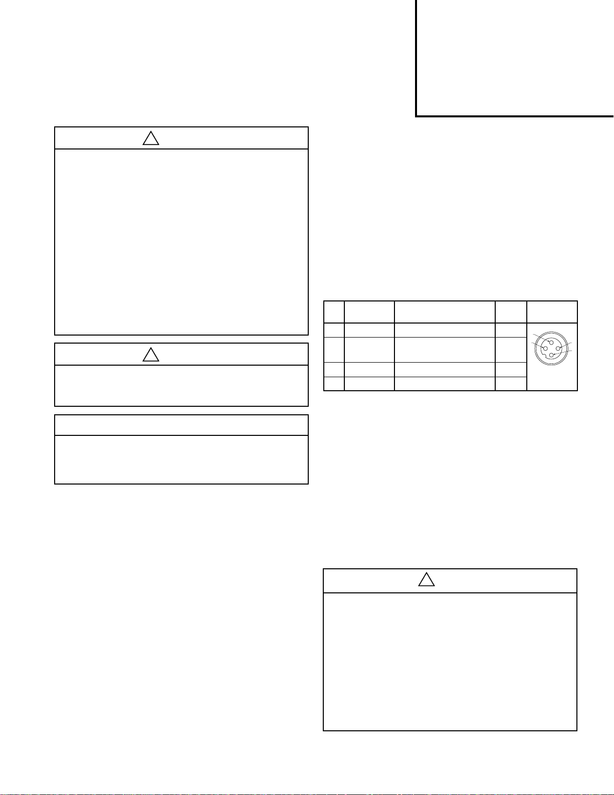
Connections: .............................. Central M12 connector 4-pole
The electrical connections are as follows:
Pin
Function Description Color
No.
1 24 V Supply Brown
0 to 10 V or
2
4 to 20mA
3 0 V (GND) Supply Blue
4 24 V Alarm Output Signal Black
Control Signal Ri = 100k
W White
Do not exceed maximum primary pressure rating.
Dead Band: The dead band is preset at 1.3% F.S.*, adjustable
via parameter 13.
as indicated on the label, can be changed through the software
Safety Guide
For more complete information on recommended application
guidelines, see the Safety Guide section of Pneumatic Division
catalogs or you can download the Pneumatic Division Safety
Guide at: www.parker.com/safety
Introduction
Follow these instructions when installing, operating, or servicing
the product.
Technical Information
These products are intended for use in general purpose
Accuracy: .............................................Linearity: = < 0.3% F.S.*
Proportional Band: The proportional band is preset at 10% F.S.*
Fail-safe Operation: After interrupting the power supply voltage,
the present output pressure is maintained at approximately
the same level. After switching the power supply on again, the
pressure can be adjusted immediately by giving a new control
signal.
Full Exhaust:
Complete exhaust of the regulator is defined as
P2 ≤ 1% F.S.*
Degree of Protection: .........................................................IP65
* Full Scale
compressed air systems only.
Pneumatics
Working Media: Compressed air or inert gasses, filtered to 40µ.
Operating Pressure:
Max. Operating Pressure ...... 2 bar unit ............. 3 bar (43.5 PSI)
10 bar unit ...... 10.5 bar (152 PSI)
Min. Operating Pressure .......... P2 Pressure + 0.5 bar (7.3 PSI)
Pressure Control Range: Available in two pressure ranges,
0-2 bar (0-29 PSI) or 0-10 bar (0-145 PSI). Pressure range can be
changed through the software at all times. (parameter 19)
Temperature Range: .....................32°F to 122°F (0°C to 50°C)
Weight: ............................................................................10 oz.
Air Consumption: No consumption in stable regulated situation.
Display: The regulator is provided with a digital display, indicating
the output pressure, either in PSI or bar. The factory setting is
FAILURE OR IMPROPER SELECTION OR IMPROPER USE OF THE
PRODUCTS AND/OR SYSTEMS DESCRIBED HEREIN OR RELATED ITEMS
CAN CAUSE DEATH, PERSONAL INJURY AND PROPERTY DAMAGE.
This document and other information from Parker Hannifin Corporation, its
subsidiaries and authorized distributors provide product and/or system options
for further investigation by users having technical expertise. It is important
that you analyze all aspects of your application, including consequences of
any failure and review the information concerning the product or systems
in the current product catalog. Due to the variety of operating conditions
and applications for these products or systems, the user, through its own
analysis and testing, is solely responsible for making the final selection of the
products and systems and assuring that all performance, safety and warning
requirements of the application are met.
The products described herein, including without limitation, product features,
specifications, designs, availability and pricing, are subject to change by Parker
Hannifin Corporation and its subsidiaries at any time without notice.
EXTRA COPIES OF THESE INSTRUCTIONS ARE AVAILABLE FOR INCLUSION
IN EQUIPMENT / MAINTENA NCE MANUALS THAT UTILIZE THESE PRODUCTS.
CONTACT YOUR LOCAL REPRESENTATIVE.
WARNING
Page 2
40mm & 60mm Proportional Regulator 2R210
or
or
or
or
Installation
1. Place muffler in Port 3
2. Connect the device to the Air Supply Port 1 and 2.
3. Connect Female M12 Connector on the Male Connector of
the device.
4. Apply 24V = (10 second time delay for initialization of
unit).
5. Air Supply to Port 1.
6. Give desired Set Point Signal.
7. Secondary Pressure will now be displayed.
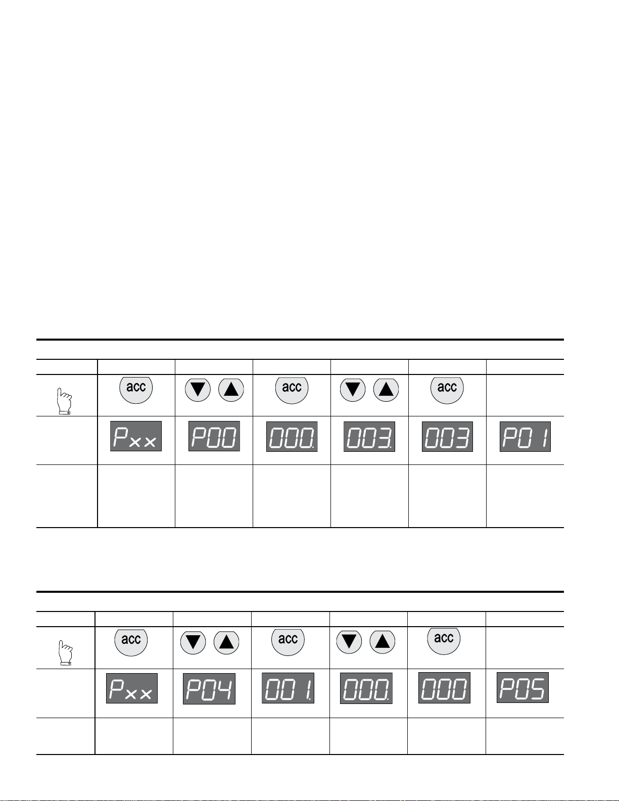
How to Change Parameters
Pressing the Accept key for 3 to 6 seconds, will activate parameter
change mode. The user can then select the parameters by pressing
up or down key (display will show Pxx). When parameter number is
correct, pressing accept again will enter parameter number (display
will show parameter value).
Pressing the up or down key will change the parameter itself
(display will flash indicating parameter editing mode). Pressing
the accept key will accept the new parameter value (all digits will
flash while being accepted).
After releasing all keys, the next parameter number will be
presented on the display (you may step to the next parameter).
When no key is pressed, after 3 seconds the display will show
the actual output pressure.
Only parameter numbers 0, 4, 9, 14, 18, 19, 20, 12, 13, and 21
are accessible to edit. All other parameters are fixed.
Manual Mode
When keys DOWN and UP are pressed during startup,
(connecting to the 24 V pow er supply) man ual mode is activated.
This means that the user is able to in/decrease the output
pressure of the regulator, by pressing the UP or DOWN key.
During this action the display will blink, indicating that the manual
mode is activated.
Back to Factory Setting
After start up. (Power is on)
Parameter 0 = 3
Entering this value in parameter 0 will store the calibrated factory data into the working parameters. (Default calibration data is
used)
Parameter Number 0 – Reset Back to Factory Settings
Step 1 2 3 4 5
Press
3-6 seconds
Until
Display
Reads
Flashing Decimal Flashing Decimal Flashing
Description
Accesses
changeable
parameters.
Accesses
parameter no. 0.
Displays current
parameter value.
Edits parameter.
3 = standard
factory settings. If
other than 3, use
Up or Down
Arrow and accept 3
Accepts and saves
new parameter
setting.
Set Control Signal
The unit is factory set for 0-10 V control signal. If 4-20 mA control signal is required, change parameter 4.
Parameter Number 4 – Set Control Signal in Volts or Milliamps
Step 1 2 3 4 5
Press
Sequences to next
parameter.
Until
Display
Reads
Description
3-6 seconds
Accesses
changeable
parameters.
Accesses
parameter no. 4.
Flashing Decimal Flashing Decimal Flashing
Displays current
parameter value.
1 = V, 0 = mA
Edits parameter.
Accepts and saves
new parameter
setting.
2
Sequences to next
parameter.
Page 3
40mm & 60mm Proportional Regulator 2R210
or
or
or
or
or
or
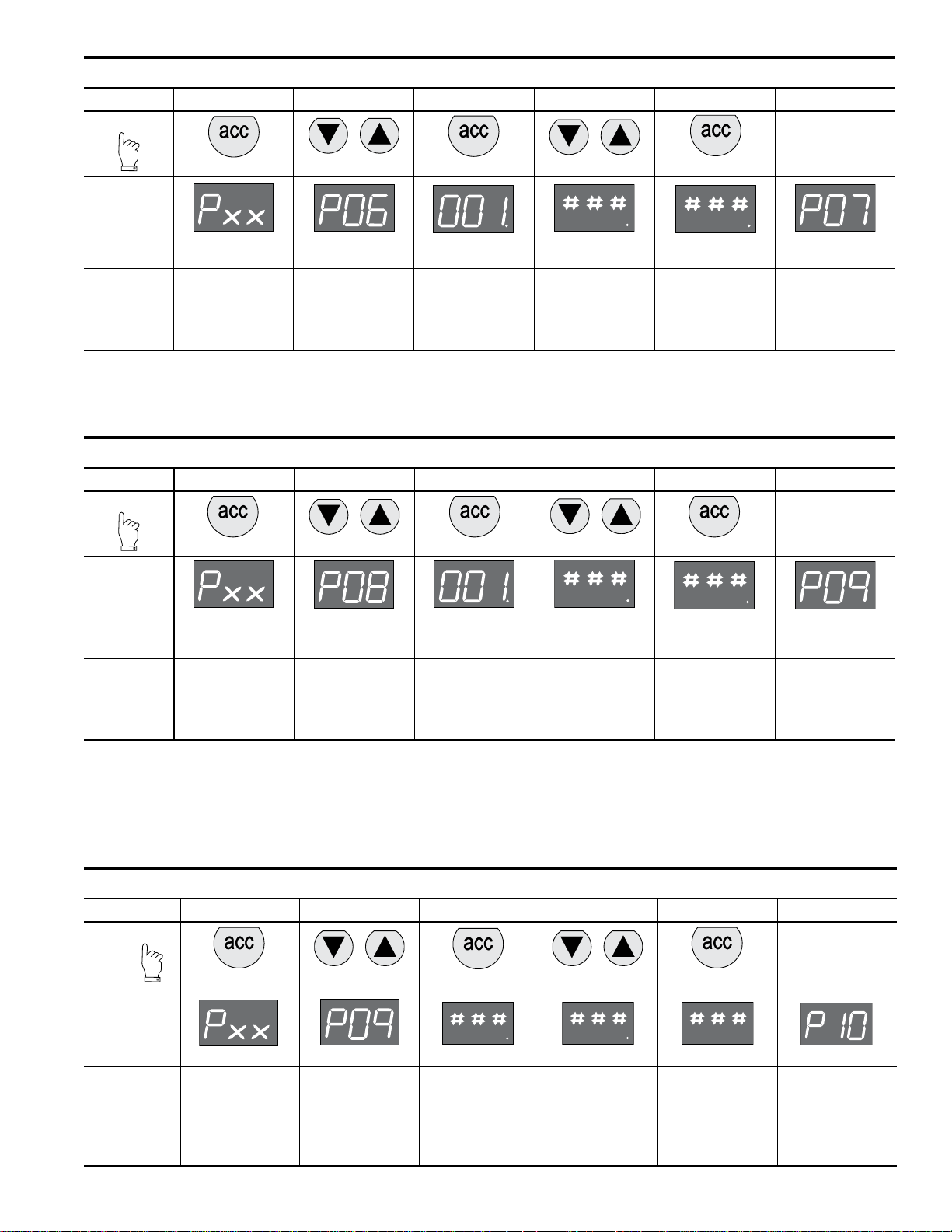
Parameter Number 6 – Set Output Signal
Step 1 2 3 4 5
Press
3-6 seconds
Until
Display
Reads
Description
Accesses
changeable
parameters.
Accesses
parameter no. 6.
Flashing Decimal
Displays current
parameter value.
1 = m factory
default for P3H with
analog options
Flashing Decimal
(Value 0, 1 or 2) Flashing
Edits parameter.
0 = digital
(NPN or PNP)
1 = analog 0..10V
2 = analog 4..20 mA
Accepts and saves
new parameter
setting.
Sequences to next
parameter.
Parameter Number 8 – Adjust Span Analog Output Signal
Step 1 2 3 4 5
Press
3-6 seconds
Until
Display
Reads
Description
Accesses
changeable
parameters.
Accesses
parameter no. 8.
Flashing Decimal
(For 2 bar versions
value = 92)
Displays current
parameter value. Edits parameter.
Flashing Decimal
(Value between
0 and 130) Flashing
Accepts and saves
new parameter
setting and
implements the new
analog signal span.
Sequences to next
parameter.
Adjust Digital Display
If necessary, adjustments can be made to the digital display when using an external pressure sensor.
ParameterNumber9–AdjustDigitalDisplayValue(PressureCalibration)
Step 1 2 3 4 5
Press
3-6 seconds
Until Display
Description
Reads
Accesses
changeable
parameters.
Accesses
parameter no. 9.
Flashing Decimal Flashing Decimal Flashing
Use up or down
arrows and accept
to adjust the
Displays current
digital display
display value if
using an external
pressure sensor.
Accepts and saves
new parameter
setting.
3
Sequences to next
parameter.
Page 4

40mm & 60mm Proportional Regulator 2R210
or
or
or
or
or
or
Set Pressure Scale
Units with NPT port threads are supplied with a factory set PSI pressure scale. Use parameter 14 to change scale to bar.
Parameter Number 14 – Set Pressure Scale in PSI or bar
Step 1 2 3 4 5
Press
3-6 seconds
Until
Display
Reads
Flashing Decimal Flashing Decimal Flashing
Description
Accesses
changeable
parameters.
Accesses
parameter no. 14.
Displays current
parameter value.
1 = PSI, 0 = bar
Edits parameter.
Accepts and saves
new parameter
setting.
Sequences to next
parameter.
Preset Minimum Pressure
If there is a need for a pre-set minimum pressure, use parameter 18. (Note: preset pressure is affected by % P19.)
Parameter Number 18 – Set Minimum Preset Pressure
Step 1 2 3 4 5
Press
3-6 seconds
Until
Display
Reads
Description
Accesses
changeable
parameters.
Accesses
parameter no.
18.
Flashing Decimal
Displays current
Incremental value is:
2 bar unit: x 2 mbar x % P19
10 bar unit: x 10 mbar x % P19
parameter value.
Flashing Decimal
(value between
0 and 200)
Edits parameter.
Flashing
Accepts and
saves new
parameter
setting.
Sequences to
next parameter.
Set Pressure Correction
Pressure correction allows the user to set a maximum pressure as a percentage of secondary pressure F.S.
Example: If F.S. is 10 bar, set parameter 19 to 50 for maximum preset pressure of 5 bar.
Pressure correction also affects the minimum preset pressure in parameter 18.
Example: If F.S. is 10 bar and parameter 18 is set to a value of 100 (1 bar), and parameter 19 is set to 50%, then the actual
minimum preset pressure seen is 0.5 bar.
Parameter Number 19 – Set Maximum Preset Pressure
Step 1 2 3 4 5
Press
3-6 seconds
Until
Display
Reads
Description
Accesses
changeable
parameters.
Accesses
parameter no. 19.
Flashing Decimal
Flashing Decimal
Displays current
parameter value.
Incremental
value is: % of F.S. Edits parameter.
(value between
0 and 100)
4
Flashing
Accepts and saves
new parameter
setting.
Sequences to next
parameter.
Page 5

40mm & 60mm Proportional Regulator 2R210
or
or
or
or
Behavior Control
The regulation speed of the pressure regulator can be modified by means of one parameter. (P 20)
The value in this parameter has a range from 0-5. A higher value indicates slower regulation speed, but will be more stable.
Parameter Number 20 – Set Behavior Control
Step 1 2 3 4 5
Press
3-6 seconds
Until
Display
Reads
Flashing Decimal
Description
Accesses
changeable
parameters.
* When the value 0 is entered, you are able to create your own custom settings true parameters 12, 13 and 21.
Accesses
parameter
no. 20.
Displays current
parameter value.
Flashing Decimal
(value between 0
and 5)
Edits parameter
0 = custom set*
1 = fastest (narrow
proportional band)
2 = fast,
3 = normal,
4 = slow,
5 = slowest
(proportional band
is broad)
Flashing
Accepts and saves
new parameter
setting.
Sequences to next
parameter.
Fine Settings
Set Proportional Band
Proportional band is used for setting the reaction sensitivity of the regulator. The displayed value is X 10 mbar and has a range
between 50 (0.5 bar) and 250 (2.5 bar).
ParameterNumber12–SetProportionalBand(P20MustbeSetto0)
Step 1 2 3 4 5
Press
3-6 seconds
Until
Display
Reads
Description
Accesses
changeable
parameters.
Accesses
parameter no. 12.
Flashing Decimal
Displays current
parameter value.
Incremental
value is:
x 10 mbar
5
Flashing Decimal
(value between
50 and 250)
Edits parameter.
Flashing
Accepts and saves
new parameter
setting.
Sequences to next
parameter.
Page 6

40mm & 60mm Proportional Regulator 2R210
or
or
or
or
or
Set Deadband
Deadband is the minimum limit of accuracy at which the regulator is set for normal operation. The displayed value is X 10 mbar
and has a range between 4 (40 mbar) and 40 (400 mbar).
ParameterNumber13–SetDeadband(P20MustbeSetto0)
Step 1 2 3 4 5
Press
3-6 seconds
Until
Display
Reads
Description
Accesses
changeable
parameters.
Accesses
parameter no. 13.
Flashing Decimal
Displays current
parameter value.
Incremental
value is
x 10 mbar
Flashing Decimal
(value between
4 and 40)
Edits parameter.
Flashing
Accepts and saves
new parameter
setting.
Sequences to next
parameter.
Proportional Effect
Sets the speed at which the regulator adjusts either filling or exhausting. The displayed value has a range between 5 (fastest
regulation) and 100 (slowest regulation).
ParameterNumber21–SetProportionalEffect(P20MustbeSetto0)
Step 1 2 3 4 5
Press
3-6 seconds
Until
Display
Reads
Description
Accesses
changeable
parameters.
Accesses
parameter no. 21.
Flashing Decimal
Displays current
parameter value.
Flashing Decimal
(value between
5 and 100)
Edits parameter.
5 = fastest
regulation
100 = slowest
regulation.
Flashing
Accepts and saves
new parameter
setting.
Sequences to next
parameter.
Parameter Number 39 – Displays Current Software Version
Step 1 2 3
Press
3-6 seconds
Until
Display
Reads
Flashing Decimal
Displays current
parameter value.
XXX = current
software version
Description
Accesses
changeable
parameters.
Accesses
parameter no. 39.
6
Page 7

40mm & 60mm Proportional Regulator 2R210
Problem Possible Reason Solution
Display will not light up No 24 volts power supply Check if the wiring is connected according to
the schematic wiring diagram
Unit will not, or not correctly respond to
given setpoint
Display shows NoP. Unit detects that required output pressure
Unit behavior is not considered normal Faulty settings made in the parameters Reset the unit to factory settings by using the
Desired pressure can not be reached Setpoint value to low
Wrong current applied ( I.e. Volt instead of
mA or mA instead of Volt
Setpoint signal is not stable enough Stabilize setpoint signal input
is higher than the supplied pressure
No inlet pressure at all Connect port 1 to the supply pressure
Change setpoint current or re configure the
setpoint current through the software by
changing parameter 4
Check wiring if the setpoint signal lead is
connected to the right pin within the male M12
connector ( should be pin 2)
Adjust the inlet pressure to a higher value,
preferably 0,5 bar higher than requested output
pressure
Give lower setpoint value which corresponds to
a output pressure lower than the inlet pressure
green key function under parameter 0
Increase setpoint value
Pre-set pressure limit has been changed
to a lower max. outlet pressure
Supply pressure is to low Increase supply pressure
Secondary side stays pressurized Setpoint value is higher than 0,1 Volt
Pre-set pressure has been enabled to a
certain pressure
Display shows unrealistic value Display maybe configured in the wrong
value ( bar instead of psi)
Unit response time too slow or too quick Volume behind the unit is either too big or
too small
Unit gives too much overshoot Relation between volume and response
me is out of balance
Unit is adjusting/regulating constantly Air leakage in the system behind the unit
Constant changing volume behind the unit
“Deadband “area is set too small
Can not enter software through touchpad Unit is currently working/processing Make sure that the unit is in steady state while
Activating time is too short Hold the accept button for at least 3 seconds
Display indicates ‘OL’ Wiring not according to diagram (24 volt
connected on the setpoint connection pin)
Wrong setpoint value given in relation to
programmed setpoint value acceptance
Any other problem Please consult factory
Change max. outlet pressure back to required
pressure by changing parameter 19
Lower your setpoint value, preferably to 0 Volts
Reset parameter 18 to 0
Check through parameter 14, if the display
value is set on either psi or bar, if necessary
change it to the required setting
Adjust the regulating speed of the unit through
parameter 20
Adjust response time to a higher value through
parameter 20, to achieve more accurate
behavior
Resolve leakage
Unit needs to regulate to keep required pres-
sure at the same level
Try to minimize the volume changes
Enlarge deadband setting through parameter
13 in the software ( parameter 20 has to be set
to 0 before changing parameter 13)
activating the software
Rewire so that on the setpoint connection pin
will be either 0-10v or 4-20mA
Change over setpoint value to either V or mA
or Reprogram the unit to the correct setpoint
value via parameter 4
7
Page 8

40mm & 60mm Proportional Regulator 2R210
0.55
(14)
4.49
(114)
1.85
(47)
1.18
(30)
1/4 1/4
1/4
Ø 0.87
(22)
0.85
(21.5)
0.08
(2)
0.35
(9)
0.83
(21)
0.83
(21)
Ø 0.22
(5.5)
4 Pin M12 Connector
0.53
(13.5)
0.35
(9)
2.19
(55.5)
80°
4.49
(114)
1.85
(47)
1/4
1/4
1/4
0.59
(15)
1.65
(42)
Ø 0.87
(22)
0.83
(21)
1.83
(46.6)
1/4(3x)
1.65
(42)
21
(0.83)
0.09
(2.3)
DIN-Rail
Clamp
4.49
(114)
Ø 0.87
(22)
0.35
(9)
4 Pin M12 Connector
0.56
(14.3)
6.62
(168.1)
2.46
(62.6)
4.12
(104.6)
2.50
(63.5)
1.18
(30)
2.95
(75)
1.48
(37.5)
1/2” Port
1.18
(30)
2.36
(60)
.59
(15)
.59
(15)
.59
(15)
.98
(25)
1.18
(30)
1.42
(36)
1.77
(45)
.47
(12)
2.20
(56)
1.02
(26)
2.05
(52)
1.57
(40)
2.05
(52)
3.31
(84)
3.94
(100)
Ø .28
(7)
4 Holes
Dimensions
40mm Bottom Exhaust Version
60mm Bottom Exhaust Version
Dimensionsareinmm(Inches)
Dimensionsareinmm(Inches)
Foot Bracket
DIN Rail Bracket
L Bracket
Foot Bracket
8
 Loading...