

Page 1

Page 2

Page 3

DESIGN, DEPLOYMENT
AND PERFORMANCE
OF 4G-LTE NETWORKS
Page 4

Page 5

DESIGN, DEPLOYMENT
AND PERFORMANCE
OF 4G-LTE NETWORKS
A PRACTICAL APPROACH
Ayman Elnashar
Emirates Integrated Telecomms Co., UAE
Mohamed A. El-saidny
QUALCOMM Technologies, Inc., USA
Mahmoud R. Sherif
Emirates Integrated Telecomms Co., UAE
Page 6

This edition rst published 2014
© 2014 John Wiley & Sons, Ltd
Registered ofce
John Wiley & Sons Ltd, The Atrium, Southern Gate, Chichester, West Sussex, PO19 8SQ, United Kingdom
For details of our global editorial ofces, for customer services and for information about how to apply for
permission to reuse the copyright material in this book please see our website at www.wiley.com.
The right of the author to be identied as the author of this work has been asserted in accordance with the Copyright,
Designs and Patents Act 1988.
All rights reserved. No part of this publication may be reproduced, stored in a retrieval system, or transmitted, in any
form or by any means, electronic, mechanical, photocopying, recording or otherwise, except as permitted by the UK
Copyright, Designs and Patents Act 1988, without the prior permission of the publisher.
Wiley also publishes its books in a variety of electronic formats. Some content that appears in print may not be
available in electronic books.
Designations used by companies to distinguish their products are often claimed as trademarks. All brand names and
product names used in this book are trade names, service marks, trademarks or registered trademarks of their
respective owners. The publisher is not associated with any product or vendor mentioned in this book.
Limit of Liability/Disclaimer of Warranty: While the publisher and author have used their best efforts in preparing
this book, they make no representations or warranties with respect to the accuracy or completeness of the contents of
this book and specically disclaim any implied warranties of merchantability or tness for a particular purpose. It is
sold on the understanding that the publisher is not engaged in rendering professional services and neither the
publisher nor the author shall be liable for damages arising herefrom. If professional advice or other expert
assistance is required, the services of a competent professional should be sought.
Library of Congress Cataloging-in-Publication Data
Elnashar, Ayman.
Design, deployment and performance of 4G-LTE networks : A Practical Approach / Dr Ayman Elnashar,
Mr Mohamed A. El-saidny, Dr Mahmoud Sherif.
pages cm
Includes bibliographical references and index.
ISBN 978-1-118-68321-7 (hardback)
1. Wireless communication systems. 2. Mobile communication systems. I. Title.
TK5103.2.E48 2014
′
621.3845
6–dc23
2013037384
A catalogue record for this book is available from the British Library.
ISBN: 978-1-118-68321-7
Typeset in 10/12pt TimesLTStd by Laserwords Private Limited, Chennai, India
1 2014
Page 7

To my beloved kids Noursin, Amira, and Yousef. You’re the inspiration!
This book is dedicated to the memory of my father (God bless his soul) and also
my mother, who’s been a rock of stability throughout my life. This book is also
dedicated to my beloved wife whose consistent support and patience sustain me
still.
My sincerest appreciations for a lifetime career that has surpassed anything my
imagination could have conceived.
Ayman Elnashar
To my Family for all their continuous support. To my elder brother for his guidance
and motivation throughout the years. To my inspirational, intelligent, and beautiful
daughter, Hana.
Your work is going to ll a large part of your life, and the only way to be truly
satised is to do what you believe is great work. And the only way to do great
work is to love what you do. If you haven’t found it yet, keep looking. Don’t
settle. As with all matters of the heart, you’ll know when you nd it. – Steve Jobs
Mohamed A. El-saidny
This work would not have been possible without the consistent and full support of
my beloved family. To my beloved wife, Meram, to my intelligent, motivating, and
beautiful kids, Moustafa, Tasneem, and Omar. You are my inspiration.
To my Dad, my Mom (God bless her soul), my brother, and my entire family. Thank
you for all your support and encouragement.
There is no elevator to success. You have to take the stairs. – Unknown Author
Those who think they have found this elevator will end up falling down the elevator
shaft
Mahmoud R. Sherif
Page 8

Page 9

Contents
Authors’ Biographies xv
Preface xvii
Acknowledgments xix
Abbreviations and Acronyms xxi
1 LTE Network Architecture and Protocols 1
Ayman Elnashar and Mohamed A. El-saidny
1.1 Evolution of 3GPP Standards 2
1.1.1 3GPP Release 99 3
1.1.2 3GPP Release 4 3
1.1.3 3GPP Release 5 3
1.1.4 3GPP Release 6 4
1.1.5 3GPP Release 7 4
1.1.6 3GPP Release 8 5
1.1.7 3GPP Release 9 and Beyond 5
1.2 Radio Interface Techniques in 3GPP Systems 6
1.2.1 Frequency Division Multiple Access (FDMA) 6
1.2.2 Time Division Multiple Access (TDMA) 6
1.2.3 Code Division Multiple Access (CDMA) 7
1.2.4 Orthogonal Frequency Division Multiple Access (OFDMA) 7
1.3 Radio Access Mode Operations 7
1.3.1 Frequency Division Duplex (FDD) 8
1.3.2 Time Division Duplex (TDD) 8
1.4 Spectrum Allocation in UMTS and LTE 8
1.5 LTE Network Architecture 10
1.5.1 Evolved Packet System (EPS) 10
1.5.2 Evolved Packet Core (EPC) 11
1.5.3 Evolved Universal Terrestrial Radio Access Network (E-UTRAN) 13
1.5.4 LTE User Equipment 13
1.6 EPS Interfaces 14
1.6.1 S1-MME Interface 14
1.6.2 LTE-Uu Interface 15
1.6.3 S1-U Interface 17
1.6.4 S3 Interface (SGSN-MME) 18
Page 10

viii Contents
1.6.5 S4 (SGSN to SGW) 18
1.6.6 S5/S8 Interface 19
1.6.7 S6a (Diameter) 21
1.6.8 S6b Interface (Diameter) 21
1.6.9 S6d (Diameter) 22
1.6.10 S9 Interface (H-PCRF-VPCRF) 23
1.6.11 S10 Interface (MME-MME) 23
1.6.12 S11 Interface (MME – SGW) 23
1.6.13 S12 Interface 23
1.6.14 S13 Interface 24
1.6.15 SGs Interface 24
1.6.16 SGi Interface 25
1.6.17 Gx Interface 26
1.6.18 Gy and Gz Interfaces 27
1.6.19 DNS Interface 27
1.6.20 Gn/Gp Interface 27
1.6.21 SBc Interface 28
1.6.22 Sv Interface 28
1.7 EPS Protocols and Planes 29
1.7.1 Access and Non-Access Stratum 29
1.7.2 Control Plane 29
1.7.3 User Plane 30
1.8 EPS Procedures Overview 31
1.8.1 EPS Registration and Attach Procedures 31
1.8.2 EPS Quality of Service (QoS) 34
1.8.3 EPS Security Basics 36
1.8.4 EPS Idle and Active States 38
1.8.5 EPS Network Topology for Mobility Procedures 39
1.8.6 EPS Identiers 44
References 44
2 LTE Air Interface and Procedures 47
Mohamed A. El-saidny
2.1 LTE Protocol Stack 47
2.2 SDU and PDU 48
2.3 LTE Radio Resource Control (RRC) 50
2.4 LTE Packet Data Convergence Protocol Layer (PDCP) 52
2.4.1 PDCP Architecture 53
2.4.2 PDCP Data and Control SDUs 53
2.4.3 PDCP Header Compression 54
2.4.4 PDCP Ciphering 54
2.4.5 PDCP In-Order Delivery 54
2.4.6 PDCP in LTE versus HSPA 55
2.5 LTE Radio Link Control (RLC) 55
2.5.1 RLC Architecture 56
2.5.2 RLC Modes 57
Page 11

Contents ix
2.5.3 Control and Data PDUs 60
2.5.4 RLC in LTE versus HSPA 60
2.6 LTE Medium Access Control (MAC) 61
2.7 LTE Physical Layer (PHY) 61
2.7.1 HSPA(+) Channel Overview 61
2.7.2 General LTE Physical Channels 71
2.7.3 LTE Downlink Physical Channels 71
2.7.4 LTE Uplink Physical Channels 72
2.8 Channel Mapping of Protocol Layers 73
2.8.1 E-UTRAN Channel Mapping 73
2.8.2 UTRAN Channel Mapping 76
2.9 LTE Air Interface 76
2.9.1 LTE Frame Structure 76
2.9.2 LTE Frequency and Time Domains Structure 76
2.9.3 OFDM Downlink Transmission Example 80
2.9.4 Downlink Scheduling 81
2.9.5 Uplink Scheduling 88
2.9.6 LTE Hybrid Automatic Repeat Request (HARQ) 89
2.10 Data Flow Illustration Across the Protocol Layers 90
2.10.1 HSDPA Data Flow 90
2.10.2 LTE Data Flow 91
2.11 LTE Air Interface Procedures 92
2.11.1 Overview 92
2.11.2 Frequency Scan and Cell Identication 92
2.11.3 Reception of Master and System Information Blocks (MIB and SIB) 93
2.11.4 Random Access Procedures (RACH) 94
2.11.5 Attach and Registration 95
2.11.6 Downlink and Uplink Data Transfer 96
2.11.7 Connected Mode Mobility 96
2.11.8 Idle Mode Mobility and Paging 99
References 100
3 Analysis and Optimization of LTE System Performance 103
Mohamed A. El-saidny
3.1 Deployment Optimization Processes 104
3.1.1 Proling Device and User Behavior in the Network 105
3.1.2 Network Deployment Optimization Processes 107
3.1.3 Measuring the Performance Targets 108
3.1.4 LTE Troubleshooting Guidelines 119
3.2 LTE Performance Analysis Based on Field Measurements 123
3.2.1 Performance Evaluation of Downlink Throughput 127
3.2.2 Performance Evaluation of Uplink Throughput 131
3.3 LTE Case Studies and Troubleshooting 134
3.3.1 Network Scheduler Implementations 135
3.3.2 LTE Downlink Throughput Case Study and Troubleshooting 136
3.3.3 LTE Uplink Throughput Case Studies and Troubleshooting 139
Page 12

x Contents
3.3.4 LTE Handover Case Studies 146
3.4 LTE Inter-RAT Cell Reselection 153
3.4.1 Introduction to Cell Reselection 155
3.4.2 LTE to WCDMA Inter-RAT Cell Reselection 155
3.4.3 WCDMA to LTE Inter-RAT Cell Reselection 160
3.5 Inter-RAT Cell Reselection Optimization Considerations 165
3.5.1 SIB-19 Planning Strategy for UTRAN to E-UTRAN Cell Reselection 165
3.5.2 SIB-6 Planning Strategy for E-UTRAN to UTRAN Cell Reselection 167
3.5.3 Inter-RAT Case Studies from Field Test 168
3.5.4 Parameter Setting Trade-off 174
3.6 LTE to LTE Inter-frequency Cell Reselection 177
3.6.1 LTE Inter-Frequency Cell Reselection Rules 177
3.6.2 LTE Inter-Frequency Optimization Considerations 177
3.7 LTE Inter-RAT and Inter-frequency Handover 180
3.7.1 Inter-RAT and Inter-Frequency Handover Rules 187
3.7.2 Inter-RAT and Inter-Frequency Handover Optimization
Considerations 188
References 189
4 Performance Analysis and Optimization of LTE Key Features: C-DRX,
CSFB, and MIMO 191
Mohamed A. El-saidny and Ayman Elnashar
4.1 LTE Connected Mode Discontinuous Reception (C-DRX) 192
4.1.1 Concepts of DRX for Battery Saving 193
4.1.2 Optimizing C-DRX Performance 195
4.2 Circuit Switch Fallback (CSFB) for LTE Voice Calls 204
4.2.1 CSFB to UTRAN Call Flow and Signaling 206
4.2.2 CSFB to UTRAN Features and Roadmap 216
4.2.3 Optimizing CSFB to UTRAN 231
4.3 Multiple-Input, Multiple-Output (MIMO) Techniques 252
4.3.1 Introduction to MIMO Concepts 252
4.3.2 3GPP MIMO Evolution 256
4.3.3 MIMO in LTE 258
4.3.4 Closed-Loop MIMO (TM4) versus Open-Loop MIMO (TM3) 261
4.3.5 MIMO Optimization Case Study 267
References 270
5 Deployment Strategy of LTE Network 273
Ayman Elnashar
5.1 Summary and Objective 273
5.2 LTE Network Topology 273
5.3 Core Network Domain 276
5.3.1 Policy Charging and Charging (PCC) Entities 280
5.3.2 Mobility Management Entity (MME) 283
5.3.3 Serving Gateway (SGW) 286
5.3.4 PDN Gateway (PGW) 287
Page 13

Contents xi
5.3.5 Interworking with PDN (DHCP) 289
5.3.6 Usage of RADIUS on the Gi/SGi Interface 291
5.3.7 IPv6 EPC Transition Strategy 293
5.4 IPSec Gateway (IPSec GW) 294
5.4.1 IPSec GW Deployment Strategy and Redundancy Options 299
5.5 EPC Deployment and Evolution Strategy 300
5.6 Access Network Domain 303
5.6.1 E-UTRAN Overall Description 303
5.6.2 Home eNB 305
5.6.3 Relaying 307
5.6.4 End-to-End Routing of the eNB 308
5.6.5 Macro Sites Deployment Strategy 312
5.6.6 IBS Deployment Strategy 317
5.6.7 Passive Inter Modulation (PIM) 319
5.7 Spectrum Options and Guard Band 327
5.7.1 Guard Band Requirement 327
5.7.2 Spectrum Options for LTE 327
5.8 LTE Business Case and Financial Analysis 333
5.8.1 Key Financial KPIs [31] 334
5.9 Case Study: Inter-Operator Deployment Scenario 341
References 347
6 Coverage and Capacity Planning of 4G Networks 349
Ayman Elnashar
6.1 Summary and Objectives 349
6.2 LTE Network Planning and Rollout Phases 349
6.3 LTE System Foundation 351
6.3.1 LTE FDD Frame Structure 351
6.3.2 Slot Structure and Physical Resources 353
6.3.3 Reference Signal Structure 356
6.4 PCI and TA Planning 360
6.4.1 PCI Planning Introduction 360
6.4.2 PCI Planning Guidelines 361
6.4.3 Tracking Areas (TA) Planning 362
6.5 PRACH Planning 370
6.5.1 Zadoff-Chu Sequence 371
6.5.2 PRACH Planning Procedures 372
6.5.3 Practical PRACH Planning Scenarios 373
6.6 Coverage Planning 375
6.6.1 RSSI, RSRP, RSRQ, and SINR 375
6.6.2 The Channel Quality Indicator 378
6.6.3 Modulation and Coding Scheme and Link Adaptation 381
6.6.4 LTE Link Budget and Coverage Analysis 385
6.6.5 Comparative Analysis with HSPA+ 401
6.6.6 Link Budget for LTE Channels 405
6.6.7 RF Propagation Models and Model Tuning 409
Page 14

xii Contents
6.7 LTE Throughput and Capacity Analysis 418
6.7.1 Served Physical Layer Throughput Calculation 418
6.7.2 Average Spectrum Efciency Estimation 418
6.7.3 Average Sector Capacity 419
6.7.4 Capacity Dimensioning Process 419
6.7.5 Capacity Dimensioning Exercises 423
6.7.6 Calculation of VoIP Capacity in LTE 426
6.7.7 LTE Channels Planning 431
6.8 Case Study: LTE FDD versus LTE TDD 437
References 443
7 Voice Evolution in 4G Networks 445
Mahmoud R. Sherif
7.1 Voice over IP Basics 445
7.1.1 VoIP Protocol Stack 445
7.1.2 VoIP Signaling (Call Setup) 449
7.1.3 VoIP Bearer Trafc (Encoded Speech) 449
7.2 Voice Options for LTE 451
7.2.1 SRVCC and CSFB 451
7.2.2 Circuit Switched Fallback (CSFB) 452
7.3 IMS Single Radio Voice Call Continuity (SRVCC) 455
7.3.1 IMS Overview 456
7.3.2 VoLTE Call Flow and Interaction with IMS 460
7.3.3 Voice Call Continuity Overview 469
7.3.4 SRVCC from VoLTE to 3G/2G 471
7.3.5 Enhanced SRVCC (eSRVCC) 480
7.4 Key VoLTE Features 482
7.4.1 End-to-End QoS Support 482
7.4.2 Semi-Persistent Scheduler 486
7.4.3 TTI Bundling 488
7.4.4 Connected Mode DRX 491
7.4.5 Robust Header Compression (ROHC) 492
7.4.6 VoLTE Vocoders and De-Jitter Buffer 497
7.5 Deployment Considerations for VoLTE 503
References 505
8 4G Advanced Features and Roadmap Evolutions from LTE to LTE-A 507
Ayman Elnashar and Mohamed A. El-saidny
8.1 Performance Comparison between LTE’s UE Category 3 and 4 509
8.1.1 Trial Overview 512
8.1.2 Downlink Performance Comparison in Near and Far Cell Conditions 513
8.1.3 Downlink Performance Comparison in Mobility Conditions 515
8.2 Carrier Aggregation 516
8.2.1 Basic Denitions of LTE Carrier Aggregation 518
8.2.2 Band Types of LTE Carrier Aggregation 519
8.2.3 Impact of LTE Carrier Aggregation on Protocol Layers 520
Page 15

Contents xiii
8.3 Enhanced MIMO 520
8.3.1 Enhanced Downlink MIMO 522
8.3.2 Uplink MIMO 523
8.4 Heterogeneous Network (HetNet) and Small Cells 523
8.4.1 Wireless Backhauling Applicable to HetNet Deployment 524
8.4.2 Key Features for HetNet Deployment 528
8.5 Inter-Cell Interference Coordination (ICIC) 529
8.6 Coordinated Multi-Point Transmission and Reception 531
8.6.1 DL CoMP Categories 531
8.6.2 UL CoMP Categories 533
8.6.3 Performance Evaluation of CoMP 533
8.7 Self-Organizing, Self-Optimizing Networks (SON) 535
8.7.1 Automatic Neighbor Relation (ANR) 536
8.7.2 Mobility Robust Optimization (MRO) 537
8.7.3 Mobility Load Balancing (MLB) 539
8.7.4 SON Enhancements in LTE-A 540
8.8 LTE-A Relays and Home eNodeBs (HeNB) 540
8.9 UE Positioning and Location-Based Services in LTE 541
8.9.1 LBS Overview 541
8.9.2 LTE Positioning Architecture 543
References 544
Index 547
Page 16

Page 17

Authors’ Biographies
Ayman Elnashar was born in Egypt in 1972. He received the B.S. degree in electrical
engineering from Alexandria University, Alexandria, Egypt, in 1995 and the M.Sc. and Ph.D.
degrees in electrical communications engineering from Mansoura University, Mansoura,
Egypt, in 1999 and 2005, respectively. He obtained his M.Sc. and Ph.D. degrees while working fulltime. He has more than 17 years of experience in telecoms industry including GSM,
GPRS/EDGE, UMTS/HSPA+/LTE, WiMax, WiFi, and transport/backhauling technologies.
He was part of three major start-up telecom operators in MENA region (Mobinil/Egypt,
Mobily/KSA, and du/UAE) and held key leadership positions. Currently, he is Sr. Director of
Wireless Broadband, Terminals, and Performance with the Emirates Integrated Telecommunications Co. “du”, UAE. He is in charge of mobile and xed wireless broadband networks. He
is responsible for strategy and innovation, design and planning, performance and optimization,
and rollout/implementation of mobile and wireless broadband networks. He is the founder
of the Terminals department and also the terminals lab for end-to-end testing, validation,
and benchmarking of mobile terminals. He managed and directed the evolution, evaluation,
and introduction of du mobile broadband HSPA+/LTE networks. Prior to this, he was with
Mobily, Saudi Arabia, from June 2005 to Jan 2008 and with Mobinil (orange), Egypt, from
March 2000 to June 2005. He played key role in contributing to the success of the mobile
broadband network of Mobily/KSA.
He managed several large-scale networks, and mega projects with more than 1.5 billion USD
budgets including start-ups (LTE 1800 MHz, UMTS, HSPA+, and WiMAX16e), networks
expansions (GSM, UMTS/HSPA+, WiFi, and transport/backhauling) and swap projects
(GSM, UMTS, MW, and transport network) from major infrastructure vendors. He obtained
his PhD degree in multiuser interference cancellation and smart antennas for cellular systems.
He published 20+ papers in wireless communications arena in highly ranked journals such as
IEEE Transactions on Antenna and Propagation, IEEE Transactions Vehicular technology,
and IEEE Transactions Circuits and Systems I, IEEE Vehicular technology Magazine, IET
Signal Processing, and international conferences. His research interests include practical
performance analysis of cellular systems (CDMA-based & OFDM-based), 3G/4G mobile
networks planning, design, and Optimization, digital signal processing for wireless communications, multiuser detection, smart antennas, MIMO, and robust adaptive detection
and beamforming. He is currently working on LTE-Advanced and beyond including eICIC,
HetNet, UL/DL CoMP, 3D Beamforming, Combined LTE/HSPA+, Combined LTE/WiFi:
simultaneous reception, etc …
Mohamed A. El-saidny is a technical expert with 10+ years of international technical and
leadership experience in wireless communication systems for mobile phones, modem chipsets,
and networks operators. He received the B.Sc. degree in Computer Engineering and the M.Sc.
Page 18

xvi Authors’ Biographies
degree in Electrical Engineering from the University of Alabama in Huntsville, USA in 2002
and 2004, respectively. From 2004 to 2008, he worked in Qualcomm CDMA Technology,
Inc. (QCT), San Diego, California, USA. He was responsible for performance evaluation and
analysis of the Qualcomm UMTS system and software solutions used in user equipment. As
part of his assignments, he developed and implemented system studies to optimize the performance of various UMTS algorithms. The enhancements utilize Cell re-selection, Handover,
Cell Search and Paging. He worked on several IOT and eld trials to evaluate and improve
the performance of 3G systems. Since 2008, he has been working in Qualcomm Corporate
Engineering Services division in Dubai, UAE. He has been working on expanding the 3G/4G
technologies footprints with operators, with an additional focus on user equipment and network performance as well as technical roadmaps related to the industry. Mohamed is currently
supporting operators in Middle East and North Africa in addition to worldwide network operators and groups in LTE commercial efforts. His responsibilities are to ensure the device and
network performance are within expectations. He led a key role in different rst time features
evaluations such as CSFB, C-DRX, IRAT, and load balance techniques in LTE. As part of
this role, he is focused on aligning network operators to the device and chipset roadmaps and
products in both 3G and 4G. Mohamed is the author of several international IEEE journal
papers and contributions to 3GPP, and an inventor of numerous patents.
Mahmoud R. Sherif is a leading technical expert with more than 18 years of international
experience in the design, development and implementation of fourth generation mobile broadband technologies and networks. He received his Ph.D. degree in Electrical Engineering from
the City University of New York, USA in February 2000. His Ph.D. degree was preceded
by the B.Sc. degree in Computer Engineering and the M.Sc. degree in Electrical Engineering from the University of Ain Shams in Cairo, Egypt in 1992, and 1996, respectively. From
1997 to 2008, he was working in the Wireless Business Unit at Lucent Technologies (which
became Alcatel-Lucent in 2007), in Whippany, New Jersey, USA. He led the Voice and Data
Quality and Performance Analysis team responsible for the end-to-end performance analysis of the different wireless/mobile technologies. In November 2008, he moved to Dubai
in the United Arab Emirates to join the Emirates Integrated Telecommunications Co. “du”
where he is now the Head of the Mobile Access Planning within du (Senior Director Mobile
Access Planning) managing the Radio Planning, Site Acquisition and Capacity and Feature
Management Departments. He is responsible for managing the planning of the mobile access
network nationwide, Mobile Sites’ Acquisition, Strategic Planning on Mobile Access Network Capacity Management, all Feature testing and rollout across 2G, 3G and LTE, dening
and managing the nancial resources efciently and with alignment with company’s nancial
targets (CAPEX & OPEX). He is also responsible for the mobile access network technology
strategy in coordination with the commercial and marketing teams. He is considered a company expert resource in the various mobile broadband technologies, including HSPA+, LTE,
VoLTE and LTE-A. He has published several related papers in various technical journals as
well as multiple international conferences. He has multiple contributions to the 3GPP and other
telecommunications standards. He also has multiple granted patents in the USA.
Page 19

Preface
Cellular mobile networks have been evolving for many years. Several cellular systems and
networks have been developed and deployed worldwide to provide the end user with quality
and reliable communication over the air. Mobile technologies from the rst to third generation
have been quickly evolving to meet the need of services for voice, video, and data.
Today, the transition to smartphones has steered the user’s interest toward a more
mobile-based range of applications and services, increasing the demand for more network
capacity and bandwidth. Meanwhile, this transition presents a signicant revenue opportunity
for network operators and service providers, as there is substantially higher average revenue
per user (ARPU) from smartphone sales and relevant services. While the rollout of more
advanced radio networks is proceeding rapidly, smartphone penetration is also increasing
exponentially. Therefore, network operators need to ensure that the subscribers’ experience
stays the same as, or is even better than, with the older existing systems.
With the growing demand for data services, it is becoming increasingly challenging to meet
the required data capacity and cell-edge spectrum efciency. This adds more demand on the
network operators, vendors and device providers to apply methods and features that stabilize
the system’s capacity and consequently improves the end-user experience. 4G systems
and relevant advanced features have the capabilities to keep up with today’s widespread
use of mobile-communication devices, providing a range of mobile services and quality
communications.
This book describes the long term evolution (LTE) technology for mobile systems; a transition from third to fourth generation. LTE has been developed in the 3GPP (Third Generation
Partnership Project), starting from the rst version in Release 8 and through to the continuing evolution to Release 10, the latest version of LTE, also known as LTE-Advanced. The
analysis in this book is based on the LTE of 3GPP Release 8 together with Release 9 and
Release 10 roadmaps, with a focus on the LTE-FDD (frequency division duplex) mode . Unlike
other books, the authors have bridged the gap between theory and practice, thanks to hands on
experience in the design, deployment, and performance of commercial 4G-LTE networks and
terminals.
The book is a practical guide for 4G networks designers, planners, and optimizers, as well
as other readers with different levels of expertise. The book brings extensive and broad practical hands-on experience to the readers. Practical scenarios and case studies are provided,
including performance aspects, link budgets, end-to-end architecture, end-to-end QoS (quality
of service) topology, dimensioning exercises, eld measurement results, applicable business
case studies, and roadmaps.
Page 20

xviii Preface
Chapters 1 and 2 describe the LTE system architecture, interfaces, and protocols. They also
introduce the LTE air interface and layers, in addition to downlink and uplink channels and
procedures.
Chapters 3 to 8 constitute the main part of the book. They provide a deeper insight into the
LTE system features, performance, design aspects, deployment scenarios, planning exercises,
VoLTE (voice over long term evolution) implementation, and the evolution and roadmap to
LTE-Advanced. Further material supporting this book can be found in www.ltehetnet.com.
Page 21

Acknowledgments
We would like to express our deep gratitude to our colleagues in Qualcomm and du for assisting in reviewing and providing excellent feedback on this work. We are indebted to Huawei
team in the UAE for their great support and review of Chapters 5 and 6, and also for providing
the necessary supporting materials. Special thanks go to the wireless broadband and terminals team at du for their valuable support. We acknowledge the support of Harri Holma from
NSN, for reviewing and providing valuable comments on Chapters 5 and 6. We wish to express
our appreciation to every reviewer who reviewed the book proposal and provided very positive feedback and insightful comments. Thanks for their valuable comments and suggestions.
Our thanks go to our families for their patience, understanding, and constant encouragement,
which provided the necessary enthusiasm to accomplish this book. Also, our deep and sincere
appreciations go to our professors who supervised and guided us through our academic career.
Finally,we would like to thank the publishing team at John Wiley & Sons for their competence,
extensive support and encouragement throughout the project to bring this work to completion.
Page 22

Page 23

Abbreviations and Acronyms
16-QAM 16-Quadrature amplitude modulation
64-QAM 64-Quadrature amplitude modulation
1G, 2G, 3G or 4G 1st, 2nd, 3rd, 4th generation
3GPP Third generation partnership project
3GPP2 Third generation partnership project 2
AAA Authentication, authorization and accounting
ACK Acknowledgment
AES Advanced encryption standard
AF Application Function
AIPN All-IP network
AMBR Aggregate maximum bit rate
AMC Adaptive modulation and coding
AMD Acknowledged mode data
AN Access network
APN Access point name
ARP Allocation and retention priority
ARQ Automatic repeat request
AS Access stratum
BC Business Case
BCCH Broadcast control channel
BCH Broadcast channel
BI Backoff indicator
BLER Block error rate
BP Bandwidth part
BSR Buffer status report
BW Bandwidth
CAPEX Capital Expenditure
CCCH Common control channel
CCE Control channel elements
CDD Cyclic delay diversity
CDM Code Division Multiplexed
CDMA Code division multiple access
Page 24

xxii Abbreviations and Acronyms
CDS Channel dependent scheduling
CFI Control format indicator
CN Core network
COGS Cost of Goods Sold
CP Control plane
Cyclic prex
CQI Channel quality indicator
CRC Cyclic redundancy check
CRF Charging Rules Function
C-RNTI Cell radio network temporary identier
CS Circuit switched
CSG Closed subscriber group
CSI Channel signal information
CW Code word
DAS Distributed Antenna System
DCCH Dedicated control channel
DCI Downlink control information
DFT Discrete Fourier transform
DFTS-OFDM Discrete Fourier transform spread orthogonal frequency division multi-
plexing
DL Downlink
DL-SCH Downlink shared channel
DM Demodulation
DM-RS Demodulation reference signal
DNS Domain Name System
DRX Discontinuous transmission
DS Data services
DTCH Dedicated trafc channel
E-AGCH Enhanced absolute granting channel
EBITDA Earnings Before Interest, Taxes, Depreciation, and Amortization
E-DCH Enhanced dedicated channel
E-DPCCH Enhanced dedicated physical control channel
E-DPDCH Enhanced dedicated physical data channel
E-HICH Enhanced hybrid indicator channel
EEA EPS encryption algorithm
EIA EPS integrity algorithm
EIR Equipment Identity register
EMM EPS mobility management
eNB Evolved node B
EPC Evolved packet core
EPLMN Equivalent PLMN
EPRE Energy per resource element
EPS Evolved packet system
E-RGCH Enhanced relative granting channel
ESM EPS session management
ESP Encapsulated security protocol
Page 25

Abbreviations and Acronyms xxiii
ETWS Earthquake and tsunami warning system
E-UTRA Evolved UMTS terrestrial radio access; PHY aspects
E-UTRAN Evolved UMTS terrestrial radio access network; MAC/L2/L3 aspects
FD Full-duplex
FDD Frequency division duplex
FDM Frequency division multiplexing
FDMA Frequency division multiple access
FFT Fast Fourier transform
FH Frequency hopping
FI Framing information
FL Forward link
FMS First missing sequence
FS Frame structure
FSTD Frequency shift time diversity
GBR Guaranteed bit rate
GERAN GSM/EDGE radio access network
GGSN GPRS gateway support node
GPRS General packet radio service
GSM Global system for mobiles (European standard)
GTP-U GPRS tunneling protocol – user
GUMMEI Globally unique MME identity
GUTI Globally unique temporary identier
GW Gateway
HA Home agent
HAP ID HARQ process ID
HARQ Hybrid ARQ
HD Half-duplex
HFN Hyper frame number
HI Hybrid ARQ indicator
HLD High Level Design
HLR Home location register
HNBID Home evolved node B identier
HO Handover
HPLMN Home public land mobile network
HRPD High rate packet data
HS High speed
HSDPA High speed downlink packet access
HS-DPCCH High speed dedicated control channel
HSPA High speed packet access
HSPA+ High speed packet access evolved or enhanced
HSS Home subscriber service
HSUPA High speed uplink packet access
IDFT Inverse discrete Fourier transform
IETF Internet Engineering Task Force
IFFT Inverse fast Fourier transform
IMS IP Multimedia subsystem
Page 26

xxiv Abbreviations and Acronyms
IMSI International Mobile Subscriber Identity
IP Internet protocol
IP-CAN IP connectivity access network
ISI Inter-symbol interference
ISR Idle signaling load reduction
IRR Internal Rate of Return
L1, L2, L3 Layer 1, 2, 3
LA Location area
LAC Location area code
LAI Location area identier
LAU Location area updating
LCG Logical channel group
LDAP Lightweight Directory Access
LFDM Localized frequency division multiplexing
LI Lawful Interception
LI Length indicators
LTE Long term evolution
LTI Linear time invariant
MAC Medium access control
MAC-I Message authentication code for integrity
MBMS Multimedia broadcast multicast service
MBR Maximum bit rate
MBSFN Multimedia broadcast over a single frequency network
MCCH Multicast control channel
MCH Multicast channel
MCS Modulation and coding schemes
MCW Multiple code word
ME Mobile equipment
MIB Master information block
MIMO Multiple-input–multiple-output
MME Mobility management entity
MMEC MME code
MMEGI MME group ID
MSISDN Mobile Subscriber Integrated Services Digital Network-Number
MOS Mean Opinion Score
MTCH Multicast trafc channel
MU-MIMO Multi-user multiple-input–multiple-output
NAK Negative acknowledgment
NAS Non-access stratum
NDI New data indicator
NID Network ID
NPV Net Present Value
OCS Online Charging System
OFCS Ofine Charging System
OFDM Orthogonal frequency division multiplexing
OFDMA Orthogonal frequency division multiple access
Page 27

Abbreviations and Acronyms xxv
OS Operating system
PAPR Peak-to-average power ratio
PAR Peak to average ratio
PBCH Physical broadcast channel
PCC Policy charging and control
PCCH Paging control channel
PCFICH Physical control format indicator channel
PCH Paging channel
PCRF Policy and charging rules function
PDCCH Physical downlink control channel
PDCP Packet data convergence protocol
PDG Packet data gateway
PDN Packet data network
PDSCH Physical downlink shared channel
PDSN Packet data serving node
PDU Protocol data unit
PELR Packet error loss rate
P-GW Packet data network gateway
PHICH Physical hybrid automatic repeat request indicator channel
PHR Power headroom report
PHY Physical layer
PIM Passive Intermodulation
PLMN Public land mobile network
PMCH Physical multicast channel
PMI Precoding matrix indicator
PMIP Proxy mobile IP
PoC Push-to-talk over cellular
PRACH Physical random access channel
PRB Physical resource block
PS Packet switched
PSC Primary synchronization code
P-SCH Primary synchronization channel
PSS Primary synchronization signal
PSTN Packet switched telephone network
PSVT Packet switched video telephony
PTT Push-to-talk
PUCCH Physical uplink control channel
PUSCH Physical uplink shared channel
QAM Quadrature amplitude modulation
QCI QoS class identier
QoS Quality of service
QPSK Quadrature phase shift keying
RA Routing area
RAC Routing area code
RACH Random access channel
RAN Radio access network
Page 28

xxvi Abbreviations and Acronyms
RAPID Random access preamble identier
RAR Random access response
RAU Routing area updating
RB Resource block
RBG Resource block group
RDS RMS delay spread
RE Resource element
REG Resource element group
RI Rank indicator
RIV Resource indication value
RL Reverse link
RLC Radio link control
RLF Radio link failure
RMS Root-mean-square
RN Relay Node
RNC Radio network controller
RNL Radio network layer
RNTI Radio network temporary identier
ROHC Robust header compression
ROI Return On Investment
RPLMN Registered PLMN
RRC Radio resource control
RRM Radio resource management
RS Reference signal
RV Redundancy version
SAE System architecture evolution
SAW Stop-and-wait
SC-FDM Single-carrier frequency division multiplexing
SC-FDMA Single-carrier frequency division multiple access
SCH Supplemental channel (CDMA2000)
Synchronization channel (WCDMA)
SCTP Stream control transmission protocol
SCW Single code word
SDF Service data low
SDM Spatial division multiplexing
SDMA Spatial division multiple access
SDU Service data unit
SFBC Space frequency block code
SFN System frame number
SGSN Serving GPRS support node
S-GW Serving gateway
SI System information message
SIB System information block
SINR Signal to interference noise ratio
SM Session management
Spatial multiplexing
Page 29

Abbreviations and Acronyms xxvii
SNR Signal to noise ratio
SOAP Simple Object Access Protocol
SPOF Single Point of Failure
SPS Semi-persistent scheduling
SR Scheduling request
SRS Sounding reference signals
SSC Secondary synchronization code
S-SCH Secondary synchronization channel
SSS Secondary synchronization signal
SU-MIMO Single-user multiple-input–multiple-output
TA Tracking area
Timing advance/alignment
TAC Tracking area code
TAI (_List) Tracking area identier (_List)
TAU Tracking area update
TDD Time division duplex
TDM Time division multiplexing
TDMA Time division multiple access
TFT Trafc ow template
TPC Transmit power control
TTI Transmission time interval
Tx Transmit
UCI Uplink control information
UE User equipment
UL Uplink
UL-SCH Uplink shared channel
UMTS Universal mobile telecommunications system
UP User plane
UTRA UMTS terrestrial radio access
UTRAN UMTS terrestrial radio access network
VAF Voice Activity Factor
VoIP Voice over Internet protocol
VoLTE Voice over LTE
VRB Virtual resource block
VT Video telephony
WACC Weighted Average Cost of Capital
WCDMA Wideband code division multiple access
WiMAX Worldwide interoperability for microwave access
X2 The interface between eNodeBs
ZC Zadoff– Chu
Page 30

Page 31

1
LTE Network Architecture and
Protocols
Ayman Elnashar and Mohamed A. El-saidny
Cellular mobile networks have been evolving for many years. The initial networks are
referred to as First Generation, or 1G systems. The 1G mobile system was designed to utilize
analog. It included the AMPS (advanced mobile phone system). The Second Generation,
2G mobile systems, were introduced utilizing digital multiple access technology; TDMA
(time division multiple access) and CDMA (code division multiple access). The main 2G
networks were GSM (global system for mobile communications) and CDMA, also known
as cdmaOne or IS-95 (Interim Standard 95). The GSM system still has worldwide support
and is available for deployment on several frequency bands, such as 900, 1800, 850, and
1900 MHz. CDMA systems in 2G networks use a spread spectrum technique and utilize a
mixture of codes and timing to identify cells and channels. In addition to being digital, as
well as improving capacity and security, the 2G systems also offer enhanced services, such
as SMS (short message service) and circuit switched (CS) data. Different variations of the
2G technology evolved later to extend the support of efcient packet data services, and to
increase the data rates. GPRS (general packet radio system) and EDGE (enhanced data rates
for global evolution) systems have been the evolution path of GSM. The theoretical data rate
of 473.6 kbps enabled the operators to offer multimedia services efciently. Since it does not
comply with all the features of a 3G system, EDGE is usually categorized as 2.75G.
3G (Third Generation) systems are dened by IMT2000 (International Mobile Telecommunications). IMT2000 denes that a 3G system should provide higher transmission rates
in the range of 2 Mbps for stationary use and 348 kbps in mobile conditions. The main 3G
technologies are:
• WCDMA (wideband code division multiple access) – This was developed by the 3GPP
(Third Generation Partnership Project). WCDMA is the air interface of the 3G UMTS (universal mobile telecommunications system). The UMTS system has been deployed based on
Design, Deployment and Performance of 4G-LTE Networks: A Practical Approach, First Edition. Ayman Elnashar,
Mohamed A. El-saidny and Mahmoud R. Sherif.
© 2014 John Wiley & Sons, Ltd. Published 2014 by John Wiley & Sons, Ltd.
Page 32

2 Design, Deployment and Performance of 4G-LTE Networks
the existing GSM communication core network (CN) but with a totally new radio access
technology (RAT) in the form of WCDMA. Its radio access is based on FDD (frequency
division duplex). Current deployments are mainly at 2.1 GHz bands. Deployments at lower
frequencies are also possible, such as UMTS900. UMTS supports voice and multimedia
services.
• TD-CDMA (time division multiple access) – This is typically referred to as UMTS TDD
(time division duplex) and is part of the UMTS specications. The system utilizes a combination of CDMA and TDMA to enable efcient allocation of resources.
• TD-SCDMA (time division synchronous code division multiple access) – This has links
to the UMTS specications and is often identied as UMTS-TDD low chip rate. Like
TD-CDMA, it is also best suited to low mobility scenarios in microcells or picocells.
• CDMA2000 – This is a multi-carrier technology standard which uses CDMA. It is part of
the 3GPP2 standardization body. CDMA2000 is a set of standards including CDMA2000
EV-DO (evolution-data optimized) which has various revisions. It is backward compatible
with cdmaOne.
• WiMAX (worldwide interoperability for microwave access) – This is another wireless
technology which satises IMT2000 3G requirements. The air interface is part of the IEEE
(Institute of Electrical and Electronics Engineers) 802.16 standard which originally dened
PTP (point-to-point) and PTM (point-to-multipoint) systems. This was later enhanced to
provide greater mobility. WiMAX Forum is the organization formed to promote interoperability between vendors.
4G (Fourth Generation) cellular wireless systems have been introduced as the latest version
of mobile technologies. 4G is dened to meet the requirements set by the ITU (International
Telecommunication Union) as part of IMT Advanced.
The main drivers for the network architecture evolution in 4G systems are: all-IP (Internet
protocol) -based, reduced network cost, reduced data latencies and signaling load, interworking mobility among other access networks in 3GPP and non-3GPP, always-on user experience
with exible quality of service (QoS) support, and worldwide roaming capability. 4G systems
include different access technologies:
• LTE and LTE-Advanced (long term evolution) – This is part of 3GPP. LTE as it stands
now does not meet all IMT Advanced features. However, LTE-Advanced is part of a later
3GPP release and has been designed specically to meet 4G requirements.
• WiMAX 802.16m – The IEEE and the WiMAX Forum have identied 802.16m as their
offering for a 4G system.
• UMB (ultra mobile broadband) – This is identied as EV-DO Rev C. It is part of 3GPP2.
Most vendors and network operators have decided to promote LTE instead.
1.1 Evolution of 3GPP Standards
The specications of GSM, GPRS, EDGE, UMTS, and LTE have been developed in stages,
known as 3GPP releases. Operators, network, and device vendors use these releases as part of
their development roadmap. All 3GPP releases are backward compatible. This means that a
device supporting one of the earlier releases of 3GPP technologies can still work on a newer
release deployed in the network.
Page 33

LTE Network Architecture and Protocols 3
The availability of devices on a more advanced 3GPP release makes a great contribution
to the choice of evolution by the operator. Collaboration between network operators, network
vendors, and chipset providers is an important step in dening the roadmap and evolution of
3GPP features and releases. This has been the case in many markets.
1.1.1 3GPP Release 99
3GPP Release 99 has introduced UMTS, as well as the EDGE enhancement to GPRS. UMTS
contains all features needed to meet the IMT-2000 requirements as dened by the ITU. It is
able to support CS voice and video services, as well as PS (packet switched) data services over
common and dedicated channels. The theoretical data rate of UMTS in this release is 2 Mbps.
The practical uplink and downlink data rates for UMTS in deployed networks have been 64,
128, and 384 kbps.
1.1.2 3GPP Release 4
Release 4 includes enhancements to the CN. The concept of all-IP networks has been introduced in this release. There has not been any signicant change added to the user equipment
(UE) or air interface in this release.
1.1.3 3GPP Release 5
Release 5 is the rst major addition to the UMTS air interface. It adds HSDPA (high speed
downlink packet access) to improve capacity and spectral efciency. The goal of HSDPA in
the 3GPP roadmap was to improve the end-user experience and to keep up with the evolution
taking place in non-3GPP technologies. During the time when HSDPA was being developed,
the increasing interest in mobile-based services demanded a signicant improvement in the air
interface of the UMTS system.
HSDPA improves the downlink speeds from 384 kbps to a maximum theoretical 14.4 Mbps.
The typical rates in the Release 5 networks and devices are 3.6 and 7.2 Mbps. The uplink in
Release 5 has preserved the capabilities of Release 99.
HSDPA provides the following main features which hold as the fundamentals of all subsequent 3GPP evolutions:
• Adaptive modulation – In addition to the original UMTS modulation scheme, QPSK
(quadrature phase shift keying), Release 5 also includes support for 16-QAM (quadrature
amplitude modulation).
• Flexible coding – Based on fast feedback from the mobile in the form of a CQI (chan-
nel quality indicator), the UMTS base station (known as NodeB) is able to modify the
effective coding rate and thus increase system efciency. In Release 99, such adaptive data
rate scheduling took place at the RNC (radio network controller) which impacted the cell
capacity and edge of cell data rates.
• Fast scheduling – HSDPA includes a shorter TTI (time transmission interval) of 2 ms,
which enables the NodeB scheduler to quickly and efciently allocate resources to mobiles.
In Release 99 the minimum TTI was 10 ms, adding more latency to the packets being transmitted over the air.
Page 34

4 Design, Deployment and Performance of 4G-LTE Networks
• HARQ (hybrid automatic repeat request) – If a packet does not get through to the UE
successfully, the system employs HARQ. This improves the retransmission timing, thus
requiring less reliance on the RNC. In Release 99, the packet re-transmission was mainly
controlled by the physical (PHY) layer as well as the RNC’s ARQ (automatic repeat request)
algorithm, which was slower in adapting to the radio conditions.
1.1.4 3GPP Release 6
Release 6 adds various features, with HSUPA (high speed uplink packet data) being the key
one. HSUPA also goes under the term “enhanced uplink, EUL”. The term HSPA (high speed
packet access) is normally used to describe a Release 6 network since an HSUPA call requires
HSDPA on the downlink.
The downlink of Release 6 remained the same as in HSDPA of Release 5. The uplink data
rate of the HSUPA system can go up to 5.76 Mbps with 2 ms TTI used in the network and
devices. The practical uplink data rates deployed are 1.4 and 2 Mbps. It is worth noting that
there is a dependence between the downlink and uplink data rates. Even if the user is only
downloading data at a high speed, the uplink needs to cope with the packet acknowledgments
at the same high speed. Therefore any data rate evolution in the downlink needs to have an
evolved uplink as well.
HSUPA, like HSDPA, adds functionalities to improve packet data which include:
• Flexible coding – HSUPA has the ability to dynamically change the coding and therefore
improves the efciency of the system.
• Fast power scheduling – A key fact of HSUPA is that it provides a method to schedule the
power to different mobiles. This scheduling can use either a 2 or 10 ms TTI. 2 ms usually
reveals a challenge on the uplink interference and coverage when compared to 10 ms TTI
operation. Hence, a switch between the two TTI is possible within the same EUL data call.
• HARQ – Like HSDPA, HSUPA also utilizes HARQ concepts in lower layers. The main
difference is the timing relationship for the retransmission and the synchronized HARQ
processes.
1.1.5 3GPP Release 7
The main addition to this release is HSPA+, also known as evolvedHSPA.During the commercialization of HSPA, LTE system development has been started, promising a more enhanced
bandwidth and system capacity. Evolution of the HSPA system was important to keep up with
any competitor technologies and prolong the lifetime of UMTS systems.
HSPA+ provides various enhancements to improve PS data delivery. The features in HSPA+
have been introduced as add-ons. The operators typically evaluate the best options of HSPA+
features for deployment interests, based on the trafc increase requirements, exibility, and
the cost associated for the return of investment. HSPA+ in Release 7 includes:
• 64 QAM – This is added to the downlink and enables HSPA+to operate at a theoretical rate
of 21.6 Mbps.
• 16 QAM – This is added to the uplink and enables the uplink to theoretically achieve
11.76 Mbps.
Page 35

LTE Network Architecture and Protocols 5
• MIMO (multiple input multiple output) operation – This offers various capacity benets
including the ability to reach a theoretical 28.8 Mbps data rate in the downlink.
• Power and battery enhancements – Various enhancements such as CPC (continuous
packet connectivity) have been included. CPC enables DTX (discontinuous transmission)
and DRX (discontinuous reception) functions in connected mode.
• Less data packet overhead – The downlink includes an enhancement to the lower layers
in the protocol stack. This effectively means that fewer headers are required, and in turn,
improves the system efciency.
1.1.6 3GPP Release 8
On the HSPA+ side, Release 8 has continued to improve the system efciency and data rates
by providing:
• MIMO with 64 QAM modulation – It enables the combination of 64 QAM and MIMO,
thus reaching a theoretical rate of 42 Mbps, that is, 2 × 21.6 Mbps.
• Dual cell operation – DC-HSDPA (dual cell high speed downlink packet access) is a fea-
ture which is further enhanced in Releases 9 and 10. It enables a mobile to effectively utilize
two 5 MHz UMTS carriers. Assuming both are using 64 QAM (21.6 Mbps), the theoretical data rate is 42 Mbps. DC-HSDPA has gained the primary interest over other Release 8
features, and most networks are currently either supporting it or in the deployment stage.
• Further power and battery enhancements – deploys a feature known as enhanced fast
dormancy as well as enhanced RRC state transitions.
The 3GPP Release 8 denes the rst standardization of the LTE specications. The evolved
packet system (EPS) is dened, mandating the key features and components of both the radio
access network (E-UTRAN, evolved universal terrestrial radio access network) and the CN
(evolved packet core, EPC). Orthogonal frequency division multiplexing is dened as the air
interface with the ability to support multi-layer data streams using MIMO antenna systems to
increase spectral efciency.
LTE is dened as an all-IP network topology differentiated over the legacy CS domain.
However, the Release 8 specication makes use of the CS domain to maintain compatibility
with the 2G and 3G systems utilizing the voice calls circuit switch Fallback (CSFB) technique
for any of those systems.
LTE in Release 8 has a theoretical data rate of 300 Mbps. The most common deployment is
100 to 150 Mbps with a full usage of the bandwidth, 20 MHz. Several other variants are also
deployed in less bandwidth and hence with lower data rates. The bandwidth allocation is tied
to the amount of spectrum acquired by the LTE network operators in every country.
The motivations and different options discussed in 3GPP for the EPS network architecture
have been detailed in several standardized technical reports in [1 – 4].
1.1.7 3GPP Release 9 and Beyond
Even though LTE is a Release 8 system, it is further enhanced in Release 9. There are a number
of features in Release 9. One of the most important is the support of additional frequency bands
and additional enhancements to CSFB voice calls from LTE.
Page 36

6 Design, Deployment and Performance of 4G-LTE Networks
On the HSPA+ side, Release 9 and beyond continued to build on the top of previous
HSPA+ enhancements by introducing DC-HSUPA, MIMO + DC-HSDPA, and multi-carrier
high speed downlink packet access (MC-HSDPA). The downlink of HSPA+ in this release is
expected to reach 84 Mbps, while the uplink can reach up to 42 Mbps.
Release 10 includes the standardization of LTE Advanced, the 3GPP’s 4G offering. It
includes modication to the LTE system to facilitate 4G services. The requirements of ITU
are to develop a system with increased data rates up to 1 Gbps in the downlink and 500 Mbps
in the uplink. Other requirements of ITU’s 4G are worldwide roaming and compatibility of
services. LTE-Advanced is now seeing more interest, especially from the operators who have
already deployed LTE in early stages.
As discussed in this 3GPP evolution, the 4G system is designed to refer to LTE-Advanced.
However, since UMTS has been widely used as a 3G system, investing in and building up an
ecosystem for an LTE network using the same “3G” term would have been misinterpreted.
Hence, regulators in most countries have allowed the mobile operators to use the term “4G”
when referring to LTE. This book considers the term 4G when referring to an LTE system,
especially for the concepts that are still common between LTE and LTE-Advanced.
This chapter describes the overall architecture of an LTE CN, radio access protocols, and
air interface procedures. This chapter and the upcoming parts of the book focus on Release 8
and 9 of the 3GPP specications. The last chapter of the book gives an overview of the features
beyond Release 9.
1.2 Radio Interface Techniques in 3GPP Systems
In wireless cellular systems, mobile users share a common medium for transmission. There
are various categories of assignment. The main four are FDMA (frequency division multiple
access), TDMA, CDMA, and OFDMA (orthogonal frequency division multiple access). Each
of the technologies discussed earlier in the chapter utilizes one of these techniques. This is
another reason for distinguishing the technologies.
1.2.1 Frequency Division Multiple Access (FDMA)
In order to accommodate various devices on the same wireless network, FDMA divides the
available spectrum into sub-bands or channels. Using this technique, a dedicated channel can
be allocated to a user, while other users occupy other channels or frequencies.
FDMA channels can suffer from higher interference. They cannot be close together due to
the energy from one transmission affecting the adjacent or neighboring channels. To combat
this, additional guard bands between channels are required, which also reduces the system’s
spectral efciency. The uplink or downlink receiver must use ltering to mitigate interference
from other users.
1.2.2 Time Division Multiple Access (TDMA)
In TDMA systems the channel bandwidth is shared in the time domain. It assigns a relatively
narrow spectrum allocation to each user, but in this case the bandwidth is shared between a
set of users. Channelization of users in the same band is achieved by a separation in both
Page 37

LTE Network Architecture and Protocols 7
frequency and time. The number of timeslots in a TDMA frame is dependent on the system.
For example, GSM utilizes eight timeslots.
TDMA systems are digital and therefore offer security features such as ciphering and
integrity. In addition, they can employ enhanced error detection and correction schemes
including FEC (forward error correction). This enables the system to be more resilient to noise
and interference and therefore they have a greater spectral efciency than FDMA systems.
1.2.3 Code Division Multiple Access (CDMA)
The concept of CDMA is slightly different to that of FDMA and TDMA. Instead of sharing
resources in the time or frequency domain, the devices are able to use the system at the same
time and using the same frequency. This is possible because each transmission is separated
using a unique channelization code.
UMTS, cdmaOne, and CDMA2000 all use CDMA as their air interface technique. However,
the implementation of the codes and the bandwidths used by each technology is different. For
example, UMTS utilizes a 5 MHz channel bandwidth, whereas cdmaOne uses only 1.25 MHz.
Codes are used to achieve orthogonality between the users. In the HSDPA system, for
example, the channel carrying the data to the user has a total of 16 codes in the code tree.
If there are multiple users in the system at the same timeslot of scheduling, the users will
share the 16 codes, each with a different part of the code tree. The more codes assigned to
the HSDPA user, the higher the data rate becomes. There are limitations on the code tree and
hence capacity is tied to the code allocation. Voice users and control channels get the highest
priority in code assignment, and then the data users utilize the remaining parts of the tree.
WCDMA systems are also interference limited since all users are assigned within the same
frequency in the cell. Hence, power control and time scheduling are important to limit the
interference impacting the users’ performance.
1.2.4 Orthogonal Frequency Division Multiple Access (OFDMA)
OFDMA uses a large number of closely spaced narrowband carriers. In a conventional FDM
system, the frequency spacing between carriers is chosen with a sufcient guard band to ensure
that interference is minimized and can be cost effectively ltered.
In OFDMA, the carriers are packed much closer together. This increases spectral efciency
by utilizing a carrier spacing that is the inverse of the symbol or modulation rate. Additionally,
simple rectangular pulses are utilized during each modulation symbol. The high data rates are
achieved in OFDM by allocating a single data stream in a parallel manner across multiple
subcarriers.
The frame structure and scheduling differences between CDMA and OFDMA are discussed
in the next chapter.
1.3 Radio Access Mode Operations
3GPP radio access for UMTS and LTE system is designed to operate in two main modes of
operation; FDD and TDD. The focus of this book is on FDD mode only.
Page 38

8 Design, Deployment and Performance of 4G-LTE Networks
FDD is the common mode deployed worldwide for UMTS and LTE. Spectrum allocation
is also tied to the choice of FDD over TDD. For example, operators with WiMAX deployed
prior to LTE have utilized the WiMAX spectrum for investing in LTE TDD rather than FDD.
However, with device availabilities as well as simplicity of deployment, FDD is still the main
choice of deployment worldwide.
1.3.1 Frequency Division Duplex (FDD)
In FDD, a separate uplink and downlink channel are utilized, enabling a device to transmit
and receive data at the same time. The spacing between the uplink and downlink channel is
referred to as the duplex spacing.
The uplink channel operates on the lower frequency. This is done because higher frequencies
suffer greater attenuation than lower frequencies and, therefore, it enables the mobile to utilize
lower transmit levels.
1.3.2 Time Division Duplex (TDD)
TDD mode enables full duplex operation using a single frequency band and time division
multiplexing the uplink and downlink signals.
One advantage of TDD is its ability to provide asymmetrical uplink and downlink allo-
cations. Other advantages include dynamic allocation, increased spectral efciency, and the
improved usage of beamforming techniques. This is due to having the same uplink and downlink frequency characteristics.
1.4 Spectrum Allocation in UMTS and LTE
One of the main factors in any cellular system is the deployed frequency spectrum. 2G, 3G,
and 4G systems offer multiple band options. This depends on the regulator in each country and the availability of spectrum sharing among multiple network operators in the same
country.
The device’s support of different frequency bands is driven by the hardware capabilities.
Therefore, not all bands are supported by a single device. The demand of multi-mode and
multi-band device depends on the market where the device is being commercialized.
Tables 1.1 and 1.2 list the FDD frequency bands dened in 3GPP for both UMTS and LTE.
LTE uses a variable channel bandwidth of 1.4, 3, 5, 10, 15, or 20 MHz. Most common world-
wide network deployments are in 5 or 10 MHz, given the bandwidth available in the allocated
spectrum for the operator. LTE in 20 MHz is being increasingly deployed, especially in bands
like 2.6 GHz as well as 1.8 GHz after frequency re-farming.
LTE-FDD requires two center frequencies, one for the downlink and one for the uplink.
These carrier frequencies are each given an EARFCN (E-UTRA absolute radio frequency
channel number). In contrast, LTE-TDD has only one EARFCN. The channel raster for
LTE is 100kHz for all bands. The carrier center frequency must be an integer multiple
of 100 kHz.
Page 39

LTE Network Architecture and Protocols 9
Table 1.1 UMTS FDD frequency bands
Operating band and Uplink operating Downlink operating
[band name] band (MHz) band (MHz)
I [UMTS2100] 1920–1980 2110 – 2170
II [UMTS1900] 1850– 1910 1930–1990
III [UMTS1800] 1710–1785 1805 – 1880
IV [UMTS1700] 1710 – 1755 2110–2155
V [UMTS850] 824 – 849 869–894
VI [UMTS800] 830 – 840 875 – 885
VII [UMTS2600] 2500–2570 2620 – 2690
VIII [UMTS900] 880 –915 925–960
IX [UMTS1700] 1749.9 – 1784.9 1844.9–1879.9
X [UMTS1700] 1710–1770 2110–2170
XI [UMTS1500] 1427.9 – 1452.9 1475.9–1500.9
XII [UMTS700] 698–716 728–746
XIII [UMTS700] 777 –787 746–756
XIV [UMTS700] 788– 798 758 – 768
Table 1.2 LTE FDD frequency bands
Operating band Uplink operating Downlink operating
band (MHz) band (MHz)
1 1920–1980 2110 –2170
2 1850–1910 1930 –1990
3 1710–1785 1805 –1880
4 1710–1755 2110 –2155
5 824–849 869–894
6 830–840 875–885
7 2500–2570 2620 –2690
8 880–915 925–960
9 1749.9–1784.9 1844.9 –1879.9
10 1710–1770 2110 –2170
11 1427.9–1452.9 1475.9 –1500.9
12 698–716 728–746
13 777–787 746–756
14 788–798 758–768
17 704–716 734–746
In UMTS, the nominal channel spacing is 5 MHz, but can be adjusted to optimize performance in a particular deployment scenario, such as in UMTS900 to re-farm fewer carriers
from GSM900. The channel raster is 200 kHz, which means that the center frequency must
be an integer multiple of 200 kHz. The carrier frequency is designated by the UTRA absolute
radio frequency channel number (UARFCN).
Page 40

10 Design, Deployment and Performance of 4G-LTE Networks
1.5 LTE Network Architecture
1.5.1 Evolved Packet System (EPS)
3GPP cellular network architecture has been progressively evolving. The target of such evolutions is the eventual all-IP systems; migrating from CS-only to CS and PS, up to PS-only
all-IP systems. Figure 1.1 summarizes the network architecture evolutions in 3GPP networks.
In the 3G network and prior to the introduction of the HSPA system, the network architecture
is divided into CS and PS domains. Depending on the service offered to the end-user, the
domains interact with the corresponding CN entities. The CS elements are mobile services
switching center (MSC), visitor location register (VLR), and Gateway MSC. The PS elements
are serving GPRS support node (SGSN) and Gateway GPRS support node (GGSN).
Furthermore, the control plane and user plane data are forwarded between the core and access
networks. The RAT in the 3G system uses the WCDMA. The access network includes all of
the radio equipment necessary for accessing the network, and is referred to as the universal
terrestrial radio access network.
UTRAN consists of one or more radio network subsystems (RNSs). Each RNS consists of
an RNC and one or more NodeBs. Each NodeB controls one or more cells and provides the
WCMDAradiolinktotheUE.
After the introduction of HSPA and HSPA+ systems in 3GPP, some optional changes have
been added to the CN as well as mandatory changes to the access network. On the CN side,
an evolved direct tunneling architecture has been introduced, where the user data can ow
between GGSN and RNC or directly to the NodeB. On the access network side, some of the
RNC functions, such as the network scheduler, have been moved to the NodeB side for faster
radio resource management (RRM) operations.
CS
Control
Plane
GGSN
SGSN
RNC
NodeB
3G/HSPA
PS
User
Plane
Part of RNC
function
CS
Control
Plane
SGSN
Evolved HSPA LTE EPS
GGSN
RNC
NodeB
PS
Optional IMS
User
Plane
Part of RNC
function
Core
Network
Access
Network
Control
Plane
MME
Figure 1.1 Simplied network architecture evolutions.
PS
Optional IMS
eNodeB
User
Plane
P-GW
S-GW
Page 41

LTE Network Architecture and Protocols 11
LTE Uu
UE eNB
Other
eNB
S1-MME
X2
Other
MME
MME
S1-U
S10
S6a
S11
S-GW P-GW
HSS
S5
Sp
Gx
Control Plane
User Plane
PCRF
SGi
Rx
Operators’
IP Services
/ Internet
Figure 1.2 Basic EPS entities and interfaces.
Additionally, the IP-multimedia subsystem (IMS) has been dened, earlier before the
introduction of LTE, as a PS domain application control plane for the IP multimedia services.
It represents only an optional layer/domain that can be used in conjunction with the PS
domain/CN.
The LTE network was then introduced as a at architecture, with user plane direct tunneling
between the core and access networks. The EPS system is similar to the at architecture option
in HSPA+. Similar to the 3G system, the LTE system consists of core and access networks,
but with different elements and operations.
EPS consists of an E-UTRAN access network and EPC CN. EPS can also interconnect with
other RAN; 3GPP (GERAN (GSM/EDGE radio access network), UTRAN) and non-3GPP
(CDMA, WiFi, WiMAX).
Though the CS domain is not part of the EPS architecture, 3GPP denes features to allow
interworking between EPS and CS entities. This interworking allows traditional services, CS
voice speech call, to be set up directly via traditional or evolved CS domain calls, known as
CS fallback.
Figure 1.2 shows the basic EPS entities and interfaces. Table 1.3 summarizes the functions
of the EPS core and access networks.
1.5.2 Evolved Packet Core (EPC)
EPC includes an MME (mobility management entity), an S-GW (serving sateway), and an
P-GW (packet gateway) entities. They are responsible for different functionalities during the
call or registration process. EPC and E-UTRAN interconnects with the S1 interface. The S1
interface supports a many-to-many relation between MMEs, S-GWs, and eNBs (eNodeBs) [5].
MME connects to E-UTRAN by means of an S1 interface. This interface is referred to as
S1-C or S1-MME [5]. When a UE attaches to an LTE network, UE-specic logical S1-MME
connections are established. This bearer, known as an EPS bearer, is used to exchange UE
specic signaling messages needed between UE and EPC.
Each UE is then assigned a unique pair of eNB and MME identications during S1-MME
control connection. The identications are used by MME to send the UE-specic S1 control
Page 42

12 Design, Deployment and Performance of 4G-LTE Networks
Table 1.3 EPS elements and functions
EPS element Element Basic functionality
EPC (evolved packet core) MME (mobility
management entity)
S-GW (serving gateway) Packet routing and forwarding
P-GW (packet data
network (PDN) gateway)
E-UTRAN (evolved
universal terrestrial
radio access network)
eNodeB (evolved node B) Provides user plane protocol layers:
Signaling and security control
Tracking area management
Inter core network signaling for mobility
between 3GPP access networks
EPS bearer management
Roaming and authentication
Transport level quality of service
mapping
IP address allocation
Packet ltering and policy enforcement
User plane anchoring for mobility
between 3GPP access networks
PDCP, RLC, MAC, physical, and
control plane (RRC) with the user
Radio resource management
E-UTRAN synchronization and
interface control
MME selection
messages and by E-UTRAN to send the messages to MME. The identication is released when
the UE transitions to idle state where the dedicated connection with the EPC is also released.
This process may take place repetitively when the UE sets up a signaling connection for any
type of LTE call.
MME and E-UTRAN handles signaling for control plane procedures established for the UE
on the S1-MME interface including:
• Initial context set-up/UE context release,
• E-RAB (EPS-radio access bearer) set-up/release/modify,
• Handover preparation/notication,
• eNB/MME status transfer,
• Paging,
• UE capability information indication.
MMEs can also periodically send the MME loading information to E-UTRAN for mobility
management procedures. This is not UE-specic information.
S-GW are connected to E-UTRAN by means of an S1-U interface [5]. After the EPS bearer
is established for control plane information, the user data packets start owing between the
EPC and UE through this interface.
Inside the EPC architecture, MME and S-GW interconnects through the S11 interface. The
S11 links the MME with the S-GW in order to support control plane signaling [6]. The S5
interface links the S-GW with the PDN-GW (packet data network-gateway) and supports both
Page 43

LTE Network Architecture and Protocols 13
a control and user planes. This interface is used when these elements reside within the same
PLMN (public land mobile network). In the case of an inter-PLMN connection, the interface
between these elements becomes S8 [7].
The details of all the interfaces in EPC and E-UTRAN are further discussed in Section 1.6.
1.5.3 Evolved Universal Terrestrial Radio Access Network (E-UTRAN)
E-UTRAN consists of the eNB. The eNB typically consists of three cells [8]. eNB can,
optionally, interconnect to each other via the X2 interface. The interface utilizes functions for
mobility and load exchange information [9].
eNB connects with the UE on the LTE-Uu interface. This interface, referred to as the air
interface, is based on OFDMA.
E-UTRAN provides the UE with control and user planes. Each is responsible for functions
related to call establishment or data transfer. The exchange of such information takes place
over a protocol stack dened in UE and eNB. Over the interface between the UE and the EPS,
the protocol stack is split into the access stratum (AS) and the non-access stratum (NAS).
1.5.4 LTE User Equipment
Like that of UMTS, the mobile device in LTE is termed the user equipment and is comprised
of two distinct elements; the USIM (universal subscriber identity module) and the ME (mobile
equipment).
The ME supports a number of functional entities and protocols including:
• RR (radio resource) – this supports both the control and user planes. It is responsible for all
low level protocols including RRC (radio resource control), PDCP (packet data convergence
protocol), RLC, MAC (medium access control), and PHY layers. The layers are similar to
those in the eNB protocol layer.
• EMM (EPS mobility management) – is a control plane entity which manages the mobility
states of the UE: LTE idle, LTE active, and LTE detached. Transactions within these states
include procedures such as TAU (tracking area update) and handovers.
• ESM (EPS session management) – is a control plane activity which manages the activa-
tion, modication, and deactivation of EPS bearer contexts. These can either be default or
dedicated EPS bearer contexts.
The PHY layer capabilities of the UE may be dened in terms of the frequency bands and
data rates supported. Devices may also be capable of supporting adaptive modulation including
QPSK, 16QAM, and 64QAM. Modulation capabilities are dened separately in 3GPP for
uplink and downlink.
The UE is able to support several scalable channels, including 1.4, 3, 5, 10, 15, and 20 MHz,
while operating in FDD and/or TDD. The UE may also support advanced antenna features
such as MIMO with a different number of antenna congurations.
The PHY layer and radio capabilities of the UE are advertized to EPS at the initiation
of the connection with the eNB in order to adjust the radio resources accordingly. An LTE
capable device advertizes one of the categories listed in Table 1.4 according to its software
and hardware capabilities [10]. Categories 6, 7, and 8 are considered part of LTE-advanced
UE’s capabilities.
Page 44

14 Design, Deployment and Performance of 4G-LTE Networks
Table 1.4 LTE UE categories
UE category 3GPP release Downlink Uplink
Maximum data Maximum number Maximum data Support for
rate (Mbps) of layers rate (Mbps) 64QAM
Category 1 Release 8/9 10 1 5 No
Category 2 Release 8/9 51 2 25 No
Category 3 Release 8/9 102 2 51 No
Category 4 Release 8/9 150 2 51 No
Category 5 Release 8/9 300 4 75 Yes
Category 6 Release 10 301 2 or 4 51 No
Category 7 Release 10 301 2 or 4 102 No
Category 8 Release 10 3000 8 1500 Yes
1.6 EPS Interfaces
This section summarizes the EPS interfaces and relevant protocols, with reference to the overall architecture in Figure 1.2. The main protocols used inside EPS interfaces are summarized
as follows:
• S1 application protocol (S1-AP) – Application layer protocol between the eNB and the
MME.
• Stream control transmission protocol (SCTP) – This protocol guarantees delivery of sig-
naling messages between MME and eNB (S1). SCTP is dened in [11].
• GPRS tunneling protocol for the user plane (GTP-U) – This protocol tunnels user data
between eNB and the SGW, and between the SGW and the PGW in the backbone network.
GTP will encapsulate all end-user IP packets.
• User datagram protocol (UDP) – This protocol transfers user data. UDP is dened in [12].
• UDP/IP – These are the backbone network protocols used for routing user data and control
signaling.
• GPRS tunneling protocol for the control plane (GTP-C) – This protocol tunnels signal-
ing messages between SGSN and MME (S3).
• Diameter – This protocol supports transfer of subscription and authentication data for
authenticating/authorizing user access to the evolved system between MME and HSS
(home subscriber service) (S6a). Diameter is dened in [13].
1.6.1 S1-MME Interface
This interface is the reference point for the control plane between eNB and MME [5]. S1-MME
uses S1-AP over SCTP as the transport layer protocol for guaranteed delivery of signaling
messages between MME and eNodeB. It serves as a path for establishing and maintaining subscriber UE contexts. One or more S1-MME interfaces can be congured per context. Figure 1.3
illustrates the interface nodes.
Page 45

LTE Network Architecture and Protocols 15
S1-AP
SCTP
IP
L2
L1
eNodeB MMES1-MME
S1-AP
SCTP
IP
L2
L1
Figure 1.3 Control plane for eNB (S1-MME). (Source: [5] 3GPP TS 2010. Reproduced with permission of ETSI.)
One logical S1-AP connection per UE is established and multiple UEs are supported via a
single SCTP association. The following functionalities are conducted at S1-AP:
• Set up, modication and release of E-RABS.
• Establishment of an initial S1 UE context.
• Paging and S1 management functions.
• NAS signaling transport functions between UE and MME.
• Status transfer functionality.
• Trace of active UEs, and location reporting.
• Mobility functions for UE to enable inter- and intra-RAT HO.
1.6.2 LTE-Uu Interface
The radio protocol of E-UTRAN between the UE and the eNodeB is specied in [14]. The
user plane and control plane protocol stacks for the LTE-Uu interface are shown in Figures 1.4
and 1.5, respectively. The protocols on E-UTRAN-Uu (RRC, PDCP, RLC, MAC, and the
PHY LTE layer) implements the RRM and supports the NAS protocols by transporting the
NAS messages across the E-UTRAN-Uu interface.
The protocol stack layer and air interface functions are described in detail in Chapter 2.
UE
PDCP
RLC
MAC
PHY
Figure 1.4 User-plane protocol stack. (Source: [14] 3GPP TS 2009. Reproduced with permission
of ETSI.)
eNB
PDCP
RLC
MAC
PHY
Page 46

16 Design, Deployment and Performance of 4G-LTE Networks
NAS
RRC
PDCP
RLC
MAC
L1
UE LTE-Uu eNodeB
Relay
RPC
PDCP
RLC
MAC
L1
S1-AP
SCTP
IP
L2
L1
S1-MME MME
NAS
S1-AP
SCTP
IP
L2
L1
Figure 1.5 Control-plane protocol stack. (Source: [14] 3GPP TS 2009. Reproduced with permission
of ETSI.)
GTP-U
UDP
IP
L2
L1
eNodeB S-GWS1-U
GTP-U
UDP
IP
L2
L1
Figure 1.6 User plane of S1-U. (Source: [15] 3GPP. Reproduced with permission of ETSI.)
Application
IP
PDCP
RLC
MAC
L1
Relay
PDCP GTP-U
RLC UDP/IP
MAC L2
L1
L1
Relay
GTP-U GTP-U
UDP/IPUDP/IP
L2L2
L1 L1
LTE-Uu S1-U S5/S8 SGi
UE eNodeB Serving GW PDN GW
Figure 1.7 User plane protocol stack.
IP
GTP-U
UDP/IP
L2
L1
Page 47

LTE Network Architecture and Protocols 17
E-UTRAN
UE
Radio Bearer S1 Bearer
Radio S1
Figure 1.8 EPS bearer service architecture. (Source: [14] 3GPP TS 2009. Reproduced with permission of ETSI.)
eNB S-GW P-GW Peer
End-to-end Service
EPS Bearer
E-RAB
EPC Internet
Entity
External Bearer
S5/S8 Bearer
S5/S8 Gi
1.6.3 S1-U Interface
This interface between E-UTRAN and S-GW is used for user plane tunneling and inter-eNB
path switching during handover [15]. The user plane for S1-U is illustrated in Figure 1.6. In
addition, the end-to-end protocol stack for the user plane is shown in Figure 1.7. The S1-U
carries the user data trafc between the eNB and S-GW. S1-U also implements the DSCP
(differentiated services code point). The 6 bit DSCP value assigned to each IP packet identies
a pre-determined level of service and a corresponding priority, which is used to implement the
appropriate QoS for the users’ data. More details on DSCP are provided in Chapter 7.
The EPS bearer service layered architecture is depicted in Figure 1.8 [14], where:
• A radio bearer transports the packets of an EPS bearer between a UE and an eNB. There is
a one-to-one mapping between an EPS bearer and a radio bearer.
• An S1 bearer transports the packets of an EPS bearer between an eNB and the S-GW.
• An S5/S8 bearer transports the packets of an EPS bearer between the S-GW and the P-GW.
• UE stores a mapping between an uplink packet lter and a radio bearer to create the binding
between SDFs (service data ows) and a radio bearer in the uplink, described later in this
chapter.
• P-GW stores a mapping between a downlink packet lter and an S5/S8 bearer to create the
binding between an SDF and an S5/S8 bearer in the downlink.
• An eNB stores a one-to-one mapping between a radio bearer and an S1 to create the binding
between a radio bearer and an S1 bearer in both the uplink and downlink.
• An S-GW stores a one-to-one mapping between an S1 bearer and an S5/S8 bearer to create
the binding between an S1 bearer and an S5/S8 bearer in both the uplink and the downlink.
Page 48

18 Design, Deployment and Performance of 4G-LTE Networks
1.6.4 S3 Interface (SGSN-MME)
This is the interface used by the MME to communicate with Release 8 SGSNs, on the same
PLMN, for interworking between GPRS/UMTS and LTE network access technologies [6].
This interface serves as the signaling path for establishing and maintaining subscriber’s contexts. It is used between the SGSN and the MME to support inter-system mobility, while S4
connects the SGSN and the S-GW.
S3 functions include transfer of the information related to the terminal, handover/relocation
messages, and thus the messages are for an individual terminal basis. The MME communicates with SGSNs on the PLMN using the GTP. The signaling or control aspect of this
protocol is referred to as the GTP control plane (GTP-C) while the encapsulated user data
trafc is referred to as the GTP user plane (GTP-U). One or more S3 interfaces can be
congured per system context. User and bearer information exchange for inter 3GPP (LTE
and 2G/3G) access network mobility in an idle and/or active state. The protocol stack for the
S3 interface is shown in Figure 1.9.
1.6.5 S4 (SGSN to SGW)
This reference point provides tunneling and management between the S-GW and an SGSN
[6, 15]. It has equivalent functions to the S11 interface and supports related procedures for
terminals connecting via EPS. It provides related control and mobility support between the
GPRS core and the 3GPP anchor function of S-GW.
This interface supports exclusively GTPv2-C and provides procedures to enable a user plane
tunnel between SGSN and S-GW if the 3G network has not enabled a direct tunnel for user
plane trafc from RNC to S-GW. The control plane and user plane of the S4 interface are
shown in Figure 1.10.
The end-to-end protocol stack for user data of 2G subscribers that camped on the 2G
network is illustrated in Figure 1.11. Protocols on the Um and the Gb interfaces are described
in [16]. The end-to-end protocol stack for user data of 3G subscribers that camped on the
UTRAN network is illustrated in Figure 1.12a. This protocol is used between the UE and
the P-GW user plane with 3G access via the S4 interface. SGSN controls the user plane
tunnel establishment, providing a direct tunnel between UTRAN and SGW. An alternative
approach for UTRAN is via a direct tunnel between UTRAN and SGW via the S12 interface,
as illustrated in Figure 1.12b. The protocols on the Uu, the Iu, the Um, and the Gb interfaces
are described in [16].
GTP-C
UDP
IP
L2
L1
SGSN MME
Figure 1.9 Protocol stack for S3 interface between MME and SGSN. (Source: [6] 3GPP TS 2011.
Reproduced with permission of ETSI.)
S3
GTP-C
UDP
IP
L2
L1
Page 49

LTE Network Architecture and Protocols 19
GTP-C
UDP
GTP-C GTP-U
UDP
IP
L2
L1
SGSN S-GW
S4
L2
L1
IP
IP
L2
L1
UDP
GTP-U
UDP
IP
L2
L1
S4 SGWSGSN
Figure 1.10 Protocol stack of S4 interface (user plane and control plane). (Source: [6] 3GPP TS
2011. Reproduced with permission of ETSI.)
Application
IP
SNDCP
LLC
RLC
MAC
GSM RF
Relay
RLC BSSGP
Network
MAC
Service
GSM RF L1bis
Relay Relay
SNDCP
LLC
BSSGP
Network
Service
GTP-U GTP-U GTP-U
UDP UDP UDP UDP
IP
L2 L2 L2 L2
L1 L1 L1 L1L1bis
IP IP IP
IP
GTP-U
Um Gb S4 SGiS5/S8
UE BSS SGSN S-GW P-GW
Figure 1.11 UE – user plane for A/Gb mode and for GTP-based S5/S8. (Source: [16] 3GPP TS.
Reproduced with permission of ETSI.)
1.6.6 S5/S8 Interface
This reference point provides tunneling (bearer channel) and management (signaling channel)
between the S-GW and the P-GW [6, 15]. The S8 interface is used for roaming scenarios.
The S5 interface is used for non-roaming scenarios where it provides user plane tunneling and
management between S-GW and P-GW. It is used for S-GW relocation during UE mobility
and when the S-GW needs to connect to a non-collocated P-GW for the required PDN con-
nectivity. Figure 1.13 illustrates this interface.
There are two protocol options to be used in the S5/S8 interface:
• S5/S8 over GTP – Provides the functionality associated with creation, deletion, modica-
tion, or change of bearers for an individual user connected to EPS.
• S5/S8 over PMIPV6 – Provides tunneling management between the SGW and PGW.
Page 50

20 Design, Deployment and Performance of 4G-LTE Networks
Application
IP
Relay
PDCP
RLC RLC
MAC
L1 L1 L1
UE UTRAN SGSN
PDCP GTP-U
UDP/IP
MAC L2
Uu Iu S4 S5/S8 SGi
Application
IP
PDCP
MAC MAC L2 L2 L2 L2
L1 L1 L1 L1 L1 L1
PDCP
GTP-U GTP-U
UDP/IP
L2 L2
L1 L1
Relay Relay
GTP-U
UDP/IP UDP/IP UDP/IP UDP/IPRLC RLC
Relay
UDP/IP
Relay
GTP-U
UDP/IP
L2
L1
Serving GW PDN GW
(a)
GTP-U GTP-U GTP-U
GTP-U
UDP/IP
L2
L1
IP
GTP-U
UDP/IP
L2
L1
IP
Uu S12 S5/S8 SGi
UE UTRAN S-GW P-GW
(b)
Figure 1.12 (a) UE – user plane with UTRAN for GTP-based S5/S8 via the S4 interface. (b) User
plane with UTRAN for GTP-based S5/S8 and direct tunnel on S12. (Source: [16] 3GPP TS. Reproduced with permission of ETSI.)
GTP-C
UDP
IP
L2
L1
S-GW P-GWS5 or S8
GTP-C
UDP
IP
L2
L1
GTP-U
UDP
IP
L2
L1
S-GW P-GWS5/S8
GTP-U
UDP
IP
L2
L1
Figure 1.13 Control plane and user planes for S5/S8 interfaces. (Source: [16] 3GPP TS. Reproduced
with permission of ETSI.)
Page 51

LTE Network Architecture and Protocols 21
Diameter
SCTP
IP
L2
L1
S6a
MME
Figure 1.14 Control plane for S6a interface between MME and HSS. (Source: [17] 3GPP TS.
Reproduced with permission of ETSI.)
Diameter
SCTP
IP
L2
L1
HSS
1.6.7 S6a Interface (Diameter)
This is the interface used by the MME to communicate with the HSS, as illustrated in
Figure 1.14 [17]. The HSS is responsible for transferring the subscription and authentication
data for authorizing the user access and UE context authentication. The MME communicates
with the HSSs on the PLMN using the Diameter protocol. One or more S6a interfaces can be
congured per system context.
The following list summarizes the functions of S6a:
• Exchange the location information
• Authorize a user to access the EPS,
• Exchange authentication information,
• Download and handle changes in the subscriber data stored in the server,
• Upload the P-GW identity and APN (access point name) being used for a specic PDN
connection,
• Download the P-GW identity and APN pairs being stored in HSS for an already ongoing
PDN connection.
1.6.8 S6b Interface (Diameter)
This reference point, between a PGW and a 3GPP AAA (access authorization and accounting)
server/proxy, is used for mobility-related authentication [18]. It may also be used to request
parameters related to mobility and to retrieve static QoS proles for UEs (for non-3GPP
access). Figure 1.15 illustrates the layout of this interface.
The S6b interface is dened between the P-GW and the 3GPP AAA server (for non-roaming
case, or roaming with home routed trafc to P-GW in home network) and between the P-GW
and the 3GPP AAA proxy (for roaming case with P-GW in the visited network).
The S6b interface is used to inform the 3GPP AAA server/proxy about current P-GW identity
and APN being used for a given UE, or that a certain P-GW and APN pair is no longer used.
This occurs, for example, when a PDN connection is established or closed. This S6b interface
protocol is based on Diameter and is dened as a vendor specic Diameter application, where
the vendor is 3GPP.
Page 52

22 Design, Deployment and Performance of 4G-LTE Networks
Diameter
SCTP/TCP
IP
L2
L1
S6b
PDN GW
Diameter
SCTP/TCP
IP
L2
L1
3GPP AAA
proxy/server
Figure 1.15 Control plane for S6b interface between P-GW and 3GPP AAA. (Source: [18] 3GPP
TS. Reproduced with permission of ETSI.)
1.6.9 S6d (Diameter)
It enables transferring the subscription and authentication data for authorizing the user
access to the evolved system (AAA interface) between SGSN and HSS [17]. S6d is the
interface between S-GW in VPLMN (visited public land mobile network) and 3GPP AAA
proxy for mobility related authentication, if needed. This is a variant of S6c for the roaming
(inter-PLMN) case. Figure 1.16 illustrates the layout of this interface.
Diameter
SCTP/TCP
Diameter
SCTP/TCP
IP
L2
L1
S6d
SGSN
IP
L2
L1
HSS
Figure 1.16 Control plane for S6d interface between SGSN and HSS. (Source: [17] 3GPP TS.
Reproduced with permission of ETSI.)
Diameter
SCTP/TCP
IP
L2
L1
S9
H-PCRF
Diameter
SCTP/TCP
IP
L2
L1
V-PCRF
Figure 1.17 S9 interface protocol stack. (Source: [17] 3GPP TS. Reproduced with permission of
ETSI.)
Page 53

LTE Network Architecture and Protocols 23
1.6.10 S9 Interface (H-PCRF-VPCRF)
The S9 interface is dened between the PCRF (policy and charging rules function) in the home
network policy and charging rules function (H-PCRF) and a PCRF in the visited network
policy and charging rules function (V-PCRF), as shown in Figure 1.17. S9 is an inter-operator
interface and is only used in roaming scenarios. The main purpose of the S9 interface is to
transfer policy decisions (i.e., policy charging and control, PCC, or QoS rules) generated in
the home network to the visited network and transport the events that may occur in the visited
network to the home network. The protocol over the S9 interfaces is based on Diameter. This
interface will allow the users when roamed on visited network to be treated with same QoS
and same PCC subject to the operators agreement.
1.6.11 S10 Interface (MME-MME)
This is the interface used by the MME to communicate with another MME in the same PLMN
or on different PLMNs, see Figure 1.18. This interface is also used for MME relocation and
MME-to-MME information transfer or handover. One or more S10 interfaces can be congured per system context. The main function of the GTP-C layer, within this interface, is to
transfer the contexts for individual terminals attached to EPC and thus sent on a per UE basis.
1.6.12 S11 Interface (MME – SGW)
This interface provides communication between MME and S-GW for information transfer
using GTPv2 protocol, see Figure 1.19. One or more S11 interfaces can be congured per
system context. In the case of handover, the S11 interface is used to relocate the S-GW when
appropriate, or establish an indirect forwarding tunnel for user plane trafc and to manage use
datatrafcow.
1.6.13 S12 Interface
This is the reference point between UTRAN and S-GW for user plane tunneling when a direct
tunnel is established. It is based on the Iu-u/Gn-u reference point using the GTP-U protocol,
as dened between SGSN and UTRAN or between SGSN and GGSN. The usage of S12 is
GTP-C
UDP
IP
L2
L1
S10
MME
Figure 1.18 Control plane for S10 interface between MMEs. (Source: [17] 3GPP TS. Reproduced
with permission of ETSI.)
GTP-C
UDP
IP
L2
L1
MME
Page 54

24 Design, Deployment and Performance of 4G-LTE Networks
GTP-C
UDP
IP
L2
L1
S11
MME
GTP-C
UDP
IP
L2
L1
S-GW
Figure 1.19 Control plane for S11 interface between MME and S-GW. (Source: [17] 3GPP TS.
Reproduced with permission of ETSI.)
Application
IP
PDCP
RLC
MAC MAC L2
L1
Uu Iu S5/S8 SGi
Relay
PDCP GTP-U
RLC
L1 L1
UTRAN Serving GW PDN GW
UDP/
IP
Relay
Tunneling
GTP-U
UDP/
Layer
IPv4/
IPv6
IP
L2 L2 L2
L1 L1
IP
Tunneling
Layer
IPv4/IPv6
L1
Figure 1.20 UE and PDN-GW user plane with 3G access via direct tunnel on S12 interface. (Source:
[17] 3GPP TS. Reproduced with permission of ETSI.)
an operator conguration option. Figure 1.20 demonstrates the UE and P-GW user plane with
3G access via a direct tunnel on the S12 interface.
1.6.14 S13 Interface
This interface provides the communication between MME and the equipment identity register
(EIR), as shown in Figure 1.21. One or more S13 interfaces can be congured per system
context. This is similar to the S13’ interface between the SGSN and the EIR and they are
used to check the status of the UE. The MME or SGSN checks the UE identity by sending the
equipment identity to an EIR and analyzing the response (RES). The same protocol is used
on both S13 and S13’. This protocol is based on Diameter and is dened as a vendor specic
Diameter application. Diameter messages over the S13 and S13’ interfaces use the SCTP as
a transport protocol.
1.6.15 SGs Interface
The SGs interface connects the databases in the VLR and the MME to support CS fallback
scenarios [19]. The control interface is used to enable CSFB from E-UTRAN access to
Page 55

LTE Network Architecture and Protocols 25
Diameter
SCTP
IP
L2
L1
S13
MME
Diameter
SCTP
IP
L2
L1
EIR
Figure 1.21 Control plane for S13 interface between MME and EIR.
SGsAP
SCTP
IP
L2
L1
SGS
MME
SGsAP
SCTP
IP
L2
L1
MSC Server
Figure 1.22 SGs interface. (Source: [19] 3GPP TS. Reproduced with permission of ETSI.)
UTRAN/GERAN CS domain access. The SGs-AP protocol is used to connect an MME to an
MSC server (MSS), as illustrated in Figure 1.22.
CSFB in the EPS enables the provisioning of CS-domain services (e.g., voice call, SMS,
location services (LCS), or supplementary services) by reusing the CS domain when the UE
is served by E-UTRAN.
The SGs interface connects the databases in the VLR and the MME to coordinate the location information of UEs that are IMSI (international mobile subscriber identity) attached to
both EPS and non-EPS services. The SGs interface is also used to convey some CS related
procedures via the MME. The basis for the interworking between a VLR and an MME is the
existence of an SGs association between those entities per UE. The SGs association is only
applicable to UEs with CS fallback capability activated. The behavior of the VLR and the
MME entities related to the SGs interface is dened by the state of the SGs association for a
UE. Individual states per SGs association, that is, per UE with CS fallback capability activated,
are held at both the VLR and the MME. Chapter 4 provides more details on CSFB and it is
performance.
1.6.16 SGi Interface
This is the reference point between the P-GW and the PDN, see Figure 1.23. It can provide
access to a variety of network types, including an external public or private PDN and/or an
internal IMS service-provisioning network.
Page 56

26 Design, Deployment and Performance of 4G-LTE Networks
P-GW Packet NWSGi
Transport
Transport
IPv4/IPv6
L1/L2
IPv4/IPv6
L1/L2
Figure 1.23 Protocol stack for SGI interface between PGW and the packet data network.
The functions of the SGi interface include access to the Internet, Intranet, or an ISP (Internet
service provider) and involve functions such as IPv4 address allocation, IPv6 address auto
conguration, and may also involve specic functions such as authentication, authorization,
and secure tunneling to the intranet/ISP.
When interworking with the IP networks, the packet domain can operate IPv4 and/or IPv6.
The interworking point with the IP networks is at the Gi and SGi reference points. Typically
in the IP networks, the interworking with subnetworks is done via IP routers. The Gi reference
point is between the GGSN and the external IP network while the SGi is between the P-GW
and the external IP network. From the external IP network’s point of view, the GGSN/P-GW is
seen as a normal IP router. Interworking with user-dened ISPs and private/public IP networks
is subject to interconnect agreements between the network operators.
The access to the Internet, Intranet, or ISP may involve specic functions, such as user
authentication, user’s authorization, end-to-end encryption between UE and intranet/ISP, allocation of a dynamic address belonging to the PLMN/intranet/ISP addressing space, and IPv6
address autoconguration. For this purpose the packet domain may offer either direct transparent access to the Internet; or a non-transparent access to the intranet/ISP. In this case the
packet domain, that is, the GGSN/PGW, takes part in these functions.
1.6.17 Gx Interface
The Gx reference point lies between the PCRF and the PCEF (policy and charging enforcement
function) as illustrated in Figure 1.24. This signaling interface supports the transfer of policy
control and charging rules information (QoS) between the PCEF in the P-GW and a PCRF
server. The Gx application has an own vendor specic Diameter application [20]. With regard
to the Diameter protocol dened over the Gx interface, the PCRF acts as a Diameter server, in
the sense that it is the network element that handles PCC rule requests for a particular area.
Diameter
SCTP/TCP
IP
L2
L1
Gx
PCEF (PDN GW)
Figure 1.24 Protocol stack for Gx interface between PGW/PCEF and PCRF. (Source: [20] 3GPP TS.
Reproduced with permission of ETSI.)
Diameter
SCTP/TCP
IP
L2
L1
PCRF
Page 57
LTE Network Architecture and Protocols 27
P-GW OCSGy
Diameter
TCP
IPv4/IPv6
L1/L2
Figure 1.25 Protocol stack for Gy and Gz interfaces.
Diameter
TCP
IPv4/IPv6
L1/L2
P-GW OFCSGz
GTPP
TCP
IPv4/IPv6
L1/L2
GTPP
TCP
IPv4/IPv6
L1/L2
The PCEF acts as the Diameter client, in the sense that is the network element requesting
PCC rules in the transport plane network resources. The main purpose of the Gx interface is
to support PCC rule handling and event handling for PCC. PCC rule handling over the Gx
interface includes the installation, modication, and removal of PCC rules. All these three
operations can be made upon any request coming from the PCEF or due to some internal
decision in the PCRF. The event handling procedures allows the PCRF to subscribe to those
events. The PCEF then reports the occurrence of an event to the PCRF.
1.6.18 Gy and Gz Interfaces
The Gy reference interface enables online accounting functions on the P-GW in accordance
with 3GPP Release 8 specications. The Gy reference point for online ow-based bearer charging (i.e., OCS, online charging system). On the other hand, the Gz reference point is for ofine
ow-based bearer charging (i.e., OFCS, ofine charging system), see Figure 1.25.
The Gz reference interface enables ofine accounting functions on the P-GW. The P-GW
collects charging information for each mobile subscriber UE pertaining to the radio network
usage. The Gz reference point enables transport of SDF-based ofine charging information.
The Gz interface is specied in [21].
1.6.19 DNS Interface
MME supports the DNS (domain name system) interface for MME, SGW, PGW, and SGSN
selection in the EPC CN. The MME uses the tracking area list as a fully qualied domain
name (FQDN) to locate the address relevant to the call. One or more DNS interfaces can be
congured per system context (refer to the addresses in Table 1.8).
1.6.20 Gn/Gp Interface
Gn interfaces facilitate user mobility between 2G/3G 3GPP networks. They are used for
intra-PLMN handovers [16, 22]. The MME supports pre-Release 8 Gn interfaces to allow
interoperation between EPS networks and 2G/3G 3GPP networks. Roaming and inter-access
mobility between Gn/Gp 2G and/or 3G SGSNs and an MME/SGW are enabled by:
• Gn functionality, as specied between two Gn/Gp SGSNs, which is provided by the MME
and
• Gp functionality, as specied between Gn/Gp SGSN and Gn/Gp GGSN that is provided by
the P-GW.
Page 58

28 Design, Deployment and Performance of 4G-LTE Networks
SBc-AP
SCTP
IP
L2
L1
SBc
MME
SBc-AP
SCTP
IP
L2
L1
CBC
Figure 1.26 Protocol stack for SBc interface between MME and the CBC.
1.6.21 SBc Interface
The SBc application part (SBc-AP) messages are used on the SBc-AP interface between the
MME and the cell broadcast center (CBC) [23]. According to Figure 1.26, the SBc-AP interface is a logical interface between the MME and the CBC. All the SBc-AP messages require
an SCTP association between the MME and the CBC.
The MME and the CBC support IPv6 [24] and/or IPv4 [25]. The IP layer of SBc-AP only
supports point-to-point transmission for delivering SBc-AP messages. SBc-AP consists of
elementary procedures (EPs). An EP is a unit of interaction between the MME and the CBC.
These EPs are intended to be used to build up complete sequences in a exible manner.
Examples of using several SBc-APs together with each other and EPs from other interfaces
can be found [26].
1.6.22 Sv Interface
The Sv is the interface between the MME/SGSN and MSC Server to provide SRVCC (single
radio voice call continuity) [27]. The Sv interface, as shown in Figure 1.27, is between
the MME or the SGSN and 3GPP MSC server enhanced for SRVCC.
GTP-C
UDP
IP
L2
L1
MME/SGSN
Sv
Figure 1.27 Protocol stack for Sv interface between MME/SGSN and the MSS.
1
Refer to Chapter 7 for the detailed description of VoLTE SRVCC.
GTP-C
UDP
IP
L2
L1
MSC Server
1
The Sv interface is
Page 59

LTE Network Architecture and Protocols 29
used to support inter-RAT handover from VoIP/IMS over EPS to a CS domain over 3GPP
UTRAN/GERAN access. The Sv messages are based on GTP protocol.
1.7 EPS Protocols and Planes
1.7.1 Access and Non-Access Stratum
Over the interfaces between UE and EPS, protocols are split into AS and NAS. Figure 1.28
describes the LTE entities involved for both NAS and AS procedures. The NAS and AS layers
exist equally in the UE and EPS to handle the related control and user plane procedures.
The AS resides between the UE and E-UTRAN and consists of multiple protocol layers:
RRC, PDCP, RLC (radio link control), MAC, and the PHY layers. The AS signaling provides
a mechanism to deliver NAS signaling messages intended for control plane procedures, as
well as the lower layer signaling and parameters required to set up, maintain, and manage the
connections with the UE.
The NAS layer between the UE and EPC is responsible for handling control plane messaging
related to the CN. NAS includes two main protocols: evolved mobility management (EMM)
and evolved session management (ESM) [28]. Tables 1.5 and 1.6 summarize the functions of
each of these NAS entities.
1.7.2 Control Plane
The protocol stack of an EPS system is designed to handle both control and user planes,
as shown previously in Figure 1.2. The control plane is responsible for signaling message
exchange between the UE and the EPC or E-UTRAN.
When the UE is in LTE coverage, there are two control planes set up to carry the signaling
messages between the EPS and the UE. The rst is provided by RRC and carries signaling
between the UE and the eNB. The second carries NAS signaling messages between the UE
and the MME.
Non-Access
Stratum
Signaling
UE
Access Stratum
Signaling
E-UTRAN
eNodeB
Non-Access Stratum
Signaling piggybacked into
Access Stratum Signaling
Figure 1.28 LTE NAS and AS.
S-GW
EPC
MME
P-GW
Page 60

30 Design, Deployment and Performance of 4G-LTE Networks
Table 1.5 Summary of NAS EMM
EMM procedures Description
Attach Used by the UE to attach to EPC for packet services in the EPS. It can
also be used to attach to non-EPS services, for example, CSFB/SMS
Detach Used by the UE to detach from EPS services. It can also be used for
other procedures such as disconnecting from non-EPS services
Tracking area
updating
Service request
(PS call)
Extended service
request (CSFB)
GUTI allocation Allocate a GUTI (globally unique temporary identier) and optionally
Authentication Used for AKA (authentication and key agreement) between the user
Identication Used by the network to request a particular UE to provide specic
Security mode
control
EMM status Sent by the UE or by the network at any time to report certain error
EMM information Allows the network to provide information to the UE
NAS transport Carries SMS (short message service) messages in an encapsulated form
Paging Used by the network to request the establishment of a NAS signaling
Initiated by the UE and used for identifying the UE location at eNB
level for paging purposes in idle mode
Used by the UE to get connected and establish the radio and S1 bearers
when uplink user data or signaling is to be sent
Used by the UE to initiate a circuit switched fallback call or respond to
a mobile terminated circuit switched fallback request from the
network, that is, non-EPS services
to provide a new TAI (tracking area identity) list to a particular UE
and the network
identication parameters, for example, the IMSI (international
mobile subscriber identity) or the IMEI (international mobile
equipment identity)
Used to take an EPS security context into use, and initialize NAS
signaling security between the UE and the MME with the
corresponding NAS keys and security algorithms
conditions
between the MME and the UE
connection to the UE. Is also includes the circuit switched service
notication
The main functions of the control plane are
• To facilitate the NAS and AS signaling messages between the concerned interfaces.
• To dene the NAS and AS system parameters and protocol layer mapping. The parame-
ters are dened for the UE to be able to connect with the EPS and control all subsequent
procedures. The NAS parameters dene the EPS bearer-related procedures. The AS parameters dene the mechanisms to maintain and manage the connection and the user plane data
transfer on the uplink and downlink.
1.7.3 User Plane
The user plane is used for forwarding any uplink or downlink data between the UE and the
EPS. In particular, it is used for the delivery of IP packets to and from the S-GW and PDN-GW.
Page 61

LTE Network Architecture and Protocols 31
Table 1.6 Summary of NAS ESM
ESM procedures Description
Default EPS bearer
context activation
Dedicated EPS bearer
context activation
EPS bearer context
modication
EPS bearer context
deactivation
UE requested PDN
connectivity
UE requested PDN
disconnect
UE requested bearer
resource allocation
UE requested bearer
resource modication
ESM information
request
ESM status Report at any certain error conditions detected upon receipt of ESM
Used to establish a default EPS bearer context between the UE and the
EPC
Establish an EPS bearer context with specic QoS (quality of service)
between the UE and the EPC. The dedicated EPS bearer context
activation procedure is initiated by the network, but may be
requested by the UE by means of the UE requested bearer resource
allocation procedure
Modify an EPS bearer context with a specic QoS
Deactivate an EPS bearer context or disconnect from a PDN by
deactivating all EPS bearer contexts
Used by the UE to request the set-up of a default EPS bearer to a PDN
Used by the UE to request disconnection from one PDN. The UE can
initiate this procedure to disconnect from any PDN as long as it is
connected to at least one other PDN
Used by the UE to request an allocation of bearer resources for a trafc
ow aggregate
Used by the UE to request a modication or release of bearer resources
for a trafc ow aggregate or modication of a trafc ow aggregate
by replacing a packet lter
Used by the network to retrieve ESM information, that is, protocol
conguration options, APN (access point name), or both from the
UE during the attach procedure
protocol data
The user plane is established when the UE is in connected mode where the data can ow
across the protocol layers. The user plane primarily utilizes the AS of the protocol. The NAS
layer only provides the information of mapping of upper layer channels needed for the data to
ow. Additionally, NAS provides the user plane with the required parameters including QoS.
The UE and eNB then utilize these NAS congurations to exchange the user plane data.
1.8 EPS Procedures Overview
1.8.1 EPS Registration and Attach Procedures
When the UE enters the LTE coverage or powers up, it rst registers with the EPS network
through the “initial EPS attach” procedure [28]. This attach procedure is used to:
• Register the UE for packet services in EPS,
• Establish (at a minimum) a default EPS bearer that a UE could use to send and receive the
user application data,
• Allocate IPv4 and/or IPv6 addresses.
Page 62

32 Design, Deployment and Performance of 4G-LTE Networks
MME/
S-GW
Default EPS Bearer Setup
UL/DL Data
P-GW HSS
Subscriber Info
User Plane Data Ready
Internet
Access
Stratum
(AS)
NAS EMM
NAS ESM
NAS EMM/ESM
NAS EMM
Access
Stratum (AS)
UE eNB
Attach Request + PDN Connectivity Request
LTE-Uu S1 S5
RRC Connection Establishment
Signaling Radio Bearer
(SRB1) Activated
S1 Signaling Connection Setup
Attach Accept + EPS Default Bearer Setup
Attach Complete
Signaling Radio Bearer
(SRB2) & EPS Default
Bearer Activated
Signaling S1
bearer
Authentication
Figure 1.29 EPS attach procedure overview.
The overview of the attach procedure is illustrated in Figure 1.29.
The attach procedure usually starts when the UE initiates the request. After establishing an
RRC connection, the UE can send an attach request message to the MME. UE also requests
PDN connectivity along with the attach request.
After all necessary signaling connections are established, EPC may trigger security
functions. HSS downloads user subscriber information to the MME, which processes the UE
request for default EPS bearer set-up. After the default EPS bearer and QoS are negotiated
and agreed to among the MME and S-GW/P-GW, the MME forwards the default bearer
set-up request to the eNB and the UE.
The eNB and the UE then acknowledge the default bearer set-up, and communicate the attach
accept messages to the EPC. The EPS bearer is nally active and data can ow between the
UE and the IP network, in both uplink and downlink directions.
At this point, UE typically registers with a default APN, as per the subscription policies. If
additional APN is available, the process needs to continue setting up another EPS bearer.
1.8.1.1 Signaling Radio Bearer (SRB)
In order for the control plane information messages in EPS to ow between the UE and the
EPC or E-UTRAN, SRBs (signaling radio bearers) are set up at the initial connection request.
Three SRBs are used to transfer RRC and NAS messages to/from the UE:
• SRB ID 0 – used to establish the RRC connection request when the UE has transitioned
into connected mode. SRB0 carries common control information required to establish the
RRC connection.
Page 63

LTE Network Architecture and Protocols 33
• SRB ID 1 – used for RRC messages, as well as RRC messages carrying high priority NAS
signaling.
• SRB ID 2 – used for RRC carrying low priority NAS signaling. Prior to its establishment,
low priority signaling is sent on SRB1.
Once the SRBs are established, control plane messages and parameters are sent to the UE
from the EPC and/or E-UTRAN. The UE will adhere to these parameters to continue the
protocol procedures on the AS. The parameters sent to the UE in the SRB messages will
control all protocol layers for the data transmission.
1.8.1.2 Default EPS Data Radio Bearer (Default DRB)
One of the signicant changes introduced in LTE is that when the mobile device connects to
the network it also implicitly gets an IP address. This is called “default EPS bearer activation”
[28]. This concept is different from the conventional 3G system of packet data protocol (PDP)
context activation.
In 3G systems, the mobile registers to the network rst. Then, based on downlink or
uplink activities, the IP address allocation procedure starts as part of the “PDP context
activation.” This procedure is referred to in 3G systems as establishing PS data call. The
procedure of PS data call set-up follows the same as that in CS. When the user initiates or
receives a call, the CS, or PS call is established and all resources are then allocated at the call
set-up stage.
With the default bearer activation in LTE, the packet call is established at the same time as
when the UE attaches to the EPS. This is the concept that makes the LTE’s connectivity be
known as “always-on”.
This procedure, opposed to 3G, can provide a signicant signaling reduction on the protocol
layers and also improves the end-user experience in terms of data re-activation delays after a
certain period of inactivity. In 3G, when the user disconnects the data call and then re-initiates
a new one, the PDP context activation may start all over again. However, in LTE, if the same
procedure is done by the user, the call set-up time for a data call is reduced because the default
DRB (Data Radio Bearer) has been already assigned to the user when rst attached to the
EPS system.
1.8.1.3 Dedicated EPS Data Radio Bearer (Dedicated DRB)
Even though the default DRB is enough for the downlink and uplink data transfer in an EPS
network, the default bearer comes without any QoS guarantees. For real-time streaming applications, QoS may be needed, especially on the air interface. Such IP packets associated with
these types of applications may need to be assigned with a higher priority than other packets,
especially when the bandwidth is limited.
To exploit the services differentiation, LTE has also introduced another EPS bearer known
as a “dedicated EPS data bearer” which is initiated for an additional data radio bearer [28].
The dedicated bearer becomes important in order to support different types of applications
in EPS network. Dedicated DRB can be set up right after default DRB in the procedures shown
in Figure 1.29.
Page 64
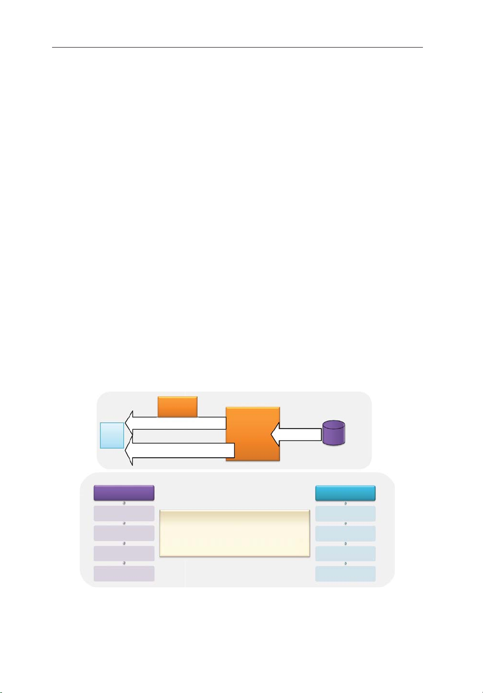
34 Design, Deployment and Performance of 4G-LTE Networks
The dedicated DRB does not necessarily require an extra IP address. The protocol stack uses
the trafc ow template (TFT) information to decide what to do with each IP packet. Uplink
and downlink trafc are mapped onto proper bearers based on TFT lters congured at the UE
and P-GW.
This concept makes the dedicated bearer activation similar to the secondary PDP context
activation in 3G that can be used by the IMS, for example, to ensure real-time data is delivered
promptly.
Due to the mapping between the radio bearer and lower layer logical channels, up to eight
DRBs can be set up to carry user plane data connected to multiple PDN. They are divided into
only one default EPS bearer and seven dedicated EPS bearers.
1.8.2 EPS Quality of Service (QoS)
In order to support a mixture of non-real-time and real-time applications, such as voice
and multimedia, the delay and jitter may become excessive if the ows of trafc are not
coordinated. Packet Switches should be able to classify, schedule, and forward trafc based
on the destination address, as well as the type of media being transported. This becomes
possible with QoS-aware systems.
The QoS for data radio bearers is provided to the eNB by the MME using the standardized
QoS attributes. Based on these congured attributes by the EPS, the protocol layers between
the UE and eNB can manage the ongoing scheduling of uplink and downlink trafc.
Various parameters are used to control and identify the QoS. The overall QoS parameters
are shown in Figure 1.30.
Uplink & Downlink
UE
eNode B
QCI, ARP, GBR/MBR
EPC
Dedicated QoS: QCI, GBR/MBR
Default QoS: QCI, APN-AMBR
EPS QoS Parameters
QCI
ARP
GBR
MBR
• QoS Class Identifier (QCI)
• Allocation/Retention Pr iority (ARP)
• Guaranteed bit Rate (GBR)
• Maximum Bit Rate (MBR)
• UE Aggregate MBR (UE-AMBR)
• Access Point Name Aggregate MBR (APN-MBR)
Figure 1.30 EPS QoS denitions and parameters.
Subscribed QoS:
• UE-AMBR per IMSI
• EPS QoS
Subscribed QoS
HSS
Non-GBR QoS GBR QoS
QCI
ARP
UE-AMBR
APN-MMBR
Uplink & Downlink
Page 65

LTE Network Architecture and Protocols 35
1.8.2.1 EPS Bearer QoS
EPS bearer QoS depends on the resource type; either guaranteed bit rate (GBR) or
non-guaranteed bit rate (non-GBR). The default DRB is always set up as a non-GBR. A
dedicated DRB can be either GBR or non-GBR [29].
As illustrated in Figure 1.30, the GBR-based EPS bearer consists of two distinct parameters;
GBR and MBR. The GBR indicates the bit rate that can be expected to be provided by a
GBR-based bearer, while the MBR limits the bit rate that can be expected to be provided by
this EPS bearer.
The GBR-based QoS parameters provide the eNB with information on the uplink and downlink rates for an E-RAB. E-RAB transports the packets of an EPS bearer between the UE
and the EPC based on these QoS parameters indicating the E-RAB’s maximum downlink bit
rate, maximum uplink bit rate, guaranteed downlink bit rate, and E-RAB’s guaranteed uplink
bit rate.
Non-guaranteed EPS bearers are subject to control through an AMBR (aggregate maximum
bit rate). The AMBR applies to both the subscriber and the APN associated with the subscriber,
and is dened as follows:
• UE-AMBR – value applies to the total bit rate that can be allocated to a subscriber for all its
non-GBR services. The UE-AMBR limits the aggregate bit rate across all non-GBR bearers
of a UE (excess trafc may get discarded by a rate-shaping function).
• APN-AMBR – value applies to the total bit rate that can be allocated to the subset of a
subscriber’s services associated with a particular APN. The APN-AMBR limits the aggregate bit rate across all non-GBR bearers and across all PDN connections of the same APN
(excess trafc may get discarded).
Similar to GBR-based QoS, the non-GBR parameters have uplink and downlink components.
1.8.2.2 ARP and QCI
The ARP (allocation and retention priority) controls the priority in bearer establishment, modication, or bearer release if resources are limited. In addition, it may be used to indicate which
bearers are dropped when there is congestion in the network. This parameter can be used for
GBR or non-GBR QoS.
The priority level of an ARP ranges from 0 to 15. The value 15 means “no priority,” whereas
the value 1 is the highest level of priority, with the value 0 being reserved. In addition, ARP
provides preemption capability on other E-RABs. This indicates whether the E-RAB will not
preempt other E-RABs or the E-RAB may preempt other E-RABs.
QCI (QoS class indicator) is another common QoS parameter in both GBR and non-GBR
EPS bearers. It provides a mapping from an integer value to specic QoS parameters that
controls how bearer level packets are forwarded.
QCI controls the packet forwarding, such as scheduling weights, admission thresholds,
queue management thresholds, and link layer protocol conguration. QCI values for an
E-RAB are typically pre-congured by the operator. QCI are categorized into nine different
indicators, as shown in Table 1.7 [29].
Page 66

36 Design, Deployment and Performance of 4G-LTE Networks
Table 1.7 Standardized QCI characteristics
QCI Resource Priority Packet delay budget Packet error loss Examples of
type (PDB) (ms) rate (PELR) services
1 GBR 2 100 10
2 4 150 10
3 3 50 10
4 5 300 10
−2
−3
−3
−6
Conversational voice
Conversational video (live
streaming)
Real-time gaming
Non-conversational video
(buffered streaming)
5 Non-GBR 1 100 10
6 6 300 10
−6
−6
IMS signaling
Video (buffered streaming,
TCP-based (www, e-mail,
ftp, p2p le sharing)
Voice, video, interactive gaming
Same as QCI 6 but used for
further differentiation
7 7 100 10
8 8 300 10
9 9 300 10
−3
−6
−6
Standardized QCI characteristics are not signaled on any interface. They are guidelines
for the pre-conguration of node-specic parameters for each QCI. They also ensure that
applications or services mapped to a given QCI receive the same minimum level of QoS in
multi-vendor network deployments and in the case of roaming. The typical QCI congured by
LTE’s operators with default EPS bearers carrying best effort trafc is 6 or 9.
An EPS bearer can include multiple SDFs. SDFs mapped to the same EPS bearer receive the
same bearer level packet forwarding treatment: scheduling policy, queue management policy,
rate-shaping policy, RLC conguration.
Every QCI (GBR and non-GBR) is associated with a priority level. Priority level 1 is the
highest priority level. Scheduling between different SDF aggregates should primarily be based
on the PDB (packet delay budget). For E-UTRAN, the priority level of a QCI may be used as
the basis for assigning the uplink priority per radio bearer.
The purpose of the PELR (packet error loss rate ) is to allow appropriate link layer protocol
congurations at RLC and HARQ in E-UTRAN. For a certain QCI the value of the PELR is
the same in uplink and downlink.
1.8.3 EPS Security Basics
In all 3GPP systems, security is needed to protect the user and control planes data. The security
procedures take place at different levels of the connection. In LTE, the EPS security functions
are [30]:
• Authentication and key agreement (AKA) – to prevent fraud that occurs when a third
party obtains a copy of a subscriber’s network identication information and uses it to fraudulently access the system.
• Ciphering – used to protect all user data and signaling from being overheard by an unau-
thorized entity.
Page 67

LTE Network Architecture and Protocols 37
• Integrity – protects signaling information from being corrupted. It is a message authenti-
cation function that prevents a signaling message from being intercepted and altered by an
unauthorized device.
1.8.3.1 Authentication
The MME initiates the AKA procedure by sending the authentication request message to the
UE, as shown in Figure 1.29. The MME sends the random challenge RAND and an authentication token, AUTN, for the network’s authentication [30].
Upon receipt of this message, the UE veries whether AUTN can be accepted. If AUTN is
acceptable, the UE’s USIM produces a RES and computes CK and IK (ciphering protection
key and integrity protection key).
Once the NAS security context is created, the UE (EMM) generates an authentication RES
message and includes RES in it. This NAS message is carried by the RRC signaling to the
eNB. The eNB forwards the message to the MME.
AKA involves interworking with the subscriber’s HSS in order to obtain AAA information to
authenticate the subscriber. During AKA, keys are created for AS and NAS integrity protection
and ciphering.
1.8.3.2 Integrity and Ciphering
The integrity and ciphering procedures involve both NAS and AS [30]:
• NAS security context activation – provides both integrity protection and ciphering for
NAS signaling. The procedure takes place between UE and MME.
• AS security context activation – provides integrity and ciphering protection for RRC
signaling in addition to ciphering for user plane data to be sent over the air interface. The
procedure takes place between UE and eNB.
Both authentication and NAS security context activation are not mandatory to occur in every
UE attach attempt. However, the AS security context is mandatory to take place for every connection the UE initiates with EPS. In 3GPP, integrity protection is mandated, but the ciphering
is only recommended. Figure 1.31 shows the signaling ow of these procedures.
Both UE and EPS negotiate the integrity and ciphering algorithms capabilities indicated
as part of “UE network capability” of the EMM attach request message. These algorithms
are [30]:
• EEA0 Null ciphering algorithm
• 128-EEA1 SNOW 3G-based ciphering algorithm
• 128-EEA2 AES (advanced encryption standard)-based ciphering algorithm
• EIA0 Null integrity algorithm
• 128-EIA1: SNOW 3G-based integrity algorithm
• 128-EIA2: AES-based integrity algorithm.
MME selects a NAS integrity algorithm and a NAS ciphering algorithm for the UE. The
MME is expected to select the NAS algorithms that have the highest priority according to the
ordered lists. The selected algorithm is indicated in the NAS security mode command message
Page 68

38 Design, Deployment and Performance of 4G-LTE Networks
MME/
GW
S-
Message is integrity protected
Message is ciphered and integrity protected
P-GW HSS
UL/DL Data
Internet
NAS EMM
carried on
SRB1
Access
Stratum
carried on
SRB1
UE
LTE-Uu S1 S5
RRC Connection Establishment
Signaling Radio Bearer
(SRB1) Activated
Attach Request + PDN Connectivity Request
AS Security Mode Command
AS Security Mode Complete
Attach Accept + EPS Default Bearer Setup
Attach Complete
Signaling Radio Bearer
(SRB2) & EPS Default
Bearer Activated
eNB
Authentication & Key Agreement
NAS Security Mode Command
NAS Security Mode Complete
All subsequent RRC messages are ciphered and integrity protected
Figure 1.31 NAS and AS security context activation.
to the UE and also includes the UE security capabilities in that message. This message is
integrity protected by MME with the selected algorithm.
The UE veries that the message from the MME contains the correct UE security capabili-
ties. This enables detection of attacks if an attacker has modied the UE security capabilities
in the initial NAS message.
The UE then generates NAS security keys based on the algorithms indicated in the NAS
security mode command and replies with an integrity protected NAS security mode complete
message. NAS security is activated at this point.
After this point, eNB creates the AS security context when it receives the keys from the
MME. The eNB generates the integrity and encryption keys and selects the highest priority
ciphering and integrity protection algorithms from its congured list that are also present in
the UE’s EPS security capabilities.
Upon reception of the AS security mode command, the UE generates integrity and encryp-
tion keys and sends an AS security mode complete message to the eNB.
1.8.4 EPS Idle and Active States
After the UE attaches to the EPS network, the data activity controls the states in which the UE
operates in the EPS network.
There are several states in each of the EPS entities, depending on the connection status. The
states are categorized in AS and NAS, as shown in Figure 1.32.
The user plane data can only ow when all the AS and NAS signaling connections and
bearers are in active/connected states.
On the air interface, the UE typically transitions into the RRC-idle state after successfully
attaching to the LTE system. UE remains in this state as long as there are no radio interface
Page 69

LTE Network Architecture and Protocols 39
Non-Access Stratum (NAS)
Detach, Attach, TAU Reject
EMM-
Registered
EMM-
Connected
ESM-Active
RRC-
Connected
EMM
ESM
RRC
EMM-
Deregistered
Attach Accept
RRC, S1 Connection Release
EMM-Idle
RRC, S1 Connection Est.
EPS Bearer Released
ESM-
Inactive
EPS Bearer Setup
Access Stratum (AS)
RRC Connection Release
RRC-Idle
RRC Connection Est.
Figure 1.32 EPS idle and active states for NAS and AS.
downlink or uplink packet activities with eNB. When a data activity is initiated by a user or
an application installed in the device, the UE immediately transits into RRC-connected state
and remains in this state until the packet connectivity timer, known as the “user inactivity”
timer, expires. The timer is congured in eNB and used to monitor the data activity for a user
within a timed window. When the timer expires, the eNB releases the RRC connection and
immediately triggers a UE’s state transition to the RRC-idle state.
The same concepts of NAS and AS states are also available in 3G systems. In the UMTS
air interface, the RRC states can be in either connected or idle mode. In connected mode,
the UE can be served in four different states: Cell_DCH (data channel), Cell_FACH (forward
access channel), Cell_PCH (paging channel), or URA_PCH. However, the state transitions in
the LTE air interface are simplied to only idle and connected mode, avoiding all the timers
and optimizations.
The RRC level state transition from connected to idle mode targets an improved battery
lifetime of the device. The battery consumption is expected to be more efcient in the idle
state when there is no connectivity or dedicated resource between the device and the eNB.
1.8.5 EPS Network Topology for Mobility Procedures
After the UE camps on an E-UTRAN cell, it uses the NAS procedure to register its presence
in a TA of the camped cell. This allows the EPC to page the user in the registered TA(s) while
UE is in idle mode.
Page 70

40 Design, Deployment and Performance of 4G-LTE Networks
MME Area 1
MME Area 2
TAI_A = {TAC_1, TAC2}
TAI_C = {TAC_4}
PCI = 24
TAI_B = {TAC_3}
Figure 1.33 EPS network topology for mobility procedure.
Normal
Some examples from
3GPP 24.301
EPS update type IE to
‘‘TA updating’’
PCI = 20
PCI = 44
PCI = 28
Update Trigger
PCI = 32
PCI = 36
Tracking Area
PCI = 58
Periodic
EPS update type IE to
‘‘periodic updating’’
when the UE
detects entering a
tracking area that
is not in the list of
tracking areas
that it previously
registered to in
the MME
when the UE
receives an
indication from the
lower layers that
the RRC
connection
released with
cause ‘‘load
balancing TAU
required’’
when the UE
receives an
indication of ‘‘RRC
Connection failure’’
from the lower
layers and has no
user uplink data
pending
Figure 1.34 Tracking area updating trigger conditions.
T3412 expiry
Example:
Timer value = 9
Unit = 2 (6 min)
= 9*6 = 54 min
Page 71

LTE Network Architecture and Protocols 41
Figure 1.33 shows an example of the different locations in which UE can register during the
mobility between different eNB cells.
A TA corresponds to the concept of the routing area (RA) used in UMTS. The TA consists
of a cluster of eNBs having the same tracking area code (TAC). The TAC provides a way to
track UE location in idle mode. TAC information is used by the MME when paging idle UE
to notify them of incoming data connections.
The MME sends the tracking area identity (TAI) list to the UE during the TA update procedure. TA updates occur periodically or when a UE enters a cell with a TAC not in the current
TAI list. The TAI list makes it possible to avoid frequent TA updates due to ping-pong effects
• PLMN ID (MCC + MNC)
• IMSI
• UE IP (for static IP allocation)
• P-GW ID (static P-GW allocation case)
• PDN ID (APN)
• IMSI
• PDN IP Address (Static IP)
• TAI List
• GUTI
• eNB S1-AP UE ID
• ECGI
• IMSI
• TAI
• GUTI
• S-TMSI
• IMSI
• IMEI
TAI 1
TAI 1
TAI 1
• C-RNTI
• TAI
Radio Bearer
DRB ID DL DRB ID UL S1 TEID UL
• Commissioning/Provisioning
• ID from P-GW
• MME S1-AP UE ID
• eNB ID
• ECGI
• MMEI
• TAI
• ECGI
• PDN IP Address (Dynamic IP)
S1 Bearer S5 Bearer
E-RAB
TAI 2
EPS Bearer
• ID from UE • ID from eNB • ID from MME • ID from HSS
• ID from S-GW
HSS
• IMSI
• IMSI
• P-GW ID
• MMEI
• PDN ID (APN)
• GUMMEI
• TAI List allocation Policy/Rule
• IMSI
MME
• IMSI
• P-GW ID
• PDN ID (APN)
S-GW
S1 TEID UL S5 TEID UL S5 TEID UL
E-RAB ID
• GUTI
• IMSI
• P-GW ID
• PDN ID (APN)
• ECGI
• ECGI
IMSI TAI GUTI
PLMN ID PLMN ID PLMN ID MMEI
MCC
3 digits
MNC
2~3 digits
IMSI
MSIN
9~10 digits
MCC
12 bits
MNC
8~12 bits
TAC
16 bits
TAI
MCC
12 bits
MNC
8~12 bits
MMEGI
16 bits
GUMMEI
SPR
PCRF
• IMSI
• PDN ID (APN)
• UE IP
• P-GW ID
• IP Pool (for dynamic IP
allocation)
P-GW
EPS Bearer ID
MMEC
8 bits
GUTI
UE IP
S-TMSI
40 bits
MME
APN
M-TMSI
32 bits
PDN
Figure 1.35 EPS identiers. (Source: [31]. Reproduced with permission of NMC group.)
Page 72

42 Design, Deployment and Performance of 4G-LTE Networks
Table 1.8 EPS identier denitions
Identier Description Assignment Denition
IMSI International mobile
subscriber identity
PLMN ID Public land mobile
network identier
Unique identication of mobile
(LTE) subscriber
Network (MME) gets the
PLMN of the subscriber
IMSI (not more than
15 digits) = PLMN
ID + MSIN = MCC +
MNC + MSIN
Unique identication of PLMN PLMN ID (not more
than 6 digits) =
MCC + MNC
MCC Mobile country code Assigned by regulator 3 digits
MNC Mobile network code Assigned by regulator 2– 3 digits
MSIN Mobile subscriber
Assigned by operator 9–10 digits
identication
number
GUTI Globally unique
temporary UE
identity
TIN Temporary identity
used in next update
Identify a UE between the UE
and the MME on behalf of
IMSI for security reasons
GUTI is stored in TIN
parameter of UE’s MM
GUTI (not more than
80 bits) = GUMMEI +
M-TMSI
TIN = GUTI
context. TIN indicates which
temporary ID to use in the
next update
S-TMSI SAE temporary
mobile subscriber
identity
M-TMSI MME mobile
Locally identify a UE in short
within a MME group (unique
within an MME pool)
Unique within an MME 32 bits
S-TMSI (40 bits) =
MMEC + M-TMSI
subscriber identity
GUMMEI Globally unique
MME identity
MMEI MME identier Identify an MME uniquely
Identify an MME uniquely in
global
GUTI contains GUMMEI
within a PLMN
GUMMEI (not more
than 48 bits) = PLMN
ID + MMEI
MMEI (24 bits) =
MMEGI + MMEC
Operator commissions at eNB
MMEGI MME group identier Unique within PLMN 16 bits
MMEC MME Code Identify an MME uniquely
8 bits
within an MME group
S-TMSI contains MMEC
C-RNTI Cell-radio network
temporary identier
eNB S1AP
UE ID
MME S1AP
UE ID
eNB S1 application
protocol UE ID
MME S1 application
protocol UE ID
IMEI International mobile
equipment identity
IMEI/SV IMEI/software
version
ECGI E-UTRAN cell global
identier
Identify a UE uniquely in a cell 0 x 0001 ∼ 0 x FFF3
(16 bits)
Uniquely identify UE on S1-
32-bit integer
MME interface in eNB
Uniquely identify UE on S1-
32-bit integer
MME interface in MME
Identify a ME (mobile
equipment) uniquely
Identify a mobile equipment
uniquely
IMEI (15 digits) =
TAC + SNR + CD
IMEI/SV (16 digits) =
TAC + SNR SVN
Identify a cell globally ECGI (not more than
EPC can know UE location
based on ECGI
52 bits) = PLMN
ID+ ECI
Page 73

LTE Network Architecture and Protocols 43
Table 1.8 (continued)
Identier Description Assignment Denition
ECI E-UTRAN cell
identier
Global
eNB ID
eNB ID eNodeB identier Identify an eNB within a PLMN 20 bits
P-GW ID PDN GW identier Identify a specic PDN-GW IP address (4 bytes) or
TAI Tracking area identity Identify tracking area TAI (not more than
TAC Tracking area code Indicate eNB to which tracking
TAI List Tracking area identity
PDN ID Packet data network
EPS BearerIDEvolved packet
E-RAB ID E-UTRAN radio
DRB ID Data radio bearer
LBI Linked EPS
TEID Tunnel end point
Global eNodeB
identier
list
identity
system bearer
identier
access bearer
identier
identier
bearer ID
identier
Identify a cell within a PLMN ECI (28 bits) = eNB
ID + Cell ID
Identify an eNB globally in the
network
HSS assigns P-GW for PDN
connection of each UE
Globally unique
area the eNB belongs (per
Cell)
Unique within a PLMN
UE can move into the cells
included in TAL list without
location update (TA update)
Globally unique
Identify a PDN (IP network), a
mobile data user wants to
communicate with
PDN identity (APN) used to
determine P-GW and point of
interconnection with a PDN
With APN as query parameter
to the DNS procedures, the
MME will receive a list of
candidate P-GWs, and then a
P-GW is selected by MME
with policy
Identify EPS bearer (default or
dedicated) per UE
Identify an E-RAB per an UE 4 bits
Identify a DRB per an UE 4 bits
Identify the default bearer
associated with a dedicated
EPS bearer
Identify the end point of a GTP
tunnel when the tunnel is
established
Global eNB ID (not
more than 44 bits) =
PLMN ID + eNB ID
FQDN (variable
length)
32 bits) = PLMN
ID + TAC
16 bits
Variable length
PDN Identify = APN =
APN.NI + APN.OI
(variable length)
4 bits
4 bits
32 bits
(Source: [31]. Reproduced with permission of NMC group.)
Page 74

44 Design, Deployment and Performance of 4G-LTE Networks
along TA borders. This is achieved by including the old TAC in the new TAI list received at
TA update. When the MME pages a UE, a paging message is sent to all cells in the TAI list.
In the example shown in Figure 1.33, if the UE performs EPS registration from TAI_A,
the MMEs send TAC_1, and TAC_2 in the TAI List, implying that the UE can roam around
in the eNBs with the TACs belonging to this TAI list without having to re-register with the
EPS network. This procedure saves on the signaling load. The UE re-registers with a TAU
procedure if the UE enters into the coverage areas of eNB that are part of TAC_3 (in TAI_B)
and TAC_4 (i n TAI_C).
The TA dimensioning and planning in the network are performed in the optimization stage.
The TA planning can prevent the ping-pong effect of TAU to achieve optimization between
paging load, registration overhead, UE battery, and improved paging success rate. In the same
example, the paging area for UE served in TAI_A will be for all cells belonging to TAC_1 and
TAC_2, but the registration area will be limited to TAI_A only.
TA updating can be either periodical or based on the mobility conditions of the device.
Figure 1.34 summarizes the triggering conditions of the TAU procedure [28].
The MME area is the part of the network served by an MME. The MME area consists of one
or more tracking areas. All cells served by an eNB are included in an MME area. There is no
one-to-one relationship between an MME area and an MSC/VLR area. Multiple MMEs may
have the same MME area (pool area) and MME areas may overlap each other.
1.8.6 EPS Identiers
The LTE system is designed to simplify the procedures carried on EPS. This is possible by
designing and assigning the required identiers at different interfaces within the EPS system.
The different identities dened in the EPS system are shown in Figure 1.35 and each is
dened in Table 1.8 [31]. Different types of identiers are needed between the eNB and the UE
as part of the RNTI (radio network temporary identier). These RNTIs are used for different
procedures such as paging, random access, and system information on the air interface. They
are not shown in the gure, but are discussed in detail in the next chapter.
References
[1] 3GPP (2008) All-IP Network (AIPN) Feasibility Study. TR 22.978.
[2] 3GPP (2008) 3rd Generation Partnership Project; Technical Specication Group Services and
System Aspects; 3GPP System Architecture Evolution: Report on Technical Options and
Conclusions. TR 23.882 V8.0.0.
[3] 3GPP (2008) Study on Evolved UTRA and UTRAN. TR 25.912.
[4] 3GPP (2008) Requirements for Evolved UTRA (E-UTRA) and Evolved UTRAN (E-UTRAN).
TR 25.913.
[5] 3GPP (2010) 3rd Generation Partnership Project; Technical Specication Group Radio Access
Network; Evolved Universal Terrestrial Radio Access Network (E-UTRAN); S1 Application
Protocol (S1AP). TS 36.413 V8.10.0.
[6] 3GPP (2011) 3rd Generation Partnership Project; Technical Specication Group Core Network
and Terminals; 3GPP Evolved Packet System (EPS); Evolved General Packet Radio Service
(GPRS) Tunnelling Protocol for Control Plane (GTPv2-C). TS 29.274 V8.11.0.
Page 75

LTE Network Architecture and Protocols 45
[7] 3GPP (2010) 3rd Generation Partnership Project; Technical Specication Group Core Network
and Terminals; Proxy Mobile IPv6 (PMIPv6) based Mobility and Tunnelling Protocols. TS
29.275 V8.8.0.
[8] 3GPP (2010) 3rd Generation Partnership Project; Technical Specication Group Radio Access
Network; Evolved Universal Terrestrial Radio Access Network (E-UTRAN); Architecture
Description. TS 36.401 V8.8.0.
[9] 3GPP (2008) 3rd Generation Partnership Project; Technical Specication Group Radio Access
Network; Evolved Universal Terrestrial Radio Access Network (E-UTRAN); X2 General
Aspects and Principles. TS 36.420 V8.1.0.
[10] 3GPP (2012) 3rd Generation Partnership Project; Technical Specication Group Radio Access
Network; Evolved Universal Terrestrial Radio Access (E-UTRA); User Equipment (UE) Radio
Access Capabilities. TS 36.306 V10.7.0.
[11] IETF (2007) Stream Control Transmission Protocol. RFC 4960.
[12] IETF (1980) User Datagram Protocol. RFC 768.
[13] IETF (2003) Diameter Base Protocol. RFC 3588.
[14] 3GPP (2009) Evolved Universal Terrestrial Radio Access (E-UTRA) and Evolved Universal
Terrestrial Radio Access Network (E-UTRAN); Overall Description. TS 36.300 V8.5.0.
[15] 3GPP (2010) General Packet Radio System (GPRS) Tunnelling Protocol User Plane (GTPv1-U).
TS 29.281V9.3.0.
[16] 3GPP (2010) General Packet Radio Service (GPRS); Service Description. TS 23.060 V9.6.0.
[17] 3GPP (2012) Evolved Packet System (EPS); Mobility Management Entity (MME) and Serving
GPRS Support Node (SGSN) Related Interfaces Based on Diameter Protocol. TS 29.272 V9.9.0.
[18] 3GPP (2011) Evolved Packet System (EPS); 3GPP EPS AAA Interfaces. TS 29.273 V9.7.0.
[19] 3GPP (2010) Mobility Management Entity (MME) – Visitor Location Register (VLR) SGs Inter-
face Specication. TS 29.118 V9.3.0.
[20] 3GPP (2011) Policy and Charging Control Over Gx Reference Point. TS 29.212 V9.6.0.
[21] 3GPP (2010) Charging Management; Charging Architecture and Principles. TS 32.240 V9.1.0.
[22] 3GPP (2011) Interworking between the Public Land Mobile Network (PLMN) supporting Packet
Based Services and Packet Data Networks (PDN). TS 29.061 V10.4.0.
[23] 3GPP (2011) Cell Broadcast Centre interfaces with the Evolved Packet Core. TS 29. 168 V
10.0.0.
[24] Deering, S. and Hinden, R., IETF (1998) Internet Protocol, Version 6 (IPv6) Specication. RFC
2460.
[25] IETF (1981) Internet Protocol (STD 5). RFC 791.
[26] 3GPP (2009) Technical Realization of Cell Broadcast Service (CBS). TS 23.041 V8.2.0.
[27] 3GPP (2010) Sv interface (MME to MSC, and SGSN to MSC) for SRVCC. TS 29.280 V9.2.0.
[28] 3GPP (2011) 3rd Generation Partnership Project; Technical Specication Group Core Network
and Terminals; Non-Access-Stratum (NAS) Protocol for Evolved Packet System (EPS). TS
24.301 V8.10.0.
[29] 3GPP (2012) 3rd Generation Partnership Project; Technical Specication Group Services and
System Aspects; Policy and Charging Control Architecture. TS 23.203 V10.8.0.
[30] 3GPP (2011) 3rd Generation Partnership Project; Technical Specication Group Services
and System Aspects; 3GPP System Architecture Evolution (SAE); Security Architecture. TS
33.401 V8.8.0.
[31] NMC http://www.nmcgroups.com/les/download/NMC.LTE%20Identiers.v1.0.pdf (accessed
23 September 2013).
Page 76

Page 77

2
LTE Air Interface and Procedures
Mohamed A. El-saidny
2.1 LTE Protocol Stack
The LTE (long term evolution) air interface provides connectivity between the user equipment
(UE) and the eNB (eNodeB). It is split into a control plane and a user plane, as described in
Chapter 1. Among the two control plane signalings, the rst is provided by the access stratum (AS) and carries signaling between the UE and the eNB. The second carries non-access
stratum (NAS) signaling messages between the UE and the MME (mobility management
entity), which is piggybacked into an RRC (radio resource control) message. The user plane
delivers the IP (Internet protocol) packets to and from the EPC (evolved packet core), the
S-GW (serving gateway), and the PDN-GW (packet data network gateway).
The structure of the lower layer protocols for the control and user planes in AS are the same.
Both planes utilize the protocols of PDCP (packet data convergence protocol), RLC (radio
link control), and MAC (medium access control), as well as the PHY (physical layer) for the
transmission of the signaling and data packets [1].
NAS is the layer above the AS layers. There are also two planes in NAS; the higher layer
signaling related to the control plane and the IP data packets of the user plane. NAS signaling exists in two protocol layers, EMM (EPS mobility management) and ESM (EPS session
management), as discussed in Chapter 1. The NAS user plane is IP-based. The IP data packets
pass directly into the PDCP layer for processing and transmission to or from the user.
Figure 2.1 illustrates the radio interface protocol stack. The protocol stacks reside in both
the UE and the E-UTRAN (evolved universal terrestrial radio access network). Control and
user plane data ow on the entire stack based on the type of trafc being exchanged from or to
the UE. It is illustrated in the gure that the NAS signaling uses the services of RRC, which
is then mapped into the PDCP. On the user plane, IP packets are also mapped into the PDCP
layer and then delivered down to the lower layers for transmission.
This chapter describes the air interface of LTE, focusing on the AS protocol layers. It then
provides an overview of the PHY layer structure and how it utilizes OFDMA (orthogonal frequency division multiple access) for transmission. The chapter concludes with an end-to-end
Design, Deployment and Performance of 4G-LTE Networks: A Practical Approach, First Edition. Ayman Elnashar,
Mohamed A. El-saidny and Mahmoud R. Sherif.
© 2014 John Wiley & Sons, Ltd. Published 2014 by John Wiley & Sons, Ltd.
Page 78

48 Design, Deployment and Performance of 4G-LTE Networks
EMM & ESM
SRB DRB Setup
Radio Bearer
Logical Channels
Transport Channels
Application Layer
RRC
PDCP
Ciphering
& RoHC
RLC
MAC
PHY
Integrity &
Ciphering
TCP/IP Stack
NON Access
Stratum
NAS Layer
Access
Stratum
Layer 3
Access
Stratum
Layer 2
SDU
PDU
Access
Stratum
Layer 1
Physical Channels
LTE-Uu
EPS Bearer
RRC
SRB DRB Setup
PDCP
RLC
MAC
PHY
Application Data
S1
TCP/IP Stack
EMM &
ESM
MME/ S-GW/
P-GW
Application Layer
TCP/IP Stack
Signaling Packets
(Control Plane)
Data Packets
(User Plane)
SGi
Internet &
CNs
Figure 2.1 LTE protocol stacks.
procedure as when the UE powers-up in an LTE network, interchanging data with the network
and mobiles around the eNBs. A comparison with the HSPA(+) PHY layer and procedures is
also provided to clarify the concepts of the LTE channels.
2.2 SDU and PDU
Each layer within the protocol stack uses the services of the layer below it and offers services
to the layer above it. For example, RRC uses the services of RLC and offers services to the
NAS layer. Additionally, each layer in the UE communicates with its peer layer in E-UTRAN,
as shown in Figure 2.1.
The user plane IP packets are typically sizable (in bytes, for example, one IP packet is
1500 bytes). The control plane signaling can also contain a larger size message than the air
interface can handle in certain radio conditions. Therefore, the packets are not exactly transmitted to the lower layers as received from the upper layers. The packets are usually segmented
into smaller units for over-the-air transmission, to maintain the bandwidth of the air interface
as well as the radio conditions of the UE.
The unit of data exchanged between entities’ peer layers is called a protocol data unit
(PDU). For example, the RRC layers of the UE and E-UTRAN communicate with each
other via signaling messages that are encapsulated in a PDU. Figure 2.2 demonstrates the
denitions of PDU.
To send an uplink PDU from the UE’s RRC to the E-UTRAN’s RRC layer, it passes down
the UE’s protocol stack to PDCP, RLC, MAC, and PHY, and then up into the E-UTRAN’s
Page 79

LTE Air Interface and Procedures 49
UE E-UTRAN
NAS NAS
NAS-PDU =
RRC-SDU
RRC
RRC-PDU =
PDCP-SDU
PDCP
PDCP-PDU
= RLC-SDU
RLC RLC
NAS
PDU
RRC
PDU
PDCP
PDU
RLC
PDU
SDU
RRC
SDU
PDCP
SDU
RLC-PDU =
MAC-SDU
MAC MAC
MAC
PDU
SDU
Figure 2.2 Protocol layer SDUs and PDUs.
protocol stack to the RRC layer. On the other hand, the data sent up or down the protocol stack
in one of these entities is called a service data unit (SDU), as indicated in Figure 2.2.
For example, the UE’s RRC layer sends an RRC signaling message to the PDCP as an SDU.
The PDCP transforms this SDU to the RLC layer down the stack. The RLC layer converts them
into one or more RLC PDUs after performing functions such as segmentation, concatenation,
and RLC headers addition. These RLC PDUs are then constructed as MAC SDUs. The MAC
SDU consists of multiple MAC PDUs coming from each part of the stack, for example, when
there are user data to be sent in parallel with signaling. The MAC PDUs are then mapped to
the transport block (TB) to be sent on the PHY layer and then over the air to the serving cell
of the eNB.
Page 80

50 Design, Deployment and Performance of 4G-LTE Networks
In the receiving direction, the eNB decodes the TB which contains the MAC PDUs. After
a reordering mechanism is performed, the PDUs are assembled back into RLC SDUs after
removing the headers. Then, RLC delivers the SDUs to the PDCP and then to the RRC layer.
At the RLC layer in this example, one SDU will contain multiple RLC PDUs, and the delivery
to the PDCP and then to the RRC will only occur after receiving all the RLC PDUs that
construct the nal RRC SDU. This SDU now contains the original RRC signaling message
sent by the UE.
2.3 LTE Radio Resource Control (RRC)
The RRC constitutes the main air interface protocol for the control plane signaling messages
[1]. In general, signaling messages are needed to regulate the UE behavior in order to comply
with the network procedures. Each signaling message the EPS (evolved packet system), sends
to the UE, or vice versa, is comprised of a set of system parameters. For example, the eNB
needs to communicate the parameters related to mobility procedures when the UE needs to
hand over from one cell to another. These parameters will be sent to the UE in a specic RRC
message.
In order for the messages to be transferred between the UE and the eNB, the RRC layer
uses the services of the PDCP, RLC, MAC, and PHY. During the course of this mapping, the
packets are directed on a radio bearer, referred to as the signaling radio bearer, SRB.
The RRC handles all the signaling between the UE and the E-UTRAN. Additionally, the
core network NAS signaling is also carried by a dedicated RRC message. When carrying NAS
signaling, the RRC does not alter the information but instead provides the delivery mechanism.
As described in Chapter 1, a UE in the LTE network can camp on different states. For a
UE with active connection with the EPS, its RRC state will be RR-connected. The types of
signaling messages and parameters exchanged in this state handle the UE for mobility, that is,
handover, and all the associated radio bearer congurations for the data transmission. For a UE
with inactive connection, its RRC state will be RRC-idle. In this case, the UE would not have
a dedicated radio bearer (DRB) for data transmission. As a result, the only signaling needed
in this state would target paging the UE for incoming calls, or parameters related to mobility
in the idle state, that is, cell reselection.
Table 2.1 describes the key LTE RRC signaling messages and their corresponding UMTS
ones that closely match the purpose of such messages. The table does not show the NAS-related
message names.
The eNB typically uses two methods for conrming that the message has reached the UE.
One method is when the UE sends a complete RRC message in response to the RRC message from eNB. The eNB treats this “complete message” as an RRC acknowledgment. For
example, when the eNB sends “RRC connection reconguration,” it waits to receive the UE’s
“RRC connection reconguration complete” in order to complete the RRC procedure. There
are RRC timers controlling the timeout duration before the eNB decides to tear down the RRC
connection. If the connection is disconnected due to an incomplete RRC procedure, the call
is also considered as a dropped call. Hence, dropped calls due to incomplete RRC signaling
procedure is an area of optimization in the LTE network, likewise UMTS.
Another RRC conrmation method is a lower layer acknowledgment at RLC and PHY (a
joint operation with MAC). This method is required to ensure that any missing segments of
Page 81

LTE Air Interface and Procedures 51
Table 2.1 RRC signaling messages
LTE RRC
message
name
System/master
information
blocks (SIBs
and MIB)
RRC
state/direction
Similar UMTS
RRC message
name
Idle/from eNB System/master
information blocks
Main purpose of message
Carries parameters for
• UE to identify the network
(PLMN) and cell (tracking
area)
• idle mode mobility
procedures for cell
reselection
• RACH procedures
• paging procedures
Paging Idle/from eNB Paging type 1 Paging the UE from idle mode
Paging type 2 used
for any service
for paging in
connected mode
RRC connection
request
Connecting/fromUERRC connection
request
UE identity
Call establishment cause
RRC connection
setup
Connecting/from
eNB
RRC connection
set-up
Carries parameters for:
• SRB1 mapping to all lower
layers
• RLC parameters for SRB1
• initial physical layer
parameters
RRC connection
set-up complete
UE capability
information
Security mode
command
RRC connection
reconguration
Connected/fromUENAS message, that is,
initial direct
transfer
Connected/fromUERRC connection
set-up complete
Connected/from
eNB
Connected/from
eNB
Security mode
command
Measurement control
message
• MME ID
• Piggybacked EMM NAS
signaling message
UE capabilities: RAT supported,
bands, LTE capabilities
Ciphering and integrity
Carries connected mode
mobility parameters
(handover) and neighbor cell
information
Measurement
report
Connected/fromUEMeasurement report Carries the measurements by
the UE for the serving and
neighbor cells, depending on
the parameters in “RRC
connection reconguration”
RRC connection
reconguration
Connected/from
eNB
Radio bearer set-up,
radio bearer
reconguration,
physical channel
reconguration
Carries parameters needed for:
• establishing DRB and
mapping to lower layers
• SRB2 mapping for lower
layers
(continued overleaf )
Page 82

52 Design, Deployment and Performance of 4G-LTE Networks
Table 2.1 (continued)
LTE RRC
message
name
RRC connection
release
RRC
state/direction
Connected/from
eNB
Similar UMTS
RRC message
name
RRC connection
release
Main purpose of message
• any lower layer parameter
reconguration
• physical layer parameters and
recongurations
• Release the RRC connection.
It transitions the UE from
RRC-connected to RRC-idle
• It can also redirect the UE to
select another RAT after the
release (i.e., LTE to UMTS
redirection)
the RRC message on the air interface, in deteriorating RF conditions, is being retransmitted in
a timely manner before being delivered to the RRC layer.
Not all RRC messages require an RRC complete message from the UE; it depends on
the procedure being carried out. However, all RRC-connected mode messages require
lower layer acknowledgments. The RRC complete messages are also delivered from the
lower layers, and hence only require lower layer acknowledgments. For any dropped call due
to signaling message timeout, both the RRC layer and all lower layers are potential areas
of investigation.
2.4 LTE Packet Data Convergence Protocol Layer (PDCP)
The PDCP layer is responsible for the following key functions [2]:
1. It transfers the control and user plane data to and from the upper layers. It receives SDUs
from the upper layers and sends PDUs to the lower layers. In the other direction, it receives
PDUs from the lower layers and sends SDUs to the upper layers.
2. It is responsible for security functions. It applies ciphering for user and control plane bear-
ers, if congured. It may also perform integrity protection for control plane signaling messages, both RRC and NAS.
3. It performs header compression services to improve the efciency and performance of
over the air transmissions. The header compression is based on robust header compression
(ROHC).
4. It is responsible for in-order delivery of packets and duplicate detection services to
upper layers between the source and target eNB during the handover procedure in the
RRC-connected state.
Page 83

LTE Air Interface and Procedures 53
2.4.1 PDCP Architecture
For a UE in the RRC-connected state, the PDCP acts as the rst AS layer to exchange the
control and user planes packets. Figure 2.3 illustrates the functions of the PDCP layer.
2.4.2 PDCP Data and Control SDUs
While being constructed from the upper layer SDUs, a PDU holds the data eld, the SDU
being sent from upper layers, in addition to other needed header information.
The PDCP’s PDU header includes a 5-bit sequence number (SN) space for the control plane.
For the user plane PDCP PDUs, 12 and 7-bit SN are supported and congured on a per DRB
basis. For example, the 12-bit SN format applies only to RLC acknowledged mode (AM)
operation of DRB. Additionally, a header eld referred to as “D/C” indicates whether the
PDU carries user plane data or control information generated at the PDCP layer. The D/C eld
enables the receiving entity to direct the received PDCP PDU to the intended radio bearer.
The control plane packets are integrity protected, as shown in Figure 2.3. Therefore, a
32-bit MAC-I (message authentication code for integrity) is attached to the PDCP’s PDUs.
Control Plane
(NAS or RRC) on
SRB1/SRB2
PDCP SDU PDCP SDU
Sequence
Numbering
Integrity
Protection
Ciphering Ciphering
Add PDCP
Header
Transmitting Entity (UE or eNB) Receiving Entity (UE or eNB)
Lower Layers
PDUs constructed
User Plane on
DRB
Sequence
Numbering
Header
Compression
(RoHC)
Add PDCP
Header
Radio Interface
Control Plane
(NAS or RRC) on
SRB1/SRB2
PDCP SDU PDCP SDU
Integrity
Verification
Deciphering Deciphering
Remove PDCP
Header
Lower Layers PDUs re-
assembled
Figure 2.3 PDCP layer, functional view.
User Plane on
DRB
In-order delivery
and duplicate
detection
Header
Decompression
(RoHC)
Remove PDCP
Header
Page 84

54 Design, Deployment and Performance of 4G-LTE Networks
The MAC-I is calculated using the transmitted message, an integrity protection key for the
user, and other time varying parameters depending on the EPS integrity algorithm (EAI)
congured by the RRC layer. Chapter 1 describes the integrity protection architecture, and
more information is provided in 3GPP (third generation partnership project) [3]. The PDCP
attaches the MAC-I to the end of the control plane PDU. The integrity protection stage does
not apply to user plane data being transmitted through the PDCP layer.
2.4.3 PDCP Header Compression
At this point, from the ow shown in Figure 2.3, PDCP PDU has been constructed for the
user plane data packet with the proper PDCP headers, that is, SN. PDCP receives IP packets
for transmission from the application layer. On top of IP, the transport protocol may be TCP
(transmission control protocol), UDP (user datagram protocol), or RTP (real-time transport
protocol) generating additional large headers. The header overhead may be reduced by using
compression techniques such as RoHC supported in LTE, based on [4]. Header compression
also reduces transmission delay and packet loss rate. By this denition, this stage does not
apply to the PDUs of the control plane at PDCP.
There is one instance of RoHC for each PDCP entity. That means there is one RoHC instance
for each radio bearer when multiple DRBs are congured. The header compression entity is
implemented at the transmitter, and the decompression entity is implemented at the receiver.
2.4.4 PDCP Ciphering
The data is ciphered by the PDCP protocol between the UE and the eNB. Both control and
user planes can be ciphered. For the control plane, only RRC signaling is ciphered by PDCP.
The NAS signaling is ciphered separately at the NAS layers, as discussed in the procedure in
Chapter 1.
LTE provides the ability to select from several ciphering algorithms, such as SNOW 3G
and the advanced encryption standard (AES) algorithm [3]. The input parameters to the
128-bit EEA (EPS encryption algorithm) for ciphering and deciphering are congured by
the RRC layer.
2.4.5 PDCP In-Order Delivery
At the receiver side, once the PDCP receives the PDUs from the transmitter entity, the PDCP
header is removed from the PDCP PDUs. The user plane data de-ciphering and header
de-compression is then preformed. For the control plane, data de-ciphering and integrity
protection is veried, after which the PDCP SDUs are delivered to the upper layers.
In-order delivery check and duplicate detection is performed before delivering the user plane
PDCP SDUs to the higher layers [2]. Typically, lower layers deliver PDCP PDUs in-order to
the receiver side. However, in some cases such as handover from an eNB to another or when
the call is being re-established after a drop in degrading RF conditions, the PDCP PDUs may
experience holes in the SN when the lower layers resets.
SN will be tracked in the PDCP layer from the headers attached to the PDCP PDUs being
received. In the case of detecting SN holes, PDCP will request a PDCP status report from
Page 85

LTE Air Interface and Procedures 55
Table 2.2 LTE and HSPA PDCP function comparison
Criteria PDCP in LTE PDCP in HSPA
PDCP entity In eNB In RNC
PDCP used for control plane signaling Yes No
PDCP used for user plane data Yes Yes
PDCP performs ciphering and integrity protection Yes No
RoHC header compression support Yes Yes
In sequence delivery and duplicate detection support Yes No
the transmitter, indicating a retransmission request of the lost PDCP PDU. If the packets are
received out of order within the reordering window, the PDCP performs reordering before
delivering the packets to the upper layers. The reordering window size is 2048. If any sequential
PDU does not arrive within this window, the PDCP layer sends the remaining PDUs in-order
to the upper layer.
Due to this nature of delivery, PDCP provides discard timer functionality and the ability to
retransmit missing PDCP PDUs. The transmitter entity will maintain a buffer to store transmitted PDUs to support this functionality. The timer is congured by the RRC layer. The SDU
is nally discarded when the timer expires.
2.4.6 PDCP in LTE versus HSPA
LTE implements PDCP in both the user plane and the control plane. This is different than
UMTS, where the PDCP layer is only designed for the user plane. The main reason for this
difference is that the PDCP in LTE takes on the role of security, encryption and integrity.
This is one of the main differences of LTE’s PDCP layer. For HSPA (high speed packet
access), ciphering is performed in the RLC layer and integrity protection is performed in the
RRC layer.
Both LTE and HSPA support PDCP header compression, although HSPA supports multiple compression techniques such as IP Header Compression as well as RoHC for the user
plane data.
The main reason for PDCP being implemented in eNB in LTE is that the header compression parameters are reset during handover. In HSPA, the header compression parameters are
transferred across RNCs (radio network controllers), if lossless SRNC (serving radio network
controller) relocation is required. This is the reason for PDCP being implemented in the RNC
for the HSPA system. The major differences are summarized in Table 2.2.
2.5 LTE Radio Link Control (RLC)
The RLC is part of the protocol layers in both the UE and the eNB. In the downlink, it uses the
services of PDCP and offers services to the MAC layer. In the uplink, it uses the services of the
MAC layer and offers services to the PDCP layer. In some cases, the RLC uses the services of
the RRC directly. This occurs during the establishment of RRC connection prior to SRB1 or
SRB2 set-up. In this case, the RRC message will be sent on SRB0, a common control channel
Page 86

56 Design, Deployment and Performance of 4G-LTE Networks
Upper Layers (RRC or PDCP SDUs)
Transmitting
TM RLC Entity
PDUs PDUs PDU
PDUs PDUs PDUs PDUs
Receiving
TM RLC Entity
Receiving
TM RLC Entity
Transmitting
TM RLC Entity
Transmitting
UM RLC Entity
Lower Layers (MAC and PHY)
Lower Layers (MAC and PHY)
Receiving
UM RLC Entity
Upper Layers (RRC or PDCP SDUs)
Receiving
UM RLC Entity
PDUs PDUs PDUs
Transmitting
UM RLC Entity
AM RLC Entity
PDUs PDUs
AM RLC Entity
Figure 2.4 Overview model of the RLC sublayer.
(CCCH) discussed later in this chapter, right at the time the UE is connecting; that is, moving
from RRC-idle to RRC-connected.
As all other protocol layers, the RLC functions support both control and user plane packets,
including [5]:
1. Transfer of upper layer PDUs.
2. Error correction through ARQ (automatic repeat request).
3. Concatenation, segmentation, and re-assembly of SDUs.
4. Resegmentation of RLC PDUs.
5. In-sequence delivery and duplicate detection of RLC PDUs.
6. Protocol error detection and recovery mechanism.
7. RLC SDU discarding mechanism.
eNode B
UE
2.5.1 RLC Architecture
The RLC layer receives packets from the upper layer radio bearers, signaling, or data, as SDUs.
The transmission entity in the RLC layer converts them into RLC PDUs after performing the
key functions: segmentation, concatenation, and adding RLC headers, depending on the RLC
mode. In the other direction, the receiving entity decodes the RLC PDUs from the MAC layer.
After performing reordering, the PDUs are assembled back into RLC SDUs and delivered to
the upper layer. Figure 2.4 illustrates the model of the RLC layer [5].
The RLC PDUs are of variable sizes and can be formatted based on the TB available in MAC
from the underlying PHY channel. MAC noties the RLC when a transmission opportunity
becomes available, including the total number of RLC PDUs that can be transmitted in the
current transmission opportunity.
Page 87

LTE Air Interface and Procedures 57
2.5.2 RLC Modes
RLC is a pivotal layer in the PDU transmission across the protocol stack, and is therefore called
the “radio link” control. One of the main functions of the RLC is to provide ARQ operation
of the RLC PDUs between the UE and the eNB.
ARQ is a procedure that controls the retransmission of the missing PDUs. The PDU retransmission in the protocol stack is mainly handled by MAC, jointly with the PHY and RLC layers.
In MAC, the retransmission is handled by H-ARQ (hybrid automatic repeat request) discussed
in Section 2.6. Packet retransmissions at both of these layers protect the control and user plane
data for a reliable and quality connection.
There are different layers and services that go through the RLC including SRB and DRB
data packets, the retransmission mechanism is not necessarily required for all types of these
packets. Therefore, RLC PDUs can operate in three different modes: transparent mode (TM),
unacknowledged mode (UM), or Acknowledged Mode (AM).
The mode of operation controls the applicability and functionality of the RLC. TM is only
applicable for control plane signaling related RLC packets. AM or UM can be used for control
or user plane RLC packets. The chosen mode is controlled by the RRC and conveyed to the
UE in the RRC messages at the time of establishing the corresponding radio bearer, SRB or
DRB. Since each of these modes has its own functions, pros and cons, the chosen mode is
typically up to the eNB implementation.
EPS QoS (quality of service) is one of the important drivers for the choice of DRB being
mapped on RLC AM or UM. The eNB can link the choice of the RLC mode to certain
QCIs (QoS class indicators) in order to maintain the desired QoS, described in Chapter 1.
For example, if DRB in EPS is congured to use QCI 7, some eNB implementation can link
this QCI to the usage of RLC UM instead of RLC AM. When QCI 6 or 9 is set by EPS for best
effort DRB, the eNB may default the RLC mode to be AM. The relationship between QoS and
RLC packet delivery mode is logical because QCI can differentiate the service requirement
for error sensitivity and delay tolerance. The RLC mode can therefore maintain these QoS
requirements, to some extent.
2.5.2.1 RLC Transparent Mode (TM)
TM can be regarded as null RLC since it is simply a pass through. None of the major RLC
functions are applicable to this mode. The RLC layer does not add any header or other overhead. There is also no PDU retransmission occurring for this mode. Hence, ARQ operation
does not apply.
The use of TM is limited to the common signaling channels responsible for paging, system
information block (SIB) transmission, or initial RRC connection establishment. As seen, these
procedures do not necessarily require any re-transmission at the RLC layer in particular, and
hence are mapped into RLC TM.
For example, the paging message being sent from the eNB to the UE is mapped into the TM
mode. If the UE is at the edge of coverage and radio link conditions do not allow the paging
message to be delivered to the UE from the eNB, then retransmission takes place at the message
level itself. In this case, either the EPC or the eNB may trigger a paging repetition attempt after
the paging timer expires. The re-paging attempt is going to be a new trial to reach the UE and
not an RLC retransmission.
Page 88

58 Design, Deployment and Performance of 4G-LTE Networks
Transparent Mode (TM)
RLC SDU
Transmission
Buffer
Transmitting Entity
(UE or eNB)
RLC PDUs
constructed
Radio Interface
RLC SDU
reassembled
Transmission
Buffer
Receiving Entity
(UE or eNB)
RLC PDU
received
Unacknowledged Mode (UM)
RLC SDU
Transmission
Buffer
Segmentation &
Concatenation
Add RLC header
Transmitting Entity
(UE or eNB)
RLC PDUs
constructed
Radio Interface
RLC SDU
Reception Buffer
& Reordering
Remove RLC
header
SDU
Reassembly
Receiving Entity
(UE or eNB)
RLC PDU
received
Figure 2.5 RLC TM and UM mode.
The TM mode entity consists simply of a transmission buffer to hold the RLC SDUs until
a transmission opportunity becomes available at the lower layers [5]. There is no other processing done by the transmitting RLC entity. The receiving TM RLC entity simply passes the
received PDU to higher layers.
The TM layers do not segment or concatenate RLC SDUs. Therefore, each RLC SDU is an
RLC PDU. Figure 2.5 illustrates the structure of the TM.
2.5.2.2 RLC Unacknowledged Mode (UM)
Figure 2.5 shows the structure of the RLC UM compared to the RLC TM.
The UM transmitting entity places the received RLC SDUs in the transmission buffer. When
a transmission opportunity becomes available, it may perform segmentation or concatenation
of RLC SDUs, depending on the SDU size and on the size of the transmission opportunity.
After segmentation/concatenation, an RLC header is added. The RLC header includes information such as a SN and length indicators (LIs), described later. The resulting RLC PDU is
passed to the MAC layer for transmission.
The UM receiving entity holds the received PDUs in the reception buffer. The PDUs
may be out of order due to lower layer retransmissions. As a result, PDUs are reordered
based on their SN. After removing the RLC headers, the data elds of the RLC PDUs are
assembled back into SDUs, undoing any segmentation and concatenation, and delivered to the
upper layers.
Page 89

LTE Air Interface and Procedures 59
2.5.2.3 RLC Acknowledged Mode (AM)
Figure 2.6 shows the structure of the RLC AM. In this mode, a retransmission mechanism is
allowed to recover any missing RLC PDU, due to radio conditions, for example. The retransmission mechanism is based on ARQ.
The transmitting AM entity places the received RLC SDUs in the transmission buffer. When
a transmission opportunity is available, the SDUs in the transmission buffer are segmented or
concatenated. This depends on the size of the underlying transmission opportunity. An RLC
header is added to each PDU prior to passing them to the MAC layer for transmission. The
RLC PDUs are also placed in the retransmission buffer in case retransmission is necessary.
When the receiver sends an ACK (positive acknowledgment) or NAK (negative acknowledgment) PDU to indicate the status of the PDUs in the reception buffer based on SN, the
transmitting entity makes a retransmission decision. If an ACK is received, then that RLC
PDU is ushed from the retransmission buffer. If an NAK is received for a part of a PDU or
an entire PDU, the transmitting entity schedules a retransmission. If the size of transmission
opportunity does not allow the entire RLC PDU to be resent, then resegmentation is possible,
whereby a single PDU can be divided into multiple segments. Each segment can then be transmitted as a separate PDU with the RLC header indicating how the segmentation was carried
out. Otherwise, the entire RLC PDUs are scheduled for retransmission.
RLC SDU
(control or user plane)
Transmission
Buffer
Segmentation &
Concatenation
Add RLC header
Transmitting Entity (UE or eNB)
RLC PDUs
constructed
Radio Interface
Figure 2.6 RLC Acknowledged Mode (AM).
Retransmission
buffer
Control PDU
with ACK or
NACK
RLC SDU
(control or user plane)
SDU
Reassembly
Remove RLC
header
Reception buffer reordering
& Retransmission
management
Receiving Entity (UE or eNB)
RLC PDU
received
Page 90

60 Design, Deployment and Performance of 4G-LTE Networks
The receiving RLC entity accumulates the received RLC PDUs in the reception buffer. It
performs the reordering before passing a complete SDU to higher layers. status PDUs, dened
as control PDUs in 3GPP, are sent by the receiving entity, acknowledging the received PDUs
and indicating missing PDUs or parts of the missing PDU segments.
2.5.3 Control and Data PDUs
An RLC PDU can either be an RLC data PDU or an RLC control PDU [5]. A data PDU refers
to any control or user plane RLC PDUs carrying the information related to signaling or user
data packets. The RLC data PDU is used by TM, UM, and AM RLC entities to transfer upper
layer PDUs, whereas the control PDU is the status PDU used only by the RLC AM entity for
ACK or NACK retransmission of ARQ procedures.
For AM and UM RLC data PDUs, the RLC headers are added to the PDU as part of the
construction of the nal PDU to be delivered to lower layers, including the actual data bits.
The header typically includes the SN eld indicating the SN of the corresponding UM or AM
data PDU. For an AM data PDU segment, the SN eld indicates the SN of the original AM
data PDU from which the AM data PDU segment was constructed. The SN is incremented by
one for every UM data or AM data PDU. SN is 10 bits for an AM data PDU and 5 or 10 bits
for a UM data PDU.
Another part of the header is the LI eld. The LI eld indicates the length in bytes of the
corresponding data eld element present in the RLC data PDU delivered or received by a UM
or an AM RLC entity.
The RLC headers include several other elds and all are described in detail in 3GPP in [5].
2.5.4 RLC in LTE versus HSPA
The MAC entity at the transmitter can inform the RLC at the transmitter of HARQ transmission
failure. This is a key difference for HSPA and is achieved as the RLC and all MAC functionalities are located in the eNB. In HSPA, the MAC and RLC retransmission mechanisms operate
without direct interaction. The major differences are summarized in Table 2.3.
Table 2.3 LTE and HSPA RLC function comparison
Criteria RLC in LTE RLC in HSPA
RLC entity In eNB In RNC
Support of TM, UM, and AM Yes Yes
TM, UM, and AM supports
control and user planes
Flexible RLC PDU size Yes No – for HSPA prior to 3GPP
Resegmentation during RLC
retransmission
RLC performs ciphering No Yes
a
TM in LTE only supports control plane.
a
Yes
Yes N o
Yes
Release 7
Yes – for HSPA in 3GPP
Release 7 and beyond
Page 91

LTE Air Interface and Procedures 61
Another important difference is that the TM in UMTS can perform segmentation which is not
there in the LTE TM. The TM in UMTS is used to carry both control and user plane whereas
in LTE it only carries the control plane. The TM in UMTS is used to carry voice packets in
CS (circuit switch) calls, and this is the reason why segmentation is needed in TM.
In HSPA, the RLC PDU sizes are semi-statically congured at the RRC layer. Any change
must be initiated through signaling. This is the case for up to 3GPP Release 6. In HSPA+,
introduced in Release 7, exible PDU sizes are supported. LTE supports exible PDU sizes
right from when LTE was introduced in 3GPP. This allows variable size PDUs to be created
in order to match the size of the transmission opportunity at the PHY layer and reduce the
overhead created by RLC headers.
Ciphering is no longer performed at the RLC layer in LTE. Alternatively, it is done in the
PDCP layer, as described in the previous section. The RLC in HSPA performs ciphering for
UM and AM modes.
2.6 LTE Medium Access Control (MAC)
MAC is another part of the protocol layers in the UE and the eNB. It provides the interface
between the RLC and the PHY layer. MAC performs the following functions [6]:
1. Channel mapping – The MAC layer maps logical channels carrying RLC PDUs to trans-
port channels (TrChs). These channels and their mapping are discussed later in this chapter.
2. Multiplexing – The information provided to the MAC will come from an RB (radio bearer)
or multiple RBs. The data can be multiplexed in the MAC for delivery by the PHY layer.
3. Scheduling – The MAC layer performs all scheduling related functions in both the uplink
and downlink and thus is responsible for transport format selection associated with all
TrChs. Additionally, the MAC is responsible for reporting scheduling related information,
such as UE buffer occupancy.
4. RACH (random access channel) procedures – MAC is responsible for parts of the Ran-
dom Access procedures in the uplink during call establishment or handover procedures.
5. Uplink timing maintenance – UE needs to maintain timing synchronization with the cell
at all times. The MAC layer performs the required procedures for periodic synchronization.
The MAC layer operation is tightly linked to the PHY layer operation. Several of the functions discussed above need close coordination with PHY layer procedures. Therefore, more
MAC operation is discussed in Sections 2.7 and 2.9.
2.7 LTE Physical Layer (PHY)
The LTE PHY layer, referred to as L1, provides a new channel structure. The main functions
provided by the PHY layer in LTE are described in Table 2.4 [7]. This section begins with a
description of the HSPA PHY layer and then introduces an overview of the LTE PHY layer.
2.7.1 HSPA(+) Channel Overview
The PHY layer of the HSPA system is based on WCDMA (wideband code division multiple
access) radio access. WCDMA is a code division multiple access system. Spreading is the
Page 92

62 Design, Deployment and Performance of 4G-LTE Networks
Table 2.4 Main PHY layer functions in LTE
Physical layer function Brief description
Services with higher
layers
Power control Power weighting of physical channels
Radio link
Multiple input, multiple
output (MIMO)
Error detection on the transport channel and indication to higher layers
EC encoding/decoding of the transport channel
Hybrid ARQ soft-combining
Rate matching of the coded transport channel to physical channels
Mapping of the coded transport channel onto physical channels
Modulation and demodulation of physical channels
Frequency and time synchronization
Radio characteristics measurements and indication to higher layers
RF signal processing
MIMO antenna processing
Transmit diversity (TX diversity)
Beamforming
process by which information at a lower rate, that is, lower bandwidth, is spread across a
wider bandwidth. Uplink and downlink data streams are spread to the chip rate of 3.84 Mcps
using orthogonal codes; orthogonal variable spreading factor (OVSF) codes. All OVSF at a
given spreading factor (SF) are orthogonal to each other. OVSF codes form a tree such that
multiple SFs can be used. The different or variable SFs allow supporting users at different
data rates.
In order to separate the signals coming from different cells in the downlink, and the signals
coming from different users in the uplink, scrambling codes are used on top of the channelization (OVSF) codes. Gold codes have been chosen as scrambling codes in UMTS. Gold
codes simulate a random noise process, known as pseudorandom noise (PN) sequences. Gold
codes have good cross-correlation properties, which is good for separating cells and users. The
chosen PN codes on the downlink are dened as primary scrambling codes (PSCs), and on the
uplink are scrambling codes.
In summary, OVSF codes are used to separate or channelize users on the downlink and
separate dedicated channels on the uplink. PSCs separate cells on the downlink for the users
to be able to identify a cell from which a radio link is established. Hence, each cell is assigned
a different PSC. Meanwhile, the scrambling codes used on the uplink to separate users where
each is assigned a unique scrambling code. There is a total of 512 PSCs used for all cells on the
downlink, and approximately 17 million scrambling codes for the users on the uplink. Cells
are pre-congured with their distinct PSC, while uplink scrambling codes are dynamically
assigned by UTRAN’s RRC layer for every call a user initiates.
Figure 2.7 shows a possible allocation of the PHY layer downlink channels into the OVSF
code tree. In this gure, each channel is assigned a separate OVSF code. For example, the
HSDPA (high speed downlink packet access) channel is assigned SF 16. All lower SF below
the used codes of SF 16 will be blocked as they would not maintain channel orthogonality.
Consequently, SF allocation between the channels is important to ensure all channels and users
are allocated a separate code when a call is initiated in the cell.
Page 93

LTE Air Interface and Procedures 63
SF = 1
X
X
X
X
X
X
X
15 HS-PDSCH Codes
X
XXX
X
SF = 2
X
X
SF = 4
X
SF = 8
SF = 16
X
X— blocked by lower code in tree
DPCH required for each HSDPA UE
Probably SF = 128 or SF = 256
Voice UE typically uses SF = 128
SF = 64
SF = 128
SF = 256
SF = 32
HS-
SCCH
X
XX
SCC
XX
PCH
CPICH,
PICH, AICH,
PCCPCH
Figure 2.7 OVSF allocation in HSPA/UMTS systems.
2.7.1.1 General UMTS Physical Channels
There are many PHY layer channels in UMTS. Each one has a purpose and usage either in
connected or idle modes. Table 2.5 summarizes the UMTS channels. The HSPA channels are
discussed in the next section.
HSDPA is mainly introduced to replace the dedicated PHY channels, DPDCH (dedicated
physical data channel), with shared PHY channels on the user plane. The motivation behind
this channel allocation is to save the OVSF codes and power between multiple users in the same
cell. The increase in the user data rate requires using the upper side of the OVSF code which
will block the lower side. Dynamic code allocation in the HSDPA system in particular allows
the increase of the data rate whilst the dedicated channels used for voice users are minimally
impacted.
2.7.1.2 HSDPA Channels
In 3GPP Release 99, the PS (packet switched) service data rate can range from 64 to 384 kbps.
When a PS data call is initiated, UTRAN assigns a UE downlink and uplink DPDCH channels
with a SF that is suitable for the user’s data rate. For example, the downlink with rate of
64 kbps can use SF 64 while 384 kbps utilize SF 8. For multiple users of 64 kbps, they all
may get assigned the branches of the code tree on SF 64. The dedicated channel with all
its code remains allocated for the user even when there is no data activity. This dedicated
code allocation can waste the bandwidth without providing higher data rates than 384 kbps.
However, dedicated channels are still suitable for CS voice calls because the voice packets
require a dedicated connection between the UE and UTRAN. CS voice calls can utilize SF
128 for the CS data rate of 12.2 kbps.
Page 94

64 Design, Deployment and Performance of 4G-LTE Networks
Table 2.5 Summary of UMTS physical layer channels
Physical layer channel Direction Main functions
PCCPCH (primary
common control
physical channel)
SCCPCH (secondary
common control
physical channel)
SCH (synchronization
channel)
CPICH (common pilot
indicator channel)
PICH (paging indicator
channel)
AICH (acquisition
indicator channel)
PRACH (physical
random access
channel)
DPCCH (dedicated
physical control
channel)
DPDCH (dedicated
physical data channel)
DL Carries RRC broadcast messages such as SIBs or
MIB
Carries SFN used for timing (system frame number)
DL Carries paging channel (PCH) and forward access
channel (FACH) transport channels
DL Used to identify the PSC, frame, and slot timing
DL Used for cell signal quality estimation
DL An indicator for notifying the user of any incoming
paging from the network
DL Carries acquisition channel indicators used during
RACH procedure acknowledgments
UL Carries the RACH preambles
DL and
UL
DL and
UL
Used for DPCH synchronization, transmit power
control (TPC) commands
Carries transport format combination indicator
(TFCI) to identify the packet block size
Carries actual control and user planes packets
(voice, data, or signaling)
HSDPA has been introduced where dedicated channels are no longer needed on the user
plane. The user is allocated any code branch from SF 16 with up to a total of 15 codes. The
16th branch of SF 16 will be free to open up the branches for the next SF used for other UMTS
channels, such as CPICH (common pilot indicator channel), or PCCPCH (primary common
control physical channel), as shown in Figure 2.7.
In the case of a single HSDPA user in near cell conditions, the network scheduler assigns
it the entire 15 codes of SF 16. When multiple HSDPA users are active in the same cell, the
15 codes of SF 16 are split between them. At any scheduling instance a user has low or no
downlink data activities, the codes are adjusted or released to serve the other users. This is
the concept of a shared channel introduced in release 5 and utilized in all subsequent 3GPP
releases for HSDPA and its evolved versions.
The HSDPA PHY layer works as illustrated in Figure 2.8 with the following channels:
• High speed shared control channel (HS-SCCH) – A downlink PHY channel that carries
downlink control information related to HSDPA transmission. The UE monitors this channel continuously to determine when to read its data from the HSDPA, and the modulation
scheme used on the assigned PHY channel. This channel also carries HARQ information
and the number of codes assigned to the user for HS-PDSCH.
Page 95

LTE Air Interface and Procedures 65
• High speed physical downlink shared channel (HS-PDSCH) – A downlink PHY channel
shared by several UEs. It supports QPSK (quadrature phase shift keying) and 16-QAM
(quadrature amplitude modulation) and 64-QAM (in 3GPP release 7 and beyond). It is a
multi-code transmission with up to 15 codes. It is allocated to a user at 2 ms time intervals.
• High speed dedicated physical control channel (HS-DPCCH) – An uplink PHY channel
that carries a feedback from the UE to assist the NodeB’s scheduling. The feedback includes
a channel quality indicator (CQI) and a ACK/NAK of a previous HSDPA transmission as
part of the HARQ transmission or retransmission.
Consecutive HS-PDSCH assignments to a single UE in time and code domains allow the
theoretical maximum HSDPA data rate to be achieved. The procedure of the HSDPA PHY
layer in Figure 2.8 is:
1. The UE measures the downlink channel quality and sends a CQI report on the HS-DPCCH.
2. If the NodeB decides to schedule data to the UE, it will send information on the HS-SCCH
to assign the PHY channel and give the UE information about how the data is being
encoded.
3. The UE then starts decoding the data on HS-PDSCH with all related control information
in HS-SCCH.
4. After the UE decodes the data, it sends an ACK or NAK on the HS-DPCCH. The UE
sends the ACK or NAK, depending on the decoding result of the HS-PDSCH. In the case
of failed HS-PDSCH decoding, the UE sends a NAK. The NodeB may schedule the data
retransmission during a later time slot. A CQI report is also included in this transmission
for the scheduling of all subsequent HS-PDSCH.
RNC
Iub
Cell B
“HS-DSCH
serving cell”
Iub
R99 DPCHs
(A-PDCH)
Cell A
HS-PDSCHs
HS-SCCH set
HS-DPCCH
UE
Figure 2.8 HSDPA PHY layer.
Page 96

66 Design, Deployment and Performance of 4G-LTE Networks
Channel Quality Indicator (CQI)
The CQI is a metric that reects the quality of the downlink channel as measured by the UE.
Depending on the UE’s implementation and its receiver architecture, it may perform better or
worse than another UE under the same channel conditions. Advanced receivers implemented
in devices nowadays allow better CQI estimations and hence enhance the user’s throughput
and cell capacity or coverage.
The NodeB uses the UE’s CQI reports in its scheduling algorithm. The details of this schedul-
ing are implementation dependent. The CQI value reported is an index to a table with a range of
0–30, where each row of the table maps to a combination of transport block size (TBS), number of HS-PDSCH codes, modulation scheme (QPSK, 16-QAM, or 64-QAM) and reference
power adjustment.
The CQI reported corresponds to the highest data rate that the UE can decode with an error
rate less than 10%, assuming the channel conditions and transmit power stay at the same level
as in the reference period. With this rule of thumb, the scheduler can adjust the TBS based on
the CQI reported to meet an average of 10% block error rate (BLER).
The constant changes in radio environments, caused by multipath effects and UE mobility,
lead to uctuating channel quality. Additionally, UE’s receivers may perform differently in
similar RF conditions. Under these circumstances, choosing a TBS based only on the reported
CQI makes it difcult to always achieve the optimum downlink throughput.
A common scheduling algorithm, referred to as CQI adjustment, allows the UE that is over-
or under -estimating the CQI to get a TBS that meets the 10% average BLER in varying
radio conditions. The NodeB’s scheduler monitors the channel quality uctuations for HSDPA
users in a cell in real time and dynamically determines an appropriate TBS to achieve higher
downlink throughput for HSDPA users and higher cell throughput, while the BLER target is
controlled within the 10% BLER. The same concept is also utilized in the LTE system.
Hybrid Automatic Repeat Request (HARQ)
To support consecutive assignments, HSDPA denes an HARQ protocol. This protocol is
implemented in both the NodeB and the UE, and consists of procedures implemented in both
the MAC-hs sub-layer and the PHY layer.
When the NodeB assigns an HSDPA subframe to a UE, it also assigns a HARQ process to
handle the data transfer. The UE HARQ process is responsible for
• Decoding the initial transmission
• Sending an ACK or NAK for the transmission
• Soft-combining retransmission of the data packet until it is successfully decoded or until
NodeB aborts the packet.
Up to eight HARQ processes may run simultaneously. At least six simultaneous processes
are required to sustain consecutive HSDPA assignments. Depending on its implementation, the
NodeB scheduler may require more than six HARQ processes to sustain consecutive assignments. When HSDPA operations begin, the RNC congures the UE with the number of HARQ
processes in an RRC signaling message. The mechanism of HARQ transmission is also utilized
in HSUPA (high speed uplink packet data), and later in LTE but with different requirements.
Page 97

LTE Air Interface and Procedures 67
HSDPA Mobility
Unlike Release 99 operation, HSDPA does not support soft handover. There is only one
HSDPA service cell at a time for each UE. Once the serving cell quality degrades, the UE
and NodeB perform a serving cell change procedure to another cell, depending on the UE’s
reported CPICH measurements of each cell.
During an HSDPA call, the dedicated Release 99 channels, DPDCH and DPCCH, are still
allocated to the UE for several purposes. One reason is there may be another concurrent CS
call in parallel with the HSDPA call. This is a common case in smartphones where the user is
in voice call while a data transfer is active. Another reason is that the control plane signaling
packets are transmitted between UE and UTRAN on the Release 99 DPDCH and DPCCH
channels, referred to as the associated-dedicated physical channel (A-DPCH).
An option for minimizing the usage of dedicated channels in an HSDPA call is to map the
signaling into the HSDPA channel, a feature known as SRB over HSDPA. It has been introduced in Release 6 and further enhanced in Release 7. The feature substitutes the A-DPCH
with an enhanced fractional-dedicated physical channel channel (EF-DPCH) shared among up
to 10 users.
If signaling is mapped to the Release 99 PHY channel, the UE would support soft handover
between multiple cells only for the DPCH channels while only one of these cells is serving
the HSDPA, as shown in Figure 2.8.
2.7.1.3 HSUPA Channels
HSUPA has been introduced in 3GPP Release 6 to improve the data rate to a maximum of
5.76 Mbps. Figure 2.9 illustrates the HSUPA PHY layer operation.
• Enhanced dedicated physical control channel (E-DPCCH) – An uplink PHY channel
for control information associated with E-DPDCH. It carries information about the transport format and the HARQ retransmission. It also includes one bit to support scheduling
decisions at the NodeB, happy bit.
• Enhanced dedicated physical data channel (E-DPDCH) – An uplink PHY channel that
carries uplink data for the HSUPA channel. Up to four channels can be used to carry the
uplink data in a multi-code transmission scheme.
• E-DCH absolute grant channel (E-AGCH) – A downlink PHY channel that carries sched-
uler grant information from the serving cell. The absolute grant directly indicates to the UE
the trafc-to-pilot (T/P) ratio required to be used for scheduled transmissions.
• E-DCH relative grant channel (E-RGCH) – A downlink PHY channel that carries sched-
uler grant information from cells belonging to the serving NodeB as well as to non-serving
cells in the E-DCH Active Set. The relative grant instructs the UE to increase, decrease, or
maintain the current T/P ratio from the level of the last received grant (could be from the
last absolute grant received).
• E-DCH hybrid ARQ indicator channel (E-HICH) – A downlink PHY channel that car-
ries feedback (ACK/NAK) from the NodeB on the previous data transmission, to support
HARQ retransmission. Since soft handover is supported for HSUPA, each cell belonging to
the E-DCH active set transmits the E-HICH information.
Page 98

68 Design, Deployment and Performance of 4G-LTE Networks
RNC
Iub
E-DPCCH
and grant modification request
Data transmission with size based on the grant,
E-DCH Non-serving
Serving Cell
Node B
E-DPCCH
E-DPDCH
E-HICH
E-RGCH
Iub
R99 DPCHs
(A-PDCH)
Grant Request
UE
Figure 2.9 HSUPA PHY layer.
The procedures of the HSUPA PHY layer in Figure 2.9 are:
E-AGCH
Initial Grant
E-DPDCH
E-HICH
E-DCH Serving
Cell
Node B
ACK or NACK
Grant Modified
E-RGCH
1. The UE asks the NodeB for a grant to transmit data on uplink.
2. If the NodeB allows the UE to send data, it indicates the grant in terms of the T/P ratio. The
grant is valid until a new grant is provided.
3. After receiving the grant, the UE can transmit data starting at any TTI (time transmission
interval) and may or may not include further requests. Data are transmitted according to
the selected transport format based on the grant T/P value. The transport format is then
signaled to the NodeB in E-DPCCH.
4. After the NodeB decodes the data, it sends an ACK or NAK back to the UE. If the NodeB
sends a NAK, the UE sends the data again with a retransmission in the same HARQ in the
next round-trip opportunity.
Serving Grant (SG)
The grant is determined based on the uplink interference situation (rise-over-thermal noise,
RoT) at the NodeB receiver, taking into account the UE’s transmission requests and level of
satisfaction.
The Node B indicates the T/P ratio to the UE by means of the E-AGCH grant value. The
grant is valid until a new grant is given through E-AGCH, or until it is modied through an
E-RGCH command.
Grant is simply a power allocation for the UE to send its data on E-DPDCH. This power
is an offset from the DPCCH power on the uplink. Once the UE receives the grant value, it
Page 99

LTE Air Interface and Procedures 69
interpolates or extrapolates the power value of the grant into a maximum number of bits that
can be sent on E-DPDCH. The relationship between the grant and uplink power is needed
because the UMTS system is uplink-interference limited. The higher the data rate, the higher
the uplink interference becomes.
Therefore, the SG (serving grant) assignment depends on the UE’s reports of its power and
buffer calculations as well as the total interference level measured by the NodeB on the uplink
for all users. The granularity of SG assignments makes the HSUPA a method of enhanced
uplink (EUL) power control.
UE Transmission Request for SG
The UE requests a grant from the NodeB by means of the scheduling information (SI), which
is determined according to the UE’s power (power headroom) and data buffer availability. The
power headroom reporting (PHR) is added in HSUPA mechanisms to address the cases when
the UE is located in cell-edge conditions. Hence, the NodeB scheduler is made aware of the
remaining power available for EUL channels in order to schedule the UE accordingly and
control the uplink interference. Power and buffer feedback are sent to the NodeB from the UE
in the E-DPDCH channel.
An additional scheduling feedback, referred to as happy bit, is sent by the UE in the
E-DPCCH. The E-DPCCH is a channel always transmitting, thus, the grant request can be
sent in this bit at all times. The UE’s happy bit is set to 1 or “happy” when, for the assigned
grant, the uplink data buffer is estimated to be fully emptied within a pre-congured timer by
the RRC, dened as “happy bit delay condition”. If, with the assigned grant, the UE cannot
empty the buffer within this time, the happy bit is then set to 0, indicating “unhappy”.
The scheduler may take both happy bit and SI into account when scheduling a grant on
E-AGCH or E-RGCH. The down- or up-sizing of the grant depends on both of these feedback
mechanisms as well as the RoT level measured by the serving cell, or by the neighboring cells
within the UE’s active set.
HSUPA Mobility
Unlike HSDPA, HSUPA supports soft handover between multiple cells. This is to achieve
macro diversity for a more efcient uplink data rate. If one cell in the UE’s active set receives
the uplink data sent on the E-DPDCH, this is enough to consider that data is received. In this
case, a retransmission is not required, even if the other cell does not decode the uplink data.
The uplink data received by any of the cells is then forwarded to the RNC for upper layer
processing.
An additional reason for having the soft handover in HSUPA is governing the uplink interference across cells. If, for example, soft handover had not been supported in HSUPA, the UE
sending data to the HSUPA serving cell could cause uplink interference to a neighboring cell
not in control of the grant assignment. Thus, the interference on the neighbors would have
increased. Since there is no direct interface between NodeB in the UMTS, the soft handover
for interference control is required in the HSUPA.
There are three categories of cell in soft handover during an HSUPA call:
• Serving E-DCH cell – The cell from which the UE receives E-AGCH. The UE can receive
E-RGCH and E-HICH from this cell as well.
Page 100

70 Design, Deployment and Performance of 4G-LTE Networks
• Serving (E-DCH) RLs – Set of cells that contain at least the serving cell and from which
the UE can receive and combine the serving E-RGCH. The UE can receive E-HICH from
these cells. The cells can also increase, decrease, or hold the grant. There is no E-AGCH
possible from this set.
• Non-serving RL – Cell(s) that belong to the E-DCH active set but does not belong to the
serving RLs and from which the UE can receive E-RGCH. The UE can receive E-HICH from
this cell. This set can only decrease or hold the grant. The main functions of these cells are
to control the interference from the UE and decode the data for macro diversity gains.
There are rules applying to multiple E-RGCH and E-HICH coming from the different
cells. Once a UE receives any E-HICH ACK from any of the cells, the UE treats this as an
acknowledgment of valid uplink E-DPDCH reception, and hence no retransmission happens.
For E-RGCH, any SG Down command overrides any Up command to control the interference.
Up or Down commands from E-RGCH will increase or decrease the SG received initially in
E-AGCH by a certain index in the SG table. The SG updating process continues on every TTI.
Similar to HSDPA, control plane signaling on the uplink can be mapped into HSUPA channels in what is referred to as SRB over HSUPA. The signaling can also be mapped into Release
99 uplink channels requiring the presence of dedicated channels, DPDCH and DPCCH. The
fewer uplink channels, the better the control over the interference.
Table 2.6 Summary of LTE physical layer channels
Physical layer
channel
PBCH (physical
broadcast channel)
SCH (synchronization
channel)
DL-RS (downlink
reference signal)
DM-RS (demodulation
references signal)
SRS (sounding reference
signal)
PRACH (physical
random access
channel)
Direction Main functions Similar channel
DL Carries RRC broadcast
messages such as SIBs or
MIB
Carries SFN used for timing
(system frame number)
DL Used to identify the Cell ID,
frame and slot timing
DL Used for cell signal quality
estimation
UL Channel estimation for uplink
coherent demodulation/
detection of the uplink
control and data channels
DL Used to provide uplink channel
quality estimation feedback
to uplink scheduler for
channel dependent
scheduling at the eNB
UL Carries the RACH preambles PRACH
in UMTS
PCCPCH
SCH
CPICH
DPCCH
None
 Loading...