

Page 1
Page 2

Page 3

CORE AND METRO
NETWORKS
Page 4

WILEY SERIES IN COMMUNICATIONS NETWORKING
& DISTRIBUTED SYSTEMS
Series Editors: David Hutchison, Lancaster University, Lancaster, UK
Serge Fdida, Universite´Pierre et Marie Curie, Paris, France
Joe Sventek, University of Glasgow, Glasgow, UK
The ‘Wiley Series in Communications Networking & Distributed Systems’ is a series of
expert-level, technically detailed books covering cutting-edge research, and brand new
developments as well as tutorial-style treatments in networking, middleware and software
technologies for communications and distributed systems. The books will provide timely and
reliable information about the state-of-the-art to researchers, advanced students and
development engineers in the Telecommunications and the Computing sectors.
Other titles in the series:
Wright: Voice over Pac ket Networks 0-471-49516-6 (February 2001)
Jepsen: Java for Telecommunications 0-471-49826-2 (July 2001)
Sutton: Secure Communications 0-471-49904-8 (December 2001)
Stajano: Security for Ubiquitous Computing 0-470-84493-0 (February 2002)
Martin-Flatin: Web-Based Management of IP Networks and Systems 0-471-48702-3
(September 2002)
Berman, Fox, Hey: Grid Computing. Making the Global Infrastructure a Reality
0-470-85319-0 (March 2003)
Turner, Magill, Marples: Service Provision. Technologies for Next Generation
Communications 0-470-85066-3 (April 2004)
Welzl: Network Congestion Control: Managing Internet Traffic 0-470-02528-X (July 2005)
Raz, Juhola, Serrat-Fernandez, Galis: Fast and Efficient Context-Aware Services
0-470-01668-X (April 2006)
Heckmann: The Competitive Internet Service Provider 0-470-01293-5 (April 2006)
Dressler: Self-Organization in Sensor and Actor Networks 0-470-02820-3 (November 2007)
Berndt: Towards 4G Technologies: Services with Initiative 0-470-0 1031-2 (Ma rch 2008)
Jacquenet, Bourdon, Boucadair: Service Automation and Dynamic Provisioning Techniques in
IP/MPLS Environments 0-470-01829-1 (March 2008)
Minei/Lucek: MPLS-Enabled Applications: Emerging Developments and New Technologies,
Second Edition 0-470-98644-1 (April 2008)
Gurtov: Host Identity Protocol (HIP): Towards the Secure Mobile Internet 0-470-99790-7
(June 2008)
Boucadair: Inter-Asterisk Exchange (IAX): Deployment Scenarios in SIP-enabled Networks
0-470-77072-4 (January 2009)
Fitzek: Mobile Peer to Peer (P2P): A Tutorial Guide 0-470-69992-2 (June 2009)
Shelby: 6LoWPAN: The Wireless Embedded Internet 0-470-74799-4 (November 2009)
Page 5

CORE AND METRO
NETWORKS
Editor
Alexandros Stavdas
University of Peloponnese, Greece
Page 6

This edition first published 2010
Ó 2010 John Wiley & Sons Ltd.,
Except for:
Chapter 1, ‘The Emerging Core and Metropolitan Networks’ Ó 2009 Angel Ferreiro and Telecom Italia S.p.A
Chapter 4, Section 4.5.1–4.5.5 and 4.5.7 Ó 2009 Telecom Italia S.p.A
Chapter 5, Section 5.2–5.6 Ó 2009 Telecom Italia S.p.A
Registered office
John Wiley & Sons Ltd, The Atrium, Southern Gate, Chichester, West Sussex, PO19 8SQ, United Kingdom
For details of our global editorial offices, for customer services and for information about how to apply for
permission to reuse the copyright material in this book please see our website at www.wiley.com.
The right of the author to be identified as the author of this work has been asserted in accordance with the
Copyright, Designs and Patents Act 1988.
All rights reserved. No part of this publication may be reproduced, stored in a retrieval system, or transmitted, in
any form or by any means, electronic, mechanical, photocopying, recording or otherwise, except as permitted by
the UK Copyright, Designs and Patents Act 1988, without the prior permission of the publisher.
Wiley also publishes its books in a variety of electronic formats. Some content that appears in print may not be
available in electronic books.
Designations used by companies to distinguish their products are often claimed as trademarks. All brand names
and product names used in this book are trade names, service marks, trademarks or registered trademarks of their
respective owners. The publisher is not associated with any product or vendor mentioned in this book. This
publication is designed to provide accurate and authoritative information in regard to the subject matter covered.
It is sold on the understanding that the publisher is not engaged in rendering professional services. If professional
advice or other expert assistance is required, the services of a competent professional should be sought.
Library of Congress Cataloging-in-Publication Data
Core and metro networks / edited by Alexandros Stavdas.
p. cm.
Includes bibliographical references and index.
ISBN 978-0-470-51274-6 (cloth)
1. Metropolitan area networks (Computer networks) I. Stavdas, Alexandros A.
TK5105.85.C678 2010
004.67–dc22
A catalogue record for this book is available from the British Library.
ISBN 9780470512746 (H/B)
Set in 10/12 pt Times Roman by Thomson Digital, Noida, India
Printed and Bound in Singapore by Markono Pte.
2009044665
Page 7

Contents
Preface ix
1 The Emerging Core and Metropolitan Networks 1
Andrea Di Giglio, Angel Ferreiro and Marco Schiano
1.1 Introduction 1
1.1.1 Chapter’s Scope and Objectives 1
1.2 General Characteristics of Transport Networks 1
1.2.1 Circuit- and Packet-Based Network Paradigms 2
1.2.2 Network Layering 3
1.2.3 Data Plane, Control Plane, Management Plane 4
1.2.4 Users’ Applications and Network Services 4
1.2.5 Resilience 5
1.2.6 Quality of Service 7
1.2.7 Traffic Engineering 8
1.2.8 Virtual Private Networks 10
1.2.9 Packet Transport Technologies 11
1.3 Future Networks Challenges 12
1.3.1 Network Evolution Drivers 12
1.3.2 Characteristics of Applications and Related Traffic 12
1.3.3 Network Architectural Requirements 17
1.3.4 Data Plane, Control Plane, and Management Plane Requirements 24
1.4 New Transport Networks Architectures 31
1.4.1 Metropolitan Area Network 33
1.4.2 Core Network 36
1.4.3 Metro and Core Network (Ultra-long-term Scenario) 38
1.5 Transport Networks Economics 39
1.5.1 Capital Expenditure Models 39
1.5.2 Operational Expenditure Models 42
1.5.3 New Business Opportunities 44
Acronyms 52
References 54
Page 8

vi Contents
2 The Advances in Control and Management for Transport Networks 55
Dominique Verchere and Bela Be rde
2.1 Drivers Towards More Uniform Management and Control Networks 55
2.2 Control Plane as Main Enabler to Autonomic Network Integration 58
2.2.1 Generalized Multi-Protocol Label Switching 59
2.2.2 Evolution in Integrated Architectures 71
2.3 Multilayer Interactions and Network Models 74
2.3.1 Introduction 74
2.3.2 Vertical Integration and Models 78
2.3.3 Horizontal Integration and Models 79
2.3.4 Conclusions on UNI Definitions from ITU-T, OIF, IETF,
and OIF UNI: GMPLS UNI Interoperability Issues 104
2.4 Evolution of Connection Services and Special Cases of Optical Networks 105
2.4.1 Evolution in Network Services 105
2.4.2 Virtual Private Networks 106
2.4.3 Layer 1 VPN 109
2.4.4 Layer 2 VPN 118
2.4.5 Layer 3 VPN 122
2.5 Conclusion 123
References 124
3 Elements from Telecommunications Engineering 127
Chris Matrakidis, John Mitchell and Benn Thomsen
3.1 Digital Optical Communication Systems 127
3.1.1 Description of Signals in the Time and Frequency Domains 127
3.1.2 Digital Signal Formats 132
3.2 Performance Estimation 135
3.2.1 Introduction 136
3.2.2 Modeling 141
3.2.3 Comparison of Techniques 146
3.2.4 Standard Experimental Measurement Procedures 149
References 158
4 Enabling Technologies 161
Stefano Santoni, Roberto Cigliutti, Massimo Giltrelli, Pasquale Donadio,
Chris Matrakidis, Andrea Paparella, Tanya Politi, Marcello Potenza,
Erwan Pincemin and Alexandros Stavdas
4.1 Introduction 161
4.2 Transmitters 161
4.2.1 Introduction 161
4.2.2 Overview of Light Sources for Optical Communications 167
4.2.3 Transmitters for High Data-Rate Wavel ength-Division
Multiplexing Systems 178
Page 9

Contents vii
4.3 Receiver 202
4.3.1 Overview of Common Receiver Compone nts 202
4.4 The Optical Fiber 212
4.4.1 Short Introduction to the Waveguide Principle 213
4.4.2 Description of Optical Single-Mode Fibers 216
4.4.3 Special Fiber Types 222
4.5 Optical Amplifiers 223
4.5.1 Introduction to Optical Amplifiers 225
4.5.2 Principle of Operation 229
4.5.3 Gain Saturation 231
4.5.4 Noise 234
4.5.5 Gain Dynamics 235
4.5.6 Optical Fiber and Semiconductor Optical Amplifiers 236
4.5.7 Raman Amplifiers 239
4.5.8 Lasers and Amplifiers 243
4.6 Optical Filters and Multiplexers 245
4.6.1 Introduction 245
4.6.2 Optical (De-)Multiplexing Devices 246
4.6.3 Overall Assessment of (De-)Multiplexing Techniques 256
4.6.4 Optical Filters 257
4.6.5 Tunable Filters 260
References 263
5 Assessing Physical Layer Degradations 267
Andrew Lord, Marcello Potenza, Marco Forzati and Erwan Pincemin
5.1 Introduction and Scope 267
5.2 Optical Power Budgets, Part I 268
5.2.1 Optical Signal-to-Noise Ratio and Q Factor 268
5.2.2 Noise 273
5.2.3 Performance Param eters. Light Path Evaluation Rules 290
5.2.4 Transmission Impairments and Enhancements: Simple
Power Budgets 295
5.3 System Bandwidth 334
5.3.1 System Bandwidth, Signal Distortion, Intersymbol Interference 334
5.3.2 Fiber-Optical Nonlinear Effects 346
5.3.3 Optical Transients 356
5.4 Comments on Budgets for Nonlinear Effects and Optical Transients 362
5.4.1 Compensators/Equalizers 363
5.4.2 CD Equalization 363
5.4.3 PMD Equalization 364
5.4.4 Simultaneous Presence of Distortions, Electronic Equalization,
and Cumulative Filtering 364
5.4.5 General Features of Different Modulation Formats 368
5.5 Semianalytical Models for Penalties 370
5.6 Translucent or Hybrid Networks 370
5.6.1 Design Rules for Hybrid Networks 371
Page 10

viii Contents
5.7 Appendix 372
5.7.1 Dispersion Managed Links 372
5.7.2 Intrachannel Nonlinear Effects 374
References 378
6 Combating Physical Layer Degradations 381
Herbert Haunstein, Harald Rohde, Marco Forzati, Erwan Pincemin,
Jonas Martensson, Anders Djupsj€obacka and Tanya Politi
6.1 Introduction 381
6.2 Dispersion-Compensating Components and Methods for CD and PMD 382
6.2.1 Introduction on Optical CD and PMD Compensator
Technology 382
6.2.2 Optical Compensation Schemes 383
6.2.3 Key Parameters of Optical Compensators 387
6.2.4 Compensators Suitable for Translucent Networks 389
6.2.5 Impact of Group-Delay Ripple in Fiber Gratings 391
6.3 Modulation Formats 396
6.3.1 On–Off Keying Modulation Formats 397
6.3.2 Comparison of Basic OOK Modulation Formats: NRZ,
RZ, and CSRZ for 40 Gbit/s Transmission 400
6.3.3 A Power-Tolerant Modulation Format: APRZ-OOK 408
6.3.4 DPSK Modulation Formats 412
6.3.5 Spectrally Efficient Modulation Formats 414
6.4 Electronic Equalization of Optical Transmission Impairments 416
6.4.1 Electronic Equalization Concepts 416
6.4.2 Static Performance Characterization 420
6.4.3 Dynamic Adaptation of FFE- and DFE-Structures 420
6.4.4 General Remarks 423
6.5 FEC in Lightwave Systems 424
6.5.1 Application of FEC in Lightwave Systems 424
6.5.2 Standards for FEC in Lightwave Systems 425
6.5.3 FEC Performance Characterization 426
6.5.4 FEC Application in System Design 429
6.6 Appendix: Experimental Configuration and Measurement Procedure
for Evaluation and Comparison for Different Modulation Formats
for 40 Gbit/s Transmission 431
6.6.1 Simulation Setup 434
Acknowledgments 435
References 435
Dictionary of Optical Networking 441
Didier Colle, Chris Matrakidis and Josep Sole-Pareta
Acronyms 465
Index 477
Page 11

Preface
It is commonly accepted today that optical fiber communications have revolutionized
telecommunications. Indeed, dramatic changes have been induced in the way we interact
with our relatives, friends, and colleagues: we retrieve information, we entertain and
educate ourselves, we buy and sell, we organize our activities, and so on, in a long list
of activities. Optical fiber systems initially allowed for a significant curb in the cost of
transmission and later on they sparked the process of a major rethinking regarding some,
generation-old, telecommunication concepts like the (OSI)-layer definition, the lack of
cross-layer dependency, the oversegmentation and overfragmentation of telecommunications networks, and so on.
Traditionally, telecommunications are classified based on the physical properties of the
channel; that is, fixed-line/wired-communications and wireless/radio communications.
Following this classification, it can be safely a rgued that today’s core networks and metropolitan area networks (metro networks for simplicity) are almost entirely based on optical
fiber systems. Moreover, the penetration of optical fiber communications in the access segment
is progressing at an astonishing rate, although, quite often, it is the competition between
providers, the quest for higher profits based on the established technological framework, and
the legislative gridlocks that prevent an even faster adoption of this technology. Thus, a fullscale deployment of optical fiber systems in the access networks, through fixed/wireless
convergence, could further reduce the role of wireless technology in transporting bandwidth
over a reasonably long distance. Evidently, optical-fiber-based networks are the dominant
technology, literally the backbone, of the future Internet. The fields of this technology are
diverse and its engineering requires knowledge that extends from layer 1 to layer 3.
Many excellent basic text and specialized books are available today aiming to educate and/or
inform scientists, engineers and technicians on the essentials in the field of optical technology.
However, there is a pressing need for books presenting both comprehensive guidelines for
designing fiber-optic systems and core/metro network architectures and, simultaneously,
illustrating the advances in the state of the art in the respective fields. IST-NOBEL (I and
II) was a large-scale research project funded from the Framework Programme 6 of the
European Commission, incorporating major operators, system vendors and leading European
universities. Employing a large number of experts in several fields, the project decided to
collectively produce such a book as part of the disseminating activities. Thus, a considerable
part of this book is based on the deliverables of IST-NOBEL with significant effort made to
provide the necessary introduction of concepts and notions. The objective was to make it
readable for a non-highly specialized audience, as well as to demystify the necessity behind the
introduction of this or that novelty by clearly stating the underlying “need.” It is left to the
readers to decide whether we have succeeded in our goals.
Page 12

x Preface
The contributors to this book would like to acknowledge the immense help and support of
their colleagues in the IST-NOBEL project that contributed to the preparation of the
respective d eliverables. A separate, specia l, acknowledgment is for the IST-NOBEL I and
II project leaders and colleagues from Telecom Italia, Antonio Manzalini, Marco Schiano,
and Giuseppe Ferraris. Also, the editor is extremely grateful to Andreas Drakos and Penny
Papageorgopoulou, PhD candidates in the University of Peloponnese, for their help in
preparing the final manuscript.
Alexandros Stavdas
Department of Telecommunications Science and Technology
University of Peloponnese, Greece
Page 13

1
The Emerging Core and Metropolitan Networks
Andrea Di Giglio, Angel Ferreiro and Marco Schiano
1.1 Introduction
1.1.1 Chapter’s Scope and Objectives
The study of transport networks is a vast and highly multidisciplinary field in the modern
telecommunication world. The beginner who starts studying this technical subject may remain
astonished by the variety and complexity of network architectures and technologies that have
proliferated in the last decade. Even an expert in the field may get disoriented in the huge variety
of networks’ functions and characteristics.
This introductory chapter is devoted to the definition of transport networks’ fundamentals
representing the very basic “toolbox” of any expert in the field. Furthermore, it investigates
transport network architectural evolution in terms of new network services supporting
emerging users’ applications.
The chapter is structured as follows. Section 1.2 contains the definitions of the basic network
concepts used throughout the book. Sections 1.3 and 1.4 describe the requirements and the
architectural evolution roadmap of transport networks based on emerging users’ applications.
Finally, Section 1.5 shows the economic models and analysis techniques that enable the design
and realization of economically sustainable transport services.
1.2 General Characteristics of Transport Networks
For more than a century, the traditional vision of telecommunication networks has been a smart
combinationof transmissionand switching technologies. Even if transmissionand switchingare
still the basic building blocks of any network, telecommunication networks fundamentals cover
a much broader scope nowadays. This new vision is primarily due to the introduction of digital
Chapter 1, ‘The Emerging Core and Metropolitan Networks’, Ó 2009 Angel Ferreiro and Telecom Italia S.p.A from
Core and Metro Networks, edited by A. Stavdas, 2009
Page 14

2 The Emerging Core and Metropolitan Networks
technologies paving the way to packet-based networks. In contrast to old analog networks,
packet-based digital networks can be either connectionless or connection oriented, can have a
control plane for the automation of some functions, can implement various resilience schemes,
can perform a number of network services supporting users’ applications, and so on.
The essential ideas are explained in this section as a background for the entire chapter.
1.2.1 Circuit- and Packet-Based Network Paradigms
Digital networks can transfer information between nodes by means of two fundamental
paradigms: circuit switching or packet switching.
.
In circuit-switched networks, data are organized in continuous, uninterrupted bit streams.
In this mode of operation, a dedicated physical link between a couple of nodes is established.
Before starting the data transfer on a specific connection, the connection itself must be
“provisioned”; that is, the network switching nodes must be configured to provide the
required physical link. This implies an exclusive allocation of network resources for
the whole duration of the connection. Such a task is usually performed by dedicated
elements belonging to the network control system; network resources are released when
the connection ends.
This is the way that the plain old telephony service (POTS) has been working so far. The
private reservation of network resources prevents other connections from using them while
the first one is working, and may lead to inefficient network use.
.
In packet-switched networks, data are organized in packets of finite length that are processed
one by one in network nodes and forwarded based on the packet header information. In this
network scenario, each packet exploits switching and transmission devices just for the time
of its duration, and these network resources are shared by all packets. This process of packet
forwarding and aggregation is called statistical multiplexing and represents the major benefit
of packet-switched networks with respect to the circuit-switched networks in terms of
network exploitation efficiency.
Typical examples of circuit-switching and packet-switching technologies are synchronous
digital hierarchy (SDH) and Ethernet resp ectively.
Packet-switched networks can, in turn, work in connectionless or connection-oriented
network modes.
.
In the connectionless networ k mode, packets are forwarded hop by hop from source node to
destination node according to packet header information only, and no transfer negotiation
is performed in advance between the network nodes involved in the connection; that is, the
source node, optionally the intermediate node(s) and the destination node.
.
In the connection-oriented network mode, packet transfer from source node to dest ination
node is performed through defined resource negotiation and reservation schemes between the
network nodes; that is, it is preceded by a connection set-up phase and a connection usage
phase, followed by a connection tear-down phase.
Typical examples of packet-switched connectionless and connection-oriented network
protocols are Internet protocol (IP) and asynchronous transfer mode (ATM) respectively.
Page 15

General Characteristics of Transport Networks 3
The main characteristic of the connectionless network mode is that packets are routed
throughout the network solely on the base of the forwarding algorithms working in each
node; hence, packet routes may vary due to the network status. For instance, cable faults
or traffic overloads are possible causes of traffic reroute: in the connectionless network mode,
the new route of a packet connection is not planned in advance and, in general, is
unpredictable.
On the contrary, in the connection-oriented network mode, the route of any connection is
planned in advance and, in the case of faults, traffic is rerouted on a new path that can be
determined in advance.
Since route and rerouting have strong impacts on the quality of a packet connection, the two
network modes are used for different network services depending on the required quality and
the related cost.
1.2.2 Network Layering
The functions of a telecommunication network have become increasingly complex. They
include information transfer, traffic integrity and survivability aspects, and network management and performance monitoring, just to mention the main ones. To keep this growing
complexity under control and to maintain a clear vision of the network structure, layered
network models have been developed. According to these models, network functions are
subdivided into a hierarchical structure of layers. Each layer encompasses a set of homogeneous network functions duly organized for providing defined services to the upper layer, while
using the services provided by the lower layer. For example, in an Ethernet network, the
physical layer provides data transmission services to the data link layer.
To define transport network architectures, it is essential to start from the description of the
lowest three layers [1]: network, data link, and physical layers:
.
Network layer. The main task of the network layer is to provide routing functions. It also
provides fragmentation and reassembly of data at the endpoints. The most common layer 3
technology is the IP. It manages the connectionless transfer of data across a router-based
network.
.
Data-link layer. This provides frames, synchronization, and flow control. The data link
layer also performs transfer of data coming from the network layer. Typical examples of datalink layers are point-to-point protocol and Ethernet MAC (medium/media access control)
(IEEE 802.1xx).
.
Physical layer. The physical layer defines the transmission media used to connect devices
operating at the upper layer (e.g., data link). Physical media can be, for example, copper-wire
pairs, coaxial cables or, more frequently, single-mode or multimode optical fibers. The
physical layer also defines modulation encoding (e.g., Manchester, 8B/10B) or topology
(e.g., ring, mesh) [2]. Most common technologies implementing layer 1 functionalities are
Ethernet (physical layer, IEEE 802.3xx), SDH and optical transport network (OTN).
It is commonly agreed that the Open System Interconnection (OSI) model is an excellent
place to begin the study of network architecture. Nevertheless, the network technologies
commercially available do not map exactly with the levels described in the OSI basic model.
Page 16

4 The Emerging Core and Metropolitan Networks
1.2.3 Data Plane, Control Plane, Management Plane
The layered network models encompass all network functions related to data transfer.
However, modern transport networks are often provided with additional functions devoted
to network management and automatic network control. Hence, the totality of network
functions can be classified into three groups named planes: the data plane, the management
plane and the control plane.
The functions that characterize each plane are summarized below.
.
Data plane. The data plane aims at framing and carrying out the physical transportation of
data blocks to the final destination. This operation includes all transmission and switching
functions.
.
Control plane. The control plane performs the basic functions of signaling, routing and
resource discovery. These are essential operations to introduce automation on high level
network functions such as: connection establishment (i.e., path computation, resource
availability verification and connection signaling set-up and tear-down), reconfiguration
of signaled connections and connection restoration in case of network faults.
.
Management plane. The management plane performs management functions like alarm
reporting, systems configuration and connection provisioning for data and control planes.
The complexity of the management plane depends strongly on the availability of a control
plane. For example, the management plane of traditional circuit-switched public switched
telephone networks is more cumbersome than transport networks with a control plane, since,
in the latter case, certain tasks (e.g., connection provisioning and restoration) are carried out
by the control plane itself.
1.2.4 Users’ Applications and Network Services
The current challenge of evolving telephony-dedicated transport networks towards enhanced
communication architectures is set by two fundamental trends.
First, services offered today to final users are much richer than simple telephony. User
services like video telephony, video on demand, and Web browsing require an advanced
terminal, typically a personal computer with dedicated software; for this reason, they will be
called “user applications” or simpl y “applications” from now on.
Second, to convey these end-user applications, transport networks are relying on “network
services,” which effectively refer to a number of transfer modes.
As an example, a point-to-point unprotected circuit connection at 2 Mbit/s represents a
specific transfer mode. Other examples of network services are connections based on packet
paradigms; for example, IP/multi-protocol label switching (MPLS), ATM or Ethernet. Today,
all modern applications make reference to packet-based network services.
The idea of a transport network able to provide many different services is one of the most
challenging of recent years and it will be analyzed in detail in the following chapt ers.
Network services and user applications can be provided by different actors. Network
operators that own and manage the networks are typical providers of network services. Service
providers sell and support user applications by means of network services supplied by network
operators.
Page 17

General Characteristics of Transport Networks 5
Important user application categories are:
.
multimedia triple play – voice, video and high-speed Internet;
.
data storage for disaster recovery and business continuity;
.
grid computing; that is, computing services delivered from distributed computer
networks.
The last two categories, storage and grid computing, are dedicated to business company
customers and research institutions. On the contrary, multimedia applications address residential customers and the small office, home office.
Examples of network services are:
.
time-division multiplexing (TDM) connections and wavelength connections (e.g., leased
lines);
.
Ethernet point-to-point, point-to-multipoint (p2mp) or rooted multipoint connections;
.
virtual private networks (Section 1.2.8).
Each user application is enabled by a network service characterized by specific attributes. A list
of the most important ones is shown below.
.
Protocols: Ethernet and IP are the most common.
.
Bandwidth: committed peak, committed average bit-rate, excess peak and excess bitrate [3].
.
Quality of service (QoS): regarding transport networks, this is defined by mea ns of the
maximum allowed packet loss rate (PLR), the packet latency (i.e., the packet transmission
delay), and jitter (latency variation); see Section 1.2.6.
.
Resilience: required connection availability (Section 1.2.5).
These service attributes are the main inputs for a network provider to design a multi-service
network, in support of a number of defined applications.
1.2.5 Resilience
One of the most important features of transport networks is their ability to preserve live traffic
even when faults occur. This feature is generally referred to as “resilience.”
In transport networks, resilience is usually achieved by duplication of network resources. For
example, a fiber-optic link between a couple of nodes can be duplicated to assure survivability
to cable breaks. Similarly, the switching matrix of an exchange node can be duplicated to
guarantee service continuity in the case of electronics faults.
The way these extra resources are used depends strongly on networ k topology (rings or
meshed network configurations), equipment technology (packet or circuit switching, network
mode, optical transmission), and traffic protection requirements. However, the following
general definitions help understanding the fundamental resilience schemes.
Page 18

6 The Emerging Core and Metropolitan Networks
1. If the connections for traffic protection are organized in advance, the resilience mechanism
is called “protection.”
a. 1 þ1 protection (also called dedicated protection). The whole traffic of a connection
is duplicated and transmitted through two disjoint paths: the working and the protection
path simultaneously. The receiving node switches between the two signals in the case
of failure. The trigger of 1 þ1 protection is the received signal quality; for example,
the received power level or the bit error rate (BER). Since no complex network protocols
are needed, 1 þ1 protectio n works very quickly, typically within 50 ms. The drawback of
this protection scheme is duplication of network resources.
b. 1: 1 protection (also called protection with extra traffic). The working connection is
protected with one backup connection using a disjoint path. The working traffic is sent
over only one of the connections at a time; this is in contrast to dedicated protection,
where traffic is always bridged onto two connections simultaneously. Under normal
conditions (no network failure) the protecting connection is either idle or is carrying
some extra traffic (typically best-effort traffic). Configuring 1: 1 protection depends
on the control plane’s ability to handle extra traffic, that is, whether it supports the
preemption of network resources for allocating them to the working traffic once it has
been affected by the failure. The ingress node then feeds the working traffic on the
protecting connection in the case of failure. The trigger of 1: 1 protection is the reception
of network failure notification messages. Protection with extra traffic has two main
drawbacks: the need to duplica te working traffic resources onto the protection path and,
in the case of resource contention, the possibility that extra traffic may be interrupted
without effective need.
c. M: N protection (also called shared protection). M working connections are protected
by N backup connections on a disjoint path (N M). The traffic is no longer duplicated
because backup connections can carry traffic initially transported by any one of the
working connections in the case of fault. Thus, switching to backup connections requires
first knowing their availability and then performing traffic switching. Signaling is needed
for failure notification and backup connection activation. Once failure has been repaired,
traffic is reassigned to the working connection and the resources of the backup
connection are available again for protection. In any case, this protection mechanism
allows resource savings with respect to 1 þ1 protection.
Both protection mechanisms, dedicated and shared, are used in rings and meshed network
configurations. The main advantage of protection is its quick operation, since the backup path is
predefined and network resources are pre-allocated.
2. Alternatively to protection, restoration is the resilience mechanism that sets up new backup
connections after failure eventsby discovering, routing, and setting up new links “on the fly”
among the network resources still available after the failure. This is achieved by the
extension of signaling, routing, and discovery para digms typical of IP networks. In fact,
to restore a connection, switching nodes need to discover the network topology not affected
by the failure, thus allowing one to compute a set of candidate routes, then to select a new
route, and to set up the backup connections. Discovery, routing algorithms, and signaling
functions embedded in commercial IP/MPLS routers can quite easily implement restoration. On the other hand, transport network equipment needs a dedicated control plane to
perform such functions.
Page 19

General Characteristics of Transport Networks 7
Table 1.1 Indicative figures for network availability
Availability (%) N-Nines Downtime time (minutes/year)
99 2-Nines 5000
99.9 3-Nines 500
99.99 4-Nines 50
99.999 5-Nines 5
99.9999 6-Nines 0.5
Usually, the resilience level of a network service (e.g., a leased line or an Ethernet
connection, as defined in Section 1.2.4) is made precise through a number of parameters; the
most important are:
.
Mean time to failure (MTTF): the reciprocal of the failure rate, for systems being replaced
after a failure.
.
Mean time to repair (MTTR): this depends on the repair time of a network fault.
.
Mean time between failures (MTBF): this is the sum of MTTF and MTTR and defines the
mean time interval between successive failures of a repairable system ; it is a measure of
network component reliability.
.
Maximum recovery time: this is the maximum delay between a failure injuring a network
service and the restoration of the service over another path; in other words, the maximum
time during which the network service is not available. It accounts for MTTR and all other
possible delays affecting complete system recovery (signaling, rerouting).
The same concept can be given a different flavor, insisting on network status instead of
duration:
.
Unavailability: the probability that the network service is not working at a given time and
under specified conditions; it is the ratio MTTR/MTBF. Some indicative numbers for
network availability are illustrated in Table 1.1.
1.2.6 Quality of Service
Network services are characterized by a set of parameters that define their quality (QoS).
.
BER: this is a physical-layer parameter, manifesting the fraction of erroneous bits over the
total number of transmitted bits. It is closely related to design rules applied to the physical
layer transport network. It is studied in detail in Chapter 3.
.
PLR: in packet-switched services, this is the fraction of data packets lost out of the total
number of transmitted packets. Packets can be dropped due to congestion, or due to
transmission errors or faults.
.
Latency: the time needed for carrying data from the source node to the destination node.
Latency is caused by the combination of signal propagation delay, data processing delays,
and queuing delays at the intermediate nodes on the connection [3].
.
Latency variation: the range of variation of the latency mainly due to variable queuing
delays in network nodes or due to data segmentation and routing of data blocks, via different
physical paths (a feature readily available in next-generation (NG)-synchronous optical
network (SONET)/SDH). Also, queuing delay variations may occur in the case of traffic
Page 20

8 The Emerging Core and Metropolitan Networks
overload in nodes or links. An excess of latency variation can cause quality degradation in
some real-time or interactive applications such as voice over IP (VoIP) and video over IP
(IP television (IPTV)).
.
Service unavailability: this has already been defined in Section 1.2.5.
For connection-oriented network services, the definition of QoS also includes:
.
Blocking probability: the ratio between blocking events (failure of a network to establish a
connection requested by the user, because of lack of resources) and the number of attempts.
.
Set-up time: delay between the user application request time and the network service actual
delivery time.
Current packet-based networks are designed to satisfy the appropriate level of QoS for
different network services. Table 1.2 shows suitable values of QoS parameters for the main
users’ applications. As an example, applications like voice or videoconference need tight
values of latency and latency variation. Video distribution is more tolerant to latency variation,
but it needs low packet loss, since lost packets are not retransmitted. File transfer (e.g., backup)
does not have strong requirements about any QoS parameters, since the only requirement is to
transfer a pre-established amount of data in a fixed time interval.
1.2.7 Traffic Engineering
In complex meshed networks, careful traffic engineering (TE) and resource optimization is a
mandatory requirement providing network management and operation functions at reasonable
capital expenditure (CAPEX) and operational expenditure (OPEX). Towards this end, the use
of conventional algorithms to set up the working and protection (backup) paths and for traffic
routing within the network is insufficient. Toaddress this problem, use is made of TE, which is a
network engineering mechanism allowing for network performance optimization by means of
leveraging traffic allocation in conjunction with the available network resources.
The purpose of TE is to optimize the use of network resources and facilitate reliable network
operations. The latter aspect is pursued with mechanisms enhancing network integrity and
by embracing policies supporting network survivability. The overall operation leads to the
minimizations of network vulnerability, service outages due to errors, and congestions and
failures occurring during daily network operations. TE makes it possible to transport traffic via
reliable network resources, minimizing the risk of losing any fraction of this traffic.
TE leverages on some instruments that are independent of the network layer and technology:
.
A set of policies, objectives, and requirements (which may be context dependent) for
network performance evaluation and performance optimization.
.
A collection of mechanisms and tools for measuring, characterizing, modeling, and
efficiently handling the traffic. These tools allow the allocation and control of network
resources where these are needed and/or the allocation of traffic chunks to the appropriate
resources.
.
A set of administrative control parameters, necessary to manage the connec tions for reactive
reconfigurations.
Page 21

General Characteristics of Transport Networks 9
Table 1.2 QoS characterization of users’ applications
User application QoS
Max.
latency
(ms)
Storage
Backup/restore N.A. N.A. 0.1 min 99.990
Storage on demand 10 1 0.1 s 99.999
Asyncrhonous mirroring 100 10 0.1 s 99.999
Synchronous mirroring 3 1 min 99.999
Grid computing
Compute grid 100 20 0.0 s 99.990
Data grid 500 100 0.1 s 99.990
Utility grid 200 50 0.0 s 99.999
Multimedia
Video on demand (enter-
tainment quality, similar to
DVD)
Video broadcast (IP-TV),
entertainment quality
similar to DVD
Video download 2–20 s 1000 1.0 s 99.990
Video chat (SIF quality, no
real-time coding penalty)
Narrowband voice, data
(VoIP, ...)
Telemedicine (diagnostic) 40–250 5-40 0.5 ms 99.999
Gaming 50–75 10 5.0 s 99.500
Digital distribution, digital
cinema
Video conference (PAL
broadcast quality 2.0
real-time coding penalty)
Note: latency is expressed in milliseconds with the exception of video on demand, video broadcast, and
video download, where seconds are the unit.
2–20 s 50 0.5 s 99.500%
2–20 s 50 0.5 s 99.500
400 10 5.0 s 99.500
100–400 10 0.5 ms 99.999
120 80 0.5 s 99.990
100 10 0.5 99.990
Max. latency
variation (ms)
Packet loss
(layer 3)
(%)
Max.
set-up
time
Min.
availability
(%)
The process of TE can be divided into four phases that may be applied both in core and in
metropolitan area networks, as described by the Internet Engineering Task Force (IETF) in
RFC 2702 [4]:
.
Definition of a relevant control policy that governs network operations (depe nding on many
factors like business model, network cost structure, operating constraints, etc.).
.
Monitoring mechanism, involving the acquisition of measurement data from the actual
network.
.
Evaluation and classification of network status and traffic load. The performance analysis
may be either proactive (i.e., based on estimates and predictions for the traffic load, scenarios
Page 22

10 The Emerging Core and Metropolitan Networks
for the scheduling of network resources in order to prevent network disruptions like
congestion) or reactive (a set of measures to be taken to handle unforese en circumstances;
e.g., in- progress congestion).
.
Performance optimization of the network. The performance optimization phase involves
a decision process, which selects and implements a set of actions from a set of
alternatives.
1.2.8 Virtual Private Networks
Avirtual private network (VPN) is a logical representation of the connections that makes use of
a physical telecommunication infrastructure shared with other VPNs or services, but maintaining privacy through the use of tunneling protocols (Section 1.2.9) and security procedures.
The idea of the VPN is to give a user the same services accessible in a totally independent
network, but at much lower cost, thanks to the use of a shar ed infrastructure, rather than a
dedicated one [5].
In fact, a common VPN application is to segregate the traffic from different user communities over the public Internet, or to separate the traffic of different service providers sharing the
same physical infrastructure of a unique network provider.
VPNs are a hot topic also in the discussion within standardization bodies: different views
exist on what a VPN truly is.
According to ITU-T recommendation Y.1311 [6] a VPN “provides connectivity amongst
a limited and specific subset of the total set of users served by the network provider. A VPN
has the appearance of a network that is dedicated specifically to the users within the subset.”
The restricted group of network users that can exploit the VPN services is called a closed user
group.
The other standardization approach, used by the IETF, is to define a VPN’s components and
related functions (RFC 4026, [7]):
.
Customer edge (CE) device: this is the node that provides access to the VPN service,
physically located at the customer’s premises.
.
Provider edge (PE) device: a device (or set of devices) at the edge of the provider network
that makes available the provider’s view of the customer site. PEs are usually aware of the
VPNs, and do maintain a VPN state.
.
Provider (P) device: a device inside the provider’s core network; it does not directly
interface to any customer endpoint, but it can be used to provide routing for many provideroperated tunnels belonging to different customers’ VPNs.
Standardization bodies specified VPNs for different network layers. For example, a transport
layer based on SDH can be used to provide a layer 1 VPN [8, 9]. Layer 2, (e.g., Ethernet) allows
the possibility to implement L2-VPN, also called virtual LAN (VLAN). Layer 3 VPNs are very
often based on IP, and this is the first and the most common VPN concept.
In some situations, adaptation funct ions between the bit-stream that is provided from the
“source” (of the applications) and the VPN are required. An example of an adaptation data
protocol function is the mapping of Ethernet frames in NG-SDH containers.
Page 23

General Characteristics of Transport Networks 11
1.2.9 Packet Transport Technologies
Packet technologies have been dominating the local area network (LAN) scenario for more
than 25 years, and nowadays they are widely used also in transport networks, where many
network services are based on packet paradigms. The main reason for this success is twofold:
first, the superior efficiency of packet networks in traffic grooming due to the statistical
aggregation of packet-based traffic; second, the inherent flexibility of packet networks that can
support an unlimited variety of users’ applications with a few fundamental network services,
as shown in Section 1.2.4.
However, until now, the transport of packe t traffic has been based on the underlying circuitswitch ed technology already available for telephony. A typical example is represented
by Ethernet transport over NG-SDH networks. This solution is justified by the widespread
availability of SDH equipment in already-installed transport networks, and by the
excellent operation, administration, and maintenance (OAM) features of such technology.
These features are fundamental for provisioning packet network services with the quality
required for most users’ applications, but they are not supported by the LAN packet
technologies.
This situation is changi ng rapidly, because a new generation of packet-based network
technologies is emerging. These new scenarios combine the efficiency and flexibility of packet
networks with the effective network control and management features of circuit-based
networks. These new technologies are referred to as packet transport technologies packe t
transport technology (PTTs).
There are proposals for introducing tunnels
engineering features rendering it into a connection-oriented platform. These developments are
currently under standardization at IEEE and ITU-T where is known as Provider Backbone
Bridge with Traffic Engineering (or simply PBB-TE).
An alternative approach under standardization at the ITU-T and IETF is to evolve the
IP/MPLS protocol suites to integrate OAM functions for carrier-grade packet transport
networks.
This PTT, known as MPLS-TP (MPLS transport profile) includes features traditionally
associated with transport networks, such as protection switching and operation and maintenance (OAM) functions, in order to provide a common operation, control and management
paradigm with other transport technologies (e.g., SDH, optical transport hierarchy (OTH),
wavelength-division multiplexing (WDM)).
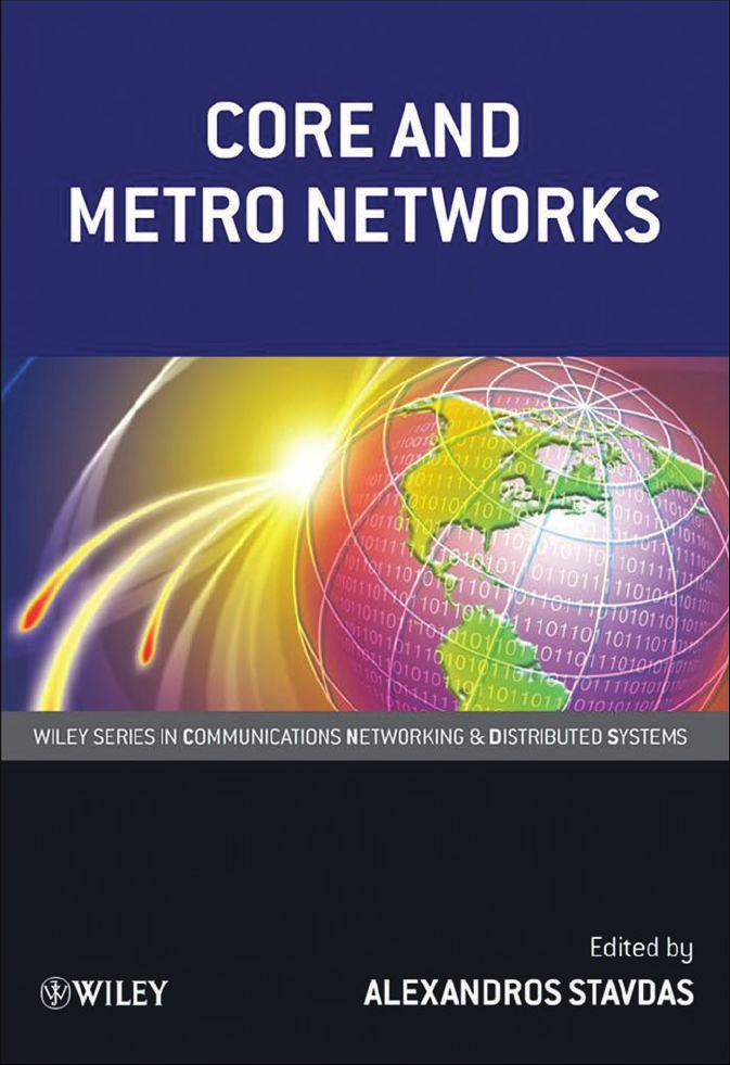
The trend imposed by the dramatic increase of packet traffic and the obvious advantages in
evolving existing circuit-switched networks into advanced packet-switched networks is going
to make PTTs a viable solution to building a unified transport infrastructure, as depicted in
Figure 1.1. Incumbent network operators that have already deployed a versatile NG-SDH
network for aggregated traffic may follow conservative migration guidelines for their core
networks and keep circuit solutions based on optical technologies. These plausible solutions
are discussed in Section 1.4.
1
facilitating to allow Ethernet attaining traffic
1
A tunnel is a method of communication between a couple of network nodes via a channel passing through intermediate
nodes with no changes in its information content.
Page 24
12 The Emerging Core and Metropolitan Networks
Figure 1.1 Unified transport network
1.3 Future Networks Challenges
1.3.1 Network Evolution Drivers
In the past decade, the proliferation of electronic and fiber-optic technologies has allowed
network services to evolve from the exclusive support of plain telephony to an abundance of
services which are transported based on the IP. These advances have had a major impact on the
drivers for network evolution.
Nowadays, network design and planning is the outcome of the interplay between different
technological, legal, and economic drivers:
.
Introduction of new services. A network operator or a service provider can decide to offer
new services based on customers’ requests or market trends.
.
Traffic growth. The growing penetration and the intensive use of new services increase the
network load.
.
Availability of new technologies. Electronic, optical, and software technologies keep on
offering new advances in transmission, switching, and control of information flows based on
circuits and packets.
.
Degree of standardization and interoperability of new network equipment. Modern
networks are very complex systems, requiring interaction of various kinds of equipment by
means of dedicated protocols. Standardization and interoperability are key requirements for
a proper integration of many different network elements.
.
Laws and regulati ons. National laws and government regulations may set limitations and
opportunities defining new business actors for network deployment and usage.
.
Market potential and amount of investments. The financial resource availability and the
potentialof the telecommunicationmarket are thekeyeconomic drivers for networkdevelopment.
1.3.2 Characteristics of Applications and Related Traffic
In this section, the association between applications and network services is presented. The
starting point of the analysis is the bandwidth requirement (traffic) of the various applications
Page 25
Future Networks Challenges 13
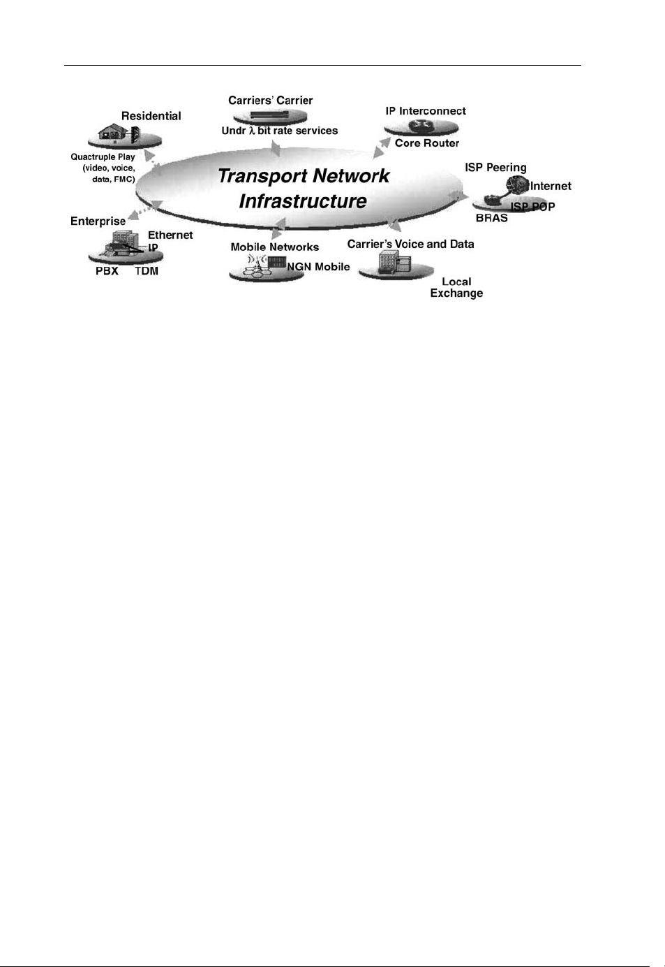
and the subsequent classification of this traffic into classes. Figure 1.2, illustrates a classification of user applications based on the following traffic characteristics:
.
elasticity
.
interactivity
.
degree of resilience (availability)
.
symmetry
.
bandwidth.
Elastic
Traffic Classes
Inelastic
non interactive
interactive
Non interactive
interactive
standard availability
high availability
standard availability
high availability
standard availability
high availability
standard availability
high availability
asymmetrical
symmetrical
asymmetrical
symmetrical
asymmetrical
symmetrical
asymmetrical
symmetrical
asymmetrical
symmetrical
asymmetrical
symmetrical
asymmetrical
symmetrical
downloding
remote backup
P2P file exchange
mail
tele-diagnostics
medical data storage
network supervision
web browsing
compute grid
telnet
data grid
utility grid
gambling
network control
low bandwidth
high bandwidth
low bandwidth
high bandwidth
low bandwidth
high bandwidth
low bandwidth
high bandwidth
radio broadcast
Live radio
video on demand
video broadcast
live TV
asynchronous mirroring
storage on demand
tele-vigilance
voice over IP
video chat
remote surgery
synchronous mirroring
real time compute grid
digital distribution
digital cinema distribution
telephony
IP telephony
gaming
video-conference
paramedic communications
emergency communications
Figure 1.2 Classification of traffic generated by reference applications
Page 26

14 The Emerging Core and Metropolitan Networks
Table 1.3 Qualitative classification of traffic types
Elastic Inelastic
Interactive Transactional Real time
Noninteractive Best effort Streaming
Elasticity refers to the level up to which the original traffic shape can be modified; the two main
categories are as follows:
.
Inelastic traffic (or stream traffic) is generated by applications whose temporal integrity
overwhelms data integrity because they try to emulate virtual presence.
.
Elastic traffic is generated by applications where data integrity overwhelms temporal
integrity, therefore being rather tolerant to delays and being able to adapt their data
generation rate to network conditions.
The term interactivity refers to a mode of operation characterized by constant feedback and
an interrelated traffic exchange between the two endpoints of the connection.
To map users’ applications traffic into the appropriate network services, it is essential to
define a few classes of traffic patterns that share the main characteristics. For this purpose,
Table 1.3 defines four kinds of traffic patterns in terms of QoS requirements.
Another important task is to assign QoS parameters quantitatively to the traffic classes.
Table 1.4 sets the values of QoS parameters used to define four basic classes as:
.
real-time traffic
.
streaming traffic
.
transactional traffic
.
best-effort traffic.
In connection with Table 1.4, the term dynamicity refers to the ability of a user to modify the
parameters of an existing connection. It is the only important parameter not described in
Section 1.2.6, since it is not addressed directly by the classic QoS definition, but it is anyway an
important quantity for application classification. The dynamicity refers to the time variation
of the following connection characteristics:
.
bandwidth (bit-rate);
.
QoS parameters (latency, availability, data integrity);
.
connectivity (the end-points of the connection).
The level of dynamicity is quantified on a three-state base:
– “none” (it is not possible to modify any parameters of an existing connection);
– “bit-rate and QoS” (when only these two parameters can be altered);
– “full” (bit-rate, QoS parameters, and connectivity modifications are allowed).
As seen in connectio n with Table 1.4, four traffic categories are defined based only on QoS
parameters. Table 1.5 shows examples of applications belonging to each one of the four classes
identified above, having different bandwidth requirements.
Page 27

Table 1.4 Quantitative classification of QoS for traffic classes
Blocking
probability (%)
Real time <0.1 >99.995 <1 <50 ms
Streaming <0.1 >99.99 <1 <1s
Transactional <1 >99.9 <3 <1s <200 Bit-rate and QoS <1 E-2
Best effort
Network
availability (%)
Set-up
time (s)
Max.
latency
Mean
latency
(ms)
Max.
latency
variation
Dynamicity Packet loss rate
Bit-rate, QoS and
<5 E-5
connectivity
None <1 E-3
Not applicable
Future Networks Challenges 15
Page 28

16 The Emerging Core and Metropolitan Networks
Table 1.5 Traffic characterization based on bandwidth (BW) and QoS parameters and map of users’
applications
QoS Low BW (tens of kbit/s) Medium BW (<2 Mbit/s) High BW (>2 Mbit/s)
Real time Legacy and IP telephony Gaming Video conference, grid
computing
Streaming UMTS Remote backup, network
supervision
Transactional E-commerce Telnet SAN
Best effort E-mail, domotic, VoIP p2p file exchange, data
acquisition
a
Video on demand.
b
Storage area network.
TV and video broadcast,
a
Vo D
b
p2p file exchange, data
acquisition
Table 1.5 is useful to map most common users’ applications into the four traffic classes (real-
time, streaming, transactional, best-effort), taking also the bandwidth use into account.
Similar to the classification of user applications, network services are classified into five
categories in association with the network services reported in Section 1.2.4. Thus, the network
service map looks as follows:
.
L1 VPN, which provides a physical-layer service between customer sites belonging to the
same closed user group. These VPN connections can be based on physical ports, optical
wavelengths, or TDM timeslots.
.
L2 VPN, which provides a service between customer terminals belonging to the VPN at the
data link layer. Data packet forwarding is based on the information contained in the packets’
data link layer headers (e.g., frame relay data link circuit identifier, ATM virtual circuit
identifier/virtual path identifier, or Ethernet MAC addresses).
.
L3 VPN, which provides a network layer service between customer devices belonging to the
same VPN. Packets are forwarded based on the information contained in the layer 3 headers
(e.g., IPv4 or IPv6 destination address).
.
Public IP, which is considered as the paradigm of best-effort network services. Namely, it is
a generalized L3 VPN without restrictions to the user group, but with a consequently poor
QoS.
.
Business IP, which is included as a higher priority class that, for instance, can efficiently
handle latency
2
in ti me-sensitive applications.
On top of this classification, further “orthogonal” categorizations are often introduced. VPN
services are further subdivided into:
– permanent VPNs, to be provided on a permanent basis by the network service
provider;
– on-demand VPNs, which could be controlled dynamically by the client user/network.
2
See latency and other QoS defining parameters later in this section.
Page 29
Future Networks Challenges 17
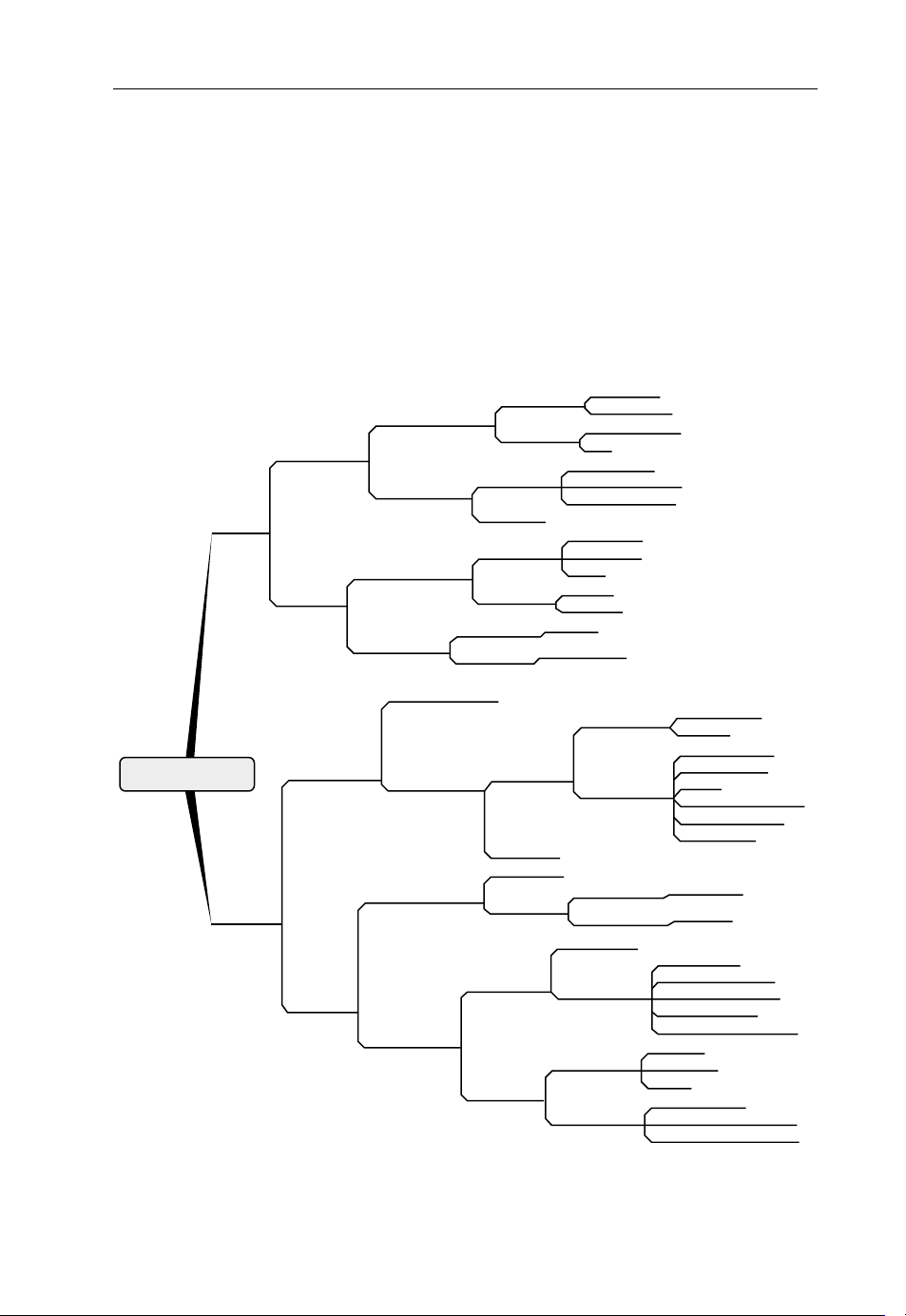
Table 1.6 Mapping network services groups to some applications (BW: bandwidth)
L1 and L2 VPN services are also classified into high- and low-availability services. Table 1.6
provides a mapping between “user applications” and “network services”: in this context,
a stippled box means that that particular application may run over on this network service, but
not very efficiently. The most efficient support to that application is designated with horizontal
rows, whereas a white box should be interpreted as no support at all from this service to that
application.
1.3.3 Network Architectural Requirements
This section gives an overview of the architectural requirements for transport networks
supporting the services described above.
1.3.3.1 Network Functional Requirements
From an architectural point of view, data services have been traditionally transported over a
wide set of protocols and technologies. For example, IP services are transported over the core
network usually relying on SDH, ATM, or Ethernet transmission networks. A widespread
alternative used in current convergent transport networks is to go towards a meshed network of
IP/MPLS routers, interconnected through direct fiber or lambda connections and without any
multilayer interaction.
This “IP-based for everything” approach was proved to be valid for the last decade, but with
current traffic trends it would lead to scalability problems. Currently, backbone nodes need
switching capacities of several terabits per second, and this need is predicted to double every
2 years. Routers are also very expensive and they are not optimized for high-bandwidth traffic
transportation, while transport technologies such as SONET/SDH are not efficient enough for
packet transport, due to a very coarse and not flexible bandwidth granularity.
Page 30

18 The Emerging Core and Metropolitan Networks
On the other hand, a number of emerging services (e.g., new multimedia applications served
over the Internet; i.e., real-time high-bandwidth video services) are imposing new requirements on the current “IP-based for everything” architecture in terms of bandwidth and QoS
(end-to-end delay and availability). Moreover, mobility of users and devices and new traffic
profiles (due to, for example, flash crowds and streaming services) require a network with an
unprecedented dynamicity that is able to support unpredictable traffic patterns.
1.3.3.2 Network Scalability
The term scalability is a feature of a network architecture designating the ability to
accommodate higher traffic load without requiring large-scale redesign and/or major deployment of resources. A typical (negative) example manifesting lack of scalability is an SDH
ring where additional resources and manual configurations are mandatory in order to increase
the capacity between two nodes. Thus, future transport networks should be scalable in order to
support existing or yet-unknown clients and traffic volumes.
The lack of scalability is demonstrated in two distinctive ways. First, by means of an
excessive deployment of network resources to accommodate higher traffic volumes. This
inefficiency is leading to higher CAPEX and OPEX that are mainly attributed to the enduring
very high cost of switching. Solving this issue requires the deployment of technologies able to
transport traffic with a lower cost per bit. Second, it is associated with architectural and/or
control plane scalability restrictions due to the excessive number of network elements to
control (e.g., the number of paths in the network). To address this issue requires the adoption
of layered architectures and aggregation hierarchies.
1.3.3.3 Network Reconfiguration Ability
Network reconfiguration ability refers to the ability of the network to change the status of some
or all of the established connections, to modify the parameters of these connections (e.g.,
modify the amount of allocated bandwidth) or to modify the way the services are provided (for
instance, changing the routing of a given connection to allow more efficient grooming on a
different route or improve spare capacity sharing).
The interest in having a reconfigurable network comes from the fact that traffic profiles
change very frequently, may be fostered by symmetrical traffic patterns, unexpected traffic
growth, possible mobile data/multimedia services, varied geographic connectivity (e.g., home,
work), andemerging services, suchas user-generated content. All these facts make it reasonable
to think in the future about a highly varying traffic profile in a network, thus meaning that
reconfigurability would be a highly advantageous characteristic in data architectures.
1.3.3.4 Cost Effectiveness
Taking into account the fierce competition and the pressure upon network operators in the
telecommunications market, as well as the descending cost per bit charged to the final user, the
only solution for service providers to keep competitive is to reduce traffic transport costs.
Therefore, cost effectiveness is the obvious requirement for any new technology. Basic
Page 31

Future Networks Challenges 19
approaches to achieve this cost reduction are to build networks upon cheap scale-economy
technologies, adapted to the applications’ bursty data traffic and specifically designed to keep
functional complexity to a minimum. To facilitate this cost per bit reduction even in presence
of unp redictable traffic growth, modular solutions are of paramount importance.
1.3.3.5 Standardized Solutions
Standardization of solutions is a key point, because it assures interoperability of equipment
from different manufacturers and, as a consequence, it allows a multi-vendor environment.
This leads to the achievement of economies of scale that lower costs, since a higher number
of suppliers use the same technology. Besides, standardization allows network operators to
deploy networks with components from different suppliers, therefore avoiding dependence on
a single manufacturer, both from a technological and an economical point of view.
1.3.3.6 Quality of Service Differentiation
As specified in Sections 1.2.6 and 1.3.2, a differentiating feature between the various
applications consists in their dissimilar transport network requirements (e.g., minimum/
maximum bandwidth, availability, security, delay, jitter, loss, error rate, priority, and buffering). For this reason, networks have to support QoS differentiation because their main goal is to
assure a proper multi-service delivery to different applications. The intention of QoS
specifications is to utilize network mechanisms for classifying and managing network traffic
or bandwidth reservation, in order to deliver predictable service levels such that service
requirements can be fulfilled.
1.3.3.7 Resilience Mechanisms
As reported in Section 1.2.5, an important aspect that characterizes services offered by
telecommunication networks is service availability. Resilience mechanisms must be present
in order to react to network failures, providing backup solutions to restore the connections
affected by the failure. Typical resilience mechanisms provide full protection against all single
failures; they distinguish in terms of how fast restoration is provided and on the amount of
backup capacity required for protection, to fully suppor t this single-failure event. Resilience
schemes can also be characterized depending on their ability to provide various level of
protection (e.g., full protection against single failures, best effort protection, no-protection, and
preemption in the case of failure) and on their capability to provide very high availability
services (e.g., full protection against multiple failures). For transport network clients, the
important aspect is the resulting service availability, measured in terms of average service
availability over a given period of time (e.g., 1 year) and of maximum service interruption time.
1.3.3.8 Operation and Maintenance
A fundamental requirement is to keep a proper control over the networking infrastructure: easy
monitoring, alarm management, and configuration tools are required. The current trend for
Page 32

20 The Emerging Core and Metropolitan Networks
OPEX reduction and maintenance simplification leads towards automated distributed cont rol
maintenance and operations.
Transport technologies or carrier-grade switching and transmission solutions differ from
other technologies in the OAM features: it is important not only in adm inistrating
and managing the network, but also to provide services and to deal with its customers.
Efficient operation tools and mechanisms must also be implemented within the transport
networks.
Finally, it is important to consider the interoperability between different network layers that
requires mutual layer independence; for this reason, the transport technology needs to be selfsufficient to provide its own OAM, independently of its client and server layers.
1.3.3.9 Traffic Multicast Support
A multicast transfer pattern allows transmission of data to multiple recipients in the network at
the same time over one transmission stream to the switches.
A network with multicast capability must guarantee the communication between a single
sender and multiple receivers on a network by delivering a single stream of information to
multiple recipients, duplicating data only when the multiple path follows different routes. The
network (not the customer devices) has to be able to duplicate data flows. There are only two
degrees for the ability to support multicast transfer: able or unable (multicast is an on/off
property).
Multicast distribution is considered a useful tool for transport technologies when dealing
with IPTV and similar applications. However, it is pointed out that layer 2 multicasting is not
the only solution to distribute IPTV.
1.3.3.10 Multiplicity of Client Signals
Previous sections highlighted that metro-core networks are supporting traffic from many
different applications, such as business data, Web browsing, peer to peer, e-Business, storage
networking, utility computing, and new applications such as video streaming, video conference, VoIP, and tele-medicine applications. The prevalence of multimedia services and the
expansion of triple-play has an important role in traffic load and distribution in metro and core
networks. A strong increase of broadband access penetration, based on a combination of
different fixed and mobile access technologies, is expected for the next years, favoring the
increase of terminal nomadism, which might introduce a more variable and unpredictable
traffic, especially in the metro area. On the other side, corporate VPN services ranging from
MPLS-based VPNs [10] to legacy services cope with the business telecom market.
From a technological standpoint, most services are migrating to packet-based Ethernet
framing. This trend makes it mandatory for Core/Metro networks to support Ethernet client
services. Nevertheless, many legacy networks are still based on other standards, such as SDH
and ATM, and they still need to suppor t these kinds of technology.
A transport infrastructure that can carry traffic generated by both mobile and fixed access is
an important challenge for future transport networks.
Fixed and mobile applications present similar QoS requirements, and can be classified
according to the four classes previously defined in Section 1.2.4. (i.e., best-effort, streaming,
Page 33

Future Networks Challenges 21
real-time, and transactional). However, current bandwidth requirements are lower for mobile
applications than for fixed applications due to limitations in wireless access bandwidth and
terminal screen size and resolution.
1.3.3.11 Transport Network Service Models and Client Interactions
Telecom networks have been upgraded with different network layer technologies, each
providing its own set of service functionality based on its own switching paradigm and
framing architecture. The GMPLS (Generalized Multi-Protocol Label Switching) protocol
architecture paves the way for a convergence between transport and client networks reducing,
thus, the overall control and management complexity. GMPLS can be configured to handle
networks with dissimilar switching paradigms (on data plane) and different network management platforms (on control and management plane). This is made feasible by means of LSPs
(Label Switched Paths) that are established between two end points. i.e. under the GMPLS
protocol architecture the resources of the optical transport network are reserved based on the
connectivity requests from a client packet-switched network.
The Overlay Model
The overlay model refers to a business model in which carriers or optical backbone
(bandwidth) providers lease their network facilities to Internet service providers (ISPs). This
model is based on a client–server relationship with well-defined network interfaces (or
automatic switched optical networ k (ASON) reference points) between the transport network
involved and client networks. The overlay model mandates a complete separation of the data
client network control (that could be IP/MPLS based) and the transport network control plane
(e.g., wavelength-switched optical networks/GMPLS). A controlled amount of signaling and
restricted amount of routing messages may be exchanged; as a consequence, the overlay model
is a very opaque paradigm. The IP/MPLS routing and signaling controllers are independent of
the routing and signaling controllers within the transport domain, enabling the different
networks to operate independently. The independent control planes interact through a userto-network interface (UNI), defining a client–server relationship between the IP/MPLS
data network and the wavelength-switched optical network (WSON)/GMPLS transport
network.
Overlay network service models support different business and administrative classes
(as developed in Section 1.5.3.) and preserve confidentiality between network operators. The
connection services are requested from client networks to the transport network across distinct
UNIs. When a connection is established in the transport network for a given client network,
this connection can be used as a nested LSP or a stitched LSP to support the requirements of the
client network.
The service interface in the overlay network model can be configured according to the level
of trust of the two interacting structures. The interface can be based on a mediation entity such
as an operation service support (OSS) or it can use the northbound interface of the network
management system. Further, the interface between client network (higher layer network) and
transport network (lower layer network) can operate a GMPLS signaling protocol, such
reservation protocol with TE (RSVP-TE).
Page 34

22 The Emerging Core and Metropolitan Networks
Peer Model
Compared with the overlay model, the peer model is built on a unified service representation,
not restricting any control information exchanged between the transport network and the
clients. This model is relevant and represents an optimal solution when a transport network
operator is both an optical bandwidth provider and an ISP. In this case, the operator can
optimally align the virtual topologies of its transport network with the network services
required by its data network. The IP/MPLS control plane acts as a peer of the GMPLS transport
network control plane, implying that a dual instance of the control plane is running over the data
network (say, an IP/MPLS network) and optical network (say, a WSON/GMPLS network).
The peer model entails the tightest coupling between IP/MPLS and WSON/GMPLS components. The differentnodes are distinguished by their switching capabilities; for example, packet
for IP routers interconnected to photonic cross-connects (PXCs).
Integrated Model
Compared with the peer model, the integrated model does not require different service
interfaces between the different networks. The integrated model proposes the full convergence
of data network control plane and transport network control plane. All nodes are label-switched
routers (LSRs) all supporting several switching capabilities; say, wavelength, SDH and
Ethernet. Each LSR is also able to handle several orders of the same switching capability
as it happens; for example, with SDH. An LSR embeds one GMPLS control plane instance and
is able to control simultaneously different switching capability interfaces. Only this model can
handle a complete and global optimization of network resource usages through transport and
client networks.
Augmented Model
The augmented model considers that the network separation offered by the overlay model
provides a necessary division betwee n the administrative domains of different network service
providers, but also considers that a certain level of routing information should be exchanged
between the transport network and the client networks. In a competitive environment, a
complete peer network service model is not suitable because of the full exchange of topology
information and network resource status between client and server optical networks, imposing
on a network operator to control the resources of the client data networks and triggering the
scalability issues of the management functions.
The augmented model provides an excellent support for the delivery of advanced connectivity services as might be offered from a multilayer network (MLN)/multiregion network
(MRN). The capability, such as wavelength service on demand, integrated TE or optical VPN
services, can require controlled sharing of routing information between client networks and
the optical transport network.
User-to-network Interface
The UNI is a logical network interface (i.e., reference point) recommended in the
“Requirements for Automatic Switched Transport Network” specification ITU-T
G.807/Y.1302. The UNI defines the set of signaling messages that can be exchanged between
a client node and a server node; for instance, an IP router and an SDH optical cross-connect
(OXC) respectively. The server node provides a connection service to the client node; for
example, the IP router can request TDM LSPs from its packet over SONET (PoS) interfaces.
The UNI supports the exchange of auth entication, authorization, and connection admission
Page 35

Future Networks Challenges 23
control messages, and provides the address space set of the reachable nodes to the client
network. Different versions of the implementation agreement for a UNI have been produced
by the Optical Internetworking Forum (OIF) since October 2001 as OIF UNI 1.0. The different
OIF implementation agreement versions are supporting the overlay service model as well as the
augmented service model. The signaling messages exchanged between the client node and
the server node are focused on the LSP connection request, activation, deactivation, and tear
down. The IETF specifies a GMPLS UNI that is also applicable for a peer model. Fully
compliant with RSVP-TE, GMPLS UNI allows the end-to-end LSP handling from the ingress
customer edge equipment to the egress customer edge equipment and at each intermediate LSR
involved in the signaling sessions.
Network-to-network Interface
The network-to-network interface (NNI) is a logical network interface (i.e., reference point)
recommended in the “Requirements for Automatic Switched TransportNetwork” specification
ITU-T G.807/Y.1302.The NNI defines the set of both signaling messages and routing messages
that can be exchanged between two network server nodes; for example, SONET OXC and SDH
OXC. There are two types of NNI, one for intranetwork domains and one for internetwork
domains: an external NNI (E-NNI) and an internal NNI (I-NNI) respectively.
.
The E-NNI assumes an untrusted relationship between the two network domains. The
routing information exchanged between the two nodes located at the edge of the transport
Figure 1.3 Customer nodes to public network link through server nodes by the UNI as defined in ITU
architecture
Page 36

24 The Emerging Core and Metropolitan Networks
network specified within the E-NNI is restricted. The control messages exchanged include
reachable network addresses that are usually translated, authentication and connection
admission control messages, and a restricted set of connection requests of signaling
messages.
.
The I-NNI assumes a trusted relationship between two network domains. The control
information specified within the I-NNI is not restricted. The routing control messages
exchanged include topology, TE link state, and address discovery. The signaling messages
can allow controlling of the resources end to end between several network elements and
for each LSP and its protection path.
1.3.4 Data Plane, Control Plane, and Management Plane Requirements
1.3.4.1 Data Plane Requirements
The challenges of the physical layer part of the data plane are covered in Chapters 3–6. In this
section, two conceptual challenges of the data plane are addressed, namely the quest for
transparency and the search for novel transport formats.
Transparency
During the last 20 years the cornerstone of transport network evolution has been the notion
of “transparency.” Today, there are two distinctive understandings of the term “transparency”:
bit-level transparency and optical transparency.
In the original idea, the two meanings were synonymous and they were based on the
following simple concept. The advent of the erbium-doped fiber amplifier facilitated the
proliferation of WDM (these topics are discussed in Chapters 3–6), which increased
the product “bandwidth times length” to about two to three orders of magnitude, an event
that eventually led to a significant curb of the transmission cost. As a result of this evolution, the
cost of switching started dominating (and still does) the cost of a transport network. At the same
time, there was a clear disparity between the data throughput that the fiber-optic systems could
transmit and the amount of data that synchronous systems (SDH/SONET) could process,
a phenomenon that was termed an “optoelectronic bottleneck.” For these reasons, every effort
was made to minimize electronic switching wherever possible, making use of opticalbypassing concepts for the transit traffic, namely avoiding transport schemes requiring frequent
aggregation and grooming of the client signals through electronic switches.
The widespread deployment of applications based on the IP and the emergence of a “zoo”
of other protocols (like Ethernet, ESCON, Fiber Channel, etc.) gave a renewed impetus to
incentivize transparency in transport networks.
In mor e recent times, transparency went colored of different shades.
Bit-level Transparency
The transport network (OTN in particular) should convey client signals with no processing
of the information content. This will minimize the aggregation/grooming used throughout the
network, whilst it will provide a client/provider agnostic transportation (transparent bitmapping into the transport frame). Here, transparency mainly indicates service transparency;
that is, the minimization of bit-by-bit processing regardless of the technological platform that
is used. This definition is shifting the interest from technologies to functions; hence, both
Page 37

Future Networks Challenges 25
all-optical and optoelectronic subsystems are of equal interest in building service-transparent
networks.
Optical Transparency
Nevertheless, in conjunction with bit-level transparency, the initial notion of a transparent
network is still of interest, where the optical/electrical/optical (O/E/O) conversions are
minimized so the signal stays in the optical domain. The benefits from the reduc tion in the
number O/E/O conversions include:
.
reduction of a major cost mass by minimizing the number of transponders and large (and
expensive) switching machinery;
.
improved network reliability with a few in number of electronic systems;
.
significant reduction in power consumption (from switching fabrics to cooling
requirements).
In an optically transparent network, the routing of the sign al is based on the wavelength
and/or on the physical port of the signal. Framing takes place at the ingress to the optically
transparent domain and it adds overhead information that makes it possible to detect errors –
possibly occurring during transmission – at the egress node. Each standardized format has a
specific frame, and several different frames are possible at the ingress to an optically
transparent domain; for example, Ethernet frames, synchronous transport module frames,
and G.709 [11] frames.
Ethernet as an Alternat ive Transport Platform
Ethernet is a frame-based technology that was defined in 1970s. It was originally designed for
computer communications and for broadcasting, and since then it has been widely adopted.
This was made possible thanks to two main competitive advantages. First, a successfully
implemented switching capability besides the original broadcasting LAN technology. Second,
because all generations of Ethernet share the same frame formats, making it feasible to support
interfaces from 10 Mbit/s over copper to 100 Gbit/s over fiber (the latter still under standardization), thus ensuring seamless upgra deability.
Nowadays, Ethernet represents the most successful and widely installed LAN technology
and is progressively becoming the preferred switching technology in metropolitan area
networks (MANs). In the latter scenario, it is used as a pure layer 2 transport mechanism,
for offering VPN services, or as broadband technology for delivering new services to
residential and business users. Today, Ethernet traffic is rapidly growing and apparently it
has surpassed SDH traffic. As mentioned in the previous section, bit transparent mapping is
essential for a cost-effective transportation of data and it is a feature provided by Ethernet
thanks to its framing format. As Ethernet is becoming the dominant technology for service
provider networks and as 40/100 GbE interfaces will be standardized in the years to come, it is
essential to keep Ethernet transport attractive and simple. Currently, under the Ethernet
umbrella, three network layers are considered:
.
Network layer, based on Metro Ethernet Forum (MEF) documents. The network services
include E-Line, defining point-to-point connections, and E-LAN, defining multipointto-multipoint connections and rooted multipoint connections.
Page 38

26 The Emerging Core and Metropolitan Networks
.
Layer 2, which is also called the MAC layer. This provides network architectures, frame
format, addressing mechanisms, and link security (based on IEEE 802.1 and IEEE 802.3).
.
Physical layer, which includes the transmission medium (e.g., coaxial cable, optical fiber),
the modulation format, and network basic topologies (based on IEEE 802.3).
The numerous networks where Ethernet is installed confirm that it is a valuable frame-based
technology, capable of assuring an inexpensive physical stratum, providing high bit-rates, and
allowing network architectures to offer emerging network services for distributing both pointto-point and p2mp variable bit-rate traffic efficiently.
There are several initiatives at standardization bodies that aim at a revision of Ethernet to
make it valuable and deployable in transport networks. The work carried out at IEEE, IETF,and
ITU-T is improving Ethernet with faster and more efficient resilience mechanisms and valuable
OAM tools for fault localization and measurement of quality parameters to verify customers’
service level agreements (SLAs).
Given this success in the access area and MAN and the simplicity and transparency it offers,
Ethernet is stepping forward to the core network segment under the definition of carrier
Ethernet which is investigated by the MEF as “a ubiquitous, standardized, carrier-class Service
and Network.” Carrier Ethernet improves standard Ethernet technology facing scalability
issues (assuring a granular bandwidth increment from 1 Mbit/s to 10 Gbit/s). It also assures
hard QoS mechanisms (allowing the transport on the same lambda of different traffic
categories) and reliability (the network is able to detect and recover from failures with
minimum impact on users). Carrier Ethernet aims to achieve the same level of quality,
robustness, and OAM functions typical of circuit technologies (think of SDH or OTN) while
retaining the Ethernet advantage in offering a cost-effective statistical aggregation.
1.3.4.2 Control Plane Requirements
The control plane is studied in detail in Chapter . Here, some important issues are highlighted.
Provisioning of End-to-end Connections over the Entire Network
The main function of the control plan e is to set up, tear down, and maintain an end-to-end
connection, on a hop-by-hop basis, between any two end-points. The applications supported
from the transport network have specific QoS require ments (Section 1.2.6), which the control
plane must uphold.
Unified Control Plane
In the quest to upgrade or build new integrated network infrastructures, a paradigm shift has
been witnessed in network design principles. The focus has shifted from a layered-network
model involving the management of network elements individually at each layer, to one of
an integrated infrastructure able to provide a seamless management of packets, circuits, and
light paths. The reasons for this industry trend towards a unified set of mechanisms (the
unified control plane), enabling service providers to manage separate network elements in a
uniform way, can be traced to the historical evolution of transport and packet networks. The
IP became the uncontested platform for supporting all types of application and the
associated, IP-based, GMPLS provides a single, unified control plane for multiple switching
layers [12].
Page 39

Future Networks Challenges 27
Horizontal Integration (Unified Inter-domain Control)
This issue refers to the way of multidomain interconnection at control plane level. Horizontal
integration refers to the situation where, in the data plane, there is at least one common
switching facility between the domains, whilst the control plane topology extends over several
domains. For instance, the control plane interconnection between lambda-switching-capable
areas defines a horizontal integration.
Control Plane and Manage ment Plane Robustness
In the emerging optical network architectures, the interplay between the control plane and
management plane is essential to ensure fast network reconfiguration, while maintaining the
existing features of SDH/SONET like robustness against failures, which is essential for the
preservation of traffic continuity.
Network Autodiscovery and Control Plane Resilience
Automated network discovery refers to the ability of the network to discover autonomously
the entrance of new equipment or any changes to the status of existing equipment. This task is
assigned to the control plane. Additional functions of the control plane are the automated
assessment of link and network load and path computation process needed to substantially
reduce the service provision time and the changes invoked in the network infrastructure to
support these services. Moreover, the automation is essential to reallocate resources: as
customers cancel, disconnect, or change orders, the network resources can be readily made
available to other customers.
The term control plane resilience refers to the ability of the control plane to discover the
existing cross-connect topology and port mapping after recovering from a failure of itself.
For example, when only control plane failures occur within one network element, the
optical cross-connects will still be in place, carrying data traffic. After recovery of the control
plane, the network element should automatically assess the data plane (i.e., optical crossconnects), and reconfigure its control plane so that it can synchronize with other control plane
entities.
Appropriate Network Visibility among Different Administrative Domains
Belonging to Different Operators
Administrative domains may have multiple points of interconnections. All relevant interface
functions, such as routing, information exchanges about reachable nodes, and interconnection
topology discovery, must be recognized at the interfaces between those domains. According to
ASON policy, the control plane should provide the reference points to establish appropriate
visibility among different administrative domains.
Fast Provisioning
As part of the reliable optical network design, fast provisioning of optical network connections
contributes to efficient service delivery and OPEX reduction, and helps reaching new
customers with broadband services.
Automatic Provisioning
To achieve greater efficiencies, optical service providers must streamline their operations by
reducing the number of people required to deliver these services, and reducing the time
required to activate and to troubleshoot network problems. To accomplish these objectives,
Page 40

28 The Emerging Core and Metropolitan Networks
providers are focusing on automated provisioning through a distributed control plane, which is
designed to enable multi-vendor and multilayer provisioning in an automated way. Therefore,
requests for services in the data network that may require connectivity or reconfiguration at
the optical layer can happen in a more automated fashion. In addition, instead of provisioning
on a site-by-site basis, the control plane creates a homogeneous network where provisioning is
performed network-wide.
Towards Bandwidth On-demand Services
Providers can also set up services where the network dynamically and automatically increases/
decreases bandwidth as traffic volumes/patterns change. If the demand for bandwidth increases
unexpectedly, then additional bandwidth can be dynamically provisioned for that connection.
This includes overflow bandwidth or bandwidth over the stated contract amount. Triggering
parameters for the change may be utilization thresholds, time of day, day of month, perapplication volumes, and so on.
Bandwidth on demand (BoD) provides connectivity between two access points in a nonpreplanned, fast, and automatic way using signaling. This also means dynamic reconfiguring of
the data-carrying capacity within the network; restoration is also consider ed here to be a
bandwidth on-demand service.
Flexibility: Reconfigurable Transport/Optical Layer
A network operator may have many reasons for wanting to reconfigure the network, primarily
motivated by who is paying for what. Flexibility of the transport layers means a fair allocation
of bandwidth between competing routes dealing with bursts of activity over many timescales.
Reconfigurability increases network flexibility and responsiveness to dynamic traffic demands/
changes.
1.3.4.3 Interoperability and Interworking Requirements
Multidomain Interoperability
In many of today’s complex networks, it is impossible to engineer end-to-end efficiencies in
a multidomain environment, provision services quickly, or provide services based on real-time
traffic patterns without the ability to manage the interactions between the IP-layer functionality of packet networks and that of the optical layer. Accordi ng to proponents of ASON/
GMPLS, an optical control plane is the most advanced and far-reaching means to control these
interactions.
Another important issue is that of translating resilience classes from one domain to another.
The ASON reference points UNI and I-NNI/E-NNI are abstracted functional interfaces that can
resolve that topic by partitioning the transport network into sub-networks and defining
accurately the exchanges of control information between these partitions. As recommended
in Ref. [13], the UNI is positioned at the edge of the transport network as a signaling interface
used by the customer edge nodes to request end-to-end connection services between client
networks, with the explicit level of availability. Routing and signaling messages exchanged at
the I-NNI concern only the establishment of connections within a network domain or across the
subnetwork. The E-NNI is placed between network domains or sub-networks to carry the
control message exchanges between these regions of different administration.
Page 41

Future Networks Challenges 29
Multi-vendor Interoperability
The multi-vendor interoperability of metro and core solutions maximizes carrier performance
and ensures the interoperability of legacy with emerging network architectures. One of the
most important objectives of the development of a standardized ASON/GMPLS control plane
is to contribute to interoperability, which validates the speed and ease of provisioning enabled
by ASON/GMPLS in a live, multi-vendor network.
Seamless Boundary in between Networks
Given the vast amount of legacy SONET/SDH equipment, there is a clear need for an efficient
interworking between traditional circuit-oriented networks and IP networks based on the
packet-switching paradigm. For example, efficient control plane interworking between
IP/MPLS and SONET/SDH GMPLS layers is indispensable and requires the specification
of their coordination.
1.3.4.4 Management Plane Requirements
Easy-to-use Network
Emerging standards and technologies for optical networks allow for a significantly simplified
architecture, easy and quick provision of services, more effective management, better
interoperability and integration, and overall lower cost. In addition, it will be possible to
provision services on these future networks such that global applications will be much more
location independent.
Transparent for Applications: Hide Network Technology to Users
There are multiple separate service, technology, and technical considerations for networks
depending on location, at the metro edge, metro core, aggregation points, long haul, and ultralong haul. Next-generation optical networking has the potential to reduce significantly or
eliminate all of these barriers, especia lly with regard to application and end users.
To some degree, one of the key goals in this development is to create network services with a
high degree of transparency; that is, allow networ k technical elements to become “invisible”
while providing precise levels of required resources to applications and services. To allow an
optimal use of the optical network infrastructure interconnecting different types of application,
network service management functions are required to establish automatically connection
services with adequate amount of allocated network resources. The network service man agement layer can rely on the routing and signaling control functions.
Monitoring of End-to-end Quality of Service and Quality of Resilience
The requirement of integrated monitoring of the (optical) performance of connections, QoS,
and fault management speeds up system installation and wavelength turn-up and simplifies
ongoing maintenance. Furthermore, the management plane should be able to monitor endto-end quality of resilience. That means the end-to-end type of transport plane resilience
parameters (such as recovery time, unavailability, etc.) should be monitored and adhered
according to the SLAs).
Connectivity and Network Performance Supervision
As networks run faster and become more complex, infrastructure, links, and devices must
operate to precise levels in a tighter performance. As a result, a huge number of network
Page 42

30 The Emerging Core and Metropolitan Networks
problems stem from simple wiring and connection issues. Connectivity and performance
supervision is at the heart of an efficient network management.
Network Monitoring
A monitoring system is dedicated to the supervision of the physical and optical layers of a
network. Optical-layer monitoring should provide valuable, accurate information about the
deterioration or drift with slow and small signal variations, helping to detect problems before
they may become so serious to affect the QoS. It helps maintain the system from a lower layer’s
perspective.
Policy-based Management (Network and Local-basis)
Today’s optical network architectures lack the proper control mechanisms that would interact
with the management layer to provide fast reconfiguration. The problem of accurate intradomain provisioning in an automated manner allows satisfying the contracts with customers
while optimizing the use of network resources. It is required that a policy-based management
system dynamically guides the behavior of such an automated provisioning through the control
plane in order to be able to meet high-level business objectives. Therefore, the emerging policybased management paradigm is the adequate means to achieve this requirement.
End-to-end Traffic Management (Connection Admission Control,
Bandwidth Management, Policing)
Traffic managem ent features are designed to minimize congestion while maximizing the
efficiency of traffic. Applications have precise service requirements on throughput, maximum
delay, variance of delays, loss probability and so on. The network has to guarantee the required
QoS. For instance, the prima ry function of the connection admission control is to accept a
new connection request only if its stated QoS can be maintained without influencing the QoS
of already-accepted connections. Traffic man agement features are key elements in efficient
networking.
Multi-vendor Interoperability
In the near future, network element management interfaces and OSS interfaces will be preintegrated by control plane vendors. Indeed, independent control planes increase the performance of network elements and OSS, and reduce carriers’ reliance on any single network
element or OSS application. This eliminates the task of integrating new network elements into
a mass of OSS applications.
Connection services (respectively, connectivity services) are described from the network
infrastructure operator (respectively, the service customer) point of view, which is complementary for the connections implemented through the control functions at customer edge (CE)
nodes. Provider VPN services offer secure and dedicated data communications over telecom
networks, through the use of standard tunneling, encryption, and authentication functions.
To reconfigure automatically the provisioning of VPNs, automated OSS functions are required
to enhance existing network infrastructures for supporting networked applications sharing the
optical infrastructures.
Network service functions can automatically trigger addition, deletion, move, and/or change
of access among user sites. The description of each connection service includes the UNI
corresponding to the reference point between the provider edge (PE) node and CE node. At a
Page 43

New Transport Networks Architectures 31
given UNI, more than one connection can be provisioned from the network management
systems or automa tically signaled from the control plane functions according to multiplexing
capabilities. GMPLS controllers enable signaling of the connection establishment on demand,
by communicating connectivity service end-points to the PE node. This operation can be
assigned to an embedded controller to exchange the protocol messages in the form of RSVP-TE
messages.
Support Fixed–Mobile Convergence
Fixed-mobile convergence means alliance of wired and wireless services and it is referring to
single solutions for session control, security, QoS, charging and service provisioning for both
fixed and mobile users. Fixed-mobile convergence is clearly on the roadmap of operators that
want to create additional revenue streams from new value-added services.
1.4 New Transport Networks Architectures
Today’s telecommunication networks have evolved substantially since the days of plaintelephony services. Nowadays, a wide variety of technologies are deployed, withstanding a
substantial number of failures, supporting a broad range of applications based on diversified
edge-user devices; they span an enormous gamut of bit-rates, and they are scaling to a large
number of nodes.
In parallel, new services and networking modes (e.g., peer-to-peer) are emerging and
proliferating very rapidly, modifying the temporal and spatial traffic profile in rather unpredictable ways. As has been discussed in the previous sections, it is widely recognized that the
existing mind-set for the transport network architecture largely fails to accommodate the new
requirements. However, the bottleneck is not only on the technology front. Architectural
evolution presupposes a consensus between the many providers which, quite often, is hard to
reach. This situation is exacerbating interoperability issues that, potentially, negate any
competitive advantage stemming from architectural innovation. Market protectionism could
stall technological advances.
Nevertheless, a major rethinking on network architectures is mandatory in the quest for a
cost-effective, secure, and reliable telecommunications network. The research today is pivoted
around notions on how network dynamicity can be significantly enhanced, how the cost of
ownership can be reduced, and how the industrial cost of network services can be decreased.
The scope of this section is to present plausible scenarios for the evolution of the core and the
metropolitan transport networks, taking into account the data plane as well as the control/
management planes. It is organized so as to provide snapshots of the current situation in both
segments and for three discrete time plans:
.
short term (2010)
.
medium term (2012)
.
long term (2020).
Figure 1.4 depicts the existing network architecture for metro/regional and core/backbone
segments, which will be the starting point in the network evolution scenario. Today, the
functionality requirements are dissimilar in the two network segments, leading to the adoption
of different solutions, as was shown in Figure 1.3:
Page 44

32 The Emerging Core and Metropolitan Networks
Figure 1.4 Existing metro and core network architecture
.
In an MAN, the client traffic is transported from a “zoo” of protocols (IP, Ethernet, ATM,
SDH/SONET, ESCON, Fiber channel, etc., to mention the most import ant instances only)
whilst it is characterized from a low level of aggregation and grooming; this a problem
exacerbated by the coexistence of unicast (video on demand, high-speed Internet and voice
services) and multicast traffic (i.e., mainly IPTV). This environment postulates a highly
dynamic networking, making packet-oriented solu tions a necessity.
.
In the core network, on the other hand, the efficient aggregation and grooming out of the
MAN indicates a smoothed-out, slowly varying traffic profile, so that a circuit-switched
solution is a good candidate for a cheaper switching per bit. These developments, for the core,
are beefed up by the past and current developments of dense WDM (DWDM) and OTN
technologies, to enhance the “bit-rate times distance” product significantly, by two to three
orders of magnitude, compared to what was feasible in late 1980s, by shifting to transmission
the balance for a lower cost per bit transportation.
Regarding the scenarios presented in the rest of this section, it is pointed out that their
common denominator is progress in the following enablers:
.
Packet technologies (in particular IP/MPLS and Ethernet) for a more efficient use of
bandwidth due to the subsequent statistical multiplexing gains; that is, advanced aggregation
and grooming.
.
Control plane (currently dominated by ASON and GMPLS, which are further discussed
in Chapter ) to decrease the cost of provisioning dramatically and the possibility to have onthe-fly resilience mechanisms.
.
Optical transparency, which, as explained in Section 1.3.4.1, aims at minimizing the level
of bit-by-bit processing, simplifying client signal encapsulation, leading to transparent
Page 45

New Transport Networks Architectures 33
bit-mapping in the transport frame and providing optical bypassing for the transit traffic.
These are key functions for a reduction in CAPEX and OPEX.
As it emerges from simple inspection of the existing network architecture paradigm,
efficiency and robustness today are achieved from the interplay between two, rather mutually
exclusive, technologies: packets (mainly IP/MPLS and Ethernet) and circuits (SDH/SONET,
OTN and WDM) do coexist in transport networks with a low level of interoperability and
significant functionality duplication. Apparently, for an overall optimization, it is fundamental
to increase the synergy between the layers and reduce the unnecessary functionalityduplication.
Thus, the emerging technologies (PTTs, see Section 1.2.9), which are in the standardization
process, aim at combining the best features from both circuit and packet worlds. Therefore,
features like OAM and control plane and resilience mechanisms are inherited from the circuit
transportnetwork, whileframe format, statistical aggregation, and QoS supportare similar to the
corresponding features of packet technologies. Within the standardization bodies, two main
technologies are currently under discussion: PBB-TE (IEEE802.1Qay [14] based on Ethernet)
and MPLS-TP (developed in the ITU-T and IETF, starting from MPLS).
1.4.1 Metropolitan Area Network
The introduction of triple-play applications (voice, video, and high-speed Internet) has a
strong impact on Metropolitan Area Network (MAN) traffic. The advances include improvements in residential access networks (whose traffic aggregates upwards to the MAN),
multimedia distribution (which is using MANs in an intensive way) from points of presence
point of presence (PoPs) to the home, and finally VPNs that are used for business and
residential applications. The necessity to provide multicast services (i.e., to carry IPTV) and to
add/release users to multicast groups very quickly is a strong driver towards packet solutions
(IP, Ethernet, ATM, ESCON, Fiber channel, etc.).
In the MAN segment, the main advantages of cir cuits (low cost per switched bit per second,
strong OAM, and efficient resilience mechanisms) are not essential: the bandwidth at stake is
not really huge and the distances of the cables interconnecting the nodes are not very long,
so that the probability of failure due to fiber cut is not that high to mandate a circuit-switched
level of resilience.
However, using IP over Ethernet or pure Ethernet over WDM systems (architectural
examples are available in Ref. [15]) presents some problems in terms of resilience, bandwidth
guarantee, and OAM, because packet technologies currently do not have efficient mechanisms
to cope with such functions. For these reasons, technologies with the ambition to couple circuitlike OAM and resilience mechanisms with packet-like flexibility, dynamicity, and granularity
might represent the right candidates for next-generation networks.
Both the emerging PTTs (PBB-TE and MPLS-TP) currently have a lack of multicast traffic
that, at the date of writing (July 2008), is still under study.
Figure 1.5 shows the possible evolution of the architecture for networks in the MAN or
regional segment. The following sections describe in depth the concepts illustrated in this
picture. At the moment, the most plausible scenario is a migrations towards technologies
that, from one side, assure packet granularity and, from the other side, have “circuit-like” OAM
Page 46

34 The Emerging Core and Metropolitan Networks
current scenario
short term scenario
mid-long term scenario
DeviceServices
data
voice
IPTV
ETH
e2e
PTT
services
G707
G709
leased line
lambda
IEEE802.1AD
SDH
IEEE802.1q
ETH int
IP/MPLS
ETH int
IEEE802 1ah
xWDM
dark fiber
PBB-TE
ETH ETH
T-MPLS
OTN
IP/MPLS
router
Ethemet
switch
PTT
device
circuit
device
optical
system
Figure 1.5 Evolution scenario for metropolitan/regional network architecture
and resilience mechanisms (capabl e of switching in times shorter than 50 ms after failure,
a performance requested by the majority of applications).
1.4.1.1 Short Term
In the short term, there will probably be a progressive migration of fixed and mobile services to
IP. This migration will speed up the increasing interest towards the Ethernet technology [16].
So, the roll out of native Ethernet platforms in the metro space is likely to start in the next time
frame. Metro network solutions in the short term are expected to be mainly based on the
Ethernet technology in star or ring topologies.
Nevertheless, in this phase, both packet (IP and Ethernet) and circuit (for the most part SDH)
will coexist. In most cases, different kinds of traffic (with different quality requirements) will be
carried on the appropriate platform (e.g., voice or valuable traffic) on SDH and the remainder
on packet platforms.
No unified control plane is available for the transport layers. Further, the control plane is
restricted to a single network domain and in most cases to a single layer within the network.
1.4.1.2 Medium Term
In the metro network, Ethernet will probably be the dominant technology in the medium-term
scenario. The utilization of Ethernet is mainly driven by Ethernet conformal clients; however,
non-Ethernet payloads, such as TDM, ATM, and IP/MPLS, will still exist for a long time and
have to be adapted into an Ethernet MAC frame.
Page 47

New Transport Networks Architectures 35
Therefore, any incoming non-Ethernet payload behaves as an Ethernet payload from a
network perspective; the reverse operation is performed at the outgoing interface of the egress
network node.
Since Ethernet networks are growing in dimension, moving from simple LAN or basic
switched networks (e.g., in a campus behavior) towards a situatio n where an entire metropolitan (or regional) area is interconnected by an Ethernet platform, hundreds of thousands (or even
millions) of MAC addresses would have to be learned by the switches belonging to the metro
networks. To prevent this severe scalability problem, IEEE 802.1ah (PBB or MACinMAC)
might be adopted. This evolution of the classical Ethernet allows layering of the Ethernet
network into customer and provider domains with complete isolation amo ng their MAC
addresses.
Leaving the SDH technology, the main problems that still remain are related to the lack of
efficient resilience mechanisms, present in SDH, but not mature with IP or Ethernet. In fact,
traditional Ethernet (802.1q, 802.1ad, and 802.1ah) bases resilience on the “spanning tree”
mechanism and its evolutions (for instance, VLAN spanning tree), which are inefficient for
carrying traffic that has strong requirements in terms of unavailability.
The same argument might be argued if resilience is demanded at the IP level. In this case,
routing protocols (e.g., open short path first, intermediate system to intermediate system)
after a failure rearrange routing tables on surviving resources; also, this process assures
stability after some seconds, a time that is often too long for voice or some video
applications.
Innovative solutions to this problem might be represented by resilient packet ring (RPR) or
optical circuit switching (OCS) rings. OCS rings are specially adapted to metro–core scenarios,
as well as to metro access characterized by high-capacity flows between nodes (e.g., business
applications and video distribution services), while RPR and dual bus optical ring network
solutions fit better in scenarios with higher granularity and lower capacity requirements per
access node.
At control plane level, the most important aspects that are expected for the medium-term
scenario are the implementation of interfaces to make possible the exchange of information
(routing and signaling) between control planes even between different domains and finally the
vertical integration of the control planes of layer 1 and layer 2 technologies.
1.4.1.3 Long Term
The metro segment is composed of metro PoPs (GMPLS-capable LSR), some of which link the
metropolitan network to the IP/optics core backbone (core PoP).
In this phase, the solutions based on Ethernet technology (that is, on 802.1ah (MACinMAC)
and the IP/MPLS routing) will probably be replaced by innovative PTTs.
These technologies (MPLS-TP and PBB-TE) are connection-oriented transport technologies based on packet frames, enabling carrier-class OAM and fast protection. IP/MPLS should
remain at the edge of the network (e.g., in the access), while the metro-core will be dominated
by packet transport.
The reasons for a migration towards packet transport are a very efficient use of the bandwidth
(due to the packet behavior of the connection) joint to OAM and resilience mechanisms
comparable in efficiency to what is standardized in circuit-based networks.
Page 48

36 The Emerging Core and Metropolitan Networks
In addition, PTTs keep the door open to the introduction of a fully integrated ASON/GMPLS
network solution, which seems to be one of the most interesting approaches to meet network
emerging requirements, not only overcoming the four fundamental network problems (bandwidth, latency, packet loss, and jitter) for providing real-time multimedia applications over
networks, but also enabling flexible and fast provisioning of connections, automatic discovery,
multilayer TE, and multilayer resilience, all based on an overall view of the network status.
1.4.2 Core Network
Consistent with the metro/regional description, Figure 1.6 depicts a possible migration trend
for the architecture of the backbone network.
The current network architecture, depicted in the left side of the figure, is influenced by the
long-distance traffic relationships that are currently covered by two networks: an IP/MPLS
network (based on routers) and a transmission network based on optical digital cross-connects
(in SDH technology).
In a first phase, the evolution is represented by the migration from legacy SDH to an OTN
(based on ITU-T G.709 and its evolution); in parallel, Ethernet interfaces as routers’ ports will
substitute PoS ports. The next phase will be characterized by the adoption of PTTs for
providing connectivity and substituting pass-through routers.
The following sections describe more deeply the concepts summarized in the figure.
1.4.2.1 Short Term
In the backbone segment, for an incumbent operator, the dominance of SDH carried on DWDM
systems will be confirmed in the near future.
mid-long term scenario
PBB-TE
ETH ETH
T-MPLS
OTN
DeviceServices
IP/MPLS
router
Ethemet
switch
PTT
device
circuit
device
optical
system
data
voice
IPTV
ETH
e2e
PTT
services
G707
G709
leased line
lambda
fiber
current scenario
Pos
SDH OT N
short term scenario
IP/MPLS
ETH int
ETH
xWDM also (flexible)
dark fiber
Figure 1.6 Evolution scenario for core/backbone network architecture
Page 49

New Transport Networks Architectures 37
No unified control plane is available for the transport layers, yet. Furthermore, the control
plane is restricted to a single network domain and in most cases to a single layer within the
network.
Single-layer TE and resilience mechanisms will be still in use for quite a while. The full
standardization of the ASON/GMPLS control plan e is not yet complete. However, some
vendors already provide optical switches equipped with a standard or proprietary implementation of the GMPLS control plane and make feasible control-plane-driven networking
using the overlay network model. This suggests that the automatic switched transport network
architecture using GMPLS protocols is being implemented and deployed together with
different releases of the UNI and NNI.
1.4.2.2 Medium Term
In the core network, standard SDH (and to some extent OTH) is being introduced. The support
for Ethernet-based services is increased. The use of the native Ethernet physical layer as layer 1
transport in the core will most likely depend on the availability of OAM functionality.
With the introduction of an intelligent SDH and OTH network layer, service providers can
achieve significant cost savings in their backbones. IP over static L1 networks (e.g., IP over
peer-to-peer links) should cope with a high amount of transit traffic in the core routers. As traffic
increases, there comes a point where the savings in IP layer expenses realized by end-to-end
grooming – where the bypass traffic is sent on the L1 layer without going back to the IP layer –
compensate the extra expenses of introducing the intelligent layer 1 (SDH/OTH) switches
needed.
The vertically integrated control plane refers to the underlying concepts that are called
MLN/MRN at the IETF [17] and next-generation networks (NGNs) at the ITU-T. On the other
hand, horizontal integration refers to the ability of control planes to provide support for service
creation across multiple network domains.
The control plane will be aware of the physical layer constraints, which are important to
consider, for instance, during routing in transparent/hybrid networks. Indeed, topology and
resource information at wavelength level, as well as simplified signal quality/degradation
information on links/wavelengths and nodes, is needed to allow the routing and wavelength
assignment algorithm to place feasible paths efficiently into the network. In opaque networks,
routing is based only on the overall path length constraint.
TE over domain borders between two or more domains will be a crucial topic.
1.4.2.3 Long Term
PTTs will also probably dominate the long-term scenario for the backbone segment, even if at
later times than their adoption in the metro/regional network segment.
A probable architecture will consider some edge routers aggregating traffic and a network
consisting of packet transport switches that will connect the edge routers.
The task of this packet transport network is to connect routers with dynamic connectivity
(thanks to a control plane, probably of GMPLS type) and to assure multilayer resilience.
As shown in Figure 1.6, only some relationships might be confined at packet transport level,
not the whole traffic.
Page 50

38 The Emerging Core and Metropolitan Networks
For CAPEX reasons, the deployment of packet transport devices is more similar to that of
an L2 switch than to L3 routers; as a consequence, the cost of switching (normalized per bits
per second) is expected to be much lower than the current cost of switching in IP routers. For
this reason, large bandwidth relationships (say, larger than 2 Gbit/s) should be carried more
conveniently in connection-oriented mode. In a first phase, these circuit networks should be
represented by the G.709 technology that, as said before, will probably dominate the mediumterm scenario. Successively, the architecture of the backbone network will see the coexistence
of G.709 and packet transport networks.
In general, integrated equipment can be assumed for the core network in the long-term
scenario; this means that, within the core network, each equipment (LSR) would integrate
multiple-type switching capabilities such as packet-switching capability (PSC) and TDM
(utilizing SDH/SONET or OTH fabrics); or, in an even more evolutionary scenario, a solution
where PSC and lambda switching capability (LSC) or where LSC and fiber switching
capability coexist may be available.
The introduction of an integrated ASON/GMPLS network control plane solution might
represent one of the most interesting approaches to meet network emerging requirements, both
to overcome the four fundamental network problems (bandwidth, latency, packet loss, and
jitter), to provide real-time multimedia applications over networks, and to enable flexible and
fast provisioning of connections, automatic discovery, multilayer TE, and multilayer resilience, all based on an overall view of the network status.
As mentioned before, the control plane model considered for the long-term scenario is a fully
integrated (horizontal and vertical) GMPLS paradigm, allowing a peer-to-peer interconnection
mode between network operators, as well as network domains. Specifically, full integration
means that one control plane instanc e performs the control for all the switching capabilities
present in the network.
1.4.3 Metro and Core Network (Ultra-long-term Scenario)
Optical burst and/or packet switching might represent important technologies to face the
flexibility demand of bandwidth in future networks. It is still unclear when some implementations of these technologies will be available, even if they could be developed (both at standard
level and commercially) before 2012 to 2015, which seems very unlikely.
However, a dramatic increase of the traffic amount and the necessity of end-to-end QoS,
in particular for packet-based network services, may open the door to PTTs as a new layer
1/layer 2 network solution that can overcome existing shortcomings.
The further evolution of PTTs may be represented by innovative solutions based on burst/
packet switching, which would offer the following functionalities:
.
Burst/packet switching will have the required dynamicity and flexibility already in layer 2,
since an appropriate size of bursts/packets eliminates the grooming gap by offering a fine
granularity, with less processing effort compared with short IP or Ethernet packets/frames.
.
Reliability, monitoring, and QoS functionalities will be provided at layer 2, offering a solid
carrier-class network service supporting higher layer network services at low cost.
.
Hybrid circuit/burst/packet switching capabilities will be fully integrated into the GMPLS
control plane philosophy (full vertical integration).
Page 51

Transport Networks Economics 39
Specifically for core networks, layer 2 network technologies could consist of a hybrid circuit/
burst/packet solution based on large containers carrying TDM, packet transport, and data
traffic.
In metro networks – currently being dominated by Ethernet transport – the future architecture may be represented by the adoption of carrier-grade Ethernet protocols endowed with
extensions on control, monitoring, and QoS. This implementation should also fit into the
vertical integration strategy based on a GMPLS control plane and the horizontal integration
with domain interwor king providing end-to-end QoS.
From the control plane point of view in the ultra-long-term scenario, the ASON architecture
based on GMPLS protocols is the most promising solution to integrate the TDM-based optical
layer transport technologies (i.e., G.709) and the dominating packet-based data traffic using IP
and IP over Ethernet protocols.
1.5 Transport Networks Economics
There is no unique infrastructure to support the required network services for the expected
traffic; furthermore, not all plausible migration scenarios are cost effective for any of the
network operators or within different market regulations. To analyze these differences, network
operators use models that help them to evaluate how much a given network service implementation is going to cost, both in terms of CAPEX (the initial infrastructures roll out) and
management and operation of the service (OPEX).
1.5.1 Capital Expenditure Models
CAPEX creates future benefits. CAPEX is incurred when a company spends money either to
buy fixed assets or to add to the value of an existing fixed asset, with a useful life that extends
beyond the taxable period (usually one financial year). In the case of telecommunications,
operators buy network equipment to transmit, switch, and control/manage their infrastructures;
this is part of CAPEX, but it also includes some more items:
.
rights of way and civil works needed to set the equipment and deploy the lines;
.
software systems (or licens es);
.
buildings and furniture to house personnel and equipment;
.
financial costs, including amortization and interest over loans (used to buy any of the former
items).
A reasonable comparison among different solutions need not take all those items into
account. However, two limiting approaches should be considered in evaluating investment and
amortization:
.
a “green field” situation, where a network operator starts to build their new network (or a part
of it, as may happen for the access segment);
.
upgrading the deployed network with new equipment or to add new functionality to the
existing infrastructure.
Page 52
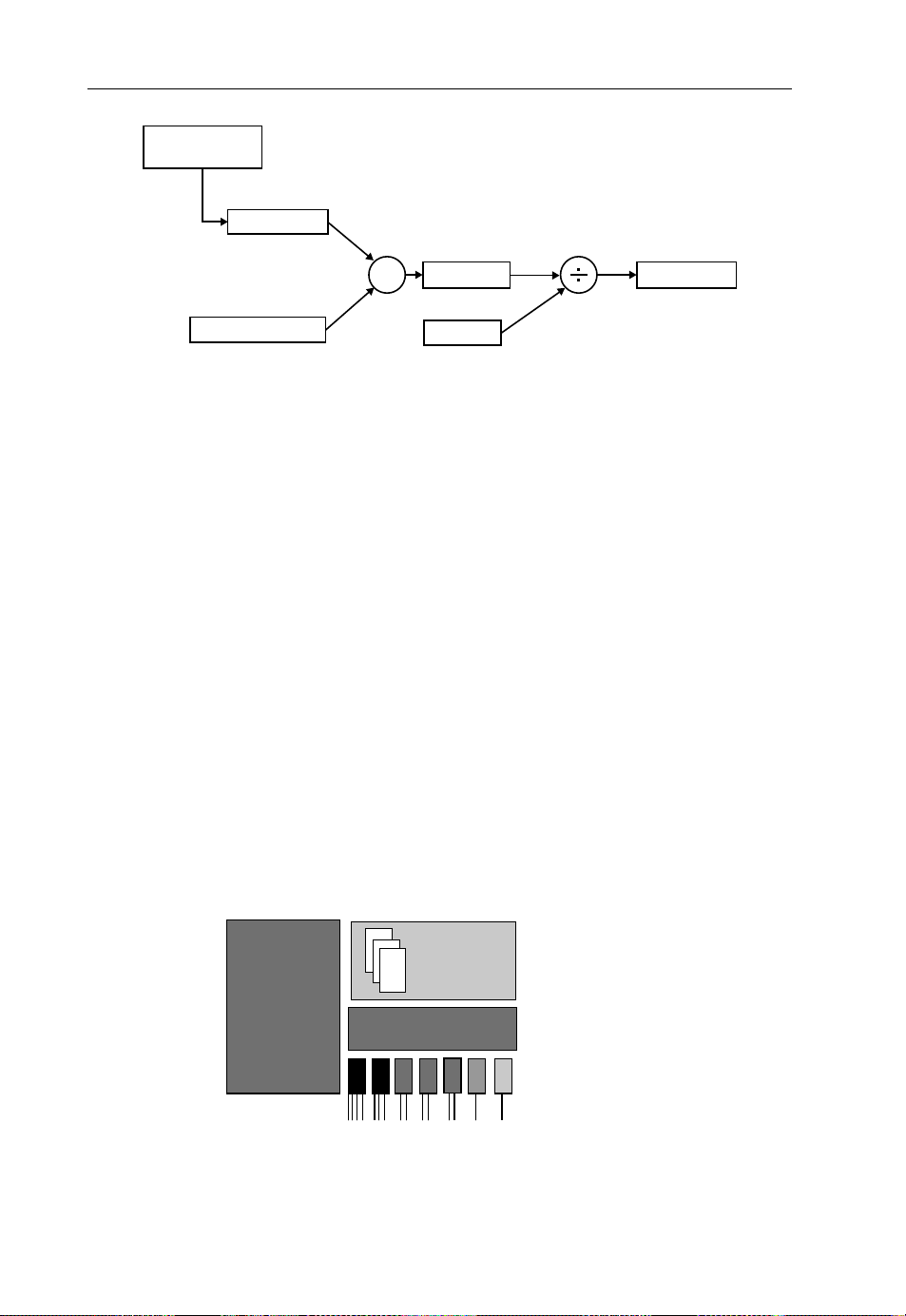
40 The Emerging Core and Metropolitan Networks
traffic related to
service “X”
dimensioning
elements’ price list
X
investment
useful life
amortization
Figure 1.7 Process to evaluate the investment and amortization of a telecommunication network
As for the equipment deployment, the starting point naturally consists of dimensioning the
requirements as a resu lt of traffic estimation (Figure 1.7).
Amortization is the process of allocating one lump sum (CAPEX) to different time periods.
Amortization can be calculated by different methods, but its concept describes the total
expenses due to an asset over the time of its economic usefulness. As a coarse rule, the
following list can be used to estimate the useful lifetime:
.
network infrastructures (excavation, buildings, ...) 30 years
.
optical fibers and copper wires 10 years
.
network equipment 5 years
.
software 3 years.
Different systems and technologies give rise to different components and, thus, different
CAPEX analyses.
Figure 1.8 represents a general block model for most switching systems, including interface
components, software, power supply, and common hardware elements. The cost mode l
obviously arises from adding all individual prices for each component.
Sometimes, network operators prefer to establish a certain redundancy for some (common
hardware) components so as to ensure service reliability.
Software
Software
(libraries)
Power
Power
supply
supply
Hardware: Switches,
Hardware: Switchs,
Rx, Tx, etc.
Rx, Tx, etc.
(libraries)
Interfacing cards
for clients
Figure 1.8 Simplified block model for a switching system
Page 53

Transport Networks Economics 41
XC
XC
XC
XC
Conmutador
Conmutador
DWDM
DWDM
DWDM
DWDM
nλ nλ
Electrical
Conmutador
Conmutador
Eléctrico
Eléctrico
Matrix
Eléctrico
Eléctrico
OXC
OXC
OXC
OXC
Conmutador
Conmutador
Optical
Conmutador
Conmutador
Matrix
Optico
Optico
Optico
Optico
DWDM
DWDM
DWDM
DWDM
λ1... λn
Figure 1.9 Hybrid SDH/lambda switching node
On the other hand, manufacturers also may introduce hybrid system s taking into account that
common elements may be used by different technological solutions to accomplish a given
function (switching packets, for instance).
Figure 1.9 shows the case for a transparent and opaque hybrid solution for a node where some
lambdas are switched at the optical level, requiring no electrical regeneration (most lambdas
are bypassed and transponders are only used to insert/extract lambda on/off the transmission
line), whereas opaque switching (for low-granularity lines and to deal with the ingress/egress
lambda of the transparent module) require electro-optical conversion. In fact, modular
equipment is offered in a “pay as you grow” model to keep upgrading systems according
to traffic growth for different (and interoperable) capacities like opaque/transparent hybrid
nodes or L2/L3 multilevel solutions.
Aside from the amortization time schedule, network operators plan network infrastructures
several years in advance. That is the reason why the introduction of new technologies must
consider not only current prices, but also somewhat different ones for the future, taking into
account certain conditions.
.
Vendors offer discounts to network operators; discounts are very frequent because this is a
way for vendors position their products as the de facto standard by massive installations.
.
Equipment prices get lower after standardization agreements.
.
Learning curves finally represent a significant price reduction as technologies mature. The
empirical rule that states “as the total production of a given equipment doubles, the unit cost
decreases in a constant percentage” can be combined with an initial estimate of market
penetration to allow for predicting such a price reduction due to the maturity process.
These kinds of techno-economical prediction are usually carried out in combination with
more general strategic considerations: whether network operators expect to expand their
business outside present geographical limits or not, whether they will be able to reuse
equipment for other purposes or places (from core networks to metropolitan ones, for
example), or simply if it is possible to buy equipment from other companies, and so on.
On the other hand, cost models are always performed with a sensitivity analysis that
highlights which elements are the most important to define a trend in the price evolution of
Page 54

42 The Emerging Core and Metropolitan Networks
a system and, as a consequence, to provide a tool for benchmarking it. This task must be done
in combination with a general vision of the network architecture, since it is not straightforward
to compare different topologies and multilevel interoperation.
1.5.2 Operational Expenditure Models
OPEX is not directly part of the infrastructure and, thus, is not subject to depreciation; it
represents the cost of keeping the network infrastructure operational and includes costs for
technical and commercial operations, administration, and so on. Personnel wages form an
important part of the OPEX, in addition to rent infrastructure, its maintenance, interconnection
(with other network operators’ facilities) cost s, power consumption, and so on.
Only considering specific OPEX derived from network services provision, the following list
can be used as a guide to analyze its components:
.
Costs to maintain the network in a failure-free situation. This includes current exploitation
expenditures, like paying rents for infrastructures, power for cooling and systems operations,
and so on.
.
Operational costs to keep track of alarms and to prevent failures. This involves the main
control activities to ensure QoS, namely surveying systems and their performance versus
traffic behavior.
.
Costs derived from failures, including not only their repair, but also economic penalties (in
case an SLA states them for service failures).
.
Costs for authentication, authorization, and accounting (AAA) and general management of
the network.
.
Planning, optimization, and continuous network upgrading, including software updating and
QoS improvement.
.
Commercial activities to enhance network usage, including new service offers.
Several approaches to analyzing OPEX can be used. To compare technologies and network
architectures or different services implementations, a differential approach may be sufficient
instead of considering all OPEX parts. However, if a business case-study requires knowledge of
all costs and revenues, then a total OPEX calculation must be performed.
On the other hand, OPEX calculation is different for green-field and migration situations;
for instance, bulk migration of customers or removal of old equipment will not be taken into
account for a green-field scenario. Furthermore, bottom-up or top-down approaches can be
used to calculate OPEX: the top-down method fits well to get a rough estimation of costs, as a
starting point for a finer analysis of relative costs; the bottom-up approach is based on a detailed
knowledge of operational processes.
Various approaches can be combined when dealing with OPEX calculations. In addition,
OPEX and CAPEX may be balanced for accounting exploitation costs (e.g., buying or renting
infrastructures) and some OPEX concepts can also be included in different items: salaries, for
instance, can be considered as an independent subject or inside maintenance, commercial
activities, and so on. A deep evaluation of OPEX is really important; in fact, it is possible that
some technologies may offer high performances and perhaps at rel ative low CAPEX, but their
Page 55

Transport Networks Economics 43
maintenance
reparation
charging billing/ marketing
netw. spec. infrastr. cost
network planning
provisioning and service mgmt
availability
number of users
average link length
network dimensions
number of boxes
network techonology
number of connections
Figure 1.10 Network characteristics as cost drivers for OPEX calculations
complexity, software updating, power consumption, or personnel specialization may render
them unaffordable.
Figure 1.10 shows, in arbitrary units, the dependence between OPEX components and
network characteristics, considered as cost drivers so as to appreciate the impact of network
technology on operational expenditure. It is clearly observed that network technologies
determine the cost for maintenance, reparation, provisioning, service management, and
network planning. They have less impact on charging/billing and commercial activities.
A more detailed analysis of Figure 1.10 gives the following information:
.
The numb er of network elements (network components – e.g., routers, OXCs, PXCs) has
an important impact on the cost for maintenance/reparation.
.
Network technology determines not only network performance, but also some specific cost
of infrastructure (more or less floor space and need of energy).
.
Network dimension is important for all considered OPEX subparts, except AAA (run in
centralized scheme) and marketing.
.
The number of connections strongly influences the cost for provisioning and service
operation and management (each connection needs to be set up), but it is less important
for network plan ning.
Page 56

44 The Emerging Core and Metropolitan Networks
.
The number of users determines the cost for provisioning, network planning, charging/
billing, and marketing, but has a small impact on the cost of maintenance and reparation.
.
The average link length has little impact on maintenance, but may be significant for
reparation cost when failures require a technician to go on site.
1.5.3 New Business Opportunities
1.5.3.1 The Business Template
Techno-economic drivers must let business progress, since network services are no longer of
public strategic interest, covered by national monopolies. Such a situation is not new, but it is
still evolving in accordance with clients’ demands and technical improvements. Just to
complete the vision and help in understanding telecommunication network evolution, some
ideas about market agents and their driving actions are presented here.
The technological evolution of network infrastructure leads it to becoming multifunctional.
Hence, the old scheme of one network for one purpose and kind of client, in a vertical structure
(see Figure 1.11), must be changed into a matrix scheme of services based on a unique transport
infrastructure: all tasks related to network service provisioning are no longer repeated for every
telecommunication business; for instance, AAA is common for IPTV, teleconferencing, or
POTS, as well as QoS assurance systems, network configuration, or customer commercial
issues. This scheme of cross-management can also lead to telecommunication companies
exploding into several specialized companies that cover a part of the business (for more than
one single network operator, perhaps). In addition, the market agents involved in the
telecommunication business, from content providers to end custom ers, play their role freely
in a cross-relational model (see Figure 1.12), where commercial interests should prevail.
So, companies have to redesign their business model along the guidelines discussed so far:
a method of doing business by which telecom companies generate revenues, in order to set
strategies and assess business opportunities, create or get profit of synergies and so align
business operations not only for financial benefits, but also to build a strong position in the
Figure 1.11 Network operator business model scheme adapted to NGN concept, from a pyramid
structure to a matrix one
Page 57

Transport Networks Economics 45
C ontent provi der
C ontent provi der
C ontent provi der
Content provider
C ontent provider
C ontent provider
Content provider
Service
Service
Service
Service
provider
provider
provider
provider
(VASP)
(VASP)
(VASP)
(VASP)
Network
Network
Network
Network
Service
Service
Service
Service
provider
provider
provider
provider
Service
Service
Service
Service
provider
pr ovider
pr ovider
pr ovider
(VASP)
(VASP)
(VASP)
(VASP)
End users
C ontent provi der
C ontent provi derC ontent provider
C ontent provi der
Content provider
Network
Network
Network
Network
Service
Service
Service
Service
provider
provider
provider
provider
Service
Service
Service
Service
provider
pr ovider
pr ovider
pr ovider
(VASP)
(VASP)
(VASP)
(VASP)
Figure 1.12 Telecommunication market agents and their cross-relationship just governed by commercial interests
market. In fact, network technology and market environment evolution affect all components
of a business model, namely market segment, value proposition, value chain, revenue
generation, and competitive environment. For these reasons, new business opportunities arise
and the business model template has to be updated.
For the market segment, defined as the target customers group, it is clear that incumbent
network operators may find virtual network operators as new clients and so the market
liberalization generates new market segmentation. Each segment has different needs and
expectations (e.g., business customers, banking) and companies create services for a specific
types of customer;
3
in addition to customer types, geographical issues must also be considered
for market segmentation.
The segmentation of the market, in turn, can be based on various factors, depending on the
analysis to be performed; for example, different parts of a network can be shared by different
market segments; every market segment will have its own behavior, reflected in its demand
4
model.
Conversely, the way of using applications/services depends on the type of market
segment to which they are focused (the same applications have different characteristics in
residential and business areas, for example). Therefore, a proper market segmentation analysis
should not only aim to map traffic demands onto transport services, but also tackle the heart
of the network operator’s business model: the question of how a network operator is designing
3
Some broadband services target roughly the same segments, such as big enterprises (for instance, VPN services,
virtual network operators, or regional licensed operators) and Internet service providers. But residential, business and
public administration market segments are normally offered network services that specifically support applications for
storage, grid computing, multimedia content distribution, and so on.
4
This aspect includes the applications and the way they are used by those customers: frequency, time-of-the-day
distribution, holding time, and so on.
Page 58

46 The Emerging Core and Metropolitan Networks
Web interface
UNI
User Network
Business Plane/
Service Plane
Management Plane
Business and
Business and
management plane
management plane
interworking
Management
Management
and control plane
and control plane
interworking
Control Plane
Data Plane
Figure 1.13 Interfaces user-network provider that may generate value proposition to different market
segments
its access segment, which kind of alliance should be formed between network operators and
content providers or virtual access services platform (VASP) taking into account traffic models
derived from new customer demands like IPTV or new customer approaches to telec ommunication issues like Web2.0. Finally, as far as network operators contract SLAs with their clients
(availability and QoS), their profit depends on sharing their network infrastructure optimally.
The importance of properly segmenting the target market is critical in the development of
a value proposition. The value proposition is identified by the combination of the customer
needs, the services required to fulfill their needs, and the virtual value of the product.
5
NGNs
allow network operators to design new products/services that can have value to some
customers, like those derived from VPNs and temporary bandwidth leasing (BoD). In addition,
customers are going to be able to access network services using new service interfaces and
procedures. These interfaces can be provided on different planes (or any combination of them):
.
Service plane. VASP may offer their products with (or without) a middleware to their
customers using this interface to access network resources, either via previous reservation or
in a dial-in mode (with a certain service availability).
.
Management plane. This is the old way. Carriers establish SLAs and reserve network
resources either for dedicated connections or by statistical knowledge of traffic. Internally,
management/control plane interworking functions get the transport system (data plane) and
set the required connections.
.
Control plane. Network operators let some users directly enter into their network cont rol
system through the UNI. In this way (as established in an SLA), those customers can set up,
modify, and tear down their own VPN once the required AAA process has been performed
(by the management plane).
Thus, network operators’ migration activities should take into account that deployment of
new services and functionalities may attract new users and increase the operator position in the
market. Such an approach is worth it even if the net cash balance remains unaffected due to
extra costs for implementing the new services.
5
The real value of the product is formed once customers select the service among available alternatives, according to its
functionality and price.
Page 59

Transport Networks Economics 47
Figure 1.14 Market agents’ roles mapped to the value chain by network layersto show service interfaces
On the other hand, virtual network operators (VNOs) may find easier ways of creating
specialized services (TV distribution, for instance) without any handicap derived from the
necessity of maintaining old services, QoS systems, or complex AAA mechanisms: their value
proposition is clearly identified by a market segment. This is just the opposite case of
incumbent telecommunication companies, composed of a number of departments that offer
differently valued proposition services; then, synergies, market position, and customer fidelity
are their main assets.
The creation of new services also modifies the value chain that represents a virtual
description of the environment in which the market agents offer their services. If market
desegregation implies unbundling the value chain to exploit a set of cross-relationships
(Figure 1.14); also, tradeoffs and vertical alliances can be formed. These alliances are
interesting whenever they produce added value to end customers because of technical
improvement or service enhancement (Figure 1.14).
In fact, each box of the value chain represents an activity (Figure 1.15), and groups of
activities are generally covered by inde pendent market agents.
6
This value chain scheme
illustrates the connections between the telecom network layers and the corresponding telecom
services; layer handovers can be commercial transactions between different organizations or
enterprises, or they can be internal (technical) interfaces without any real commercial
transaction. For example, there may be fiber availability issues (with underlying ducts and
rights of way); the access to this dark fiber is then a service (something to sell), and the seller is
known as a “dark fiber provider.” The organization that is purchasing this service – the buyerhas also to place the necessary equipment infrastructure (WDM, SDH) in order to become a
Network Operator.
7
Other buyer–seller market profiles can be identified through the value
chain in similar ways.
6
Here is a key to the identification of some roles: customer, packager, connectivity provider, access network provider,
loop provider, network service provider, application service provider, and content provider.
7
The light boxes denote the seller and the dark boxes the buyer of the service at that interface.
Page 60

48 The Emerging Core and Metropolitan Networks
Figure 1.15 Impact of migration factors to business model components
In addition, the initial roles of the market agents can evolve according to commercial
interests; for example, equipment vendors can develop network management activities, since
their knowledge of the systems (hardware and software) allow them easily to propose valueadded functions; in the same way, big media companies (content providers) may become
service providers or, conversely, VASP may get exclusive rights on certain contents. Network
operators can split old functionalities and even outsource some of them in order to concentrate
their operations in either connectivity services (“bit transmission”) or services of higher quality
closer to the end customer (with higher margins); on the other hand, the FMC can have different
consequences in the role that network operators would like to assume in the future.
The role of network operators within the value chain scheme given in Figure 1.15 is going to
comprise other activities, within the value chain, apart from selling pure network services; for
instance:
.
Purchasing multimedia contents and distributing them throughout a nationwide platform
for other (VASP) agents to deal with them.
.
Leasing or buying underlying network infrastructure (right of way, network equipment,
fiber) from utility companies or other vendors and renting part of it to other network operators
as their network migration is carried on.
.
Renting or selling buildings and complementary equipment (for cooling, for example) when
they are no longer needed by new switching and transmission systems.
.
Service provisioning to other VNOs.
The revenue amount is the main assessment to determine the network operator’s ability to
translate the value of the product into the money received. A typical revenue model is based on
monthly subscription fees and costs of transactions, commissions, and services used by
customers. A supplementary income can be achieved by selling or leasing a product/service
to other, nonresidential companies. In each situation a network operator should consider an
appropriate pricing model in order to maximize the revenue.
Page 61

Transport Networks Economics 49
Moreover, the network migration strategy will be planned by a network operator, as long as
this is possible, choosing the smallest cost of investment that may lead to greater profitability.
Providing new services, after an initial investment, is a risk for several years to create new
revenue-generation streams. Thus, increasing these margins is always an objective for any
market agent before extending its role in the value chain or capturing new market. From the
network operator point of view, it is always crucial to monitor the margins, since these are
constantly change, and to plan network migration and to update the business plan, accordingly.
This is not a straightforward operation; some puzzling considerations are described below:
.
New services typically mean more profits from higher income; however, the higher the
number ofservices, the more complex the management of them, aside from the effort required
to search newcustomers. Then, the higher the diversificationof services for value proposition
and market segment capture, the bigger the problem with accounting and operating.
.
Higher network quality and closer matching between customers’ demands and network
capabilities mean potentially more subscribed services and higher income. More subscribers,
attracted by emerging, pioneer services lead to increasing income, provided that transport,
control, and management do not overload network capabilities.
.
In general, however, a higher number of customers means a faster return of investment, thus
allowing reduc tions in the prices for services; and customizing existing services allows
proposing more services and making them used more frequently, thus generating higher
incomes.
.
In addition, higher accessibility to the network services (through geographical expansion,
higher availability derived from FMC or via interconnection facilities) and higher penetration due to combined service proposals increase the number of new subscribers and help to
keep their fidelity.
.
On the other hand, technical modifications affecting the traffic model will have consequences
on the revenue streams. For example, the volume of metropolitan network traffic will be
affected by the growth of social networks; network operators and VASP should then study
carefully how IP networks are going to work in coordination with L1 and L2 transport layers
and also analyze the importance of developing multicast-capable transmission systems,
as well as the placement of service nodes in order to avoid bottlenecks. However, sometimes
it can be proven that an extra initial investment (CAPEX) will be compensated by a
consequent OPEX reduction: introduction of GMPLS for broadband standard networks
will surely compensate the extra provision of bandwidth for some services unless network
operators are obliged to share their transport capacity or extend it for the rest of their networks
by the regulatory authority.
.
Incumbent network operators must finally face the challenge of designing their network
migration, not only to reach more revenue generation and gain market position, but also to
keep backward compatibility. This decreases the risk of the investment and allows one to
perform the infrastructu re modernization in reasonable time schedules with the interesting
possibility of reusing equipment.
In general, a higher value of the network and a higher position on the market allows financial
advantages and new revenue streams for the telecommunication core business, like leasing offices
and selling auxiliary equipment, since the eventually selected winning technology has lower
requirements in terms of cooling, footprint and smaller real estate for the housing of the equipment.
Page 62

50 The Emerging Core and Metropolitan Networks
Figure 1.15 summarizes the possible impact of the already analysed components on network
migration factors and to NO’s business model. Perhaps all factors involved in a migration
strategy will have some influence on the company competitiveness, and so a migration strategy
is always designed having as a goal to increase revenues and/or to gain a better position in the
competitive environment. In the latter case, a network operator can deploy new serv ices and
functionalities to develop niche markets, thus attracting new customers, and achieve diversification of services so as to extend their market segment, attracting customers that prefer dealing
with a unique network operator and get advantages of synergies for both network services and
AAA tasks. The impact of regulatory framework on the migration strategies has, amongst other
things, the following consequences from a NO point of view:
.
Changes in the regulatory framework taken from the governments may either accelerate or
discourage new entrant NOs, FMC or inter company (vertical) alliances.
.
Vertical or horizontal alliances, even if they do not end up in one company’s takeover,modify
the competition environment (for suppliers and clients, respectively). On the other hand, the
advancement in standardization, in contrast to exclusive vertical (in the value chain)
dependencies, also modifies the competitive environment of network operators and other
telecommunication market agents.
Network operator clients are also taking advantage of new network service implementations
for end-to-end broadband communication, to be based on the NGN concept; thus, the
competitive environment is becoming harder, as network operators’ customers can trade off
different network operator service propos als and use UNI to different transport infrastructures,
so as to build up their own customized VPN (see Figure 1.16) or lease part of their bandwidth
capacity, thus acting as VNOs.
1.5.3.2 Business Opportunities
VPN services, regardless to the association with FMC issues, seams to be the most important
driver in telecommunication business plans in the short term. Currently, VPNs are mainly
supporting legacy data services in circuit switched (CS) networks. However, the advances in
Figure 1.16 (a) Tradeoff network services from different network operators. (b) VPN concatenation to
get extended services under a unified management. (CE: customer edge.)
Page 63

Transport Networks Economics 51
Figure 1.17 VPN cascade either to get dynamic network resources allocation or to be permanently used
by VNOs (CE: customer edge; PE: provider edge; P: provider)
network technologies for VPNs are making it possible for NOs to operate a packet switched
(PS) transport infrastructure like a CS one. But there is more than simulating CS networks over
PS networks with the economical interest derived from statistical multiplexing and resource
sharing. The currently perceived image of a “dummy” IP network will be reconsidered with the
advances made possible in VPN technology: a NO may take advantage of the VPN technology
to provision restricted connectivity using diffserv
8
-instead of over-provisioning network
capacity- offering, thus, differentiated SLAs. Hence, ISPs and other VASPs could implement
their preferred mechanisms to ensure application quality (for information integrity and the
speed at which it reaches their customers).
AVPN may simply be used to implement VNO network resources (Figure 1.17). This fact,
and the possibility of part-time network resource renting as BoD for any network operator
client, is produc ing a radical change in the telecommunication business.
Moreover, incumbent network operators can evidently profit from operating their transport
resources by means of a new developed TE approach. This policy can be based on the VPN
technology,together with a network operator’s ability to manage their capabilities and Ethernet
network resources by reusing network elements (for the “virtuality” of the VPN paradigm) and
make more scalable the management of the whole infrastructure by (virtually) dividing it and
operating it as usual with the old pyramid scheme (Figure 1.17).
The expectations opened by new technologies and the market environment go beyond
VPN-related topics. Improvements in network exploitation and new network service availability also give network operators new opportunities derived from:
.
Cheaper and faster network upgrade (according to traffic demand) allowed by NGN.
Furthermore, an NGN control plane makes it possible to adapt network resources quickly
to client demands (a few minutes instead of days to reconfigure transport resources).
8
For packet-switched networks, diffserv concepts of QoS can easily be understood as a mechanism of setting
transmission preferences (at edge or core nodes) for determined sorts of packets (over a simple best-effort approach):
those of a specific kind of application (real-time class, for instance) or those of a privileged customer, VPN, and so on.
The concept is not new, and examples of its implementation may be found in standards of ATM services or RPR
architecture. For IP networks, this non-neutral network operator performance, beyond a plain flux control, is a hot issue
actively opposed by ISPs that promote ruling a net neutrality.
Page 64

52 The Emerging Core and Metropolitan Networks
.
Reduction of time needed to provide connections and new services.
.
Multicast traffic carried over p2mp connection solutions, implemented in new switching
equipment, allow the introduction of specific architectures for triple-play services (namely
IPTV or other multim edia applications).
.
Developing Ethernet solutions for extended networks allows carriers to reduce CAPEX for
wide area networks and specific-purpose networks.
.
Migration from ring to mesh topologies happens to allow more efficient resilient strategies
for packet-switching networks: one can think of restoration versus protection, for
example.
.
Complete transparent optical networks (instead of hybrid solutions) for OSI level 1 are also
expected to reduce CAPEX by eliminating undue O/E/O conversions. The possibility of
directly managing wavelengths also has some OPEX advantages (wavelength-switchedoriented networks).
.
Parallel development of the service layer, over the control plane, is often addressed to
Ethernet, new applications like storage area networks, video on demand, grid computing,
and so on.
Aside from these improvements in network exploitation and in the new services arising from
NGN architecture and deployment of new technologies, some collateral new business must be
mentioned too, since their economical impact is not negligible.
VoIP and migration to the IPv6 protocol are making possible a complete quadruple-play
offer, as well as easier ways of managing networks to provide any kind of networ k service,
including those for real-time applications, by means of the same packet-switched-oriented
equipment.
As new equipment is smaller and need less cooling and DC generators, a considerable
amount of real estate is made redundant in central offices, thus allowing NOs to get extra
revenues from their selling or renting. This new real estate business opportunity should be
perceived as in an integral part of the current trend in extending the role of NO’s towards a value
added service provider which will eventually turn them to their current antithetical pole i.e. the
VASP could become a (V)NO offering specialized network services. Finally, the aforementioned SLA diversification supporting dynamic network service opportunities, as well as a
complex trade off between the factors affecting it, may spawn the appearance of a new market
agent; that of the extended service broker. This is an agent serving as the “middle-man”
between suppliers and customers, operating not only in a direct NO-client scheme but also
under a dynamic and multi-step (VPN cascade, for instance) network service leasing pattern.
Acronyms
AAA authorization, authentication, and accounting
ASON automatic switched optical network
ATM asynchronous transfer mode
BER bit error rate
BoD bandwidth on demand
CAPEX capital expenditure
E-NNI external NNI
Page 65

Acronyms 53
FMC fixed–mobile convergence
GMPLS generalized multi-protocol label switching
IETF Internet Engineering Task Force
I-NNI internal NNI
IPTV Internet protocol television
ITU International Telecommunications Union
LSC lambda switching capability
LSR label-switched router
MAN metropolitan area network
MEF Metro Ethernet Forum
NGN next-generation networks
NNI network-to-network interface (see ASON)
OCS optical circuit switching
O/E/O optical/electrical/optical
OIF Optical Internetworking Forum
OPEX Operational Expenditures
OSI open systems interconnection
OSS operation service support
OTH optical transport hierarchy
OTN optical transport network
OXC optical cros s-connect
p2mp point-to-multipoint
PBB provider backbone bridge
PBB-TE provider backbone bridge traffic engineering
PLR packet loss rate
PoP point-of-presence
PoS packet over SONET
POTS plain old telephone service
PSC packet-switching capability
PXC Photonic Cross-connect
QoS quality of service
RPR resilient packet rings (refer to IEEE 802.17)
RSPV-TE reservation protocol with TE
SDH synchronous digital hierarchy (refer to the ITU-T framework)
SLA service level agreement
SONET synchronous optical network (refer to the ANSI framework)
TDM time-division multiplexing (see SONET and SDH)
UMTS Universal Mobile Telecommunication System
UNI user-to-network interface (see ASON)
VASP virtual access services platform
VNO virtual network operator
VoIP voice over IP
VPN virtual private network
WDM wavelength-division multiplexing
WSON wavelength-switched optical network
Page 66

54 The Emerging Core and Metropolitan Networks
References
[1] Spargins, J.D., Hammond, J., and Pawlikowski, K. (1991) Telecommunications: Protocols and Design, Addison-
Wesley.
[2] Dorf, R.C. (ed.) (1997) Electrical Engineering Handbook, 2nd edn, CRC Press.
[3] MEF 10.1 Technical specifications (November 2006) Ethernet services attributes Phase 2.
[4] IETF RFC 2702 (09/1999) Requirements for traffic engineering over MPLS.
[5] Davie, B. and Rekhter, Y. (2000) MPLS Technology and Applications, Morgan Kaufmann Phublishers.
[6] ITU-T Recommendation Y.1311 (03/2002) Network-based VPNs – generic architecture and service requirements.
[7] IETF RFC4026 (03/2005) Provider provisioned virtual private network (VPN) terminology.
[8] ITU-T Recommendation Y.1312 (09/2003) Layer 1 virtual private network generic requirements and architecture
elements.
[9] ITU-T Recommendation Y.1313 (07/2004), Layer 1 virtual private network service and network architectures.
[10] Tomsu, P. and Wieser, G. (2002) MPLS-based VPNs, Prentice Hall.
[11] ITU-T Recommendation G.709 (03/2003) Interfaces for optical transport network (OTN).
[12] Comer, D.E. (2003) Internetworking with TCP/IP Principles, Protocols and Architectures, Prentice Hall.
[13] ITU-T Recommendations G.8080/Y.1304 (November 2001) Architecture for the automatically switched optical
network (ASON).
[14] IEEE 802.1Qay (2007) Standard provider backbone bridge traffic engineering.
[15] Serrat, J. and Galis, A. (2003) IP Over WDM Networks, Artech house.
[16] Kadambi, J. Crayford, I., and Kalkunte, M. (2003) Gigabit Ethernet Migrating to High Bandwidth LANs, Prentice
Hall.
[17] IETF RCF 5212 (07/2008) Requirements for GMPLS-Based Multi-Region and Multi-Layer Networks
(MRN/MLN).
Page 67

2
The Advances in Control and Management for Transport Networks
Dominique Verchere and Bela Berde
2.1 Drivers Towards More Uniform Managem ent and Control Networks
We observe the convergence at different levelson the network given the application and service
convergence as presented in Chapter 1 (and might be highlighted /summarized here); the
convergence and the related Internet protocol “(IP)-orientation” in network services seems
inevitable.
What is the network convergence? The converged IP-based service platform, despite the
wide variety of network technologies, requires network control and management functions that
tend to be uniform at the different switching layers in order to reduce operational expenditure
(OPEX). The tran sition from “a network per a service” to “network integration of multiservices and multilayer with support for end-to-end quality of service (QoS)” concept enables
one to get higher network resource utilization coupled with higher resiliency.
This section further elaborates the new role of the network control functions and network
management functions relying on this integration at different transport layers by considering
the network layer (i.e., IP layer or layer 3) with the convergence to IP-based services using the
essentials of traffic engineering (TE) and QoS support, and how these requirements can be
illustrated in IP or IP/multi-protocol label switching (MPLS) networks. Then we consider the
data layer (i.e., layer 2) as essentially based on Ethernet with the transport MPLS (T-MPLS)
1
1
At the time this text was produced, key agreements have been defined between ITU-T SG15 and IETF leadership
concerning T-MPLS/MPLS-TP evolution in December 2008. The agreements can be summarized in three statements:
(i) there is no agreement, or proposal to cancel or deprecate the T-MPLS recommendations from ITU-T currently in
force; (ii) ITU-Twill not undertake any further work to progress T-MPLS;and (iii) it is possible that the ITU-T will have
a future role in MPLS-TP standardization.
Core and Metro Networks Edited by Alexandros Stavdas
Ó 2010 John Wiley & Sons, Ltd
Page 68

56 The Advances in Control and Management for Transport Networks
extensions, resilient packet ring empowered with TE and operation, administration, and
maintenance functions. Finally, we consider the physical layer (i.e., layer 1) as essentially
based on optical transmission networks with synchronous optical network (SONET)/synchronous digital hierarchy (SDH) and its next-generation SONET/SDH enhanced with data
protocols such as generic framing procedures, virtual concatenation and link capacity
adjustment schemes, G.709, and optical transmission technologies [33].
In circuit-switched layer transport networks, a layer (L1) path is constructed with physical
links and ports, one or many optical wavelengths, or time-division multiplexing (TDM)
timeslots, and an L1 path is established and dedicated to a single connection between the access
points (APs) of the transport network for the duration of the applications using the connections.
In packet-switched networks, packets are forwarded hop by hop at each network element
involved in the connection (e.g., IP routers or Ethernet switches) based on information in the
packet header. An IP-switching-based network provides connectivity services while making
efficient use of network resources by sharing them with many connections. It is based on the
assumption that not all the provisioned connections need to use the resource all of the time.
Packet-switched networks (PSNs) can be connectionless or connection oriented. PSNs can be
based on the IP, such as IP networks (connectionless) or IP/MPLS networks (connection
oriented), or can be based on the Ethernet protocol, such as Ethernet network (connectionless)
or Ethernet/MPLS transport profile (MPLS-TP) networks (connection oriented). IP-based
networks are said to be layer 3 and Ethernet-based networks are said to be layer 2 in reference
to the Open Systems Interconnection (OSI) basic reference model [31].
In connectionless packet-switched networks, once the data packet is sent on the interface,
the connection is available until further information is either sent or received at this same
interface.
In connection-oriented PSNs, connections are established and maintained until connectivity
is no longer required, regardless of whether data packet has been transmitted or not.
Network services are classified according to three assigned groups taking into account their
switching capabilities, features, relations, and differences. The three groups identified are
virtual private networks (VPNs) on transport layer 3, VPNs on transport layer 2, and VPNs on
transport layer 1. Additional network services subclassification can be defined for the layer 3,
such as public IP and business IP, extending the network service classification to five groups.
The characteristics of each network service are usually described along with their performance
parameters.
The different layers’ VPNs are explained from the perspective of connectivity, control,
scalability, and flexibility. Mechanisms enabling the network “confidentiality” are described,
such as MPLS and tunneling in PSNs, and wavelength services enabled by L1-VPN services
from optical networks. How network services should match the connectivity requirements
of distributed applications is not developed in this chapter, but the connectivity requirements of
on-demand storage, (grid) cloud computing, or multimedia-based distributed applications
are developed in [32].
Three classes of network services are identified based on the related switching and
transmission layers in which they are provided to the network customers edges (Table 2.1):
1. Layer 1 network services provide “physical layer” services between the network client
and 5the provider network (server). The customer edge (CE) equipment belongs to the same
L1-VPN as the other equipment of the provider network (provider edge (PE) nodes,
Page 69

Drivers Towards More Uniform Management and Control Networks 57
Table 2.1 Network service modes versus switching layers
Network service mode Switch capability layer
Layer 1 Layer 2 Layer 3
Connectionless
packet-switched
Connection-oriented
packet-switched
Circuit oriented OTUx, (OTN)
Optical packet
switching
STM-n (SDH),
STS-n (SONET)
Ethernet IP
Ethernet/MPLS-TP, ATM,
frame relay
IP/MPLS
provider (P) nodes). The connections can be established based on TDM timeslots (SONET/
SDH), optical wavelengths, optical wavebands, or physical ports, such as Ethernet ports or
fiber ports.
2. Layer 2 network services provide “data link layer” connection services to the CE equipment
involved in the L2-VPN. At the interface, the forwarding of user data frame s is based
on the control information carried in the data link layer headers, such as media access
control (MAC) addresses (for Ethernet), virtual circuit identifier/virtual path identifier
(for asynchronous transfer mode (ATM)) or data link connection identifier (frame relay).
The customer layer 2 data frames are associated with the right L2-VPN by each PE node.
3. Layer 3 network services provide “network layer” services between the CE equipment
involved in the L3-VPN. At each user-to-network interface (UNI), the forwarding of data
packets is based on the IP address information embedded in the layer 3 header; for example,
IPv4 or IPv6 destination address.
The network services have been generically labeled VPN at L1, L2, and L3. For each of these
three types of network service, typical performances are defined and usually referenced by
network operators to alloca te the connectivity service requests.
The layer 3 network service (such as IP) is, as already mentioned, divided into public and
business IPs, where public IP is a “best-effort” service and business IP is a higher priority class
of services that, for example, can handle latency-sensitive applications. “Business IP” is also
presumed to guarantee higher bandwidth from CE to CE.
The VPN services on all layers, L1, L2, and L3, are divided into either a permanently
configured network service (typically provisioned by a network management system (NMS))
or an on-demand service (typically triggered and signaled from a network controller)
(Table 2.2). The permanent service is totally managed by the network operators, but the
on-demand connectivity service can be triggered dynamically by the CE node through a
suitable UNI.
L1 and L2 VPN services are further divided according to their availability; this can be high or
low availability. The high-availability network services are normally configured with defined
protection/restoration schemes [2], which offer an alternative way for carrying the traffic
impacted by network failures. Different types of distributed application are identified and
reported in [32], and for each case the application performance requirements are checked
against the network services.
Page 70

58 The Advances in Control and Management for Transport Networks
Table 2.2 Mapping applications into network services (light: application will run on this network
service; dark: more efficient implementation, white: no support for the application)
Public IP
Bu sin e ss IP
VPN - L3
VPN - L2
VPN - L1
perm anen t
on-demand
perm anen t, H i avail
perm anen t, L o w avail
on-demand, Hi avail
on-dem an d , Low avai l
perm anen t, H i avail
perm anen t, L o w avail
on-demand, Hi avail
on-dem an d , Low avai l
- Back-Up/ Restore
Storage
- Storage on Demand
- Asyncrhonous Mirroring
- Synchronous Mirroring
Gridcomputing
- UtilityGrid
- Compute Grid
- Data Grid
- VideoBroadcast(IP-TV)
Multimedia
- Video on Demand
- Video Download
- VideoChat
- NarrowbandVoice,data(VoIP,...)
- Digitaldistribution,digitalcinema
- Gambling
- Gaming
- Video conference
Tele-medicine/diagnostic
It should be noted that the same transport layers could be used to provide multiple VPN
services. For example, a transport layer based on SDH can be used to provide layer 1 (e.g.,
TDM), layer 2 (e.g., Ethernet), and layer 3 (e.g., IP) VPN services. For this reason, it is
important to distinguish VPN clients and VPN transport networks (server part). Both VPN
transport and VPN client each have their own set of connectivity inputs and outputs known as
APs.
When the VPN client switching capability layer and VPN transport switching capability
layer are different, the VPN client layer information must be adapted for transmission across
the transport VPN. Examples of adaptation functions include multiplexing, coding, rate
changing, and aligning (which may also include some form of fragmentation and sequencing
if the transport layer traffic unit is smaller than the service layer traffic unit). Even if VPN
transport layer trail/connectionless trail terminat ion functions are VPN client layer independent, adaptation functions must exist for each transport–client pair defined [41]: adaptation
functions are required between APs in the VPN transport layer and control plane planes/
forwarding planes at the VPN client layer.
2.2 Control Plane as Main Enabler to Autonomic Network Integration
Telecommunications equipment designers face a huge task in making the optical
networking dynamically configurable according to the IP traffic demands of customers.
Provisioning connections from NMSs or signaling connections from the network control
planes based on real-time traffic patterns require the ability to manage the interactions between
the IP-layer functionality of packet networks and of the lower transport layers (L2 or L1
networks).
Page 71

Control Plane as Main Enabler to Autonomic Network Integration 59
End-to-end control issues in transport networks with multiple technology layers and
multiple administrative or organizational domains with multi-vendor equipment are becoming
common. This is the role of the control plane to bring an answer in the form of tools, algorithms,
automated processes, and common management interfaces to these issues, with the automated
connection provisioning capability.
2.2.1 Generalized Multi-Protocol Label Switching
Derived from MPLS and driven by the Internet Engineering Task Force (IETF) Common
Control and Measurement Plane (CCAMP) working group, generalized MPLS (GMPLS)
has drawn a lot of attentio n on enabling different network layers to interact automatically.
GMPLS provides uniform control capabilities from the optical transport network (OTN) up to
the IP client layer to permit open and scalable expansion for next-generation transport
networks.
This section will examine the environment for GMPLS control architecture and describe the
following topics:
.
Primary drivers that compelled the developers of GMPLS to come up with a standard
architecture.
.
MPLS/GMPLS evolution.
.
GMPLS architecture.
.
Fundamental technology components – protocols (and others, such as path computation
element (PCE)).
.
GMPLS functionality – resource discovery, routing, signaling, and link management.
.
Goals of GMPLS – operation automation, flexibility, scalability, restoration, path selection
optimization, and TE capabilities.
.
Primary current and future benefits and applications of GMPLS.
.
What are competing or complementary standards to GMPLS and how do they compare?
.
How do GMPLS-related equipment features and functions map to service provider
requirements?
.
Specific economic benefits of GMPLS with reference to capital expenditure (CAPEX) and
OPEX.
2.2.1.1 Primary Driver s to GMPLS
In multilayer transport networks, where IP, ATM, Ethernet, SONET/SDH, and fiber/port
switching devices must constantly cooperate, GMPLS was specified with the objectives to
automate the connection service provisioning, and, especially, with reliability and TE
capabilities. This allows the combining of different network layers for service delivery: IP
and Ethernet (also with GMPLS), and so on, down to optical switching.
Service providers need to reduce the cycle times for service provisioning. Adopting a new
architecture including GMPLS leads to a reduced length of provisioning times, which stems
primarily from the requirements to manually set up interconnectivity between network
partitions, such as SONET/SDH rings, and networks. For instance, the time period to
provision in a traditional optical network has been estimated at an average of 15–20 days
Page 72

60 The Advances in Control and Management for Transport Networks
from the service order through to final test, where the actual provisioning of the physical
network takes a major part. With the automated service subscription, one of the primary
goals of GMPLS is to automate provisioning with cutting cycle times down to a few
seconds [32].
Deploying and building out regional or national fiber infrastructure, or simply deploying
expensive switching equipment, require operational cost reduction. Manually provisioned
billed services with the incident service support do not fit this figure of expenditure. The
reliability and protection guarantees for, especially, voice, TV, and video services over
a multilayer network, not only SONET/SDH, pose the demand on operational machinery
running at a reduced cost.
2.2.1.2 From MPLS Evolution to GMPLS Consolidation
MPLS, drafted in 1999 by the IETF for the convergence of IP, ATM, and frame relay layer
technologies, provides higher speed data forwarding with the network internal options of TE
and support for QoS. The predictability and reliability was then brought to IP networks with
MPLS, with the efficiency of automation for connection establishment.
The rout ers, at the ingress of a network, inject a fixed-format label positioned at the layer 2
protocol header of a data packet as it enters the network. At every label-switched router (LSR),
the pair of values built from the incoming label number and the incoming interface (i.e., port)
determines the route. The complete path is actually predetermined at the beginning of the
route at the ingress LSR. The data packet flows are carried over the transport network and
signaled as what is called the label-switched path (LSP). Given that the LSRs perform a much
less time-consuming label examination, and not a packet header-maximal matching forwarding, the LSPs enable significant speed improvements with reference to a traditional IP
forwarding network.
Moreover, extending MPLS to other network technologies first requires separating the label
control information from the packet header. Next, MPLS uses in-band control, meaning that
the control information is sent with the actual data traffic flows. Also, the IP addressing schemes
need to be adapted to other technologies. Another issue comes from the MPLS label formed
as a number of up to 32 bits.
All these questions were addressed by the IETF in order to accommodate MPLS into the
switching capabilities of other network layer, and that below the IP layer; that is, L2 and L1
networks. The result is the standard GMPLS architecture that allows generalizing the label
switching to non-packet-switching technologies, such as time division (e.g., SONET/SDH,
PDH, G.709), wavelength (lambdas), and spatial switching (e.g., incoming port or fiber to
outgoing port or fiber).
2.2.1.3 Architecture to GMPLS
In the IETF standard [42], GMPLS addresses multiple switching layers and actually
covers five groups of switching types. The switching type of a network element defines the
data frames that the element can receive, switch, and control; it corresponds to the switching
capability layer to which the network element can demultiplex the data signal from an
Page 73

Control Plane as Main Enabler to Autonomic Network Integration 61
input interface, to switch it and send it to the output interface. The switching types are ordered
among switching capabilities as follows:
1. Packet-switch-capable (PSC) interfaces: interfaces that recognize packet boundaries
and can forward data based on the content of the packet header. These devices, such
as IP or ATM routers, can also receive routing and signaling messages on in-band
channels.
2. Layer-2-switch-capable (L2SC) interfaces: interfaces that recognize frame/cell boundaries
and can forward data based on the contents of the frame/cell. Examples include ATM, frame
relay, Ethernet, and its evolution towards MPLS-TP.
3. TDM-capable interfaces: interfaces that forward data based on the data’s time slot in a
repeating synchronous cycle. Examples are SDH/SONET cross-connects and add–drop
multiplexers.
4. Lambda-switch-capable (LSC) interfaces: interfaces that forward data based on the
wavelengths on which data is received. Examples include photo nic cross-connects (PXC)
or optical cross-connects (OXC). These devices can operate either at the level of an
individual wavelength or a group of wavelengths, called waveband-switching equipment.
5. Fiber-switch-capable (FSC) interfaces: interfaces that forward data based on the position of
the physical interfaces. Examples are PXC or OXC equipment.
The importance of the hierarchy comes from the multi-switching capability that can occur on
the same interface, or between different interfaces. As described in [42], a circuit can be
established only between, or through, interfaces of the same type. Depending on the particular
technology being used for each interface, different circuit names can be configured; for
example, SDH circuit or optical trail. In the context of GMPLS, all these circuits are signaled
with a common control entity named the LSP.
In a GMPLS-controlled OTN, the labels are physical resources and are used to signal the
route of the data stream it carries. Each label is specific between connected nodes, and the
values of the labels require to be controlled with the same meaning. In [44–46], labels are given
a special encoding so that the referenced resource (SDH, SONET, G.709 or wavelength) can be
deduced automatically without the need to be configured and negotiated through the link
management protocol engine [47].
The importance of GMPLS, and especially in multilayer networks, comprising multiple but
collaborative network technologies, comes from its TE capabilities. TE is defined as that aspect
of network engineering dealing with the issue of data and information modeling, performance
evaluation, and optimization of operational networks. TE encompasses the application of
technology and scientific principles to the measurement, characterization, modeling, and
control of Internet traffic [68]. An important objective of TE is to facilitate reliable network
operations. These operations can be facilitated by providing mechanisms that enhance network
integrity and by embracing policies emphasizing network survivability. This results in a
minimization of the vulnerability of the network to service outages arising from errors, faults,
and operational failures.
Using the word “multilayer” means that two (or more) switching-capability layers collaborate in the network. In particular, with GMPLS-based control functions, the switchingcapability layers may be IP, Ethernet, SDH, and optical transport.
Page 74

62 The Advances in Control and Management for Transport Networks
Figure 2.1 MLTE and service allocation modes
As an illustration for TE-like optimization, consider multiple IP/MPLS services provided to
clients through an IP/MPLS over an optical network. The illustration presents three ways for an
IP/MPLS services request to be allocated over optical network resources in Figure 2.1. It is
considered that the optical connections (e.g., TDM LSP or higher switching capability type) are
used as TE links and constitute a virtual network topology (VNT) for an IP/MPLS network. The
hierarchy of the switching-capability layers (defined in Table 2.1) is used to define that the IP/
MPLS layer is a client of the optical network layer.
The first allocation mode (case (a) in Figure 2.1) consists of designating separate
network control instances for each network service request. This means that each IP/
MPLS-based serv ice request is built separately from a data flow and is routed and allocated
through one IP/MPLS control instance. IP/MPLS service requests are sent independently to the
optical network layer. The acceptance of one IP/MPLS service request by the optical
connections may influence acceptance for the subsequent service requests from IP/MPLS
network client.
The second allocation mode (case (b) in Figure 2.1) consists of combining IP/MPLS service
requests into a common network control instance. This causes the service requests to be
allocated at the IP/MPLS layer first; for example, in IP/MPLS routers, data packet flows
associated with different IP/MPLS service requests will be processed in the same logical
queues. Note that in this case the optical network server is still not optimally used because some
optical connections can remain idle at a time when their capacity can be used in speeding the
services of the other IP/MPLS connection requests. By handling the service requests onto a
single IP/MPLS control plane, it is possible to recover some wasted capacity (e.g., due to
nonoptimal light-path filling) and balance the service requests between the optical layer
resource usage. To overcome this inefficiency, the TE at the IP/MPLS layer and at the optical
layer are merged to produce a single multilayer TE (MLTE) control instance.
The third allocation mode (case (c) in Figure 2.1) uses MLTE joint optimization. A single
MLTE control instance can optimize both IP/MPLS service requests, meaning that, for
Page 75

Control Plane as Main Enabler to Autonomic Network Integration 63
example, traffic flow measurements from several service requests are collected, combined, and
optimized into one IP/MPLS connection. The measurement from this optimal combination IP/
MPLS service is used in routing the service over the optical network. This is different from the
previous allocation mode, where measurements (and MLTE actions) are performed separately.
Since the traffic flows of several IP/MPLS services must be carried on a single IP/MPLS layer, a
joint optimization will improve resources assignment, leading to the removal of idle connection
servers in the optical layer. Contention may still exist when the joint IP/MPLS service requests
are superior to the global optical network capacity.
2.2.1.4 Fundamental Technology Components
The GMPLS control plane is made of several building blocks. These building blocks are based
on discovery, routing, and signaling protocols that have been extended and/or modified to
support the TE capabilities of MPLS and then GMPLS. Each network element with a GMPLS
controller in general needs to integrate a specialized link protocol for identifying and referring
each data channel explicitly that the adjacent nodes can reference accurately. This complexity
is due to the separation between the data transport network plane and the control network plane;
consequently, there is no direct mapping between the data channels and the control channels.
In order to support the network element discovering the data link capabilities and their
identifiers, a control protocol for link management, called the link management protocol
(LMP) [47] is defined.
However, fundamental technology building blocks to GMPLS include not only protocols
(i.e., routing, signaling, and LMP), but also new elements developed to include brand new
concepts. It is important, indeed, to describe, at least, two new notions for the GMPLS
framework: the TE link and forwarding adjacency (FA) LSP concepts. A TE link is a
representation of a physical link. The link state advertisements (LSA) is used by the routing
protocol and stored into the link state database, also called the TE database (TEDB), to
advertise certain reso urces, and their properties, between two GMPLS nodes.
This logical representation of physical links, called TE Links, is used by the GMPLS control
plane in routing for computing and selecting the resources and in signaling parts for establishing LSPs. The TE extensions used in GMPLS corresponds, therefore, to the TE (link)
information of TE links. GMPLS primarily defines, indeed, additional TE extensions for
TDM, LSC, and FSC TE, with a very few technology-specific elements.
The FA-LSP corresponds to an LSP advertised in the routing domain and stored in the TE
link state database as a point-to-point TE link; that is, to an FA. That advertised TE link no
longer needs to be between two direct neighbors, as the routing protocol adapts the TE link
information to that indirect neighborhood. Importantly, when path computation is performed,
not only just conventional links, but also FA-LSPs are used.
From the point of view of protocol engines, extensions to traditional routing protocols
and algorithms are needed to encode uniformly and carry TE link information. Therefore,
for GMPLS, extended routing protocols were developed; that is, intermediate system to
intermediate system (IS-IS)-TE and open short path first (OSPF)-TE. In addition, the
signaling must be capable of encoding the required circuit (LSP) parameters into an explicit
routing object (ERO). For this reason, GMPLS extends the two signaling protocols defined
for MPLS-TE signaling; that is, resource reservation protocol (RSVP)-TE [50] and
Page 76

64 The Advances in Control and Management for Transport Networks
constraint-based routing–label distribution protocol (CR-LDP) [49] described in the signaling functional description [48]. GMPLS further extends certain base functions of OSPF-TE
and IS-IS-TE and, in some cases, adds functionality for non-packet-switching-capable
networks.
2.2.1.5 GMPLS Functionality
The GMPLS framework separates the network control plane containing the signaling
and routing protocol. The fundamental functional building blocks of GMPLS can be
structured as:
.
resource discovery
.
topology/state information dissemination
.
path selection
.
routing
.
signaling
.
link man agement
.
restoration and protection
.
management information base (MIB) modules
.
other functionality.
GMPLS was designed for integrating MLTE and multilayer recovery mechanisms in the
network. In addition, we are specifically interested in the promising alternatives of:
.
Scalability, with reference to the number of protocol messaging. Practical limitations on
information processing may exist in equipment.
.
Stability,or more properly protocol convergence times. For MLTE, especially in upper layers
that see logical topology updates, control plane traffic may be bursty, and large networks may
see large convergence times.
Given the collaborative aspects in MLTE when running GMPLS protocols, the processing of
the vast amount of information, which may potentially be emitted by network devices running
GMPLS, the following sections briefly present base functions with reference to the fundamental building blocks.
Resource Discovery
The use of technologies like dense wavelength-division multiplexing (DWDM) may imply a
very large number of parallel links between two directly adjacent nodes (hundreds of
wavelengths, or even thousands of wavelengths if multiple fibers are used). Such a large
number of links was not originally considered for an IP or MPLS control plane, although it
could be done. Moreover, the traditional IP routing model assumes the establishment of a
routing adjacency over each link connecting two adjacent nodes. Having such a large number of
adjacencies does not scale well. Each node needs to maintain each of its adjacencies one by one,
and the link state routing information must be flooded throughout the network.
To solve these issues, the concept of link bundling was introduced. Moreover, the manual
configuration and control of these links, even if they are unnumbered, becomes impractical.
The LMP was specified to solve the link management issues.
Page 77

Control Plane as Main Enabler to Autonomic Network Integration 65
Topology/State Information Dissemination
The goal of information dissemination is to provide information on the TE link and its attribute
information in order to allow LSRs to select an optimized path based on TE criteria. A primary
goal of the GMPLS routing controller in handling this information is to deal with the problems
of scalability that are essential to multilayer networks. The impact of control plane limitations
is dependent on the “meshedness” of the topology formed in the control plane. This means that,
for sparser topologies, greater (relative) changes occur in the GMPLS logical topology when
traffic patterns shift.
Since the number of physical ports on an OXC may be large, GMPLS devises the concept of a
bundled link, used to minimize, via aggregation, the amount of information that is propagated
over the network. Bundle links are parallel links, equivalent for routing purposes, which share
common attributes used for path selection.
When distributing topology information to other sub-networks, bundle links can be used and
only aggregate information is provided. There is a trade-off between the granularity of the
information disseminated and the scalability; balancing this trade-off is not trivial.
Link state information has both static and dynamic components. Examples of static
information include neighbor connectivity and logical link attributes, while dynamic ones
include available bandwidth or fragmentation data. Similar to the scalability issues regarding
topology information, the amount of link state information to be conveyed has to be controlled.
The premise is to distribute only what is absolutely necessary. Although all link state data mus t
be set up in the initial database, only changing information needs to flood the network. There
are rules used to set controls to determine when to send information: static information
changes, exceeding of a threshold, or periodic refreshment of topology information are good
examples.
Path Computation and Selection
Path selection means a constrained path computation process. Upon the LSP request, the LSR
checks out all the request admission rules related to this request. These rules, plus some userspecified rules carried by the LSP request, are parsed into constraints that instruct the LSR only
to retrieve the related resources from the TEDB and create a copy of the retrieved resource
information in the memory. Constraint shortest path first (CSPF) computation is carried out on
this reduced TE information to select a routing path.
Routing
MPLS developed the application of constraint-based routing, which added extensions to
existing routing protocols such as OSPF and IS-IS. These extensions were designed to enable
nodes to exchange control information about topology, resource availability, and policy
constraints [50]. RSVP-TE and CR-LDP establish the label forwarding state used to compute
the path. In optical networks, the dynamics of routing are made significantly more complex by
the potentially huge number of numbered and unnumbered links (e.g., the impossibility of
assigning IP addresses to individual fibers, lambdas, and TDM channels) and the difficulty in
identifying physical port connectivity information.
One of the important extensions to MPLS to address routing issues in optical networks is the
concept of the LSP hierarchy. LSPs of the same type (i.e., FSC, L2SC, LSC, TDM or PSC) that
enter a network on the same node and leave a network on the same node can be bundled
together; that is, aggregated and tunneled within a single LSP. This handles the fact that optical
networks have discrete bandwidths that are largely wasted if they are transmitting a lower
Page 78

66 The Advances in Control and Management for Transport Networks
bandwidth stream from, for example, an IP network. Rather than use an entire 2.488 Gbit/s
optical link for a 100 Mbit/s LSP data stream, the lower bandwidth stream can be tunneled
through the optical LSP leaving the rest of the bandwidth for other data flows. There is a
hierarchy that dictates the order in which these LSPs are aggregated or nested. The hierarchy
orders the FSC interfaces at the higher order, followed by LSC interfaces, followed by TDM
interfaces, with PSC interfaces at the bottom. The other important benefit of this hierachy [34]
is the aggregation of information that would otherwise need to be disseminated in its original
detail over the network.
Signaling
A generalized label request in GMPLS is signaled with RSVP-TE and it includes three kinds of
information: (i) the LSP encoding type, which represents the nature of the LSP and it indicates
the way the data are framed in the LSP (values represent packet, Ethernet, SDH or SONET,
lambda, fiber or digital wrapper); (ii) the switching type used by the LSP that is being requested
on a link, and this value is normally the same across all the links of an LSP; the basic GMPLS
switching types are PSC, L2SC, TDM switch capable, LSC, or FSC; (iii) the generalized
payload identifier (G-PID) is generally based on standard Ethertypes for Ethernet LSPs
or other standard for non-packet payloads such as SONET/SDH, G.709, lambda encodings.
The establishment of the LSP itself (i.e., the reservations of physical resources (interfaces)
between adjacent nodes) is done through signaling messages [29].
Adjacent network elements have four basic interactions that involve signaling messages:
create, delete, modify, and query messaging. Create means to create a hop that is within an
end-to-end path. The create request requires information about the hop list, since the upstream
node also suggests a label to the next node. Suggesting the label in advance means that the
upstream node can begin to configure its hardware in advance, thus saving time and reducing
latency. However, the suggested label can be rejected by the next node, in which case the
upstream node will have to reconfigure itself. Since lower order LSPs can tunnel through higher
granularity LSPs [34], the create request needs to include the ID of the higher order LSP in its
hop list. Delete transactions deallocate a link, meaning it must be torn down. The modify
request changes the parameters of the link and the query request asks for the status of a link
within an LSP.
Link Management
To enable communication between nodes for routing, signaling, and link management, control
channels mus t be established between a node pair. In the context of GMPLS, indeed, a pair of
nodes (e.g., photonic cross-connects) may be connecte d by tens of fibers, and each fiber may be
used to transmit hundreds of wavelengths in the case that DWDM is used. Multiple fibers and/or
multiple wavelengths may also be combined into one or more bundled links for routing
purposes.
Link management is a collection of procedures between adjacent nodes that provide local
services such as:
.
control channel management, which sets up the out-of-band control channel between the
nodes;
.
link verification, which certifies that there is connectivity between links;
.
link property correlation, confirming that the mappings of interface IDs and aggregate links
are consistent;
Page 79

Control Plane as Main Enabler to Autonomic Network Integration 67
.
fault management to localize which data link has failed;
.
authentication, which confirms the identity of the neighboring node.
The LMP has been defined to fulfill these operations. The LMP has been initiated in the
context of GMPLS, but it is a generic toolbox that can also be used in other contexts. Control
channel management and link property correlation procedures are mandatory per LMP. Link
connectivity verification and fault management procedures are optional.
The control channels that are used to exchange the GMPLS control information exist
independently of the managed links.
Restoration and Protection
GMPLS enables a physically separate control channel from the data bearer channel for the
signaling to be done out of band. It is especially relevant for protection and restoration, as one
among the most important GMPLS extensions to MPLS. Through signaling to establish backup paths, GMPLS offers the option of both protection against failed links and protection against
a failed path. When a route is being computed, the ingress LSR also determines a back-up path
through the network (also termed a secondary path [7,8]). When protecting on an end-to-end
basis, the concept of shared risk groups (SRGs) can be used to guarantee that the secondary path
does not share any physical links in common with the original one. The terminology used in
GMPLS for the types of end-to-end protection are [9]:
.
1 þ1 protection. simultaneous data transmission over two physically disjoint paths and a
selector is used at the receiving LSR to choose the best signal.
.
M: N protection. M pre-allocated secondary paths are shared between N primary paths.
Data is not replicated on to the back-up path but is assigned to that path only in the case of
failure.
.
1: N protection. one pre-allocated secondary path is shared among N primary paths.
.
1: 1 protection. one dedicated secondary path is pre-allocated for one primary path.
GMPLS allows per-segment-based path protection mechanisms [16].
Restoration is a reactive process, involving troubleshooting and diagnostics, dynamic
allocation of resources, and route recalculation to determine the cause of a failure and route
around it. The stages of restoration include failure detection, failure notification, traffic
restoration, and post restoration. Failure detection can differ depending on the interface. In
SONET/SDH, the change in performance of a physical signal may trigger an alarm indication
signal. When the failure notification phase is complete at the node, the controller then triggers a
restoration scheme.
GMPLS provides for line, segment, and path restoration. Paths can be dynamically restored;
that is, they can be rerouted using an alternate intermediate route, if a path fails. The route can
be between (i) the two node adjacent to the failure in the link restoration case, (ii) two
intermediate nodes in the segment restoration case or (iii) the two edge nodes (ingress node,
egress node) in the path restoration case.
GMPLS provides some unique options for restoration that allow flexibility. Mesh restoration, for example, means that instead of dedicating spare capacity for a back-up connection for
each path, the originating node re-establishes the connection using available capacity after the
failure event. Optimization algorithms help to restore more efficiently; for example, alternate
routes can be precomputed by the originating node and cached in case of need. Restored paths
Page 80

68 The Advances in Control and Management for Transport Networks
may reuse original path nodes or new ones, but using existing ones is more efficient since the
new nodes could be used as elements in other LSPs. In the section on GMPLS applications and
benefits, the use of mesh protection in providing tiered services will be discussed. Although
SONET/SDH voice channels require restoration in 50 ms or less due to the quality requirements of voice, some compelling arguments can be made for cost savings using mesh
restoration techniques to use bandwidth more efficiently for data services.
MIB Modules
The introduction of GMPLS shifts some provisioning roles from network operators to
the network service providers, since GMPLS controllers are managed by the NMS. The
service provider should utilize an NMS and standard management protocols, such as the simple
network management protocol (SNMP) [69–71] – with the relevantMIB modules – as standard
interfaces to configure, monitor,and provision LSRs. The service provider may also wish to use
the command line interface (CLI) provided by vendors with their devices.
SNMP MIB modules require additional flexibility, due to the versatility of the GMPLS
control plane technology, to manage the entire control plane. Based on the Internet-standard
management framework and existing MPLS-TE MIBs [72], various MIBs were developed for
representing the GMPLS management information [73], and the work is still ongoing. As an
example, the following is a summary of MIB objects for setting up and configuring GMPLS
traffic-engineered tunnels:
.
tunnel table (gmplsTunnelTable) for providing GMPLS-specific tunnel configuration parameters;
.
tunnel hop, actual tunnel hop, and computed tunnel hop tables (gmplsTunnelHopTable,
gmplsTunnelARHopTable, and gmplsTunnelCHopTable ) for providing additional configuration of strict and loose source routed tunnel hops;
.
performance and error reporting tables (gmplsTunnelReversePerfTable and gmplsTunnelErrorTable).
Other Functionality
An “LMP adjacency” is formed between two nodes that support the same LMP capabilities.
Multiple control channels may be active simultaneously for each adjacency. A control channel
can be either explicitly configured or automatically selected; however, LMP currently assumes
that control channe ls are explicitly configured while the configuration of the control channel
capabilities can be dynamically negotiated.
For the purposes of LMP, the exact implementation of the control channel is left unspecified.
The control channel(s) between two adjacent nodes is no longer required to use the same
physical medium as the data-bearing links between those nodes. For example, a control channel
could use a separate wavelength or fiber, an Ethernet link, or an IP tunnel through a separate
management network.
2.2.1.6 Advantages of GMPLS
Scalability
Optional configuration can be used to increase the scalability of GMPLS for large transport
networks, and especially in the addressing and the routing. The concepts of unnumbered links
Page 81

Control Plane as Main Enabler to Autonomic Network Integration 69
and link bundling were introduced with the extensions to signaling (RSVP-TE and CR-LDP)
through an ERO and record routing object (RRO) and routing (OSPF-TE and IS-IS-TE)
protocols through the TE-link attributes, for com bining the intelligence of IP with the
scalability and capacity of optical transport layers. These two mechanisms can also be
combined. In addition, the hierarchical LSP concept and the LMP both contribute to the
improved scalability and, therefore, to the performance of the control plane, which should not
depend on the scale of the network and should be constant regardless of network size.
Flexibility
GMPLS brings the mechanisms and functions to the control plane in the network in a way that
it should have flexibility and provide full control and configurability in the task of optimizing
the use of network resources by provisioning LSPs. In TE, GMPLS technical components
provide and maintain flexibility so that the network-level coordination of the resource is
optimal.
Operation Automation
From the operational cost savings due to the automation capability of GMPLS, the control
plane relieves operators from unnecessary, painful, and time -consuming manual operations
of network service provisioning. Reduction in the provisioning cycle of LSPs due to
automation helps service providers – even running proprietary element and NMSs – to
provision services at a reduced cost.
Adopting GMPLS means the automation and TE capabilities spanning multiple service
provider domains. It means also that equipments from different vendors can be integrated in the
same network.
Path Computation, Selection, and Optimization
This complexity of path computation usually exceeds the computational capabilities of
ordinary LSR. A specialized network element has been proposed by the IETF to overcome
this problem.
The PCE serves as a computing entity, specialized for constraint-based path computation.
The network entities (routers, switches, NMS, or other service element) requesting the PCE
service is called a path computation client (PCC) [38]. The protocol requirements between both
entities are proposed in [37]. The PCC request includes source and destination node and
additional path constraints. The PCE responds with a NO-PATH object if no path is found or it
includes a list of strict or loose hops if a path has been found.
In this study we compared the newly proposed five different PCE approaches of the newly
available IETF draft by Oki et al. [36]:
.
single multilayer PCE
.
PCE/VNT manager cooperation
.
multiple PCEs with inter-PCE communication based on the PCE protocol
.
multiple PCEs without inter-PCE communication
.
multiple multilayer PCE.
Our comparisons are quantitatively in respect to the path setup delay in an SDH over
wavelength-division multiplexing (WDM) network scenario. We assumed a recon-
Page 82

70 The Advances in Control and Management for Transport Networks
figurable wavelength-switched optical network as well as a reconfigurable TDM-switched
network. Additionally, the single multilayer PCE approach is also experimentally evaluated in
the MLTE demonstration scenario described in Section 4.4.
We found that the amount of multilayer paths, which legitimate the argument of PCEs, is
very low in the considered SDH/WDM core network scenario. Thus, in our scenario, PCEs are
legitimated more by the complexity of const raint-based path computation requests and by the
reduced computation time than by extensive ML path computation.
Because of the small frequency of multilayer paths, the minimum and mean path setup times
do not show much difference in our scenario. The expected path setup delay is in the order of
tens of milliseconds. The maximum path setup delay (representing multilayer paths) triples the
path setup delay in certain scenarios.
W e found that, among all PCE deployment scenarios, one single multilayer PCE performs best.
In all cases, path setup delays are far less than a second even in the case of multilayer paths. The
small communication overhead and the reduced number of PCEs needed back up this decision.
Multilayer/Multiregion TE Support
The so-called multilayer/multiregion network (MRN)concept is closely linked to GMPLS [51].
A region is a control-plane-related notion and is based on interface switching capability [34].
A GMPLS switching type (PSC, L2 SC TDM, LSC, FSC) describes the ability of a nod e to
forward data of a particular data plane technology and uniquely identifies a network region.
On the other hand, a network layer is a layer in the data plane; typical ly, based on client–server
relationship, the usual layers are PSC over TDM, PSC over LSC, and PSC over PSC; that is,
interface switching capabilities.
A network comprised of multiple switching types controlled by a single GMPLS control
plane instance is called an MRN. The notion of LSP region is defined in [34]. That is, layers
of the same region share the same switching technology and, therefore, need the same set of
technology-specific signaling objects. In general, we use the term layer if the mechanism of
GMPLS discussed applies equally to layers and regions (e.g., VNT, virtual TE-link), and we
specifically use the term region if the mechanism applies only for supporting an MRN.
MLTE in GMPLS networks increases networ k resource efficiency, because all the network
resources are taken into account at the same time. However, in GMPLS MRN environments,
TE becomes more complex, compared with that in single-region network environments. A set
of lower layer FA-LSPs provides a VNT to the upper layer. By reconfiguring the VNT (FA-LSP
setup/release) according to traffic demands between source and destination node pairs of a
layer, the network performance factors (such as maximum link utilization and residual capacity
of the network) can be optimized.
Expectation of Service Provider
With control plane resilience, the network element can discover the existing cross-connects
after recovering from the control plane protocol failure. For example, when control plane
failure only occurs within one network element, the LSR, such as an OXC, will still be in place
carrying data traffic. After recovery of the control plane, the network element should
automatically assess the data plane (i.e., the OXCs here) and reconfigure its control plane
so that it can synchronize with other control plane entities.
Flexibility of the transport layers means a fair allocation of bandwidth between competing
routes dealing with bursts of activity over many timescales. Reconfigurability increases
network flexibility and responsiveness to dynamic traffic demands/changes.
Page 83

Control Plane as Main Enabler to Autonomic Network Integration 71
The service provider can also set up the service where the network dynamically and
automatically increases/decreases bandwidth as traffic volumes/patterns change. If the demand
for bandwidth increases unexpectedly, then additional bandwidth can be dynamically
provisioned for that connection. This includes overflow bandwidth or bandwidth over the
stated contract amount. The triggering parameters may be utilization thresholds, time of day,
day of month, per-application volumes, and so on.
Bandwidth-on-demand (BoD) provides connectivity between two APs in a non-preplanned,
fast, and automatic way using signaling of GMPLS. This also means dynamic reconfiguring
of the data-carrying capacity within the network, routing, and signaling, and that restoration is
also considered here to be a BoD service.
Economic Models and Benefits of GMPLS
To achieve ever-greater efficiencies, service providers must streamline their operations by
reducing the number of people required to deliver services, and reducing the time required to
activate and to troubleshoot network problems. To accomplish these objectives, they are
focusing on automated provisioning through a distributed GMPLS control plane, which is
designed to enable multi-vendor and multilayer provisioning in an automated way. Therefore,
requests for services in the data network that may require connectivity or reconfigurations
can happen in a more automated fashion. In addition, instead of provisioning on a site-by-site
basis, the control plane creates a homogeneous network where provisioning is performed
network-wide.
2.2.2 Evolution in Integrated Architectures
2.2.2.1 The Path Computation Engine
The interior gateway protocols (IGP) in IP networks relies on fully distributed routing
functions. Each network element that is part of the routing domain has its own view of the
network stored inside the IGP routing table (link-state database). For scalability, performance,
and security reasons, link-state routing protocols (e.g., IS-IS-TE and OSPF-TE) are used in
today’s carrier networks. Constraint-based path computation, typically using CSPF [27], is a
fundamental building block for TE systems in MPLS and GMPLS networks. Path computation
in large, multidomain, multiregion, or multilayer networks is highly complex, and may require
special path computational components and efficient cooperation between the different
network domains.
A PCE is an entity that is capable of computing paths in a network graph, applying
computational constraints [38]. A PCE supports a network with a distributed control plane as
well as network elements without, or with rudimentary, control plane functions. Network nodes
can query the PCE for calculating a usable path they want to set up via signaling. The PCE
entity can be seen as an application on a network node or component, on a separate out-ofnetwork server. PCEs applied to GMPLS networks are able to compute paths by interfacing
with one TEDB fed by a routing controller engine, and considering the bandwidth and other
constraints applicable to the TE-LSP service request enhances this definition for GMPLS
networks: “In GMPLS networks, PCE provides GMPLS LSP routes and optimal virtual
network topology reconfiguration control, and assesses whether a new higher switching
capability LSP should be established when a new LSP is triggered. PCE also handles
inter-working between GMPLS and IP/MPLS networks, both of which will coexist at some
Page 84

72 The Advances in Control and Management for Transport Networks
point during the migration process.” The IETF defines a region or an LSP region which refers
to a switching technology domain; interface switching capabilities construct LSP regions.
The deployment of a dedicated PCE can be motivated under several circumstances:
1. CPU-intensive path computation – for example, considering overall link utilization;
computation of a P2MP tree; multicriteria path computation, such as delay and link
utilization; integrated multilayer path calculation tasks.
2. Partial topology knowledge – the node responsible for path computation has limited
visibility of the network topology towards the destination. This limitation may, for example,
occur when an ingress router attempts to establish an LSP to a destination that lies in a
separate domain, since TE information is not exchanged across the domain boundaries.
3. Absence of the TEDB – the IGPs running within parts of the network are not able to build a
full TEDB; for example, some routers in the network do not support TE extensions
of the routing protocol.
4. A node is located outside the routing domain – an LSR might not be part of the routing
domain for administrative reasons.
5. A network element lacks control plane or routing capability – it is common in legacy
transport networks that network elements do not have controller. For migration purposes,
the path computation can be performed by the PCE on behalf of the network element.
This scenario is important for interw orking between GMPLS-capable and non-GMPLScapable networks.
6. Backup path computation for bandwidth protection – a PCE can be used to compute
backup paths in the context of fast reroute protection of TE-LSPs.
The main driver for a PCE when it was born at the IETF was to overcome particular problems
in the path computation in the inter-area environment; that is, inter-area/autonomous system
(AS) optimal path computation with nodes having partial visibility of other domains only and
computation of inter-area/AS diverse paths with nodes having partial visibility of other
domains only. However, a PCE is seen as suitable for performing complex path computation
in single-domain scenarios; for example, for MLTE concepts or in migration scenarios with
non-GMPLS-capable nodes.
2.2.2.2 The Role of the Management Plane: Provisioned Connection
NMS functions manage a set of network equipment that is inventoriedin the resource inventory
database. This resource inventory database can be compounded with tunable and reconfigurable optical add–drop multiplexers (R-OADMs), transport service switches, IP/MPLS routers,
or other switching network elements. These managed network elements embed controller
functions that are classified in different agents, such as GMPLS agents, RSVP-TE subagents,
OSPF-TE subagents and LMP subagents. These agents report the information in a repository
attached to the NMS that gathers and manages the information about the network devices.
The subagents report the network element management information to the NMS periodically
or in a burst mode when there are changes on the network infrastructure due to upgrades with
new equipment or maintenance periods.
Network management functions are composed of a set of activities, tools, and applications to
enable the operation, the administration, the maintenance, and the provisioning of networked
Page 85

Control Plane as Main Enabler to Autonomic Network Integration 73
systems providing connectivity services to the application users. Administration includes
activities such as designing the network, tracking the usages, and planning the infrastructure
upgrades. Maintenance includes diagnosis and troubleshooting functions. According to automatic switched transport network (ASTN) recommendations [40], connection provisioning
concernsthe settings of the proper configurationof the network elements so that the connection is
established byconfiguringevery network element alongthe path with the required information to
establish an end-to-end connection. Connection provisioning is provided either by means of the
NMS or by manual intervention. When an NMS is used, an access to the resource inventory
database of the network is usually required first, to establish the most suitable route, and then to
send commands to the network elements that support the connection. When a connection is
provisioned by the NMS, it is usually referred to as a permanent connection. The ITU-T
introduced the fault, configuration, accounting, performance, and security (FCAPS) framework.
This framework for network management is part of a bigger model that is the Telecommunications Management Network model of the ITU-T Recommendation series M.3000.
The management plane and control plane functions offer complementary functions, which
can be used to construct an optimal provisioning control approach that is efficient, fast, and cost
effective.
The functional components of the NMS are:
.
network resource management inventory
.
network resource provisioning – that is, network element configuration
.
network resource performance management
.
support for resource trouble management
.
manage network service inventory
.
network service configuration and activation.
By opposition to permanent connection, signaled connections are established on demand by
communicating end points within the control plane using a dynamic protocol message
exchange in the form of signaling messages (e.g., RSVP-TE protocol and messages). These
messages flow across either the internal network-to-network interface (I-NNI) within
the control plane instance or UNI/external network-to-network interface (E-NNI) between
two distinct control plane instances. GMPLS-based connection establishment is referred to as a
switched connection and it requires network naming and addressing schemes and control
protocol functions.
2.2.2.3 Hybrid (Control-Management) Solutions
Architectures in production networks in the short term would essentially combine certain
control plane and management plane components into a hybrid scheme. This type of
connection establishment exists whereby the transport network provides a permanent connection at the edge to the client network. And it utilizes a signaled connection within the network to
provide end-to-end connections between the permanent connections at the network edges;
that is, CE node and PE node. Within the transport network, the optical connections are
established via control signaling and routing protocols. Permanent provisioning, therefore,
is only required on the edge connections and, consequently, there is usually no UNI at the
edge nodes. This type of network connection is known as a soft permanent connection (SPC).
Page 86

74 The Advances in Control and Management for Transport Networks
IP over WDM
IP over WDM
IP over WDM
Layer 3
Layer 3
Layer 3
Layer 3
Layer 2
Layer 2
Layer 2
Layer 2
Layer 1
Layer 1
Layer 0
Layer 0
Layer 0
Layer 0
Figure 2.2 Two examples of multilayer network architecture models
SDL
SDL
SDL
Packet over SDH
Packet over SDH
Packet over SDH
Packet over SDH
MPLS
MPLS
MPLS
MPLS
HDLC
HDLC
HDLC
HDLC
Frame Relay
Frame Relay
Frame Relay
Frame Relay
SONET/SDH
SONET/SDH
SONET/SDH
SONET/SDH
PPP
PPP
PPP
PPP
IP
IP
IP
IP
WDM
WDM
WDM
WDM
ATM
ATM
ATM
ATM
IP over WDM
G.709
G.709
G.709
G.709
ETHERNET
ETHERNET
ETHERNET
ETHERNET
FIBER
FIBER
FIBER
FIBER
CHANNEL
CHANNEL
CHANNEL
CHANNEL
From the perspective of the end points, an SPC appears no different than a managementcontrolled connection; that is, a permanent connection.
2.3 Multilayer Interactions and Network Models
This section develops on the different options of network control plane configurations over a
multilayer transport network from the interactions between several control networks to the
integration of one uniformed control network instance.
2.3.1 Introduction
Operator networks have been upgraded with different network technologies, each providing its
own set of functionalities, defining its own switching capability and framing. Enabled with the
GMPLS protocol architecture, the functional interactions between the different network layers
can become more uniform and allow a reduction in the complexity of the global control and
management of the network. With GMPLS, the data network (typically L3 or L3 networks)
and transport network (typically OTNs) layer convergence can be addressed by providing the
end-to-end LSPs (i.e., GMPLS-controlled connections) integrating the requirements expressed
by the users of the connections.
The network service layer introduced in Section 2.1 can be referenced with the OSI
communications model as illustrated in Figure 2.2. Each network service layer has the
property that it only uses the connectivity service offered by the server layer (i.e., the layer
below) and only exports functionality to the layer above. The different network service layers
and their interaction models express how the transport network layer server should interact with
the client network layer to establish connections (permanent connections, soft-permanent
connections, or signaled connections [40]) in support of the user-network services.
Two classic ways of transporting IP traffic by optical networks are packet over SONET/SDH
(PoS) and IP over WDM. Within a GMPLS-controlled network, each network layer
carry another network layer i as it corresponds to the concept of nesting LSPs; that is, LSPs
2
A network layer, also referred as a “switching layer,” is defined as a set of data links with interfaces that havethe same
switching and data encoding types, and switching bandwidth granularity. Examples of network layers are SDH VC-4,
SONET STS-3, G.709 OTU-1, Ethernet, IP, ATM VP, and so on.
2
i 1 can
Page 87

Multilayer Interactions and Network Models 75
originated by other LSRs at layer i into that LSP at layer i 1 using the label stack construct,
defined by the LSP hierarchy [34]. For example for i ¼2, L2-LSPs (Ethernet) can be carried
by TDM LSPs or G.709 LSPs.
Nesting can occur between different network layers within the same TE domain, implying
interfaces switching capability information to be controlled in a hierarchical manner as shown
in Figure 2.2. With respect to the switching capability hierarchy, layer i is a lower order
switching capability (e.g., Ethernet) and layer i 1 is the higher order switching capability
(e.g., SONET/SDH).
Nesting of LSPs can also occur at the same network layer. For example at the layer 1, a lower
order SONET/SDH LSP (e.g., VT2/VC-12) can be nested in a higher order SONET/SDH LSP
(e.g., STS-3c/VC-4). In the SONET/SDH multiplexing hierarchy, several levels of signal
(LSP) nestings are defined.
2.3.1.1 Overlay Model
The overlay model refers to telecom carriers or optical backbone (bandwidth) providers who
lease their network infrastructure facilities to Internet service providers (ISPs). This model is
based on a well-defined client–server relationship with controlled network interfaces
(or reference points) between the provider networks and customer networks involved. The
overlay model mandates a complete separation of the client network control (e.g., based on
MPLS architecture [27]) and the transport network control plan e (e.g., based on GMPLS [42]).
Only a controlled amount of signaling messages may be exchanged. As a consequence, the
overlay model is very opaque. The client network routing and signaling controllers are
independent of the routing and signaling controllers within the transport network domain.
The two independent control planes interact through a UNI [39], defining a client–server
relationship between the customer network and the transpor t network.
2.3.1.2 Peer Model
Compared with the overlay model, the peer model does not restrict any control routing
information exchanged between the network switching layers. This model is relevant and can
be optimal when a carrier network is both a network infrastructure provider (NIP) and an ISP.
In this case, the provider networks can align the topological design of their transport network
with the service operations of their data network, but they might be in conflict with some
national or international policies.
3
The client network control plane acts as a peer of the
GMPLS transport network control plane, implying that a dual instance of the control plane is
running over the data network (e.g., IP/MPLS) and optical network (e.g., SDH/GMPLS), as
illustrated in Figure 2.3. The peer model entails the tightest coupling between the customer
networks and the transport network. The different nodes (CE, PE or P) can be distinguished by
their switching capabilities; for example, PSC for IP routers interconnected to GMPLS PXCs.
3
The European Commission, in its Green Paper, has regulated that a formal split be made within telecoms in network
operating departments and service provider departments with a formal supplier relationship that is equal to an external
vendor/buyer relationship. This relationship must be nondiscriminatory. Similarly, requirements of the FCC Ruling on
Interconnection in the USA are encouraging companies to formally separate their network provider and service
provider business.
Page 88

76 The Advances in Control and Management for Transport Networks
Figure 2.3 Network models and reference points [39]
2.3.1.3 Integrated Model
Compared with the peer model, the integrated model does not require different control plane
interfaces between the network layers and different TE domains. The integrated model
proposes one single instance of a control network for the customer networks and the provider
network. All the nodes are LSRs and they are not classified in different network domains due to
the administration they belong to or their interface switching capabilities. Each LSR is an
integrated platform able to handle several orders of switching capabilities: for example, IP,
Ethernet, TDM, and wavelength. An LSR embeds one GMPLS control plane instance and is
able to control different switching-capability interfaces simultaneously. On the one hand, only
this model can handle a global optimization of the network resource usages through the
network; for example, packet, layer 2 (Ethernet, ATM, etc.), TDM (SONET, SDH, etc.),
lambda (G.709), and fiber switching capabilities; on the other hand, this model has to face the
scalability challenges to integrate the control of TE-links belonging to different switching
capabilities and to control their states in a very reactive manner.
2.3.1.4 User-to-Network Interface
The UNI is a logical network interface (i.e., reference point) introduced in the requirements for
the ASTN specification [40] and recommended in [39]. The UNI defines the set of signaling
messages that can be exchanged between a node controller of the client network and a server
node of the transport network. The server node provides a connection service to the client node;
for example, the IP router can signal TDM LSPs on its PoS interf aces. The UNI supports the
exchange of authentication and connection admission control messages and provides to CE
Page 89

Multilayer Interactions and Network Models 77
nodes the address space set of the reachable nod es. The first implementation agreement for a
UNI was produced by the Optical Internetworking Forum (OIF) in October 2001 [57]. This OIF
implementation agreement is for an overlay model. The signaling messages exchanged
between each client node and server node are restricted to LSP connection request/tear down
only. The IETF specifies a GMPLS UNI that is applicable for a peer model [50]. Fully
compliant with RSVP-TE, the GMPLS UNI allows the end-to-end LSP handling along LSR
signaling paths. Some recent contributions at OIF integrate the alignments of RSVP-TE within
OIF UNI 2.0 [58].
2.3.1.5 Network-to-Network Interface
The network-to-network interface (NNI) is a logical network interface (i.e., reference point)
recommended in the “Requirements for Automatic Switched TransportNetwork” specification
ITU-T G.807/Y.1302. The NNI defines the set of both signaling messages and routing messages
that can be exchanged between two server nodes; for example, between two GMPLScontrolled PXCs. There are two types of NNI: one for two different TE domains and one
for intra-domain TE: i E-NNI and ii I-NNI respectively.
.
An E-NNI assumes an untrusted relationsh ip between the two network domains. The
information exchanged between the two nodes located at the edge of the transport network
specified within the E-NNI is restricted. The control messages exchanged include the
reachability network addresses that are usually summa rized, authentication and connection
admission control messages, and a set restricted to connection requests of signaling
messages. Some contributions have been initiated at the OIF conce rning the signaling
message exchanges [59], but the project plan for producing an OIF E-NNI Routing 2.0
implementation agreement [60], which started in November 2007, is without significant
progress despite some solid contributions from NOBEL2.
.
An I-NNI assumes a trusted relationship between two network domains and is usually
implemented in the same TE domain or administrative domain. The control information
specified within the I-NNI is not restricted. The routing control messages exchanged include
connection service topology, LSA (from IGP), and node discovery. The signaling messages
can allow controlling of the resources end to end for the two networks of each LSP and its
protection.
Network integration usually removes the restrictions imposed by administrative network
domains. It covers interworking capabiliti es and optimized control functions for multiple
switching layers running GMPLS with unified signaling and routing approaches for connection
(i.e., LSP) provisioning and recovery. Integrated network architectures can include (i) network
equipment hosting multiple switching capabilities that are controlled by a single instance of the
GMPLS control plane and (ii) seamless collabo ration between network domains (e.g., routing
areas, autonomous systems [28]) of the network.
Hence, the multilayer interaction network models have been categorized into a horizontal
integration and vertical integration framework (Figure 2.4):
.
Vertical integration Collaborative switching layers are controlled by a single control plane
instance: the UNI reference point is coalescing with the I-NNI control interface.
Page 90

78 The Advances in Control and Management for Transport Networks
Figure 2.4 Horizontal and vertical integration of network domains with reference to the GMPLS
control plane instances (not shown)
.
Horizontal integration Each administrative entity constituting a network domain is
controlled by one single control plane instance usually inferring one common (data plane)
switching capability and the control plane topology extends over several routing areas
or autonomous systems. This horizontal integration includes control functions such as:
(i) signaling and routing in multi-domain transparent networks, (ii) interface adaptation
between MPLS and GMPLS control domains, and (iii) proposed multi-domain signaling
protocol extensions for the end-to-end service.
2.3.2 Vertical Integration and Models
The GMPLS control network is mor e complex when more than one network layer is involved.
In order to enable two network layers to be integrated, interface adaptation capabilities are
required.
2.3.2.1 Towards the IP/Ethernet Convergence
The Ethernet MAC is one of the main (if not the only) layer 2 technology that is going to remain
really attractive in the long run. Together with pure layer 3 IPv4/IPv6 packet forwarding, these
are the two fundamental data plane building blocks of any future access, metro, and backbone
network. Starting from local area network (LAN) environments, Ethernet is under deployment
in metropolitan area networks (MANs), and its extensions to metro–core and core network
environments are foreseen.
2.3.2.2 Integrating Several Transport Layers
The role, limitations, and strengths of synchronous networking (SONET/SDH) and its
association with WDM. How statistical multiplexing and framing can be further enhanced
during the migration process to “packetized” and “flatter” multilayer networks with optimized
costs of transpor t equipment.
Page 91

g
Multilayer Interactions and Network Models 79
2.3.3 Horizontal Integration and Models
When a single instance of a network controller covers several routing areas or autonomous
systems, each having its own TE domain, the model is said to be horizontally integrated.
Usually, horizontal integration is deployed within a single network layer spanning several
administrative network domains [53], whereas vertically integrated models involve multiple
network layers.
2.3.3.1 Multi-Domain Interoperability
In many of today’s complex networks, it is impossible to engineer end-to-end efficiencies in a
multi-domain environment, provision services quickly, or provide services based on real-time
traffic patterns without the ability to manage the interactions between the IP-layer functionality
of PSNs and that of the optical transmission layer. According to proponents of automatically
switched optical network (ASON)/GMPLS, an optical control plane is the most advanced and
far-reaching means of controlling these interactions.
The multi-domain issue and evolution in interconnecting network domains.
Currently, GMPLS is evolving to cover the end-to-end service establishment in multidomain configuration.
A control plane consists inherently of different control interfaces, one of which is concerned
with the reference point called the UNI. From a historical point of view, each transport
technology has defined UNIs and associated control mechanisms to be able to automatical ly
establish connections. NOBEL WP4 has examined the currently available standardized UNI
definitions, and points out the differences between them as illustrated in Figure 2.5.
The UNIs most applicable for ASON- and GMPLS-controlled networks are being actively
worked on by the IETF, OIF, and ITU-T. They show a significant protocol reuse for routing and
optical connection service
Transport Network
UNI-N
Source UNI-C
UNI-N
UNI-C
OIF UNI
GMPLS UNI
OIF UNI (Overlay Network)
Path message triggered w/o EXPLICIT_ROUTE:
•
UNI Session A Tunnel add.: source UNI-N node ID
If RSVP-TE: Session Tunnel add.: dest. UNI-N node ID
•
UNI Session B Tunnel address: dest. UNI-C node ID
•
Source OXC UNI-N ERO/RRO Processing
ERO: all OXC hops up-to destination UNI-N (strict)
•
Source UNI-N computes the path to reach dest. UNI-N and
•
creates an ERO in the outgoing Path messages
RSVP
Session A
RSVP Session A
Figure 2.5 Network models compared in NOBEL: OIF UNI versus GMPLS UNI
Client Network
Destination UNI-C
UNI-N
UNI-N
UNI
UNI
UNI-C
RSVP
Session B
GMPLS UNI (Augmented Network)
Path message triggered with EXPLICIT_ ROUTE:
•
Session Tunnel address: destination UNI-C node ID
Source LSR UNI-C ERO/RRO Processing:
ERO: ingress UNI-N (strict) and dest. UNI-C (loose)
•
Source UNI-N computes path to reach dest. UNI-C, updates
•
the ERO and includes it in the out
oing Path messages
Page 92

80 The Advances in Control and Management for Transport Networks
signaling in the different standards bodies. Each standards body has initial ly used identical
fundamental protocols, which have been further developed and modified to fulfill the standards
body’s requirements, including the European carrier network requirements (i.e., telecom
network operators). Thus, the initially fundamental protocols have all evolved in slightly
different directions, as at the time there were no significant established liaisons requesting
cooperation between them.
The differences were driven by user requirements and are significant enough to lead to
incompatibility between the UNIs recommended by different standards bodies. Although the
IETF and ITU-T/OIF are both based on RSVP-TE, the requirements are different.
This section reports on the analysis and comparison of the currently available UNI
definitions of the IETF, OIF, and ITU-T at the time of the NOBEL project analysis.
Furthermore, this section provides a fully GMPLS-compliant UNI definition, and the corresponding technical description, for the support of end-to-end signaling for fast connection
provisioning with different options for connection recovery. This definition, called GMPLS
UNI, is one of the contributions of NOBEL to achieve convergence towards future highperformance networks providing high-impact, end-to-end services for optical networks
(TDM, wavelength or port switching).
A UNI is a referenc e point over which predefined (i.e. standardized ) messages are
exchanged with the objective of requesting services from a network. An UNI reference
point is logically associated with a physical interface on the interdomain link between the user
network and the provider network. The messages exchanged between the user and the
provider require a physic al bearer. The physical network infrastructure designed for that
purpose – that is, to relay control and network management information – is called a data
communication network [39].
The following information and procedures are typically managed over UNI:
.
endpoint name/address registration – directory service [57]
.
authentication, authorization, and connection admission control (CAC)
.
connection service messages
.
connection request/release þconfirmation
.
resource discovery
.
grade of service (GoS) parameters selection (which are typically captured in service level
4
agreements (SLA)s)
.
handling of error and exception conditions during the recovery process.
.
non-service affecting attribute modification
.
query of attribute values for a given circuit.
There is typically no routing protocol information; that is, link state flooding [28] exchanged
over the UNI. This is fundamentally different from other interfaces, such as I-NNI and
E-NNI. However, under certain policies, the CE node can request and maintain optical
connection services by signaling explicitly an explicit route with, for example, an explicit
route object [29,48 ,59].
4
A user’s connection request towards a carrier network can be specified with a specific time of the day and/or day of the
week. The -N controller agent verifies whether connection requests are received during the contracted hours. All
information required to make the policy decision (time-of-request receipt) is contained in the UNI signaling message.
Page 93

Multilayer Interactions and Network Models 81
The concept of “user” in this context is considered to be the connection requestor, that is,
the entity that requests to utilize from the network particular network infrastructural
resources, with the typical aim to exchange information with one or more remote entities.
The UNI can be single-ended end-users or corporate LAN interconnections, metro
network c onnections, and so on. From the description of “user,” a multitude of scenarios
can be envisioned under which the UNI needs to operate. This obviously puts significant
pressure on the UNI, as it needs to be able to operate under a broad spectrum of different
applications areas, requiring the UNI to be able to support all the different types of
connection and physical infrastructures. It equally shows the importance of the UNI
functionality evolvingtowards the user requesting automatically the connectivity services
offered by the dynamic optical network infrastructure enabled by GMPLS control
functions.
There is mainly one view on the recommendations of the UNI that views the UNI as a
client–server relation The following nonexclusive list presents some points:
.
there is a client–server relation between the connectivity service user and the NIP;
.
routing information is not exchanged between the parties involved and it is based on an
overlay network interaction model;
.
there is no trust relation between the two parties involved, but there is a (commercial)
agreement;
.
there is a business relationship between an end-user and a provider;
.
this business relationship is based on an SLA (i.e., a commercial contract);
.
this business relationship is typically transport technology dependent.
In this document we focus solely on the control and management functions and specific
extensions required for the UNI client–server relationship.
2.3.3.2 The User-to-Network Interface
The UNI is an asymmetrical interface and is divided into two parts: UNI-C on the client side
and UNI-N on the network side, as shown in the Figure 2.5.
The different functional requirements on the UNI client and network sides necessitate the
two distinct parts constituting the UNI,; that is, the client-specific part and network-specific
part. On UNI-N, an additional routing interface for connection control has, for example, to be
provided [39]; that is, the UNI-N has a routing controller that participates in the networkrelated routing. However, the UNI-N does not distribute that routing information over the UNI
towards the UNI-C.
The UNI supports, as a minimum, the following information elements or functions to trigger
SPCs or switched connections [39,40]:
.
authentication and admission control
.
endpoint name and addressing
.
connection service messages.
The control plane functions of the UNI-C side are mainly call control and resource
discovery. Only limited connection control and connection selection are necessary at UNI-C.
The following functions reside at the UNI-N side [39]:
Page 94

82 The Advances in Control and Management for Transport Networks
.
call control
.
call admission cont rol
.
connection control
.
connection admission control
.
resource discovery and connection selection.
The optical network layer provides transport services to interconnect clients such as
IP routers, MPLS LSRs, carrier-grade Ethernet switches, SDH cross-connects, ROADMs, and so on. In its initial form, the OTN uses SONET/SDH as the interface
switching-apable interfaces, and the network is migrating to Ethernet framing clients in the
future.
The OIF defines the UNI as the ASON control interface between the transport network
and client equipment. Signaling over the UNI is used to invoke connectivity services that
the transport networ k offers to clients.
The purpose o f the OIF UNI is to define int eroperable procedures for requesting,
configuring, and signaling dynamic connectivity between network equipment clients
(e.g., Ethernet switches or IP routers) connected to the transport network. The development of such procedures requires the definition of a logical interfaces between clients
and the transport network, the connectivity services (specified as a call in Ref. [39])
offered by the transport network, the signaling protocols used to invoke the services, the
mechanisms used to transport signaling messages, and the autodiscovery procedures that
aid signaling.
We have the following definitions:
.
Client/user: network equipment that is connected to the transport network for utilizing
optical connection.
.
Transport network: an abstract representation, which is defined by a set of APs (ingress/
egress) and a set of network services.
.
Connection: a circuit connecting an ingress transport network element (TNE) port and an
egress TNE port across the transpor t network for transporting user signals. The connection
may be unidirectional or bidirectional [61].
.
UNI: The logical control interface between a client device and the transport network.
.
UNI-C: The logical entity that terminates UNI signaling on the client network device
side.
.
UNI-N: The logical entity that terminates UNI signaling on the transport network side.
2.3.3.3 The OIF or Public UNI
The OIF UN I Connection Services
The primary service offered by the transport network over the UNI is the ability to create and
delete connections on demand. A connection is a fixed-bandwidth circuit between ingress and
egress APs (i.e., ports) in the transport network, with specified framing [61]. The connection
can be either unidirectional or bidirectional. Under OIF UNI 1.0, this definition is restricted to
being a TDM connection of payload bandwidth 50.112 Mbit/s (e.g., SONET STS-1 or SDH
VC-3) and higher.
Page 95

Multilayer Interactions and Network Models 83
The properties of the connection are defined by the attributes specified during connection
establishment. Four activities are supported across the UNI, as listed below and illustrated
with RSVP-TE [29,48]:
.
connection establishment (signaling) – Path/Resv exchange sequences;
.
connection deletion (signaling) – PathTear/ResvTear exchange sequences;
.
connection notification (signaling) – PathErr/ResvErr/Notify exchange sequences;
.
status exchange (signalin g) – discovery of connection status;
.
autodiscovery (signaling) – discovery of connectivity between a client, the network, and the
services available from the network.
Actual traffic (usage of the established connections) takes place in the data plane, not over the
service control interface.
For each activity there is a client and a server role.
The OIF UN I Signaling Sequences
UNI signaling refers to the message exchange between a UNI-C and a UNI-N entity to invoke
transport network services. Under UNI 1.0 signaling, the following actions may be invoked:
1. Connection creation: This action allows a connection with the specified attributes to be
created between a pair of APs. Connection creation may be subject to network-de fined
policies (e.g., user group connectivity restrictions) and security procedures.
2. Connection deletion: This action allows an existing connection to be deleted.
3. Connection status enquiry: This action allows the status of certain parameters of the
connection to be queried.
OIF UNI Supporting Procedures
UNI Neighbor Discovery (Optional)
The neighbor discovery procedure is fundamental for dynamically establishing the interface
mapping between a client and a TNE. It aids in verifying local port connectivity between the
TNE and the client devices. It also allows the UNI signaling control channel to be brought up
and maintained.
Service Discovery (Optional)
Service discovery is the process by which a client device obtains information about the
available connectivity from the transport network, and the transport network obtains information about the client UNI signaling (i.e., UNI-C) and port capabilities.
Signaling Control Channel Maintenance
UNI signaling requires a control channel between the client-side and the network-side
signaling entities. Different control channel configurations are possible, as defined in the
OIF UNI specification [57]. OIF UNI supports procedures for maintenance of the control
channel under all these configurations.
There are two service invocation models, one called direct invocation and the other
called indirect invocation. Under both models, the client-side and network-side UNI signaling
agents are referred to as UNI-C and UNI-N respectively. In the direct invocation model,
Page 96

84 The Advances in Control and Management for Transport Networks
the UNI-C functionality is present in the client itself. In the indirect invocation model, an entity
called the proxy UNI-C performs UNI functions on behalf of one or more clients. The clients
are not required to be collocated with the proxy UNI-C.
A control channel is required between the UNI-C and the UNI-N to transport signaling
messages. The OIF UNI specification supports an in-fiber signaling transport configuration,
where the signaling messages are carried over a communication channel embedded in the
data-carrying optical link between the client and the TNE. This type of signaling applies only
to the direct service invocation. An out-of-fiber signaling transport configuration is also
supported, where the signaling messages are carr ied over a dedicate d communication link
between the UNI-C and the U NI-N, separate from the data-bearing optical links. This type of
signaling applies to the direct service invocation model as well as the indirect service
invocation model.
Discovery Functions (Optional)
The neighbor discovery procedures allow TNEs and directly attached client devices to
determine the identities of each other and the identities of remote ports to which their local
ports are connected. The IP control channel (IPCC) maintenance procedures allow TNEs and
clients to continuously monitor and maintain the list of available IPCCs.
The protocol mechanisms are based on the LMP.
Service discovery in OIF UNI is optional, and it can be based on OIF-specific LMP
extensions [57]. Service discovery is the procedure by which a UNI-C indicates the client
device capabilities it represents to the network, and obtains information concerning transport
network services from the UNI-N; that is, the signaling protocols used and UNI versions
supported, client port-level service attributes, transparency service support, and network
routing diversity support.
OIF UNI Extensions [58]
The primary service offered by the transport network over the UNI is the ability to trigger
the creation, the deletion, and the modification of optical connections on demand. In the context
of the NOBEL project, a connection is a fixed-bandwidth circuit between ingress and egress
APs (i.e., ports) in the transport network, with specified framing. The connection can be
either unidirectional or bidirectional. Under UNI 2.0, this connection can be a SONET service
of bandwidth VT1.5 and higher, or an SDH service of bandwidth VC-11 and higher,an Ethernet
service, or a G.709 service. The properties of the connection are defined by the attributes
specified during connection establishment.
The following features are added in OIF UNI 2.0 [58]:
.
separation of call and connection controllers as recommende d in [39]
.
dual homing for diverse network infrastructure provider routing
.
nondisruptive connection modification through rerouting traffic-engineered tunnel LSPs;
that is, implementing make-before break [29]
.
1:N signaled protection (N 1) through segment LSP protection [8] or end-to-end LSP
protection [7]
.
Sub-TDM signal rate connections (SONET/STS-1, SDH/VC-12, SDH/VC-3, etc.)
.
transport of carrier-grade Ethernet services [22,26]
.
transport of wavelength connection services as recommended with G.709 interfaces
.
enhanced security.
Page 97

Multilayer Interactions and Network Models 85
UNI Abstract Messages
This section describes the different signaling abstract messages. They are termed “abstract”
since the actual realization depends on the signaling protocol used. OIF UNI describes LDP and
RSVP-TE signaling messages corresponding to the abstract messages that can be exchanged
between a pair of CE nodes implementing the UNI-C function and the PE node implementing
the UNI-N functions. Abstract messages comprise connection create request (Path), connection create response (Resv), connection create confirmation (ResvConf), downstream connection delete request (PathTear), upstream connection delete request (ResvTear), connection
status enquiry, connection status response, and notification (Notify).
The attributes are classified into identification-related, signaling-related, routing-related,
policy-related, and miscellaneous. The encoding of these attributes would depend on the
signaling protocol used.
2.3.3.4 The IETF GMPLS UNI
The following section describes the UN I from the IETF point of view, termed a private
UNI [2]. In Ref. [62] the IETF describes the signaling messages exchanges that can be
configured between IP network clients of optical network servers. In the NOBEL project, the
network model considered consists of IP routers
5
attached to a set of optical core networks
and connected to their peers over dynamically signaled optical channels. In this environment,
an optical sub-network may consist entirely of transparent PXCs or OXCs with optical–
electrical–optical (OEO) conversions. The core network itself is composed with optical
nodes incapable of switching at the granularity of individual IP packets.
With reference to [62], three logical control interfaces are differentiated by the type and the
possible control of information exchanges: the client–optical internetwork interface (UNI), the
internal node-to- node interface within an optical network domain (I-NNI), and the E-NNI
between two network domains. The UNI typically represents a connection service boundary
between the client packet LSRs and the OXC network [15]. The distinction between the I-NNI
and the E-NNI is that the former is an interface within a given network under a single
administration (e.g., one single carrier network company), while the latter indicates an
interface at the administrative boundary between two carrier networks. The I-NNI is typically
configured between two sets of network equipments within the same routing area or autonomous system. The I-NNI and E-NNI may thus differ in the policies that restrict routing
information flow between nodes. Ideally, the E-NNI and I-NNI will both be standardized and
vendor-independent interfaces. However, standardization efforts have so far concentrated on
the E-NNI [59,60]. The degree to which the I-NNI will become the subject for standardization
is yet to be defined within a roadmap.
The client and server parts of the UNI are essentially two different roles: the client role
(UNI-C) requests a service connection from a server; the server role (UNI-N) can trigger the
establishment of new optical connections to fulfill the QoS parameters of the connection
request, and assures that all relevant admission control conditions are satisfied. The signaling
messages across the UNI are dependent on the set of connection services defined across it and
the manner in which the connection services may be accessed.
5
The routers that have direct physical connectivity with the optical network are referred to as “edge routers” with
respect to the optical network.
Page 98

86 The Advances in Control and Management for Transport Networks
The service available at this interface can be restricted, depending on the public/private
configuration of the UNI. The UNI can be categorized as public or private, depending upon
context and service models. Routing information (i.e., topology and link state information) can
be exchanged across a private UNI. On the other hand, such information is not exchanged
across a public UNI, or such information may be exchanged with a very explicit routing engine
configuration.
Connection Service Signaling Models
Two service-models are currently defined at the IETF, namely the unified service model
(vertically) and the domain services model (horizontally). Under the unified model, the IP and
optical networks are treated together as a single integrated network from a routing domain point
of view. In principle, there is no distinction between the UNI, NNI, and any other control
interfaces.
The optical domain services model does not deal with the type and nature of routing
protocols within and across optical networks. An end-system (i.e., UNI-C and UNI-N)
discovery procedure may be used over the UNI to verify local port connectivity between
the optical and client devices, and allows each device to bootstrap the UNI control channel.
This model supports the establishment of a wavelength connection between routers at the edge
of the optical network. The resulting overlay model for IP over optical networks is discussed
later. Under the domain service model, the permitted services through the UNI are as follows:
.
lightpath creation
.
lightpath deletion
.
lightpath modification
.
lightpath status enquiry
.
service discovery, restricted between UNI-C and UNI-N.
Routing Approaches
Introduction
The following routing approaches are closely related to the definition of the UNI and the
interconnection models considered (overlay, augmented, peer).
Under the peer model, the IP control plane acts as a peer of the OTN control plane (single
instance).
Under the overlay model, the client layer routing, topology distribution, and signaling
protocols are independent of the routing, topology distribution, and signaling protocols within
the optical domain. The two distinct control planes interact through a user network interface
defining a separated client–server relationship. As a consequence, this model is the most
opaque, offers less flexibility, and requires specific rules for multilayer routing.
Finally,under the augmented model, there are separate routing instances in the IP and optical
domains, but certain types of information from one routing instance can be passed through to
the other routing instance.
Integrated Routing (GMPLS)
This routing approach supports the peer model with the control from a single administrative
domain. Under the integrated routing, the IP and optical networks are assumed to run the same
Page 99

Multilayer Interactions and Network Models 87
instance of an IGP routing protocol (e.g., OSPF-TE) with suitable TE extensions for the
“optical networks” and for the “IP networks.” These TE extensions must capture optical link
parameters and any routing constraints that are specific to optical networks. The virtual
topology and link state information stored in the TEDB and maintained by all nodes’ (OXCs
and routers) routing engines may be identical , but not necessarily. This approach permits
a router to compute an end-to-end path to another router considering the link sta tes of the
optical network.
The selection of the resources in all layers can be optimized as a whole, in a coordinated
manner (i.e.,, taking all layers into account). For example, the number of wavelength LSPs
carrying packet LSPs can be minimized.
It can be routed wavelength LSPs that provide a virtual topology to the IP network client
without reserving their bandwidth in the absence of traffic at the IP network client, since this
bandwidth could be used for other traffic.
Domain-Specific Routing
The domain-specific routing approach supports the augmented interconnection model. Under
this approach, the routing processes within the optical and IP domains are separated, with a
standard border gateway routing protocol running between domains. IP inter-domain routing
based on the border gateway protocol (BGP) is usually the reference model.
Overlay Routing
The overlay routing approach supports the overlay interconnection model. Under this
approach, an overlay mechanism that allows edge routers to register and query for external
addresses is implemented. This is conceptually similar to the address resolution mechanism
used for IP over ATM. Under this approach, the optical network could implement a registry that
allows edge routers to register IP addresses and VPN identifiers. An edge router may be allowed
to query for external addresses belonging to the same set of VPNs that it belongs to. A
successful query would return the address of the egress optical port through which the external
destination can be reached.
IETF GMPLS UNI Functionality [50]
Routing information exchange may be enabled at the UNI level, according to the different
routing approaches above. This would constitute a significant evolution: even if the routing
instances are kept separate and independent, it would still be possible to dynamically exchange
reachability and other types of routing information.
6
Addressing
The IETF proposes two addressing schemes. The following policies are relevant:
.
In an overlay or augmented model, an end client (edge node) is identified by either a single IP
address representing its node-ID, or by one or more numbered TE links that connect the client
and the core node.
.
In the peer model, a common addressing scheme is used for the optical and client networks.
6
Another more sophisticated step would be to introduce dynamic routing at the E-NNI level. This means that any
neighboring networks (independent of internal switching capability) would be capable of exchanging routing
information with peers across the E-NNI.
Page 100

88 The Advances in Control and Management for Transport Networks
Table 2.3 IETF models and approaches
Signaling control Interconnection model Routing control UNI functionality
Uniform end-to-end Peer Integrated (I-NNI) Signaling þ common link
state database (TEDB)
Overlay (edge-to-edge) Augmented Separated (E-NNI) Signaling þ inter-layer routing
Overlay No routing Signaling
Signaling through the UNI
The IETF proposes to use standard GMPLS signaling for the UNI, which can be configured for
a client–server model in the case of a per domain signaling model and for end-to-end integrated
signaling in the case of a unified service model. A comparison of the different UNI signaling
features is shown in Tables 2.3 and 2.4.
Overlay Service Model
The signaling for UNI considers a client–server relationship between the client and the optical
network. Usually the switching capability of the client network is lower than the transport
network. The source/destination client addresses are routable, and the identifier of the session
is edge-to-edge significant. In principle, this implies several signaling sessions used throughout
the UNI, I-NNI, and E-NNI that are involved in the connection.
The starting point for the IETF overlay model (IETF GMPLS UNI) is the use of the
GMPLS RSVP-TE protocol specified in Ref. [10]. Based on that protocol, the draft GMPLS
specifies mechanisms for UNI signaling that are fully compliant with the signaling specified in
Refs. [10,48]. There is a single end-to-end RSVP session for the user connection. The first and
last hops constitute the UNI, and the RSVP session carries the LSP parameters end to end.
Furthermore, the extensions described in GMPLS address the OIF UNI shortcomings
and provide capabilities that are required in support of multilayer recovery.
Unified Service Model
In this model, the IP and optical networks are treated together as a single integrated
network from a control plane point of view. In principle, there is no distinction between the
Table 2.4 Comparison between the OIF UNI and the IETF UNI
UNI and Service Model OIF UNI IETF UNI (overlay) IETF UNI (unified)
Signaling Direct and indirect Direct Direct
Symmetry/scope Asymmetrical/local Asymmetrical/
edge-to-edge
Routing protocol None None/optional Link state preferred
Routing information None UNI-N may reveal
reachability
based on policy
Address space Must be distinct Can be common
in part
Discovery Optional Optional Through routing
Security No trust Limited trust High trust
Symmetrical/end-to-end
Reachability
(augmented)
and TE attributes
Common
 Loading...