

Page 1
Page 2

CAMEL
Page 3

Page 4

CAMEL
INTELLIGENT NETWORKS FOR THE
GSM, GPRS AND UMTS NETWORK
Rogier Noldus
Ericsson Telecommunications,
The Netherlands
Page 5

Copyright 2006 John Wiley & Sons Ltd, The Atrium, Southern Gate, Chichester,
West Sussex PO19 8SQ, England
Telephone (+44) 1243 779777
Email (for orders and customer service enquiries): cs-books@wiley.co.uk
Visit our Home Page on www.wiley.com
All Rights Reserved. No part of this publication may be reproduced, stored in a retrieval system or
transmitted in any form or by any means, electronic, mechanical, photocopying, recording, scanning or
otherwise, except under the terms of the Copyright, Designs and Patents Act 1988 or under the terms of a
licence issued by the Copyright Licensing Agency Ltd, 90 Tottenham Court Road, London W1T 4LP, UK,
without the permission in writing of the Publisher. Requests to the Publisher should be addressed to the
Permissions Department, John Wiley & Sons Ltd, The Atrium, Southern Gate, Chichester, West Sussex
PO19 8SQ, England, or emailed to permreq@wiley.co.uk, or faxed to (+44) 1243 770620.
This publication is designed to provide accurate and authoritative information in regard to the subject matter
covered. It is sold on the understanding that the Publisher is not engaged in rendering professional services. If
professional advice or other expert assistance is required, the services of a competent professional should be
sought.
Other Wiley Editorial Offices
John Wiley & Sons Inc., 111 River Street, Hoboken, NJ 07030, USA
Jossey-Bass, 989 Market Street, San Francisco, CA 94103-1741, USA
Wiley-VCH Verlag GmbH, Boschstr. 12, D-69469 Weinheim, Germany
John Wiley & Sons Australia Ltd, 42 McDougall Street, Milton, Queensland 4064, Australia
John Wiley & Sons (Asia) Pte Ltd, 2 Clementi Loop #02-01, Jin Xing Distripark, Singapore 129809
John Wiley & Sons Canada Ltd, 22 Worcester Road, Etobicoke, Ontario, Canada M9W 1L1
Wiley also publishes its books in a variety of electronic formats. Some content that appears
in print may not be available in electronic books.
Library of Congress Cataloging-in-Publication Data:
Noldus, Rogier.
CAMEL : intelligent networks for the GSM, GPSR and UMTS
network / Rogier Noldus.
p. cm.
Includes bibliographical references and index.
ISBN-13: 978-0-470-01694-7 (cloth : alk. paper)
ISBN-10: 0-470-01694-9 (cloth : alk. paper)
1. Computer networks. 2. Artificial intelligence. 3. Global
system for mobile communications. I. Title.
TK5105.84.N65 2006
′
1 – dc22
621.382
2005032765
British Library Cataloguing in Publication Data
A catalogue record for this book is available from the British Library
ISBN-13: 978-0-470-01694-7
ISBN-10: 0-470-01694-9
Typeset in 9/11pt Times by Laserwords Private Limited, Chennai, India
Printed and bound in Great Britain by Antony Rowe Ltd, Chippenham, Wiltshire
This book is printed on acid-free paper responsibly manufactured from sustainable forestry
in which at least two trees are planted for each one used for paper production.
Page 6

to Ren´ee, Marc and Robyn
Page 7

Page 8

Contents
Foreword by Keijo Palviainen xiii
Foreword by Gerry Christensen xv
Preface xvii
1 Introduction to GSM Networks 1
1.1 Signalling in GSM 3
1.2 GSM Mobility 3
1.3 Mobile Station 4
1.4 Identifiers in the GSM Network 4
1.4.1 International Mobile Subscriber Identity 4
1.4.2 Mobile Station Integrated Services Digital Network Number
(MSISDN Number) 5
1.4.3 International Mobile Equipment Identifier 6
1.4.4 Mobile Station Roaming Number 6
1.5 Basic Services 6
1.5.1 Tele Services 7
1.5.2 Bearer Services 7
1.5.3 Circuit Bearer Description 7
1.6 Supplementary Services 9
2 Introduction to Intelligent Networks 11
2.1 History of Intelligent Networks 11
2.2 Principles of Intelligent Networks 12
2.3 Service Switching Function 14
2.4 Service Control Function 15
2.5 Basic Call State Model 15
2.6 Dialogue Handling 17
2.6.1 DP Arming/Disarming Rules 17
2.6.2 Control vs Monitor Relationship 18
2.7 Evolution of the CAMEL Standard 19
2.7.1 Third-generation Partnership Project 19
2.7.2 CAMEL Standards and Specifications 21
2.8 Principles of CAMEL 22
2.8.1 Location Update Procedure 22
2.8.2 CAMEL Application Part 24
2.8.3 Abstract Syntax Notation 26
2.8.4 Application Context 28
2.9 Signalling for CAMEL 28
2.9.1 Message Transfer Part 29
Page 9

viii Contents
2.9.2 Signalling Connection Control Part 29
2.9.3 Transaction Capabilities 32
2.10 Dynamic Load Sharing 34
2.11 Using Signalling Point Code for Addressing in HPLMN 35
3 CAMEL Phase 1 37
3.1 Architecture for CAMEL Phase 1 37
3.1.1 Functional Entities 37
3.1.2 Information Flows 42
3.2 Feature Description 45
3.2.1 Mobile-originated Calls 46
3.2.2 Mobile-terminated Calls 49
3.2.3 Mobile-forwarded Calls 55
3.2.4 Any-time Interrogation 62
3.3 Subscription Data 65
3.3.1 Originating CSI and Terminating CSI 66
3.4 Basic Call State Model 69
3.4.1 Originating Basic Call State Model 69
3.4.2 Terminating Basic Call State Model 70
3.4.3 Detection Points 70
3.4.4 Points in Call 72
3.4.5 BCSM State Transitions 73
3.4.6 gsmSSF Process 73
3.4.7 Tssf Timer 74
3.5 CAMEL Application Part 75
3.5.1 Initial DP 75
3.5.2 Request Report BCSM 76
3.5.3 Event Report BCSM 76
3.5.4 Continue 76
3.5.5 Connect 77
3.5.6 Release Call 78
3.5.7 Activity Test 79
3.6 Service Examples 79
3.6.1 Virtual Private Network 79
3.6.2 Pre-paid Route Home 80
3.6.3 Short Number Dialling with CLI Guarantee 82
4 CAMEL Phase 2 85
4.1 Introduction 85
4.2 Architecture 87
4.2.1 Functional Entities 87
4.2.2 Information Flows 89
4.3 Feature Description 92
4.3.1 On-line Charging Control 92
4.3.2 Call Forwarding Notifications 112
4.3.3 Follow-on Calls 117
4.3.4 User Interaction 123
4.3.5 Equal Access 139
4.3.6 Enhancement of Call Control 141
Page 10

Contents ix
4.3.7 Supplementary Service Invocation Notification 144
4.3.8 Short Forwarded-to Numbers 146
4.3.9 Conditional Triggering 149
4.3.10 USSD control 154
4.4 Subscription Data 160
4.4.1 Originating CSI 161
4.4.2 Terminating CSI 161
4.4.3 Supplementary Service CSI 161
4.4.4 Translation Information Flag CSI 162
4.4.5 Unstructured Supplementary Service Data CSI 162
4.4.6 USSD Generic CSI 162
4.5 Basic Call State Model 162
4.5.1 Originating Basic Call State Model 162
4.5.2 Terminating Basic Call State Model 169
4.6 CAMEL Phase 2 Relationship 173
4.6.1 CAP v2 operations 173
4.7 Interaction with GSM Supplementary Services 174
4.7.1 Line Identification 174
4.7.2 Call Forwarding 176
4.7.3 Explicit Call Transfer 177
4.7.4 Call Waiting 178
4.7.5 Call Hold 178
4.7.6 Completion of Calls to Busy Subscribers 179
4.7.7 Multi-party 179
4.7.8 Closed User Group 180
4.7.9 Call Barring 180
4.7.10 User-to-user Signalling 181
4.7.11 Call Deflection 181
4.8 Interaction with Network Services 182
4.8.1 Basic Optimal Routing 182
4.8.2 Immediate Service Termination 184
4.8.3 Operator-determined Barring 185
4.8.4 High-speed Circuit-switched Data 185
4.8.5 Multiple Subscriber Profile 186
5 CAMEL Phase 3 187
5.1 General Third-generation Networks 187
5.1.1 UMTS Network Architecture 187
5.1.2 2G Cell Planning vs 3G Cell Planning 188
5.1.3 Location Information 189
5.1.4 Split-MSC Architecture 194
5.1.5 CAMEL Phase 3 Features 196
5.2 Call Control 196
5.2.1 Subscribed Dialled Services 196
5.2.2 Serving Network-based Dialled Services 202
5.2.3 CAMEL Control of Mobile Terminated Calls in VMSC 203
5.2.4 CAMEL Service Invocation at Call Failure 206
5.2.5 Service Interaction Control 207
5.2.6 Call Gapping 211
Page 11

x Contents
5.2.7 Support of Long Forwarded-to numbers 213
5.2.8 On-line Charging Enhancements 215
5.2.9 Multiple Subscriber Profile 219
5.2.10 Other Enhancements to CAP 223
5.3 CAMEL Control of GPRS 224
5.3.1 Network Architecture 224
5.3.2 Subscription Data 228
5.3.3 GPRS State Models 229
5.3.4 CAP v3 Operations for GPRS 247
5.3.5 On-line Charging for GPRS 247
5.3.6 Quality of Service 252
5.3.7 Routing Area Update 254
5.3.8 Network-initiated PDP Context Establishment 256
5.3.9 Secondary PDP Context 256
5.3.10 Impact on CDRs 257
5.3.11 Operator-determined Barring 259
5.3.12 GPRS Roaming Scenarios 259
5.3.13 Enhanced Data Rates for GSM Evolution 260
5.4 CAMEL Control of MO-SMS 260
5.4.1 Network Architecture 261
5.4.2 CAMEL Control of MO-SMS 263
5.4.3 Subscription Data 265
5.4.4 SMS State Model 265
5.4.5 Information Flows 266
5.4.6 Information Reporting and SMS Steering 267
5.4.7 Charging and Call Detail Records 269
5.4.8 Supplementary Services and Operator-determined Barring 270
5.4.9 Service Examples 271
5.4.10 International Roaming 271
5.5 Mobility Management 273
5.5.1 Description 273
5.5.2 Subscription Data 274
5.5.3 Information Flows 275
5.5.4 Service Examples 275
5.6 CAMEL Interaction with Location Services 277
5.6.1 Description 277
5.7 Active Location Retrieval 278
5.8 Subscription Data Control 280
5.8.1 Network Architecture 281
5.8.2 Any-time Subscription Interrogation 281
5.8.3 Any-time Modification 281
5.8.4 Notify Subscriber Data Change 283
5.9 Enhancement to USSD 283
5.10 Pre-paging 284
6 CAMEL Phase 4 285
6.1 General 285
6.1.1 Specifications Used for CAMEL Phase 4 285
6.1.2 Partial CAMEL Phase 4 Support 286
Page 12

Contents xi
6.2 Call Control 289
6.2.1 Basic Call State Models 290
6.2.2 Call Party Handling 290
6.2.3 Network-initiated Call Establishment 305
6.2.4 Optimal Routing of Basic Mobile-to-mobile Calls 309
6.2.5 Alerting Detection Point 310
6.2.6 Mid-call Detection Point 312
6.2.7 Change of Position Detection Point 314
6.2.8 Flexible Warning Tone 316
6.2.9 Tone Injection 317
6.2.10 Enhancement to Call Forwarding Notification 318
6.2.11 Control of Video Telephony Calls 319
6.2.12 Control of SCUDIF Calls 321
6.2.13 Reporting IMEI and MS Classmark 323
6.3 GPRS Control 324
6.4 SMS Control 325
6.4.1 Mobile-originated SMS Control 325
6.4.2 Mobile-terminated SMS Control 326
6.5 Mobility Management 331
6.5.1 Subscription Data 332
6.6 Any-time Interrogation 334
6.6.1 ATI for CS Domain 334
6.6.2 ATI for PS Domain 335
6.7 Subscription Data Control 336
6.8 Mobile Number Portability 336
6.8.1 Call Routing 337
6.8.2 MNP SRF Query by gsmSCF 340
6.8.3 Non-standard MNP Solutions 341
6.9 Control of IP Multimedia Calls 342
6.9.1 Rationale of CAMEL Control of IMS 345
6.9.2 The IM-SSF 346
6.9.3 Registration 347
6.9.4 IMS Call Control 348
6.9.5 CAMEL Application Part for IMS Control 350
6.9.6 Supported Call Cases for IMS Control 353
6.9.7 Service Example 353
7 Charging and Accounting 355
7.1 Architecture 355
7.2 Call Detail Records 355
7.2.1 Overview of Call Detail Records 356
7.2.2 CAMEL-related Parameters in CDRs 358
7.2.3 Composite CDRs 359
7.3 Transfer Account Procedure Files 359
7.4 Inter-operator Accounting of CAMEL Calls 361
7.4.1 Clearing House 365
7.4.2 CAMEL Invocation Fee 366
7.5 Correlation of Call Detail Records 366
7.5.1 Call Reference Number 367
Page 13

xii Contents
7.5.2 MF Calls 368
7.5.3 SCP-initiated Calls 369
7.6 Global Call Reference 369
7.7 Call Party Handling CDRs 370
8 3GPP Rel-6 and Beyond 371
8.1 General 371
8.1.1 Capability Negotiation 372
8.2 Enhancements to 3GPP Rel-6 373
8.2.1 Enhanced Dialled Service 373
8.2.2 Handover Notification Criteria 375
8.2.3 Enhancement to SCUDIF Control 376
8.2.4 Reporting User-to-user Information 376
8.2.5 Enhancement to User Interaction 378
8.3 Enhancements to 3GPP Rel-7 379
8.3.1 Trunk-originated Triggering 379
Appendix 383
A.1 Overview of CAP Operations 383
A.2 Overview of MAP Operations 384
A.3 Overview of ISUP Messages 386
A.4 Overview of CAMEL Subscription Information 386
References 389
Abbreviations 395
Index 401
Page 14

Foreword by Keijo Palviainen
In the 1990’s the INAP (Intelligent Network Application Part) protocol was the dominant IN
protocol. The INAP was mainly used in the fixed network environment and it worked well. However,
the main issue was that the INAP deployments were vendor- and operator-specific since the INAP
specification was lacking in some details. For example, many parameters are octet strings – leaving
it up to the vendor to specify the precise encoding.
The other key functionality missing from INAP was mobility. The GSM system was becoming
the dominant mobile network, and allowed for mobility between countries. The mobile operators
were now seeing a real need to provide services to their subscribers when they were roaming.
To address these needs, ETSI started a project called CAMEL in late 1995. First, someone
invented a distinctive name and then the words were filled in later. In fact, very few people
actually remember what the ‘abbreviation’ actually stands for, including myself. As a result of this
activity, CAMEL phase 1 was developed. CAMEL phase 1 is a very simple standard, but is tailored
to the GSM-based core networks. One could claim that CAMEL is a child of INAP.
The CAMEL phase 2 extended CAMEL phase 1, the main focus being prepaid services. Then
CAMEL and other GSM/UMTS works were moved to 3GPP responsibility, as the development of
the 3G network was starting to become a global exercise. CAMEL phase 3 expands the service
to include Short Message Service (SMS) as well as GPRS. Leading the pack, CAMEL phase 4 is
the most advanced of the phases. It has about the same level of functionality as the Core INAP
CS2 for fixed networks. The CAMEL phase 4 is the last CAMEL phase but it is extensible for
any enhancements. In particular, the CAMEL phase 4 Call Party Handling has raised much interest
among operators.
The original scope of CAMEL was the mobility but CAMEL has also been deployed for intranetwork use in multi-vendor cases. Its deployment has begun in the large countries, such as India,
China and the USA.
The main principle of CAMEL is that it is a toolkit that will enable many services. For example,
when standardization was working on prepaid service, it was ensured that we have toolkits for
online charging. However, nothing will now prevent us from using these tools for other services
as well.
Much effort has been put into specification and testing specification work. However, the effort
has proven to be money well spent, as CAMEL will continue to serve the circuit switched networks
for many years to come.
Keijo Palviainen
Former ETSI SMG3 WPC and 3GPP CN2 chairman.
Nokia
Page 15

Page 16

Foreword by Gerry Christensen
When I started my career almost 18 years ago, I never envisioned the impact that mobile communications would have on telecom, IT, and for that matter, consumer lifestyles and business as
a whole. The Yankee Group recently predicted that worldwide mobile operator revenue will reach
$698 billion by 2009 with a unique user base of 2.4 billion individuals.
The exceptional growth of the customer base and usage of mobile communications raises some
very important questions including “how will operators most cost effectively and efficiently deliver
services?” and “how will service providers leverage common infrastructure to deploy new and
innovative value-added services (VAS)?” In addition, IP Multimedia Subsystem (IMS) will have a
profound effect on service creation and delivery for all service and content providers. While not the
only answer, utilization of intelligent network technologies such as CAMEL will gain increasing
importance as a tool in the mobile operator toolkit for voice and data applications.
While most consumers’ top reasons for owning and using a cellular phone continue to be convenience and safety, most people will at least investigate new features if they add value to their daily
lives. This is critical. Service providers must create and deliver VAS that generates incremental revenue as basic voice service becomes increasingly marginalized. In addition, momentum is gaining
for wireless to be more than a medium for voice communications. The success in recent years of
mobile personalization and entertainment applications and content such as ringtones, graphics, and
games has proven the importance of non-voice applications to meet customer interests and derived
new revenue for network operators.
In the book Wireless Intelligent Networking, I predicted five years ago that the future of CAMEL
(and WIN) would be largely determined by its ability to evolve to support wireless data. The
introduction of CAMEL phase III into mobile networks is beginning to make this a reality through
its support of triggering and signalling within the core network infrastructure for SMS and GPRS
control. However, there are also many emerging voice and voice/data hybrid services. A partial
listing includes:
• Calling Name Presentation: The ability to provide the name of the calling party to the called
party, allowing the called party to decide how to handle the call (e.g. the subscriber decides
either to answer the call or let it go to voice mail). CAMEL is used to query a database that
contains name information, which allows for a network-based service rather than programming
the GSM phone to recognize caller names.
• Prepay and Account Spending Limit (ASL): Prepay and ASL utilize CAMEL to allow for
metering usage on a prepaid basis and post-paid basis respectively. ASL has applications for
those markets that are not debit based or credit-challenged but rather want to just manage usage.
Markets include parental controls and corporate resource management.
• Incoming Call Management (ICM): CAMEL is leveraged to manage call termination
attempts to customize subscriber’s inbound calling experience. The subscriber can decide how
inbound calls will be automatically managed. Features include automatic call handling (example:
route all calls except boss to voice mail for the next hour) fixed-to-mobile convergence capabilities
such as routing to mobile when a fixed network number is called.
Page 17

xvi Foreword by Gerry Christensen
• Virtual Private Network (VPN): CAMEL enables a mobile VPN that replicates PBX-like
dialling in a mobile environment. For example, this (typically) group-based feature allows one to
hit the digits “2706” and then SEND to actually place a call to Gerry Christensen at 650-798-2706.
• Call Redirect Services (CRS): CAMEL is utilized to provide a variety of CRS services includ-
ing redirecting international roamers to their own customer care when they dial “611”
• Location-based Services (LBS): CAMEL has been used in the United States to support FCC
mandates for wireless emergency calling (e.g. dialling 9-1-1) from a mobile phone. CAMEL
thus allows for call control, information to be passed to databases, call assistance for routing
to a Public Safety Answer Point, and for query of LBS infrastructure such as the Gateway
Mobile Location Center (GMLC) for more precise positioning data based on A-GPS or TDOA.
Commercial (non-regulatory) LBS applications are emerging that will rely on CAMEL include
directory services and location-based search and information.
CAMEL also enables hybrid applications that allow for both voice and data interaction. For
example, CAMEL is utilized in Teleractive mobile direct response marketing applications to allow
the end-user to obtain information about products and services and to interact with brand and
advertising agencies using data, voice, or both. CAMEL enables a simple and standard user interface
for the end-user to engage in wireless data including SMS, MMS, and WAP.
An interesting thing to note is that the majority of the aforementioned services are subscriberbased and a few are group-based. This means that an end-user or group must subscribe in advance
to be able to use the service. The mobile operator customer care department processes the request
and instructs the engineering and operations department to provision the Home Location Register
(HLR). The HLR is configured to utilize CAMEL functionality to recognize triggering events that
occur typically on a per-subscriber/group, per-call basis.
CAMEL services may also be office-based, which means that any mobile phone user may use
the service, whether in their home system or while roaming, without pre-subscription. CAMEL
application triggering is based on events recognized by the Mobile Switching Center (MSC) rather
than relying on communication and instruction from the HLR/VLR to arm a trigger detection point.
For example, the Teleractive mobile direct response marketing applications are accessible to anyone
with a mobile phone that dials a particular sequence of digits that follow “**“ (example: **12345).
The MSC recognizes “**” as a trigger to formulate a CAMEL message to be sent to a Service
Control Point (SCP) for more information.
I have only scratched the surface with the few reference voice, data, and hybrid applications
discussed in this foreward. The market for voice and data services for mobile is large and growing
dramatically. Network operators, developers, service and content providers must focus on both
market needs and the most effective and efficient creation and delivery mechanisms. The importance
of CAMEL to fulfill this role cannot be ignored.
Until the availability of CAMEL: Intelligent Networks for the GSM, GPRS, and UMTS Network,
there has been no book focused specifically on CAMEL. Rogier Noldus has really nailed the
subject matter. I expect that, through use of this book, there will be more effective implementation
of CAMEL-based applications and a lot more discussion about services heretofore unimagined.
CAMEL: Intelligent Networks for the GSM, GPRS, and UMTS Network is simply a must-have
reference and instructional resource for anyone involved in planning and/or engineering applications
and services within GSM voice and data networks. We use CAMEL in our mobile direct response
marketing applications at Teleractive. I have declared Rogier’s book to be must-reading for our
engineering team.
Gerry Christensen
Chief Technology Officer
Teleractive, Inc.
Page 18

Preface
This book provides an in-depth description of CAMEL. CAMEL is the embodiment of the Intelligent Networks (IN) concept, for the mobile network. The mobile networks for which CAMEL is
specified, includes the GSM Network, the GPRS Network and the UMTS Network. This book is
based mainly on the ETSI standards and the 3GPP specifications. Where appropriate, references to
input document from other organizations, such as ITU-T, ISO, IETF are also included.
This book is not a GSM tutorial. However, since CAMEL is an integral part of GSM, the first
chapter provides a rudimentary introduction into GSM. The remainder of the book will regularly
fall back on the principles presented in that chapter. It will become clear, in the subsequent chapters
of this book that CAMEL interacts mainly with the GSM Core Network (the Network Switching
Subsystem). The entities that are part of the GSM Core Network, such as MSC, HLR, will be
dealt with in detail. It should be emphasised that for general and in-depth background on GSM, a
plethora of other text books are available.
This book is meant as reference material. For people who are new to IN, chapter two provides
an introduction into IN. A brief history of IN is also included in that chapter. Chapters three to
six describe the individual CAMEL Phases, i.e. CAMEL Phase 1 up to CAMEL Phase 4. Chapter
seven describes some of the main charging principles related to CAMEL. And finally, chapter eight
gives the reader a preview of the CAMEL features that are developed in 3GPP releases Rel-6 and
Rel-7.
Few people will know the exact expansion of CAMEL: Customized Applications for Mobile
networks Enhanced Logic. The concept that CAMEL stands for, on the other hand, is now widely
known within the telecommunications industry.
The present book has grown partly out of a personal desire to spread the knowledge about
CAMEL, to those who work in the fields of Mobile Networks (GSM, GPRS, UMTS) and Intelligent
Networks. The main drive, however, is a response to the question, “Where can I read up about
CAMEL?” Hopefully, this book puts that question to rest! The present book aids those who are
busy implementing CAMEL, developing CAMEL services, evaluating CAMEL etc.
CAMEL is the result of years of standardization work by ETSI and 3GPP. CAMEL development
started in 1996, in the ETSI working groups SMG3-WPB and SMG1. I started participating in the
SMG3-WPB meetings in September 1998. At that stage, development of the CAMEL Phase 2
standard was nearing completion. A “feet first” approach to the standardization work has resulted
in years of active involvement in CAMEL development. A time which I thoroughly enjoyed.
With the finalizing of CAMEL Phase 4 in 3GPP Rel-7, the work on CAMEL may be considered
complete. CAMEL is now deployed in most regions in the world, for pre-paid, VPN and many
other services. It is expected that CAMEL will continue to serve mobile network operators for a
vast number of years.
The IP Multimedia System (IMS) is currently gaining momentum. Whereas CAMEL is grafted on
principles of the Circuit Switched (CS) technology (the “old world”), IMS is based on the Internet
Protocol (IP) and is considered to represent the “new world”. IP-based communication technology
will eventually replace CS-based communication technology, both for wireline networks and for
mobile networks. Full-scale IMS deployment within the UMTS network for speech services, will,
however, take a couple of years to materialise. There are various estimates of the exact number of
Page 19

xviii Preface
years that CS will remain the dominant technology for mobile speech services. IMS and CAMEL
will co-exist for this transition period.
As goes for all major standards world wide, CAMEL is the product of a group of enthusiastic
professionals. Without the commitment of the colleagues in ETSI and 3GPP, CAMEL would not
have seen the light. It is therefore appropriate to thank those who have helped create CAMEL,
both “the workers of the first hour” and those who continued to develop the later CAMEL phases.
This group includes, in random order, Paul Martlew, Ian Park, Keijo Palviainen, Stanislav Dzuban,
Jeremy Fuller, Noel Crespi, Michel Grech, Christian Homann, Sumio Miyagawa, Ruth Jones (nee
Hewson), Veronique Belfort, Georg Wegmann, Nick Russell, Andrijana Jurisic, Angelica Remoquillo, Steffen Habermann, Isabelle Lantelme, Iris Moilanen, Kazuhiko Nakada and David Smith.
Each person brought in his or her own expertise to the group. Especially those colleagues that
were linked through the “humps” discussion group deserve special credit for their hard work on
CAMEL. The above list does not pretend to be exhaustive. Hence, credit is due also to those whose
names are not mentioned, but who have nevertheless contributed to the CAMEL standard. I also
thank Gerry Christensen for supporting me during the initial stages of this book and during the
process of writing the text. Richard Davies, from Wiley, has provided useful comments on style,
grammar and layout for the book. I also thank my Ericsson colleagues of the “CAMEL team” for
their support, expertise and commitment.
It further goes without saying that main credit is due to my wife Renee as well as to Marc
and Robyn for being without husband and dad during the many hours, days and weeks spent on
travelling and writing.
Rogier Noldus
February 2006
Page 20

About the author
Rogier Noldus is senior specialist at Ericsson Telecommunicatie B.V. in Rijen, The Netherlands.
He has been actively involved in Intelligent Networks (IN) standardization for six years and has
driven the development of CAMEL within Ericsson. He advises customers worldwide about the
implementation of CAMEL and about CAMEL service development.
Rogier is currently working in the area of Service Layer (for GSM, UMTS and IMS) system
development. He has filed a large number of patent applications in the area of GSM and IN.
He holds a B.Sc. degree (electronics) from the Institute of Technology in Utrecht (The Netherlands) and a M.Sc. degree (telecommunications) from the University of The Witwatersrand (Johannesburg, South Africa). He joined Ericsson in 1996. Prior to that, he has worked for several
companies in South Africa, in the area of telecommunications.
Page 21

Page 22

1
Introduction to GSM Networks
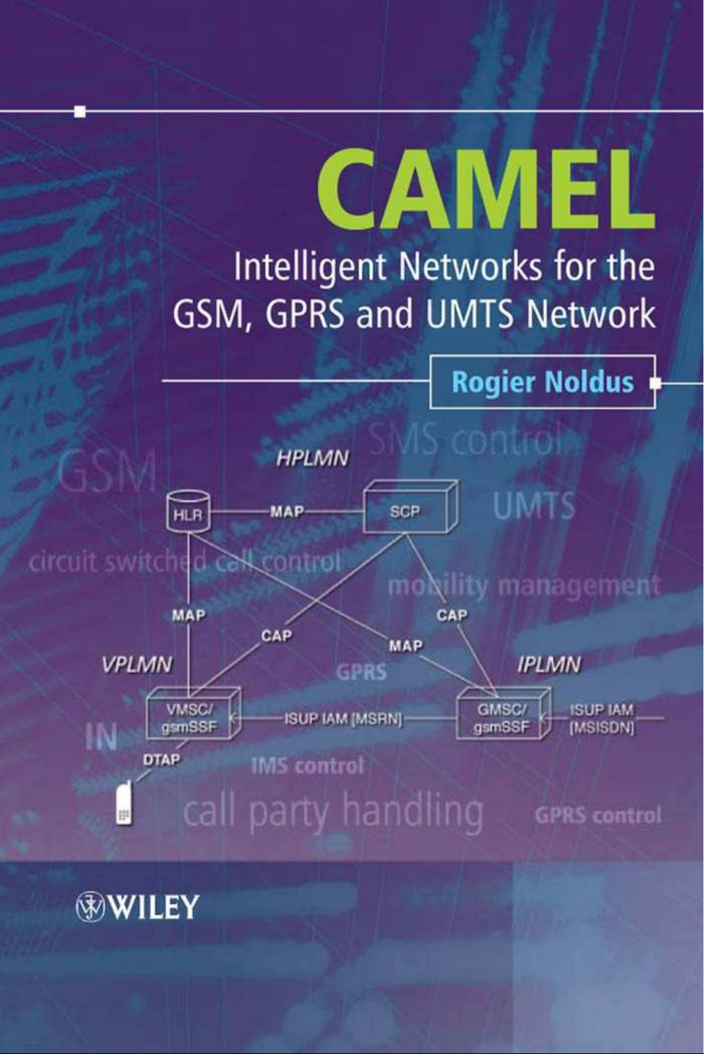
Figure 1.1 is a schematic overview of the main components in a GSM network. The various
interface labels are the formal names given to these interfaces. More details about these interfaces
are found in GSM TS 03.02 [26].
The GSM network consists mainly of the following functional parts:
• MSC – the mobile service switching centre (MSC) is the core switching entity in the network.
The MSC is connected to the radio access network (RAN); the RAN is formed by the BSCs and
BTSs within the Public Land Mobile Network (PLMN). Users of the GSM network are registered
with an MSC; all calls to and from the user are controlled by the MSC. A GSM network has
one or more MSCs, geographically distributed.
• VLR – the visitor location register (VLR) contains subscriber data for subscribers registered in
an MSC. Every MSC contains a VLR. Although MSC and VLR are individually addressable,
they are always contained in one integrated node.
• GMSC – the gateway MSC (GMSC) is the switching entity that controls mobile terminating
calls. When a call is established towards a GSM subscriber, a GMSC contacts the HLR of that
subscriber, to obtain the address of the MSC where that subscriber is currently registered. That
MSC address is used to route the call to that subscriber.
• HLR – the home location register (HLR) is the database that contains a subscription record for
each subscriber of the network. A GSM subscriber is normally associated with one particular
HLR. The HLR is responsible for the sending of subscription data to the VLR (during registration)
or GMSC (during mobile terminating call handling).
• CN – the core network (CN) consists of, amongst other things, MSC(s), GMSC(s) and HLR(s).
These entities are the main components for call handling and subscriber management. Other
main entities in the CN are the equipment identification register (EIR) and authentication centre
(AUC). CAMEL has no interaction with the EIR and AUC; hence EIR and AUC are not further
discussed.
• BSS – the base station system (BSS) is composed of one or more base station controllers (BSC)
and one or more base transceiver stations (BTS). The BTS contains one or more transceivers
(TRX). The TRX is responsible for radio signal transmission and reception. BTS and BSC are
connected through the Abis interface. The BSS is connected to the MSC through the A interface.
• MS – the mobile station (MS) is the GSM handset. The structure of the MS will be described in
more detail in a next section.
A GSM network is a public land mobile network (PLMN). Other types of PLMN are the time
division multiple access (TDMA) network or code division multiple access (CDMA) network. GSM
uses the following sub-division of the PLMN:
CAMEL: Intelligent Networks for the GSM, GPRS and UMTS Network Rogier Noldus
2006 John Wiley & Sons, Ltd
Page 23
2 CAMEL: Intelligent Networks for the GSM, GPRS and UMTS Network
To HLR from
other PLMN
MSC ISUP
E
HLR
D C
D
MSC
A
BSC
Abis Abis
BTS BTS
Um Um
Figure 1.1 GSM network architecture
ISUP ISUP
A
BSC
Um Um
MSMSMS
GMSC
Core
network
To/from other
network
Base station
system
Air interface
MS
• Home PLMN (HPLMN) – the HPLMN is the GSM network that a GSM user is a subscriber of.
That implies that GSM user’s subscription data resides in the HLR in that PLMN. The HLR
may transfer the subscription data to a VLR (during registration in a PLMN) or a GMSC (during
mobile terminating call handling). The HPLMN may also contain various service nodes, such as
a short message service centre (SMSC), service control point (SCP), etc.
• Visited PLMN (VPLMN) – the VPLMN is the GSM network where a subscriber is currently
registered. The subscriber may be registered in her HPLMN or in another PLMN. In the latter
case, the subscriber is outbound roaming (from HPLMN’s perspective) and inbound roaming
(from VPLMN’s perspective). When the subscriber is currently registered in her HPLMN, then
the HPLMN is at the same time VPLMN.
1
• Interrogating PLMN (IPLMN) – the IPLMN is the PLMN containing the GMSC that handles
mobile terminating (MT) calls. MT calls are always handled by a GMSC in the PLMN, regardless
of the origin of the call. For most operators, MT call handling is done by a GMSC in the HPLMN;
in that case, the HPLMN is at the same time IPLMN. This implies that calls destined for a GSM
subscriber are always routed to the HPLMN of that GSM subscriber. Once the call has arrived in
the HPLMN, the HPLMN acts as IPLMN. MT call handling will be described in more detail in
subsequent sections. When basic optimal routing (BOR) is applied, the IPLMN is not the same
PLMN as the HPLMN.
The user of a GSM network is referred to as the served subscriber ; the MSC that is serving that
subscriber is known as the serving MSC.Examplesare:
• mobile originated call – the MSC that is handling the call is the serving MSC for this call; the
calling subscriber is the served subscriber;
• mobile terminated call – the GMSC that is handling the call is the serving GMSC for this call;
the called subscriber is the served subscriber.
1
The CAMEL service requirement, GSM TS 02.78 [12] uses this strict definition. The term VPLMN is,
however, commonly used to denote any network other than the HPLMN.
Page 24

Introduction to GSM Networks 3
1.1 Signalling in GSM
The various entities in the GSM network are connected to one another through signalling networks.
Signalling is used for example, for subscriber mobility, subscriber registration, call establishment,
etc. The connections to the various entities are known as ‘reference points’. Examples include:
• A interface – the connection between MSC and BSC;
• Abis interface – the connection between BSC and BTS;
• D interface – the connection between MSC and HLR;
• Um interface – the radio connection between MS and BTS.
Various signalling protocols are used over the reference points. Some of these protocols for GSM
are the following:
• mobile application part (MAP) – MAP is used for call control, subscriber registration, short
message service, etc.; MAP is used over many of the GSM network interfaces;
• base station system application part (BSSAP) – BSSAP is used over the A interface;
• direct transfer application part (DTAP) – DTAP is used between MS and MSC; DTAP is carried
over the Abis and the A interface. DTAP is specified in GSM TS 04.08 [49];
• ISDN user part (ISUP) – ISUP is the protocol for establishing and releasing circuit switched
calls. ISUP is also used in landline Integrated Services Digital Network (ISDN). A circuit is the
data channel that is established between two users in the network. Within ISDN, the data channel
is generally a 64 kbit/s channel. The circuit is used for the transfer of the encoded speech or
other data. ISUP is specified in ITU-T Q.763 [137].
When it comes to call establishment, GSM makes a distinction between signalling and payload.
Signalling refers to the exchange of information for call set up; payload refers to the data that is
transferred within a call, i.e. voice, video, fax etc. For a mobile terminated GSM call, the signalling
consists of exchange of MAP messages between GMSC, HLR and visited MSC (VMSC). The
payload is transferred by the ISUP connection between GMSC and VMSC. It is a continual aim
to optimize the payload transfer through the network, as payload transfer has a direct cost aspect
associated with it. Some network services are designed to optimize the payload transfer. One
example is optimal routing.
1.2 GSM Mobility
Roaming with GSM is made possible through the separation of switching capability and subscription
data. A GSM subscriber has her subscription data, including CAMEL data, permanently registered
in the HLR in her HPLMN. The GSM operator is responsible for provisioning this data in the HLR.
The MSC and GMSC in a PLMN, on the other hand, are not specific for one subscriber group.
The switching capability of the MSC in a PLMN may be used by that PLMN’s own subscribers,
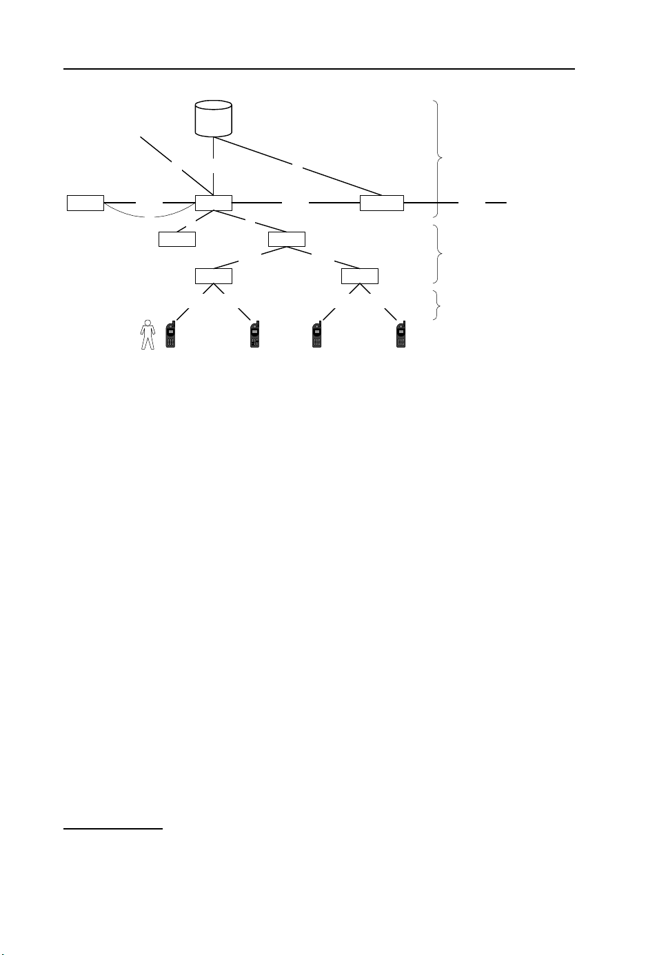
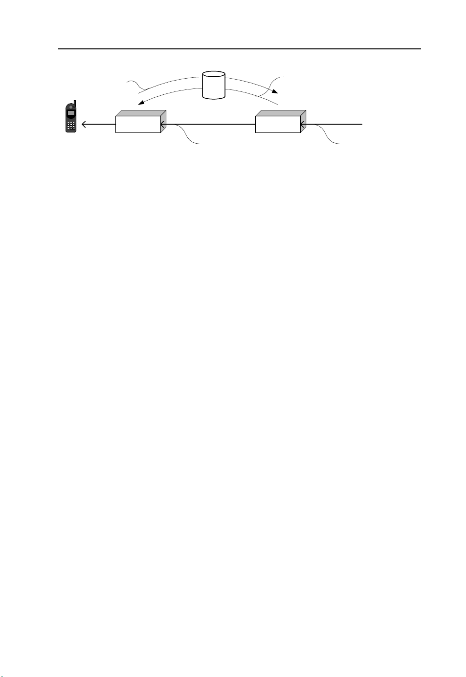
but also by inbound roaming subscribers; see Figure 1.2.
In Figure 1.2, the GSM user who is a subscriber of PLMN-A roams to PLMN-B. The HLR in
PLMN-A transfers the user’s subscription data to the MSC in PLMN-B. The subscriber’s subscription data remains in the MSC/VLR as long as she is served by a BSS that is connected to that
MSC. Even when the user switches her MS off and then on again, the subscription data remains
in the MSC. After an extended period of the MS being switched off, the subscription data will
be purged from the MSC. When the subscriber switches her MS on again, the subscriber has to
re-register with the MSC, which entails the MSC asking the HLR in the HPLMN to re-send the
subscription data for that subscriber.
Page 25
4 CAMEL: Intelligent Networks for the GSM, GPRS and UMTS Network
Transfer of subscription
data to MSC/VLR
HLR
PLMN-A
PLMN-B
MSC
MS
Subscriber roams to
other PLMN
Figure 1.2 Transfer of GSM subscription data for a roaming subscriber
MSC
When the subscriber moves from one MSC service area (MSC-1) to another MSC service area
(MSC-2), the HLR will instruct MSC-1 to purge the subscription data of this subscriber and will
send the subscription data to MSC-2.
1.3 Mobile Station
The MS, i.e. the GSM handset, is logically built up from the following components:
• mobile equipment (ME) – this is the GSM terminal, excluding the SIM card;
• subscriber identification module (SIM) – this is the chip embedded in the SIM card that identifies
a subscriber of a GSM network; the SIM is embedded in the SIM card. When the SIM card is
inserted in the ME, the subscriber may register with a GSM network. The ME is now effectively
personalized for this GSM subscriber; see Figure 1.3. The characteristics of the SIM are specified
in GSM TS 11.11. The SIM card contains information such as IMSI, advice of charge parameters,
operator-specific emergency number, etc. For the UMTS network an enhanced SIM is specified,
the universal subscriber identity module (USIM); refer 3GPP TS 31.102.
1.4 Identifiers in the GSM Network
GSM uses several identifiers for the routing of calls, identifying subscribers (e.g. for charging),
locating the HLR, identifying equipment, etc. Some of these identifiers play an important role for
CAMEL.
1.4.1 International Mobile Subscriber Identity
The international mobile subscriber identity (IMSI) is embedded on the SIM card and is used to
identify a subscriber. The IMSI is also contained in the subscription data in the HLR. The IMSI is
used for identifying a subscriber for various processes in the GSM network. Some of these are:
KPN
SIM + ME = MS
Figure 1.3 Components of the mobile station
Page 26

Introduction to GSM Networks 5
Maximum 15 digits
3 digits
MCC MNC MSIN
Figure 1.4 Structure of the IMSI
2 or 3 digits
• location update – when attaching to a network, the MS reports the IMSI to the MSC, which uses
the IMSI to derive the global title (GT) of the HLR associated with the subscriber;
• terminating call – when the GSM network handles a call to a GSM subscriber, the HLR uses
the IMSI to identify the subscriber in the MSC/VLR, to start a process for delivering the call to
that subscriber in that MSC/VLR.
• roaming charging – a VPLMN uses the IMSI to send billing records to the HPLMN of
a subscriber.
Figure 1.4 shows the format of the IMSI.
• mobile country code (MCC) – the MCC identifies the country for mobile networks. The MCC is
not used for call establishment. The usage of MCC is defined in ITU-T E.212 [129]. The MCC
values are allocated and published by the ITU-T.
• mobile network code (MNC) – the MNC identifies the mobile network within a mobile country
(as identified by MCC). MCC and MNC together identify a PLMN. Refer to ITU-T E.212 [129]
for MNC usage. The MNC may be two or three digits in length. Common practice is that, within
a country (as identified by MCC), all MNCs are either two or three digits.
• mobile subscriber identification number (MSIN) – the MSIN is the subscriber identifier within
aPLMN.
The IMSI is reported to the SCP during CAMEL service invocation. The IMSI may be needed,
for example, when identifying a country; countries in North America have equal country code
(country code = 1), but different MCC (e.g. Canada = 303; Mexico = 334).
1.4.2 Mobile Station Integrated Services Digital Network Number (MSISDN Number)
The MSISDN is used to identify the subscriber when, among other things, establishing a call to that
subscriber or sending an SMS to that subscriber. Hence, the MSISDN is used for routing purposes.
Figure 1.5 shows the structure of the MSISDN.
• country code (CC) – the CC identifies the country or group of countries of the subscriber;
• national destination code (NDC) – each PLMN in a country has one or more NDCs allocated to
it; the NDC may be used to route a call to the appropriate network;
• subscriber number (SN) – the SN identifies the subscriber within the number plan of a PLMN.
CC NDC SN
1, 2 or 3 digits
Maximum 15 digits
Figure 1.5 Structure of the MSISDN
Page 27
6 CAMEL: Intelligent Networks for the GSM, GPRS and UMTS Network
IMEI
IMEISV
The MSISDN is not stored on the subscriber’s SIM card and is normally not available in the
2
The MSISDN is provisioned in the HLR, as part of the subscriber’s profile, and is sent to
MS.
TAC FAC SNR
6 digits 2 digits 6 digits
TAC FAC SNR
6 digits 2 digits 6 digits 2 digits
Figure 1.6 Structure of IMEI and IMEISV
spare
igit
1d
SV
MSC during registration. The MSISDN is also reported to SCP when a CAMEL service is invoked.
One subscriber may have multiple MSISDNs. These MSISDNs are provisioned in the HLR. At
any one moment, only a single MSISDN is available in the MSC/VLR for the subscriber.
1.4.3 International Mobile Equipment Identifier
The international mobile equipment identifier (IMEI) is used to identify the ME [or user equipment
(UE) in UMTS network]. Each ME has a unique IMEI. The IMEI is hard-coded in the ME and
cannot be modified. Figure 1.6 shows the structure of the IMEI. The IMEI is not used for routing
or subscriber identification.
Refer to GSM TS 03.03 [27] for the type approval code (TAC), final assembly code (FAC)
and serial number (SNR). The software version (SV) may be included in the IMEI (‘IMEISV’) to
indicate the version of software embedded in the ME. The IMEI is always encoded as an eight-octet
string. As from CAMEL Phase 4, the IMEI(SV) may be reported to the SCP.
1.4.4 Mobile Station Roaming Number
The mobile station roaming number (MSRN) is used in the GSM network for routing a call to a
MS. The need for the MSRN stems from the fact that the MSISDN identifies a subscriber, but not
the current location of that subscriber in a telecommunications network. The MSRN is allocated to
a subscriber during MT call handling and is released when the call to that subscriber is established.
Each MSC in a PLMN has a (limited) range of MSRNs allocated to it. An MSRN may be allocated
to any subscriber registered in that MSC. The MSRN has the form of an E.164 number and can
be used by the GMSC for establishing a call to a GSM subscriber. An MSRN is part of a GSM
operator’s number plan. The MSRN indicates the GSM network a subscriber is registered in, but
not the GSM network the subscriber belongs to. Figure 1.7 shows how the MSRN is used for call
routing. The MSRN is not meant for call initiation. GSM operators may configure their MSC such
that subscribers cannot dial numbers that fall within the MSRN range of that operator.
1.5 Basic Services
All activities that may be done in the GSM network, such as establishing a voice call, establishing
a data call, sending a short message, etc., are classified as basic services. In order for a subscriber
to use a GSM basic service, she must have a subscription to that service.
2
GSM subscribers may program their MSISDN into the phone; this has, however, no significance for the
network.
3
Exceptions are Tele Service 12 (emergency call establishment) and Tele Service 23 (Cell Broadcast).
Subscribers do not need a subscription to these Tele Services to use them.
3
The handling of a basic
Page 28
Introduction to GSM Networks 7
GMSCVMSC
request MSRN
incoming call
return MSRN
Figure 1.7 Usage of MSRN during call establishment to a GSM subscriber
HLR
MSRN MSISDN
service is fully standardized. Hence, a subscriber may use a basic service in any GSM network
she roams to, provided that that basic service is supported in that network. The HLR will send
a list of subscribed basic services to the MSC/VLR, during registration. When a GSM subscriber
initiates a call, the MS supplies the serving MSC with a set of parameters describing the circuitswitched connection that is requested. These parameters are the bearer capability (BC), low-layer
compatibility (LLC) and high-layer compatibility (HLC), as will be described below. The MSC
uses the BC, LLC and HLC to derive the basic service for this call. The rules for deriving the basic
service from LLC, HLC and BC are specified in GSM TS 09.07 [55]. The MSC then checks whether
the subscriber has a subscription to the requested basic service, i.e. whether the subscription data
in the VLR contains that basic service. If the service is not subscribed to, then the MSC disallows
the call. The basic service is not transported over ISUP.
When a CAMEL service is invoked, the MSC reports the requested basic service to the SCP. The
SCP may use the indication of the requested basic service for call service processing. Examples
include:
• video calls may be charged at a higher rate than speech calls;
• for data calls and fax calls, the CAMEL service shall not play any announcements or tones.
Basic services are divided into two groups: tele services and bearer services.
1.5.1 Tele Services
Table 1.1 provides an overview of the available tele services (TS); see also GSM TS 02.03 [3].
1.5.2 Bearer Services
Table 1.2 provides an overview of the available bearer services (BS). The two bearer service groups
are sub-divided into a variety of bearer services with different characteristics. Refer to GSM TS
02.02 [2].
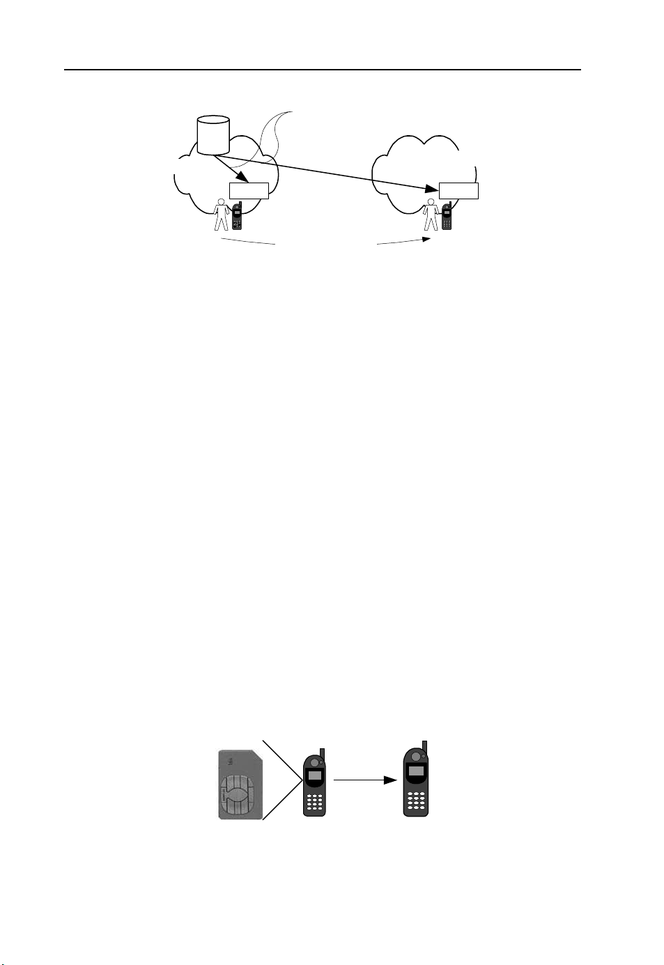
1.5.3 Circuit Bearer Description
Bearer capability, low-layer compatibility and high-layer compatibility are descriptors of a circuitswitched (CS) connection. When a GSM subscriber initiates a call, the BC, LLC and HLC are
transported from MS to MSC over DTAP. The MSC includes the parameters in the ISUP signal to
the destination. These parameters are also reported to the SCP during CAMEL service invocation.
That enables a CAMEL service to adapt the service logic processing to the type of call. Figure 1.8
shows the relation between LLC, HLC and BC on the DTAP and the corresponding parameters
on ISUP.
Page 29
8 CAMEL: Intelligent Networks for the GSM, GPRS and UMTS Network
Ta bl e 1 . 1 Tele services
Tele service Description Comment
11 Telephony This TS represents the normal speech call
12 Emergency calls The emergency call uses the characteristics of telephony
(TS11), but may be established without subscription
and bypasses various checks in the MS and in the MSC
21 Short message MT This TS relates to receiving an SMS. This TS is not sent
to the MSC/VLR. When an SMS is sent to the
subscriber, the HLR checks whether the destination
subscriber has a subscription to TS 21
22 Short message MO This TS relates to the sending of an SMS
23 Cell broadcast This TS relates to the capability of an SMS that is sent as
a broadcast SMS
61 Alternate speech and fax
group 3
This TS relates to the capability to establish a speech and
fax (group 3) call
62 Automatic fax group 3 This TS relates to the capability to establish a fax (group
3) call
91 Voice group call This TS relates to the capability to participate in a group
call as specified in GSM TS 03.68 [35]
92 Voice broadcast This TS relates to the capability to receive a voice
broadcast as specified in GSM TS 03.68 [35]
Ta bl e 1 . 2 Bearer services
Tele service Description Comment
20 Asynchronous data
bearer services
30 Synchronous data
bearer services
DTAP
(GSM TS 04.08)
Low layer compatibility
High layer compatibility
Bearer capability
May be used for asynchronous services from 300 bit/s
to 64 kbit/s.
May be used for synchronous services from 1.2 to
64 kbit/s. This BS may be used, amongst other things,
for multimedia services such as video telephony.
MSC
Access transport [low l ayer compatibility]
User teleservice information
User service information
ISUP
(ITU-T Q.763)
4
Figure 1.8 Transfer of LLC, HLC and BC through DTAP and ISUP
• Low-layer compatibility – the LLC is transported transparently between the calling entity and
called entity; it may be used by the respective entities to adapt codecs for interworking purposes.
LLC describes mainly characteristics related to the data transfer.
4
3GPP Rel-7 may include a dedicated bearer service for video telephony.
Page 30

Introduction to GSM Networks 9
• High-layer compatibility – the HLC is also transported transparently between the calling entity
and called entity; it is used to describe the requested service, such as telephony, Fax, video
telephony, etc.
• Bearer capability – the BC describes the characteristics of the 64 kbit/s circuit requested for
the call.
1.6 Supplementary Services
Supplementary services (SS) in GSM are a means of enriching the user experience. An SS may,
for example, forward a call in the case of no reply from the called party, bar certain outgoing or
incoming calls, show the number of the calling party to the called party, etc. In order to use an
SS, a GSM user needs a subscription to that SS. The subscription to supplementary services is
contained in the HLR and is sent to the MSC/VLR during registration. The supplementary services
are fully standardized. A GSM subscriber can therefore use her supplementary services in any GSM
network, provided that the network supports these supplementary services, and have the same user
experience.
Ta bl e 1 . 3 GSM supplementary services
SS group Supplementary services GSM TS
Line identification Calling line identification presentation (CLIP) 02.81 [13]
Calling line identification restriction (CLIR)
Connected line presentation (COLP)
Name identification Calling name presentation (CNAP) 02.96 [24]
Call forwarding Call forwarding – unconditional (CFU) 02.82 [14],
Call offering Explicit call transfer (ECT) 02.91 [22]
Call completion Call waiting (CW) 02.83 [15],
Multi-party Multi-party call (MPTY) 02.84 [16]
Community of interest Closed user group (CUG) 02.85 [17]
Charging Advice of charge – information (AOCI) 02.86 [18]
Additional information transfer User-to-user signalling – service 1 (UUS1) 02.87 [19]
Call barring Barring of all outgoing calls (BAOC) 02.88 [20]
Call priority enhanced multi-level precedence and pre-emption
Connected line restriction (COLR)
Call forwarding – busy (CFB)
Call forwarding – no reply (CFNRY)
Call forwarding – not reachable (CFNRC)
Call deflection (CD) 02.72 [11]
Call hold (CH)
Call completion to busy subscriber (CCBS) 02.93 [23],
Multi-call (MC) 22.135 [69]
Advice of charge – charge (AOCC)
User-to-user signalling – service 2 (UUS2)
User-to-user signalling – service 3 (UUS3)
Barring of outgoing international calls (BOIC)
Barring of outgoing international calls except to the
home country (BOIC-exHc)
Barring of all incoming calls (BAIC)
Barring of all incoming calls when roaming
(BICROAM)
02.67 [10]
(eMLPP)
a
a
For the multi-call service, there is no GSM TS available, but only a 3GPP TS (22.135).
Page 31

10 CAMEL: Intelligent Networks for the GSM, GPRS and UMTS Network
Supplementary services may be provisioned for an individual basic service or for a group of
basic services, e.g. a subscriber may have barring of all outgoing calls for all tele services and all
bearer services, except SMS (tele service group 20). Such a subscriber is barred from establishing
outgoing calls (except emergency calls), but may still send short messages. Some supplementary
services may be activated or deactivated by the user. Examples include call forwarding and call
barring. An operator may decide to bar certain subscribers or subscriber groups from modifying
their supplementary services.
Table 1.3 shows the Supplementary Services. They are combined in service groups. Subscriptions
are per individual Supplementary Service. The right-most column indicates the GSM technical
specifications (TS) that specify the service requirement for the respective Supplementary Service(s).
The chapters on CAMEL Phases 1– 4 describe the interaction between CAMEL and the various supplementary services. Not all GSM networks support all supplementary services. Many of
the supplementary services in GSM have equivalent supplementary services in ISDN. The ISDN
supplementary services are described in ITU-T recommendations.
GSM TS 02.03 [3] describes how the supplementary services may be activated, deactivated and
invoked.
Page 32

2
Introduction to Intelligent Networks
Intelligent networks (IN) is a technique that augments digital telecommunication networks with a
method to lift the control over CS calls to a higher-layer control platform. These digital networks,
which are based on signalling principles defined by ISUP, may include networks such as the
integrated service digital network (ISDN), the public switched telephone network (PSTN) and the
PLMN. Applying IN to any of these networks has in common that call establishment is intercepted
at a designated node in the network. Control over the call is handed over to a control platform.
The control platform determines how the establishment of this call shall continue. This is depicted
in Figure 2.1.
The SCP forms the control platform for IN. The IN control protocol is the capability set that
enables the operator to assert control over the call. Various IN standards have defined an IN protocol;
CAMEL is one such standard. The exchange is located in the core network and may be a node
such as a local exchange (LE), transit exchange (TE) or MSC. The SCP is located in the service
layer. The service layer may contain a multitude of nodes, but for IN the SCP is the main entity
through which control over the call may be asserted.
2.1 History of Intelligent Networks
Development of IN in the form that it is currently known started in the mid-1980s. One of the
first IN standards was Bellcore’s1advanced IN (AIN). AIN was developed as an IN standard for
landline digital networks. A later IN standard was the wireless IN (WIN), which targets the mobile
networks, amongst which is the personal communication system (PCS). WIN was later also applied
to the TDMA and code division multiple access (CDMA) networks.
In the early-1990s, the International Telecommunication Unit – Telecommunications (ITU-T)
developed its first capability set (CS) standard, CS1. CS1 is the IN control protocol from which
further IN standards were derived. IN application part (INAP) is often used as generic term to
denote the IN control protocol between SCP and the core network. The ITU-T has subsequently
published CS2, CS3 and CS4, all of which are successors and enhancements to CS1.
The European Telecommunication Standardization Institute (ETSI) has used the work from ITUT to endorse IN standards for the European market. The ETSI CS standards are referred to as Core
INAP CS1, Core INAP CS2 and Core INAP CS3.
The present book does not aim to provide in-depth description of the original IN standards as
developed by Bellcore, ITU-T and ETSI. Rather, the chapters in this book describe how CAMEL,
2
1
Bell Communications Research, North American laboratory, providing support to the Bell Companies.
2
Other ITU sectors include radio communications (ITU-R) and telecom development (ITU-D).
CAMEL: Intelligent Networks for the GSM, GPRS and UMTS Network Rogier Noldus
2006 John Wiley & Sons, Ltd
Page 33

12 CAMEL: Intelligent Networks for the GSM, GPRS and UMTS Network
service
SCP
IN control protocol
Calling party Called party
ExchangeSignalling Signalling
Figure 2.1 IN control to basic call
logic
being an IN standard, is developed for the GSM network specifically. The reader who is acquainted
with the original IN standards will recognize many of the fundamental principles of these standards,
when reading the present book. However, CAMEL has been developed specifically for GSM (and
subsequently for GPRS and UMTS); therefore, it contains many capabilities that are not found in
any of the traditional IN standards.
For an in-depth description of traditional IN, the reader is referred to The Intelligent Network
Standards [173] and The Intelligent Network [174].
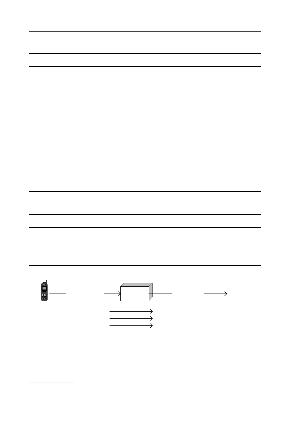
2.2 Principles of Intelligent Networks
One pivotal principle of IN is the interaction between the core network signalling protocol (e.g.
ISUP) and the IN control protocol (INAP). This is depicted in Figures 2.2 – 2.4. Figure 2.2 shows
the network components for a typical mobile-to-mobile call in the GSM network; Figure 2.3 shows
the ISUP signal sequence flow of this call; Figure 2.4 shows how IN interacts with this signalling,
at designated points in the sequence flow.
In Figure 2.2, the call is established by the mobile station of the A-party (MS-A), through the
VMSC of the A-party (VMSC-A), the GMSC for the B-party (GMSC-B), the VMSC of the B-party
(VMSC-B) to the MS of the B-party (MS-B). The ISUP messages between VMSC-A, GMSC-B
and VMSC-B are listed in the Appendix. Direct transfer application part (DTAP) is the call control
protocol used between MS and the MSC.
At designated points in the message sequence flow, interaction between the MSC and the SCP
takes place. These interactions enable the SCP to influence the processing of the call. In the example
in Figure 2.4, interaction takes place at the following points:
• Call establishment – when MSC-A starts call establishment, as a result of receiving a setup
message over the air interface from the A-party, it invokes an IN service in the SCP. The
SCP
MS-A MS-B
INAP
VMSC-A GMSC-B VMSC-BDTAP ISUP ISUP DTAP
Figure 2.2 Network architecture for mobile-to-mobile call
Page 34

Introduction to Intelligent Networks 13
MS-A VMSC-A GMSC-B VMSC-B MS-B
Setup
Progress IAM[MSRN]
Alerting Connect
Connect
IAM[MSISDN]
Optional: ACM
ACM/CPG
ANM
ACM
ANM
Setup
Alerting
Releas e
REL
REL
Releas e
Figure 2.3 Example of ISUP message sequence flow
MS-A VMSC-A GMSC-B VMSC-B MS-B SCP
Setup
IAM
ACM
Alerting
ANM
Connect
Releas e
REL
Service invocation + event notification
IAM
ACM
ANM
Event notification + service termination
REL
Call continuation
Setup
Alerting
Event notification
Connect
Event notification
Releas e
Figure 2.4 IN control for basic mobile-to-mobile call
invocation of an IN service entails the establishment of an IN dialogue between the MSC and
the SCP. It is through this dialogue that the SCP can control the call.
• Alerting – when the MSC-A receives an indication that the B-party’s terminal is alerting (‘ring-
ing’), it sends a notification to the SCP.
• Answer – when the MSC-A receives an indication that the B-party’s terminal has answered the
call, it sends a notification to the SCP.
• Disconnect – when the MSC-A receives an indication that one of the parties has released the
call, it sends a notification to the SCP and terminates the IN dialogue. Closing the IN dialogue
also has the effect of terminating the IN service.
At service invocation and event notification, the MSC copies information elements from the signalling message (i.e. the ISUP message) to the IN control message. The SCP decides how to control
this call, based on the received information. The SCP may decide to allow the call to continue
unmodified or to allow the call to continue with modified information. The latter may be done
by providing the MSC with specific information elements that replace corresponding information
Page 35

14 CAMEL: Intelligent Networks for the GSM, GPRS and UMTS Network
elements in designated ISUP messages. The SCP may retain control over the call for the entire call
duration or may relinquish control at an earlier moment. When the SCP relinquishes control over
the call, i.e. terminates the IN service, the call may continue without IN control.
The IN service invocation, depicted in Figure 2.4 by the first arrow from VMSC-A to SCP, is
based on criteria present in the exchange. In this example, VMSC-A has determined that, for this
call, an IN service shall be invoked. Traditional IN does not define stringent triggering criteria. An
operator may define these criteria in an MSC as deemed suitable. Examples include:
• number-based triggering – the MSC triggers an IN service for certain numbers or number ranges,
e.g. calls to numbers starting with 0800 trigger a free-phone service;
• trunk-based triggered – calls that arrive over a particular trunk (‘trunk’ is generic term for the
transmission channel between two switching nodes) trigger an IN service, e.g. all calls arriving
from another network trigger an incoming call-screening service;
• subscription-based triggering – calls from a particular subscriber trigger an IN service, e.g. all
calls from subscribers belonging to a certain company trigger a virtual private network (VPN)
service.
The exchange from where an IN service is invoked needs configuration for various other characteristics of the IN service. These characteristics include:
• the address of the SCP where the IN service resides; the service invocation will be sent to that
address;
• the protocol that will be used for this IN service;
• the information elements that will be provided to the IN service.
All of these aspects of the IN service are configured in the exchange from where the IN service
may be invoked. The operator owning the exchanges may decide on this configuration, to suit that
operator’s IN services.
2.3 Service Switching Function
The IN control protocol at the exchange is handled by the service switching function (SSF). The
SSF passes call control from the exchange to the SCP and relays instructions from the SCP back
to the exchange. All IN protocol aspects are handled by the SSF. Figure 2.5 depicts the SSF in
an MSC.
At IN service invocation, the SSF copies information from the access protocol (e.g. ISUP or
DTAP) onto the INAP message that is used to invoke the IN service. When the SSF receives
instruction from SCP, it copies information received from the SCP on to the call control protocol.
INAP
Internal control protocol
SSF
DTAP ISUP
Figure 2.5 SSF inside an MSC
MSC
Page 36

Introduction to Intelligent Networks 15
ISUP
SCP
INAP
MSC/SSF
MSC
MSC
Centralized IN servic e invocation Distributed IN service invocation
Figure 2.6 Centralized vs distributed IN control
MSC
MSC/SSF
SCP
INAP INAP
INAP
MSC/SSFISUP
MSC/SSF
In a GSM network, each MSC may be equipped with an SSF or only designated MSCs may be
equipped with an SSF (Figure 2.6).
A network may have a mix of centralized IN control and distributed IN control, depending
on the type of IN service. Centralized IN control requires less investment in SSF, but may lead
to more ISUP signalling since calls need to be routed through a designated MSC for IN service
invocation. Centralized IN control may also be applied when the designated MSC has specific IN
control capability that cannot be offered by the other MSCs in the network. This method may, for
example, be applied in a network with core network equipment from different vendors.
2.4 Service Control Function
The service control function (SCF) is the functional entity residing in the SCP. It forms an application in the SCP that facilitates the execution of IN services. The SCP is an addressable node
in the SS7 network. Other nodes in the network may communicate with the SCP through the SS7
signalling protocol.
For both CAMEL and INAP, the behaviour of the SCF is specified in less detail than the
behaviour of the SSF. The rationale is that, once the SCF has gained control over a call, it may
decide how the call shall continue. The SCF supports the IN protocol (e.g. INAP), but the behaviour
of the service logic is operator-specific.
2.5 Basic Call State Model
A fundamental concept for IN control is the basic call state model (BCSM). When a call is processed
by an exchange, the call goes through a number of pre-defined phases. These phases of the call are
described in the BCSM. The BCSM generally follows the ISUP signalling of a call. ISUP messages
received by the exchange result in the transition from one BCSM state to another. The definition
of the BCSM enables the MSC to interact with the SSF at defined points in the call. The SSF may
in its turn contact the SCP at these points in the call.
The BCSM contains detection points (DP) and points in call (PIC). This is reflected in Figure 2.7.
The PIC indicates the state of the call, i.e. analysis, routing, alerting and active. A DP is associated
with a state transition. When the call reaches a certain PIC, the BCSM first processes the DP that is
associated with the transition to that PIC, e.g. when the call is in the alerting phase and an answer
event is received over ISUP, the BCSM processes the DP that is associated with the answer event.
After the processing of the DP is complete, the BCSM transits to the active PIC.
The BCSM describes a model according to which an exchange may handle the establishment of
a call. For each call that is handled by an exchange a process is started that behaves as defined by
Page 37

16 CAMEL: Intelligent Networks for the GSM, GPRS and UMTS Network
Transition
e.g. Answer
DP
Point in call
(e.g. active call)
Figure 2.7 Elements of the BCSM: PIC and DP. Reproduced from GSM TS 03.78 v5.8.0 Figure 7.1/1, by
permission of ETSI
Transition
the BCSM. This is commonly described as ‘an instance of the BCSM is created’ or ‘the BCSM
is instantiated’. ISUP messages passing through this exchange may have the result that the BCSM
instance for this call transits from one state to another state, e.g. when a call is in the setup phase
and the exchange receives the ISUP answer message, the BCSM instance transits to DP answer.
The SSF in that exchange may notify the SCP and, depending on the IN service logic behaviour,
continue processing the ISUP answer message. Practically, this means the forwarding of the answer
message in the backwards direction to the originator of the call.
Core INAP CS1 has defined two types of BCSM: the originating call BCSM and the terminating
call BCSM. These BCSMs are based on the ISUP messages used for call establishment and on the
digital subscriber signalling 1 (DSS1) protocol. DSS1 is the access protocol used between ISDN
terminal and ISDN network. The BCSMs that are defined in CAMEL are derived from the Core
INAP CS1 BCSMs. These CAMEL BCSMs are described in Chapters 3 – 6.
IN defines four DP types:
• Trigger detection point – request (TDP-R): when the BCSM instance for a call transits to a DP
that is defined as TDP-R, an IN service may be started at that point. This entails the internal
SSF notifying the SCF and waiting for further instructions. The call processing in the MSC is
halted until the SSF has received instructions from the SCF. TDPs are statically defined in an
exchange. By defining different DPs in the BCSM as TDP, the exchange may invoke an IN
service at different points in the call.
• Trigger detection point – notify (TDP-N): the TDP-N is a variant of the TDP-R. An IN service
may be triggered from a DP that is defined as TDP-N as opposed to TDP-R. The SSF will in
that case not wait for instructions from the SCP, but will return the call control immediately to
the MSC. As a result the call processing is not halted. The SCP has not gained control over the
call; the SCP was merely notified about the occurrence of the call event. The use of TDP-N is
not very common for IN. CAMEL defines TDP-R, but not TDP-N.
• Event detection point – request (EDP-R): When an IN service is invoked, it may arm DPs within
the BCSM as an event detection point (EDP). Arming a DP entails that the IN service instructs
the SSF to monitor for the occurrence of the event associated with the DP. When the event
occurs, the SSF notifies the SCP. If the DP is armed as EDP-R, the SSF halts call processing
after the notification and waits for instructions from the SCP. The reporting of an event that was
armed as an EDP-R is referred to as interrupt mode.
• Event detection point – notify (EDP-N): The IN service may arm an EDP in interrupt mode
(EDP-R) or in notify mode (EDP-N). When a DP is armed as an EDP-N, the SSF reports the
occurrence of the event associated with the DP, but the SSF does not halt call processing. Instead,
the SSF instructs the MSC to continue call processing.
An IN service normally keeps a mirror image of the BCSM instance in the SSF for the call that the
IN service is controlling. In this way, the IN service knows the phase of the call and which events
Page 38

Introduction to Intelligent Networks 17
Dialogue handler
SSF
DTAP ISUP
MSC
Figure 2.8 IN dialogue handler
IN dialogue
SCF
may occur. In order to keep this mirror image of the BCSM, the IN service will arm the DPs in
the BCSM, so as to receive a notification when a state transition occurs in the BCSM. When a DP
is not armed, the DP is said to be transparent.
2.6 Dialogue Handling
The invocation of an IN service involves the establishment of an IN dialogue between SSF and
SCF. SSF and SCF start a process that governs this dialogue (Figure 2.8).
The IN dialogue between SSF and SCF facilitates the exchange of instructions and notifications
between SSF and SCF. When the IN service terminates, the IN dialogue is closed. Two methods
exist for closing the IN dialogue:
• Pre-arranged end – when communication has taken place between SCF and SSF and both entities
can deduce that, for this call, there will not be any further communication through this IN
dialogue, then both entities may terminate the dialogue without informing the other entity.
• Basic end – an entity may explicitly terminate the IN dialogue by sending a dialogue closing
notification to the other entity.
Figure 2.9 contains examples that reflect both methods for dialogue termination. The transaction
capability (TC) messages (TC
IN service is started by the SSF by sending the initial DP operation to the SCF. The IN service
responds by sending the continue operation, which instructs the SSF to continue call establishment.
In the pre-arranged end example, the SCF does not explicitly close the IN dialogue. However, since
the SCF did not arm any of the DPs in the BCSM, there will not be any further communication
between SSF and SCF through this IN dialogue. The SSF and SCF therefore decide to close the
IN dialogue. In the basic end example, the SCF instructs the SSF to continue call establishment
and at the same time instructs the SSF to close the IN dialogue. Section 2.9 presents further details
related to the signalling between SSF and SCF.
Begin, TC Continue, TC End) are explained in a later section. The
2.6.1 DP Arming/Disarming Rules
As described above, the DPs in the BCSM are the defined contact points between SSF and SCF.
Arming and disarming DPs in the BCSM is a tool used by the IN service to keep informed about
SSF SCF
TC_Beging[Initial DP]
TC_Continue[Continue]
pre-arranged end basic end
Figure 2.9 Pre-arranged end vs basic end
SSF SCF
TC_Beging[Initial DP]
TC_End[Continue]
Page 39

18 CAMEL: Intelligent Networks for the GSM, GPRS and UMTS Network
the phase of the call and to maintain or close the IN dialogue. A set of DP arming and disarming
rules are defined below.
• TPD arming – TDPs are statically armed in the exchange. The operator may decide for which
calls an IN service is invoked and at which DP in the BCSM for that call.
• EDP arming – when an IN service is invoked from a particular TDP in the BCSM, the IN service
may dynamically arm DPs in the BCSM as EDP-N or EDP-R. The arming of a DP as EDP is
valid only for the duration of the IN service. The IN protocol that is used for the IN service
determines which DPs are available in the BCSM and whether these DPs may be armed as
EDP-N or EDP-R.
• EDP disarming – when a DP is armed as EDP, it may be disarmed in various ways: (1) the
IN service may explicitly instruct the SSF to disarm the DP; (2) when the DP occurs, the SSF
disarms the DP; the IN service may re-arm the DP, if needed;
3
(3) the occurrence of a particular
DP in the SSF may result in the implicit disarming of other DPs in the BCSM; CAMEL specifies
strict rules for this form of implicit disarming; and (4) when a call or call leg is released, all DPs
associated with that call or call leg are disarmed.
2.6.2 Control vs Monitor Relationship
The SSF and SCF maintain a relationship through the IN dialogue. The relationship is a means of
describing the level of control the SCF has over the call. A relationship exists between SSF and
SCF under the following conditions:
• the SSF has reported a TDP-R or EDP-R to the SCP and is waiting for instructions from the
SCP; or
• at least one DP in the BCSM is armed as EDP-N or EDP-R; or
• the SCP has requested the SSF to send a charging report; or
• the SCP has requested the SSF to send a call information report.
The charging report and call information report are described in Chapter 4. Two forms of relationship are defined.
2.6.2.1 Control Relationship
When a control relationship exists between SSF and SCF, the IN service may take actions like
releasing the call. A control relationship exists under the following conditions:
• the SSF has reported a TDP-R or EDP-R to the SCP and is waiting for instructions from the
SCP; or
• at least one DP is armed as EDP-R.
When the BCSM transits to a DP that is armed as EDP-R, the SSF automatically disarms that DP.
The control relationship between the SSF and SCF remains at least until the end of the processing
of this DP. For example, IN service may arm the disconnect event (indicating that the calling or
called party has terminated the call) as EDP-R. When the disconnect event occurs, the SSF reports
the event to the SCP and waits for instructions. The SSF has, in accordance with DP disarming
rules, disarmed the disconnect event. Hence, there is currently no DP armed for this call. However,
as long as the SCP is busy processing the disconnect event, which was reported in interrupt mode,
the control relationship exists.
3
In CAMEL Phase 4, ‘automatic re-arming’ is introduced for selected DPs.
Page 40

Introduction to Intelligent Networks 19
2.6.2.2 Monitor Relationship
When a monitor relationship exists between SSF and SCF, the IN service may keep informed
about the call progress, but cannot assert any control over the call. It cannot, for example, order
a follow-on call when call establishment fails. When a relationship exists between SSF and SCF,
but does not qualify for a control relationship, it is a monitor relationship. A control relationship
may downgrade to a monitor relationship, but not vice versa.
2.7 Evolution of the CAMEL Standard
CAMEL is a natural evolution of the IN standards that were defined by Bellcore, the ITU-T and
ETSI. Many of the concepts that are defined for Core INAP CS1 also apply to CAMEL. Hence,
CAMEL is by definition an IN standard.
the GSM network standard. When GSM development started in the late 1980s, the concept of IN
was already in place. When operators started to deploy GSM in the early 1990s, IN was still mainly
used for fixed line networks, such as PSTN and ISDN. When the need arose for more advanced
services than were available in the GSM network, operators started using the existing IN standards.
Over and above, vendors introduced their specific enhancements to the IN standards.
This practice had the following aspects:
• IN capability related to charging is largely undefined in the existing standards; these capabilities
may be defined by the equipment vendor that implements the IN standard.
• Triggering methods are not defined; hence, no unified set of rules exists that indicates when an
exchange such as an MSC will invoke an IN service for a subscriber.
• The existing IN standards were developed for wireline networks. Many GSM-specific network
aspects are not supported in the existing IN.
• The existing IN standard does not support the mobility aspect of GSM, i.e. subscribers roaming
to other GSM networks and using their basic services and supplementary services in those other
networks.
4
The need for CAMEL grew during the development of
To address the above issues, ETSI introduced an IN standard specifically for the GSM network.
This GSM-specific IN standard, i.e. CAMEL, forms an integral part of the ETSI GSM standards.
The first version of CAMEL was included in the GSM phase 2+ release 96 (GSM R96). Table 2.1
shows the relation between GSM releases and CAMEL phases. The table also shows the evolution
of the GSM standard into the third generation network standard. Table 2.1 does not consider 3GPP
releases beyond Rel-7.
Major distinctive aspects of the CAMEL IN standard, compared with traditional IN standards,
include:
• The IN control protocol from CAMEL, the CAMEL application part (CAP), is fully specified,
including charging capability.
• CAMEL may be used in GSM networks consisting of equipment from multiple vendors.
• CAMEL services may be used for subscribers in their home network and for roaming subscribers.
• The CAMEL IN standard is tailored to the GSM network.
• CAMEL is evolving with further development in the GSM network.
2.7.1 Third-generation Partnership Project
Although ETSI is a regional (European) standardization institute, the GSM network standard developed by ETSI, including the CAMEL standard, is used by operators worldwide. The GSM network
4
IN is often used as a term to refer to non-CAMEL IN standards such as ETSI CS1.
Page 41

20 CAMEL: Intelligent Networks for the GSM, GPRS and UMTS Network
Ta bl e 2 . 1 Overview of GSM releases and CAMEL phases
GSM release Organization Year CAMEL
phase
GSM phase 1 ETSI 1992 –
GSM phase 2 ETSI 1994 –
GSM phase 2+ R96 ETSI 1996 Phase 1
GSM phase 2+ R97 ETSI 1997 Phase 2
GSM phase 2+ R98 ETSI 1998 Phase 2 CAMEL phase 2 in R98 is identical to
CAMEL Phase 2 in R97
3G network R99 3GPP 1999 Phase 3
3G network Rel-4 3GPP 2000 Phase 3 CAMEL phase 3 in Rel-4 is identical to
CAMEL phase 3 in R99
3G network Rel-5 3GPP 2002 Phase 4
3G network Rel-6 3GPP 2004 Phase 4 CAMEL phase 4 in Rel-6 is enhanced,
compared to Rel-5
3G network Rel-7 3GPP 2006 Phase 4 CAMEL phase 4 in Rel-7 is enhanced,
compared with Rel-6
Comment
development was taken over by the Third Generation Partnership Project (3GPP) from release R99
onwards. 3GPP also took over the maintenance of the existing GSM specifications. 3GPP is a
consortium of various organizations, jointly developing the specifications for the Third Generation
(3G) mobile network. The 3G mobile network is a global standard. Table 2.2 shows the organizations that form 3GPP. 3GPP has a well-defined structure of working groups, each of which carries
responsibility for developing specific aspects of the mobile network. Table 2.3 lists the working
groups responsible for the CAMEL standardization.
Ta bl e 2 . 2 3GPP organizations
Organization Acronym Region
Association of Radio Industries and Businesses ARIB Japan
Alliance for Telecommunications Industry Solutions ATIS North America
China Communications Standards Association CCSA China
European Telecommunications Standardisation Institute ETSI Europe
Telecommunications Technology Association TTA Korea
Telecommunications Technology Committee TTC Japan
Ta bl e 2 . 3 3GPP working groups for CAMEL standardization
Working group Task
Service architecture – working group 1 (SA1) Defining service requirements
Service architecture – working group 2 (SA2) Overall network architecture
Service architecture – working group 5 (SA5) Network management and charging aspects
Core network – working group 2 (CN2) Overall CAMEL development responsibility
Core network – working group 4 (CN4) Core network protocols
Page 42

Introduction to Intelligent Networks 21
CAMEL was mainly developed by working group CN2. In 2005, the tasks of the CN2 working
group and the CN4 working group were bundled into a new group, ‘Core network and terminals – working group 4’ (CT4).
2.7.2 CAMEL Standards and Specifications
CAMEL is defined in the following set of technical specifications (TS).
2.7.2.1 For GSM R96, R97 and R98
• GSM TS 02.78 [12] – this TS specifies the service requirements; it is also known as ‘stage 1’.
• GSM TS 03.78 [38] – this TS specifies the technical implementation, information flows, sub-
scription data etc; this TS is also referred to as ‘stage 2’.
• GSM TS 09.78 [56] – this TS specifies the CAMEL application part (CAP) which is the IN
protocol used between SCF and GSM/3G core network entities such as MSC/SSF. This TS is
known as ‘stage 3’.
The distinction between stage 1 specification, stage 2 specification and stage 3 specification is a
common method in 3GPP.
2.7.2.2 For 3G R99, Rel-4, Rel-5, Rel-6 and Rel-7
• 3GPP TS 22.078 [66] – this TS specifies the service requirements; it is the 3G successor of GSM
TS 02.78 [12].
• 3GPP TS 23.078 [83] – this TS specifies the technical implementation; it is the 3G successor of
GSM TS 03.78 [38].
• 3GPP TS 29.078 [106] – this TS specifies CAP; it is the 3G successor of GSM TS 09.78 [56].
• 3GPP TS 23.278 [93] – this TS specifies the technical implementation of CAMEL control of
IMS; this TS is applicable from 3G Rel-5 onwards. There is no separate stage 1 specification
for CAMEL control of IMS.
• 3GPP TS 29.278 [111] – this TS specifies the CAP that is used for CAMEL control of IMS;
this TS is applicable from 3GPP Rel-5 onwards.
The different GSM and 3G releases use distinctive version numbers for the specifications. This
helps designers and implementers identify the specific document that is needed for the CAMEL
specification in a specific GSM or 3G release. Table 2.4 lists the document version number per
GSM or 3GPP release.
Ta bl e 2 . 4 GSM and 3G specification versions
GSM release TS version 3G release TS version
GSM R96 5.y.z 3GPP R99 3.y.z
GSM R97 6.y.z 3GPP Rel-4 4.y.z
GSM R98 7.y.z 3GPP Rel-5 5.y.z
3GPP Rel-6 6.y.z
3GPP Rel-7 7.y.z
Page 43

22 CAMEL: Intelligent Networks for the GSM, GPRS and UMTS Network
When amendments are approved for a particular TS, the suffix of the version number (.y.z) is
increased. For technical corrections, the .y part of the version number is normally stepped; for
editorial corrections, the .z part of the version number is normally stepped.
2.7.2.3 Relation Between Stage 2 TS and Stage 3 TS
The CAMEL stage 2 specification (03.78/23.078) specifies information flows and the CAMEL
stage 3 specification (09.78/29.078) specifies the syntax of CAP. There is often confusion about
the priority of these specifications where it comes to optionality of information elements that may
be carried in CAMEL operations. The rule is as follows:
• stage 2 defines semantics for the information flows (IF) and information elements (IE) that may
be sent between gsmSSF and gsmSCF;
• stage 3 defines the syntax of conveying these IEs, encoded as operation parameters, through the
CAP protocol.
When stage 2 and stage 3 seem to be contradicting for a particular IE/parameter, then stage 2 is
leading. For example:
(1) GSM TS 03.78 [38] specifies for the Initial DP (IDP) IF that IMSI is a mandatory IE. GSM
TS 09.78 [56] specifies, however, that the corresponding parameter in the initial DP operation
is syntactically optional. Stage 2 is leading in this regard, meaning that the initial DP operation
shall always contain IMSI.
(2) GSM TS 03.78 [38] specifies that an IN service may provide a no answer timer value in the
range 10 – 40 s. The corresponding parameter in GSM TS 09.78 [56], application timer, has a
range of 0 – 2047 s, but again, stage 2 is leading with a range of 10– 40 s. A parameter that
is specified in stage 3 may be used by different stage 2 information flows. These stage 2
information flows may specify different restrictions on the use of this parameter.
2.8 Principles of CAMEL
Possibly the most important characteristic of CAMEL is its mobility aspect. A GSM operator may
offer an IN service to its subscribers; this IN service may be used in identical manner in the home
network and when roaming in other networks. This is accomplished by strict specification of the
gsmSSF, the SSF entity for GSM networks, in combination with CAMEL subscription data. In
order for a subscriber to use a CAMEL service, the subscriber shall have CAMEL subscription
data in her GSM profile in the HLR. When the subscriber registers in a PLMN, the HLR may
transfer the CAMEL subscription data to the MSC/VLR. When that subscriber originates a call
from that PLMN, the serving MSC may invoke a CAMEL service for that subscriber. The transfer
of CAMEL subscription data from HLR to MSC/VLR is in line with the mobility aspect of GSM.
A GSM network supports various basic services and supplementary services. Subscribers of the
GSM network may subscribe to these services. That implies that the subscriber has subscription
data in the HLR for those services; the HLR transfers the subscription data to the MSC/VLR. In
that way, the supplementary service is personalized for that subscriber. Similarly, the transfer of
CAMEL subscription data from HLR to MSC/VLR personalizes the CAMEL service invocation
for a subscriber.
2.8.1 Location Update Procedure
When a GSM CAMEL subscriber registers in an MSC/VLR, CAMEL capability negotiation takes
place between HLR and VLR. This negotiation entails that the HLR determines whether the subscriber is allowed to register in that VLR and which CAMEL data shall be sent to that VLR. This
Page 44

Introduction to Intelligent Networks 23
negotiation relates to the fact that different GSM networks have different levels of CAMEL support,
i.e. the HPLMN of a GSM subscriber may support different CAMEL phases than the VPLMN.
Examples include:
• HPLMN of a subscriber supports CAMEL phase 1 + CAMEL phase 2; VPLMN supports
CAMEL phase 1 only;
• HPLMN of a subscriber supports CAMEL phase 1 + CAMEL phase 2; VPLMN does not support
CAMEL.
Hence, a GSM subscriber who subscribes to a CAMEL phase 2 service for mobile-originating
(MO) calls may roam to a PLMN that does not support CAMEL phase 2. If the subscriber registers
in that PLMN, the HLR is not allowed to send that subscriber’s CAMEL phase 2 subscription
data to the VLR and, as a result, she cannot use her CAMEL phase 2 service. In this situation,
the HLR shall take a fallback action during registration. This fallback action may be one of the
following:
(1) The HLR allows normal registration, without sending CAMEL data to the VLR. This option
may be used for GSM subscribers who subscribe to, for example, a CAMEL phase 2 VPN
service and the operator does not have a CAMEL phase 1 VPN service. The subscriber will
not have the VPN features available in this network, such as short number dialling.
(2) The HLR allows normal registration and sends CAMEL data of a lower phase, provided that
that lower CAMEL phase is supported in the VLR. This option may be used for CAMEL
pre-paid GSM subscribers. If the VPLMN does not support CAMEL phase 2, but supports
CAMEL phase 1, then the subscriber may register with CAMEL phase 1. The service level
of the CAMEL phase 1 service will be lower than that of CAMEL phase 2, but at least the
pre-paid subscriber can register in the network and make outgoing calls.
(3) The HLR allows restricted registration. This option entails the HLR sending barring of all
outgoing calls (BAOC) to the VLR. BAOC prevents the subscriber from establishing outgoing
calls or forwarding calls. The ability to receive calls is not affected. The subscriber may use
USSD Callback
5
to establish voice calls.
(4) The HLR disallows registration. This option may, for example, be used for CAMEL phase
2 pre-paid GSM subscribers, when the operator does not have CAMEL phase 1 pre-paid or
USSD Callback service. The MS of the subscriber will attempt to register with another PLMN.
The above list of options is not mandatory for CAMEL, but is a common implementation in HLRs
that support CAMEL. The fallback option may normally be set per subscriber; see Figure 2.10 for
an example.
As more and more CAMEL subscription elements are introduced in later CAMEL phases, the
algorithm in HLR to decide what CAMEL data to send to VLR gets more complex. The exact HLR
behaviour, to determine which CAMEL data to send to VLR, remains operator-specific. However,
the following rules are used by VLR and HLR:
• When an MSC/VLR does not indicate its supported CAMEL phases, the HLR may assume that
the MSC/VLR supports CAMEL phase 1.
• When the HLR sends CAMEL data to the MSC/VLR, the MSC/VLR will, in response, indicate
its supported CAMEL phases.
5
USSD Callback is a service whereby a subscriber uses a USSD service code to request a service node in
the HPLMN to establish a call-back call. See Chapter 4 for a description of USSD.
Page 45

24 CAMEL: Intelligent Networks for the GSM, GPRS and UMTS Network
3
HLR
2
4
MSC/VLR
1
5
Figure 2.10 Registration procedure with fallback to CAMEL phase 1. (1) Subscriber with CAMEL phase 2
service registers with an MSC (in VPLMN). The MSC supports CAMEL phase 1, but not CAMEL phase 2;
(2) MSC requests HLR (in HPLMN) for subscription data. MSC indicates to HLR that it (the MSC) supports
CAMEL phase 1; (3) HLR cannot send CAMEL phase 2 data (O-CSI), but decides to send CAMEL phase 1
data instead; (4) HLR sends CAMEL phase 1 data (O-CSI) to MSC; (5) the subscriber is now registered in
MSC; MSC will invoke a CAMEL phase 1 service for MO and mobile-forwarded (MF) calls.
GSM subscription data
GSM basic services data
GSM supplementary services data
GSM CAMEL services data
O-CSI [CAMEL1]
• An MSC/VLR that supports a particular CAMEL phase will support the entire capability set of
that CAMEL phase, in as far as the capability relates to MSC/VLR.
GSM subscription data
GSM ba sic services data
GSM supplementary services data
GSM CAMEL services data
O-CSI [CAMEL2]
O-CSI [CAMEL1]
T-CSI [CAMEL2]
6
• An MSC/VLR that supports a particular CAMEL phase will support all previous CAMEL phases.
This rules guarantees that CAMEL services that are operational may continue to be used in a
VPLMN when that VPLMN operator upgrades its core network to become compliant with the
next CAMEL phase.
2.8.1.1 Selective CAMEL Support
A GSM operator may decide to offer the CAMEL capability in its core network to selected roaming
partners, e.g. Vodafone UK offers CAMEL phase 2 capability to inbound roaming subscribers from
Vodafone Germany, but not to inbound roaming subscribers from E-Plus Germany. This distinction
may be made through IMSI analysis during registration in MSC. The operator may configure per
IMSI range what capabilities are offered by the MSC. Further refinement is possible. An MSC that
supports CAMEL phase 3 may offer CAMEL phase 3 capability to certain IMSI ranges, CAMEL
phase 2 capability to certain other IMSI ranges, CAMEL phase 1 capability to some other IMSI
ranges and no CAMEL capability to remaining IMSI ranges. It should be borne in mind that, when
the MSC offers a particular CAMEL phase for a certain IMSI range, previous CAMEL phases are
also offered to that IMSI range.
2.8.2 CAMEL Application Part
Although CAMEL includes a wide range of functionalities related to deploying IN in the GSM
network, one major part of CAMEL is the IN control protocol, used between the gsmSSF and the
gsmSCF. The CAMEL application part (CAP) is derived from Core INAP CS1. The capability
of CAP is defined by means of ‘operations’. An operation may be regarded as a mechanism for
one entity to start a procedure in the peer entity. For example, the gsmSSF in an MSC invokes a
6
This convention applies up to CAMEL phase 3; refer to Chapter 6 for CAMEL phase 4 subsets.
Page 46

Introduction to Intelligent Networks 25
CAMEL service by sending the initial DP (IDP) operation to the SCP. The sending of IDP to SCP
means that the gsmSSF starts a procedure in the SCP. The SCP may, in turn, send an operation
to the gsmSSF; by doing so, the SCP starts a procedure in the gsmSSF. The entity receiving an
operation may send a response to the sender of the operation. The sending of a response depends
on the specific operation and on the outcome of the processing of the operation. Three types of
information may be specified for each operation:
• Argument – the sender of an operation may include an argument in the operation. The argument
contains parameters that shall be used as input for the procedure call. For example, the argument
of the IDP operation contains a set of parameters that are used for service logic processing.
• Result – for some operations, a result is defined. The receiver of an operation may report the
outcome of the processing of the operation in the result.
• Errors – for most operations, the receiver of the operation may return an error. An error is sent
when the receiver encounters a problem in processing the operation. If the sender of an operation
does not receive an operation error within a defined time period, then the sender assumes that the
operation was executed successfully. This time period (known as ‘operation time’) is specified
per CAP operation.
The concept of the operations is defined by ITU-T, in recommendations X.880 [155], X.881 [156]
and X.882 [157]. Figure 2.11 shows an example of a CAP v1 operation (connect); this is extracted
from GSM TS 09.78 [56].
For the connect operation, argument and errors are defined. The argument consists of a sequence
of parameters. Each parameter in the connect argument, except for destination routing address, is
Connect ::= OPERATION
ARGUMENT
ConnectArg
ERRORS {
MissingParameter,
SystemFailure,
TaskRefused,
UnexpectedComponentSequence,
UnexpectedDataValue,
UnexpectedParameter
}
ConnectArg ::= SEQUENCE {
destinationRoutingAddress [0] DestinationRoutingAddress,
originalCalledPartyID [6] OriginalCalledPartyID OPTIONAL,
extensions [10] SEQUENCE SIZE(1..numOfExtensions) OF
genericNumbers [14] GenericNumbers OPTIONAL,
callingPartysCategory [28] CallingPartysCategory OPTIONAL,
redirectingPartyID [29] RedirectingPartyID OPTIONAL,
redirectionInformation [30] RedirectionInformation OPTIONAL,
suppressionOfAnnouncement [55] SuppressionOfAnnouncement OPTIONAL,
oCSIApplicable [56] OCSIApplicable OPTIONAL,
...
}
Figure 2.11 Connect operation. Reproduced from GSM TS 09.78 v5.7.0 Section 6.1, definition of Connect
OPERATION, by permission of ETSI
ExtensionField OPTIONAL,
Page 47

26 CAMEL: Intelligent Networks for the GSM, GPRS and UMTS Network
optional. That implies that the argument may or may not contain that parameter. The formats of
the various parameters are specified in CAP. The errors definition for CAP connect indicates which
error values may be returned to the SCP. Each error value (missing parameter, system failure etc.)
isspecifiedinCAP.
2.8.3 Abstract Syntax Notation
GSM uses a formal language to describe CAP. This formal language is the Abstract Syntax Notation
1 (ASN.1
7
). ASN.1 is defined in ITU-T X.680 [150], X.681 [151], X.682 [152] and X.683 [153].
ASN.1 is also used for most of the protocols specified for GSM, including, for example, MAP.
ASN.1 facilitates the rigid definition of a protocol, in a compact manner. Extensive tutorials on
ASN.1 include the works of J. Larmouth [170] and O. Dubuisson [171].
ASN.1 has mechanisms that allow for extending a protocol definition. CAP uses two of these
mechanisms.
2.8.3.1 Ellipsis
Many data type definitions in CAP consist of a SEQUENCE of elements. Figure 2.12 contains an
example (extracted from 3GPP TS 29.078 [106] Rel-5). The three dots at the end of the SEQUENCE
definition are known as an ‘ellipsis’ or ‘extension marker’. The ellipsis allows for future extension of
the data type definition. Later CAMEL phases may, for example, add a new parameter to the Burst
definition by placing a parameter after the ellipsis. Placing the new parameter after the ellipsis may
be done without impacting the protocol version. If the receiver does not recognize any parameter
after the ellipsis, then the receiver ignores that parameter.
A practical use case could be the addition of a frequency indicator in Burst. Currently, the
CAMEL flexible warning tone uses the MSC built-in 900 Hz tone generator. A future CAMEL
release could add a frequency indicator after the ellipsis. An MSC/gsmSSF that supports that
new functionality would use that parameter for its flexible tone generation; an MSC/gsmSSF that
does not support that new functionality ignores the parameter and uses the standard 900 Hz tone
generator.
The ellipsis is used, for example, in 3GPP Rel-6 for adding new functionality to CAMEL phase
4 without having to introduce CAP v5.
2.8.3.2 Extension Container
The extension container is a data type definition that facilitates the transfer of operator-specific
or vendor-specific information in an operation. Extension containers are included in most CAP
Burst ::= SEQUENCE {
numberOfBursts [0] INTEGER (1..3) DEFAULT 1,
burstInterval [1] INTEGER (1..1200) DEFAULT 2,
numberOfTonesInBurst [2] INTEGER (1..3) DEFAULT 3,
toneDuration [3] INTEGER (1..20) DEFAULT 2,
toneInterval [4] INTEGER (1..20) DEFAULT 2,
...
}
Figure 2.12 ASN.1 definition of CAMEL phase 4 flexible tone. Reproduced from 3GPP TS 29.078 v5.8.0,
Section 5.1, definition of Burst SEQUENCE, by permission of ETSI
7
At the time of defining ASN.1, it was envisaged that a successor, ASN.2, would be developed. However,
there exists no ASN.2 at present.
Page 48

Introduction to Intelligent Networks 27
operation arguments. The operator may decide to place designated information elements in the
extension containers. Each extension container that is included in a CAP operation has an iden-
tifier. The identifier identifies the type of data that is contained in the extension container. The
identifier will be unique for an operator; extension containers are identified by means of a global
object identifier, which, if used properly, guarantees global uniqueness of a data type definition.
Examples of the use of extension containers include:
(1) An operator has configured the MSC/gsmSSF to place network-specific charging parameters
in an extension container in CAP IDP. The CAMEL service uses this information to adapt its
service processing, e.g. adapt the charging rate for the call.
(2) That same operator may include network-specific information in an extension container in CAP
connect. This network-specific information may, for example, be an information element to be
copied to ISUP initial address message (IAM).
Extension containers shall be used only between entities that are configured to use these specific extension container definitions. The extension container is therefore used only within an
operator’s own network or between networks of different operators when special agreements are
in place.
2.8.3.3 Basic Encoding Rules
CAP protocol elements are encoded in accordance with the basic encoding rules (BER). BER
defines a set of encoding rules specifically for formal language defined in ASN.1. A basic principle
of BER is that data elements are encoded in the format, as presented in Figure 2.13.
The tag indicates the parameter that is encoded. If the data element to be encoded is, for example,
the numberOfBursts from Figure 2.12, then the Tag takes the value 0; 0 is the value that is used as
tag for the numberOfBursts parameter in the Burst data type. The length part of the BER-encoded
data element indicates the number of octets contained in the data part. The data part contains
the actual data that is conveyed. The type of data element that is contained in the data part, e.g.
INTEGER, OCTET STRING or BOOLEAN, follows from the tag value.
The data part of the BER-encoded data element may itself be a constructed data type, such as
a SEQUENCE. The encoded data element then takes the form indicated in Figure 2.14. BER
is defined in ITU-T X.690 [154]. A good tutorial on BER is contained in ASN1 [172]. Normally, when analysing the data transfer over a CAP dialogue, an analyser is used that performs
Tag Length Data
Figure 2.13 Structure of BER-encoded data element
Tag Length Data
Tag Length Data
Tag Length Data Tag Length Data
Figure 2.14 BER encoding of a constructed data type
Page 49

28 CAMEL: Intelligent Networks for the GSM, GPRS and UMTS Network
the data decoding (BER decoding) and presents the CAP operations, results, errors, etc., in textual form.
2.8.4 Application Context
The application context (AC) is the mechanism for identifying the protocol and the protocol version
of an application part (AP). Since various versions of CAP exist (CAP v1– CAP v4), the AC is
especially needed. When an SCP receives a CAMEL service invocation request, it uses the AC to
determine which protocol manager to use for this service, in other words, whether a CAMEL phase
1, CAMEL phase 2, etc., service is invoked. The definition of the AC for CAMEL is included in the
specification of CAP. Figure 2.15 shows an example of an AC definition (extracted from 3GPP TS
29.078 [106] Rel-5). In this example, the AC is identified by ‘id-ac-CAP-gsmSSF-scfGenericAC’.
This AC name represents an object identifier, with value:
{itu-t(0) identified-organization(4) etsi(0) mobileDomain(0) umts-network(1) cap4OE(23) ac(3) 4}.
The object identifier is used to assign a globally unique identifier to a protocol object, such as
an AC for CAP. When the gsmSSF starts the CAMEL service, by sending the initial DP operation
to the SCP, it includes the AC in the service invocation request. Only the numerical values of the
elements within the object identifier are transported, not the element tags. For the above example,
the AC is represented by the following sequence of numbers:
040012334.
2.9 Signalling for CAMEL
The transfer of the CAP operations between the MSC/gsmSSF (or other applicable core network
entities) and the SCP is done through the signalling system no. 7 (SS7) network, which is also used
for the other application parts used in GSM, such as MAP or BSSAP. (Figure 2.16).
The signalling transfer points (STP) in the SS7 network provide signalling connection between
the nodes in the SS7 network. SS7 defines a layered communication protocol, in accordance with
the seven-layer open system interconnection (OSI) reference model, developed by the International Standards Organization (ISO). The OSI reference model is described in ITU-T X.200 [149].
Figure 2.17 depicts how the SS7 protocol stack, when used for CAP, relates to the OSI reference
model.
SS7 allows for the transport of signalling data (e.g. ISUP, MAP, CAP) and user data (e.g. speech,
data) through a common network. As such, SS7 is a common channel signalling (CCS) network.
The SS7 layers that are relevant for CAP are described in the following sections.
capssf-scfGenericAC APPLICATION-CONTEXT ::= {
CONTRACT capSsfToScfGeneric
DIALOGUE MODE structured
ABSTRACT SYNTAXES { dialogue-abstract-syntax |
APPLICATION CONTEXT NAME id-ac-CAP-gsmSSF-scfGenericAC }
Figure 2.15 Example of application context definition. Reproduced from 3GPP TS 29.078 v5.8.0, Section
6.1.2.1, definition of capssf-scfGenericAC APPLICATION-CONTEXT, by permission of ETSI
gsmSSF-scfGenericAbstractSyntax }
Page 50

Introduction to Intelligent Networks 29
HLR
MAP, ISUP, BICC
MSC
Application7
Presentation6
Transport4
Data Link2
OSI referenc e model
SCP
MAP CAP, MAP
SS7
network
BSSAP
To other entity
Figure 2.16 SS7 network
Session5
Network3
Physical1
STP
STP
STP
BSC
CAMEL application
part (CAP)
Transaction
capabilities (T C)
Signalling connection
control part (SCCP)
Message transfer
part (MTP)
SS7 protocol s tack f or CAP
Figure 2.17 Relation between OSI reference model and SS7 protocol stack for CAP
2.9.1 Message Transfer Part
The message transfer part (MTP) layer is responsible for transporting messages between signalling
points in the SS7 network. A signalling point may, for example, be an STP, MSC/SSF, HLR or
SCP. MTP is defined in ITU-T Q.701 [133]. In Figure 2.17, the signalling connection control part
(SCCP) layer is indicated as the MTP user. Other protocols such as ISUP also run over MTP.
2.9.2 Signalling Connection Control Part
The SCCP part of the SS7 stack provides the signalling connection between two signalling endpoints in the SS7 network. An MSC may, for example, address a message to the HLR of a
subscriber. The MSC and HLR are in this case signalling end-points. The SCCP layer takes care
of transporting the message to the correct HLR. The SCCP connection may run through one or
more STPs. An STP determines the next signalling point for an SCCP message; an STP may also
apply address translation (Figure 2.18). The SCCP link may span several networks, e.g. when MSC
and SCP are located in different networks. When a signalling connection spans different regions,
e.g. Europe and America, then one STP in the signalling connection interconnects between the
European SCCP message format and the American SCCP message format.
Page 51

30 CAMEL: Intelligent Networks for the GSM, GPRS and UMTS Network
CAP
(gsmSSF)
TC
SCCP
MTP
MSC
(physical
connection)
GT translation
SCCP
MTP
SCCP
MTP
(physical
STP STP
Figure 2.18 Message transfer through SCCP
connection)
MTP MTP MTP
(physical
connection)
CAP
(gsmSCF)
TC
SCCP
SCP
SCCP is defined in ITU-T Q.711 [134]. Two releases of SCCP are commonly used:
(1) CCITT SCCP definition; this release of SCCP is known as ‘Blue SCCP’;
(2) ITU-T Q.711 – Q.716, which is the successor of the CCITT SCCP; this SCCP is known as
‘White SCCP’.
The colour reference of the SCCP recommendations relates to the colour of the printed books in
which these recommendations were published. White SCCP supports larger message length than
Blue SCCP. This is achieved, amongst others, through message segmentation and re-assembly. In
order to use this functionality of White SCCP, the entire link connection needs to support White
SCCP. The increased message size of White SCCP may be needed, for example, when an operator
uses the extension container mechanism in CAP, resulting in an SCCP message size that exceeds
the maximum length for Blue SCCP.
For the transport of MAP messages that exceed the maximum Blue SCCP message length, an
additional mechanism may be used: MAP segmentation. When an entity determines that the amount
of data to be transported in an SCCP message exceeds the maximum length, it may transport the
data in a series of individual MAP messages, each one within Blue SCCP message length constraint.
The receiving entity combines the data received in the successive MAP messages. Examples where
this mechanism is applied include:
• insert subscriber data (ISD) – from HLR to VLR;
• send routing information result (SRI-Res) – from HLR to GMSC;
• resume call handling (RCH) – from MSC to GMSC.
8
Exceeding the Blue SCCP maximum message length may be caused by the inclusion of a full set
of O-CSI conditional triggering or a full set of D-CSI.
2.9.2.1 Global Title Translation
Each entity in the SS7 network is addressable with a signalling point code (SPC), which is a locally
unique number. Hence, to invoke a CAMEL service in the SCP, the SPC of the SCP is needed
to send the first SCCP message, containing the CAP IDP operation, to this SCP. However, the
gsmSCF address in the O-CSI is not the SPC of the SCP but a global title (GT) of the CAMEL
service. One rationale of this principle is that the operator of the network containing the SCP may
alter the SS7 network configuration in that network. Altering the network configuration may involve
8
MAP segmentation for MAP ISD and MAP SRI-Res is introduced in GSM R97; for MAP RCH it is
introduced in GSM R98.
Page 52

Introduction to Intelligent Networks 31
MSC/gsmSSF STP SCP
Service invocation [
DA = CAMEL Service
OA = GT of MSC]
Service response [
DA = SPC of MSC
OA = GT of SCP]
Event notif icati on [
DA = GT of SCP
OA = GT of MSC]
DA = d estination address
OA = origination addr ess
Service invocation [
DA = SPC of SCP
OA = GT of MSC]
Service response [
Event n ot ific ation [
DA = SPC of SCP
etc .
OA = GT of MSC]
DA = GT of MSC
OA = GT of SCP]
Figure 2.19 Global title translation
changes in SPC allocation. However, the GTs that are used to address the entities in the network in
which the SPC was changed are not affected. This is accomplished by GT translation in the STP
(Figure 2.19).
The STP translates the GT that is used to address the CAMEL service into the SPC of the
corresponding SCP. When the MSC/gsmSSF receives the first response from the SCP, it stores
the address of the responding SCP. This address will be the GT of that SCP. From that moment
onwards, the MSC/gsmSSF uses this internally stored address of the responding SCP for further
communication with that SCP, for the remainder of the CAMEL dialogue. The TC layer in the
SS7 protocol stack in the MSC/gsmSSF does not report this GT of the responding SCP to the
application in the MSC/gsmSSF, i.e. the CAP protocol. The application only knows the GT that it
used to invoke the CAMEL service. Rationale of this restriction is that the entity that initiates a
global service should not receive information about the network configuration of the other operator.
2.9.2.2 Subsystem Number
Entities in the GSM network have a subsystem number (SSN). The SSN is used to address a
particular subsystem within an SS7 node. One node in a GSM network may contain, for example,
MSC and HLR, or MSC, HLR and gsmSCF. Such a node would have one SPC in the SS7 network,
but its internal subsystems would have different SSN. SSN for the GSM network are defined in
GSM TS 03.03 [27]. Table 2.5 contains some SSNs that are relevant for CAMEL.
Ta bl e 2 . 5 Subsystem numbers for
CAMEL
Entity Protocol SSN
HLR MAP 6
VLR MAP 7
MSC MAP 8
SCP MAP 147
IM-SSF MAP 147
SGSN MAP 149
GGSN MAP 150
CAP 146
Page 53

32 CAMEL: Intelligent Networks for the GSM, GPRS and UMTS Network
The SSN may also be used in the STP, when performing GT translation, to derive the SPC
of the destination entity. The CAP SSN is not allocated to a node but to a protocol. This SSN
is used by any entity that talks CAP, such as gsmSCF, gsmSSF (in MSC, GMSC), gprsSSF (in
SGSN), assisting gsmSSF, etc. When MSC/gsmSSF and gsmSCF reside in the same node in the
SS7 network, then the SSN of an incoming SCCP message cannot be used to select the entity for
which the message is destined. Instead, the node may have to analyse, for example, the application
context of the protocol or the operation code. The SSN is used during dialogue establishment only.
When MSC/gsmSSF and gsmSCF have established a CAMEL relationship, the two entities have
exchanged a TC transaction identifier. The transaction identifier is unique within an SS7 node and
relates to a specific (CAMEL) dialogue. The SS7 node allocates a new TC transaction identifier
for each TC dialogue it initiates or accepts.
When CAMEL was first released (1996), SSN 5 was allocated to CAP. It turned out later that
this SSN was already allocated to another entity in the SS7 network. For that reason, the SSN was
changed to 146. At the same time, a separate SSN for MAP messaging with the SCP (SSN 147)
was introduced.
2.9.3 Transaction Capabilities
The TC layer in the SS7 communication layer is responsible for establishing, maintaining and
closing a (CAMEL) dialogue between two entities. This is done by the transfer of TC messages
between the entities. The TC messages are also used to carry the CAP components, such as
operation invoke, operation return or operation error. A TC dialogue runs from signalling end
point to signalling end point. STPs in the signalling link are not involved in the TC dialogue. CAP
operations are embedded in TC messages. The TC messages are encapsulated in SCCP messages
and then transported to the destination entity by the SCCP and MTP.
TC is defined in ITU-T Q.771 [140]. The following TC messages are used for the dialogue
management.
Begin – this TC message is used to initiate a TC dialogue; TC Begin may contain operations
• TC
like initial DP, initiate call attempt or assist request instruction.
Continue – this TC message is used to continue or to terminate a TC dialogue (with pre-
• TC
arranged end) and to transfer one or more CAP operations, CAP error or CAP result.
End – TC End is used to explicitly close a TC dialogue; this TC message may also contain
• TC
one or more CAP operations.
Abort – TC Abort is used to abort a TC dialogue when an error has occurred requiring the
• TC
closing of the TC dialogue, but the entity does not have the possibility to close the dialogue in
a regular way. The TC
i.e. the application (‘U
Abort may be issued by the TC itself (‘P Abort’) or by the TC User,
Abort’).
Figure 2.20 shows an example of TC signalling between MSC/gsmSSF and SCP. The names of
the CAP Operations used in Figure 2.20 are listed in the Appendix.
The TC dialogue is established as soon as the gsmSSF has received the first TC
Continue.
From then onwards, the gsmSSF addresses the CAMEL service logic instance in the SCP, with the
transaction identifier. The transaction identifier is included in the first TC
Continue from the SCP.
Similar to SCCP, network entities can choose between Blue and White (and Pure White) communication services. CAMEL mandates the use of White (or Pure White) TC. That means that
CAP should attach itself to TC as a White (or Pure White) TC
(and Pure White) TC supports the transport of the AC in the TC message. The TC
User. The reason is that White
Begin needs
to contain the AC, so the SCP knows which version of CAP is requested. The transfer of AC is
done only during dialogue establishment. Note: the term ‘Pure White TC’, also known as ‘White+
TC’, is terminology used in the industry. It refers to a form of TC usage whereby the sending
Page 54

Introduction to Intelligent Networks 33
MSC/gsmSSF SCP
TC_Begin [IDP]
TC_Continue [RT ]
TC_Continue [FCI, RRB, CUE]
TC_Continue [ERB(Answer)]
TC_Continue [AC H, CUE]
TC_Continue [ACR, ERB(Disconnect)]
TC_End [CUE]
Figure 2.20 Example TC signal sequence
entity uses White TC and expects the receiving entity to support White TC as well. When, on
the other hand, normal ‘White TC’ is used by the sending entity, it may establish a TC dialogue
with an entity that supports Blue TC. However, the receiving entity will not receive the AC in
that case.
MAP messages, on the other hand, may be transported through Blue TC or White TC. When
the AC is not present in MAP dialogue establishment, the addressed subsystem uses a default AC
version.
2.9.3.1 TC Components
CAP operation, errors and results are transported as TC components. A TC message may contain
one or more TC components. Table 2.6 lists the types of TC components that may be transported
in a TC message.
2.9.3.2 CAP Component Execution
The gsmSSF and gsmSCF, and other entities that talk CAP, may include multiple CAP components
in a single TC message, instead of transporting these CAP components in separate TC messages.
This method has two-fold purpose: (1) signalling efficiency and (2) error handling. Figure 2.21
shows an example of a TC buffer in the gsmSSF with multiple CAP operation components.
When the gsmSSF receives the TC
Continue message containing the operations apply charging
(ACH), furnish charging information (FCI) and continue (CUE), it starts processing these operations
Ta bl e 2 . 6 TC Component types
Component type Description
TC-Invoke Used to invoke the execution of a CAP operation
TC-Return-L Used to convey the result of a CAP operation. The ‘L’ suffix indicates that no further
TC-Error This component indicates that the processing of a CAP operation failed. It contains
TC-Reject This component indicates that TC rejected a previous TC-Invoke, TC-Return (Last or
TC-Return-NL Used to convey the result of an operation. The ‘NL’ suffix indicates that this return
return components for this operation will follow
one of the error values that are defined for this operation
Not last ) or TC-Error component
component forms part of a segmented operation result and that more return
component(s) will follow. CAMEL does not use this TC component type
Page 55

34 CAMEL: Intelligent Networks for the GSM, GPRS and UMTS Network
Apply charging
(ACH)
Furnish charging
information (FCI)
Continue (CUE)
Order of execution
Figure 2.21 TC buffer with multiple CAP operations
in this order. Should the processing of any CAP operation fail, then the gsmSSF reports the
execution error to the SCP (provided that the failed operation has error definition) and discards
those operations from the TC buffer for which the execution has not yet started. If in the example
in Figure 2.21 the processing of FCI fails, then the SCP concludes from the FCI error that the CUE
was not executed. The SCP may now take corrective action, which may be sending CAP CUE or
CAP release call (RC). Grouping CAP operations in this manner should be done only for CAP
operations that have error definition, unless the CAP operation is the last one in the TC message.
Otherwise, failure in execution of such operation would have the effect of other CAP operations
from the same TC message being discarded without notice to the SCP.
2.10 Dynamic Load Sharing
Dynamic load sharing is a technique whereby an operator may distribute the load for a particular
CAMEL service over two SCPs. Dynamic load sharing may also be used for other entities in the
network, such as HLR, but that is not considered in this section. As described in an earlier section,
the STP in the served subscriber’s HPLMN translates the GT that is used to address the SCP where
the CAMEL service resides into a corresponding SPC. When dynamic load sharing is applied,
the STP translates the GT of the CAMEL service into one of two SPCs
associated with an SCP where the required CAMEL service is located. The related architecture is
shown in Figure 2.22.
The STP applies a dynamic translation from GT to SPC. This dynamic translation is applied only
to GTs that address a service, such as an IN service (or an HLR). Every time a gsmSSF initiates
a CAMEL dialogue to such GT, the STP selects between two SPCs associated with this GT. The
two SPCs belong to two SCPs that contain the requested CAMEL service. The SCP that receives a
particular service invocation request returns its own GT in the first TC
is used in further signalling from gsmSSF to gsmSCF. This GT does not indicate a service, but a
node. Hence, the STP translates that GT when handling an SCCP message destined for that GT into
. These SPCs are both
Continue message. This GT
Destination address =
gsmSCF Addr ess
MSC/
gsmSSF
O-CSI [
- gsmSCF Address
- ...
]
TC_Begin[IDP]
TC_Continue[RRB]
Destination address =
<SPC1>
TC_Begin[IDP]
STP
Origination address =
<GT1>
Figure 2.22 Dynamic load sharing
SCP1
SCP2
GT = <GT 1>
SPC = <SPC1>
SDP
GT = <GT 2>
SPC = <SPC2>
Page 56

Introduction to Intelligent Networks 35
the SPC for the corresponding SCP. According to this configuration, the HPLMN operator needs
to allocate three GTs for addressing the CAMEL service: one GT to indicate the CAMEL service
and one GT for each SCP. A convention, when using dynamic load sharing, is that the CAMEL
service that is shared between two SCPs has no subscriber-specific data. Any subscriber-specific
data resides in an external node, such as an SDP, which may be addressed by either SCP. The
addressing of this external node by the SCP may be based on subscriber’s IMSI, MSISDN or other
vendor-specific means. As a result, when a subscriber initiates a call and a CAMEL service is started
for that call, the CAMEL service may be handled by one of two SCPs, but the subscriber-specific
data is retrieved from the designated node for that subscriber.
If the SCPs in load sharing configuration do contain subscriber-specific data, then the SCPs
will apply a method whereby the subscriber data is updated over the two SCPs as and when the
subscriber data changes.
The load sharing method as described in the present section applies in principle to any CAMEL
dialogue establishment towards a gsmSCF. Other scenarios where load sharing may be applied
include CAP v3 or CAP v4 between smsSSF and gsmSCF, CAP v3 between gprsSSF and gsmSCF, etc. Chapter 5 explains that the CAP v3 signalling between gprsSSF and gsmSCF has some
CAMEL-specific aspects for load sharing.
The load sharing based on the dynamic GT translation allows for evenly distributed load from
one STP to two SCPs. The STP may also apply another load sharing ratio. The dynamic load
sharing over multiple STPs is a matter of network configuration. When more than two SCPs are
used, an operator may use multiple gsmSCF addresses in the CAMEL subscription data in HLR.
2.11 Using Signalling Point Code for Addressing in HPLMN
This section specifies a possible signalling optimization, although not formally specified by CAMEL.
When the gsmSSF sends TC
form of a GT. When the gsmSCF receives this TC
logue and includes its own address, again in the form of a GT, in the response message. In this
way, gsmSSF and gsmSCF exchange one another’s GTs. These GTs are used for the remainder
of the CAMEL dialogue for the sending of SCCP messages. The use of GT for the respective
entities guarantees that the CAP dialogue may be established internationally. Every TC message
sent between gsmSSF and gsmSCF transits through an STP, for the translation of the GT of the
destination entity into that entity’s SPC.
However, when the CAP signalling is taking place between a gsmSSF and a gsmSCF in the
HPLMN (or in the VPLMN), CAMEL dialogue continuation could be based on SPC instead of
GT. This could be achieved in the following manner:
Begin to start a CAMEL service, it includes its own address in the
Begin, it responds to the initiator of the dia-
CAMEL s ervice
indicates HPLMN, s o
use SPC as OA
store gsmSCF DPC
OA = Origination Address
gsmSSF gsmSCF
1: TC_Begin[IDP]
Origination Address = <SPC(gsmSSF)>
Destination Address = <GT (CAME L Servic e)>
2: TC_Continue[RRB; CUE]
Origination Address = <SPC(gsmSCF)>
Destination Addres s = <SPC(gsmSSF)>
3: TC_Continue[ERB]
Origination Address = <SPC(gsmSSF)>
Destination Addres s = <SPC(gsmSCF)>
Figure 2.23 Using SPC for CAP signalling in HPLMN
store gsmSSF
SPC
gsmSSF is in
HPLMN, so use
SPC as OA
Page 57

36 CAMEL: Intelligent Networks for the GSM, GPRS and UMTS Network
• when gsmSSF sends TC Begin to initiate a CAMEL dialogue and the GT of the CAMEL service
is associated with the same PLMN as the gsmSSF, then gsmSSF uses its SPC as an origination
address in the SCCP message carrying the TC
Begin;
• gsmSCF notices that gsmSSF uses SPC as origination address and hence uses its SPC as an
origination address in the SCCP message carrying the TC
Continue.
This is reflected in Figure 2.23 (gsmSSF and gsmSCF in HPLMN; STP is not reflected in this
figure). In this manner, dynamic load sharing may still be used, since gsmSSF uses GT as a
destination address when initiating the CAMEL dialogue. The effect is, however, that gsmSSF and
gsmSCF continue the CAMEL dialogue, which is taking place in the HPLMN (or VPLMN), using
one another’s SPC. Using SPC reduces the load on the STP and increases signalling throughput.
Page 58

3
CAMEL Phase 1
In the previous chapters, the concept of HPLMN, VPLMN and IPLMN was described briefly. These
network domains play a crucial role in the CAMEL architecture.
3.1 Architecture for CAMEL Phase 1
Figure 3.1 depicts the network architecture for CAMEL phase 1.
3.1.1 Functional Entities
Chapter 1 has already provided an introduction into the various functional entities for the GSM
network. The present section describes these entities from a CAMEL perspective.
Although Figure 3.1 includes a single HLR, a single gsmSCF etc., there may be multiple instances
of each functional entity in a GSM network. In addition, in a particular network configuration, two
or more entities may be located in the same physical node. In most networks, the MSCs may also
function as GMSCs. In small networks, the gsmSCF may be co-located in an MSC/gsmSSF.
3.1.1.1 HLR
The HLR is the entity in the network that contains the CAMEL subscription data. CAMEL subscription data is grouped in CAMEL service information (CSI) elements. Chapter 2 has already
described the principle of subscribed IN services. CAMEL services are in principle all ‘subscribed’
IN services. This means that a subscriber has a subscription to a CAMEL service. This means that
the subscriber has the corresponding CSI in her GSM subscription profile in the HLR. The contents
of the CSI relate to the subscribed CAMEL service, i.e. which CAMEL service will be invoked.
Subscription data, contained in the HLR, can be distributed to the various nodes in the GSM
network, including MSC, GMSC, SGSN
or in VPLMN. Refer also to Section 2.8.1 for a description of the distribution of the CAMEL data
through the network.
The HLR always resides in the HPLMN of the served CAMEL subscriber. The HLR may send
the CAMEL subscription data to the MSC/VLR and to the GMSC. These two cases differ as
follows:
1
The sending of CAMEL subscription data from HLR to SGSN is applicable from CAMEL phase 3 onwards.
2
Refer to Section 5.8.
CAMEL: Intelligent Networks for the GSM, GPRS and UMTS Network Rogier Noldus
2006 John Wiley & Sons, Ltd
1
and gsmSCF.2These nodes may be located in the HPLMN
Page 59

38 CAMEL: Intelligent Networks for the GSM, GPRS and UMTS Network
Home network
HLR
MAP
gsmSSF
Incomingline
Figure 3.1 CAMEL phase 1 network architecture. Reproduced from GSM TS 03.78 v5.8.0, Figure 4/1, by
permission of ETSI
GMSC
Forwarded leg
CAP
Roaming leg
MAP
MAP
gsmSCF
VLR
MSC
MO call - outgoing leg
(or forwarding leg)
CAP
gsmSSF
MS
Visiting networkInterrogating network
• CSIs that are sent from HLR to MSC/VLR remain present in that MSC/VLR as long as the
subscriber is registered in that MSC/VLR. When a subscriber switches her phone off, she remains
registered in the MSC. When the phone is switched on again, the MSC/VLR does not need to
fetch the CAMEL data from the HLR again.
• When a subscriber’s phone is switched off for a long time, that subscriber’s data, including the
CAMEL subscription data, may be removed from the VLR. As a result, the subscriber is no
longer registered in that MSC. This duration is operator-specific, e.g. 24 h.
• When the subscriber is attached, but the VLR does not have radio contact with a particular
subscriber for a certain, operator-specific period, then the VLR may also decide to purge that
subscriber’s data, including the CAMEL subscription data.
• When the subscriber re-establishes contact with the MSC (e.g. switches on the phone), the MSC
performs a location update, after which the subscriber is registered again in the MSC, including
CAMEL data.
• CSIs that are sent from HLR to GMSC remain present in that GMSC only for the duration
of terminating call handling. When the call is cleared, the CAMEL data is discarded in the
GMSC. This means that, for every terminating call handling in the GMSC, the GMSC receives
the CAMEL data (and other GSM data) from the HLR. Terminating calls for a subscriber may
be handled by different GSMCs in the network.
This behaviour of the MSC/VLR, GMSC and HLR is in line with generic GSM principles.
Another function of the HLR is to apply CAMEL-specific handling for MT calls. As an example,
the HLR may obtain subscriber state and subscriber location from the VLR, and send this information to the GMSC, so the GMSC can send the information to the gsmSCF, as input for MT CAMEL
service processing. The HLR handling for MT calls is described below. A third CAMEL-related
function of the HLR is any time interrogation, which is also described below.
3.1.1.2 gsmSCF
The gsmSCF is the entity where the CAMEL services reside; the gsmSCF resides in the HPLMN.
All CAMEL service requests are directed to a gsmSCF. (Chapter 5 explains that, as from CAMEL
Page 60

CAMEL Phase 1 39
phase 3, the possibility exists for the gsmSCF to reside in the VPLMN.) The gsmSCF is a functional
entity. The node in which the gsmSCF resides is called the ‘service control point’ (SCP). The term
‘gsmSCF’ was introduced in the GSM CAMEL specifications to make a clear distinction between
CAMEL standardized SCF and proprietary SCF. Hence, the following convention applies:
• gsmSCF – service control function, in accordance with GSM standardized protocol (i.e. CAMEL);
the gsmSCF supports CAP and relevant parts of MAP. A gsmSCF may also support other protocols than CAP and MAP; however, support of other protocols by the gsmSCF is not specified
by CAMEL.
• SCF – service control function, in accordance with ETSI/ITU-T INAP (e.g. CS1, CS2; see
Chapter 2) or vendor-specific IN protocols. The SCF may also support relevant parts of MAP
(or proprietary extensions to MAP), and other protocols.
An SCP may contain both a gsmSCF and an SCF. That means that such an SCP may run CAMEL
services and CS1, or other non-CAMEL services at the same time, e.g. an SCP may offer a CS1
service to a subscriber in the HPLMN. When that same subscriber is registered in another PLMN,
then the SCP may offer a CAMEL phase 2 service to that subscriber. To accomplish such service
differentiation, the HLR needs to send different IN subscription data to MSC/VLRs in different
networks. The sending of any non-CAMEL subscription data from HLR to MSC/VLR or GMSC
is not specified in the CAMEL standard. However, extension mechanisms in the various MAP
operations allow for the transfer of operator-specific information to MSC/VLR and GMSC.
An operator may use CS1 (or other non-CAMEL protocol) in the HPLMN for a pre-paid service.
That operator may wish to allow its subscribers to roam abroad, using CAMEL, but may also wish
to keep on using CS1 for the pre-paid service, for subscribers in the HPLMN. In that case, the
operator would operate both a CS1 service and a CAMEL service, for the same subscriber group.
These services may reside in the same SCP or in different SCPs.
3.1.1.3 MSC/gsmSSF
The MSC/gsmSSF is an MSC with integrated CAMEL capability. The CAMEL capable MSC
has the ability to receive and store CAMEL data in the VLR. The MSC also has an integrated
gsm service switching function (gsmSSF). The gsmSSF forms the relay between the MSC and the
gsmSCF. When a call is established in the MSC, the MSC ascertains whether that call will be
subject to CAMEL handling. The presence of O-CSI in the VLR for that subscriber indicates that
the MSC will request the invocation of a CAMEL service for that call.
If the MSC has determined that the call shall be subject to CAMEL control, then the MSC
instantiates a gsmSSF process.
the HPLMN of that subscriber, provided that any available trigger criteria are fulfilled.
3
The gsmSSF then establishes a relationship with the gsmSCF in
4
Conditional
triggering is described in Chapter 4. The details of the CAMEL relationship that may now be
established are described in Chapter 2.
There is a similar distinction in naming for CAMEL SSF and non-CAMEL SSF:
• gsmSSF – service switching function, in accordance with GSM standardized protocol (i.e.
CAMEL); a gsmSSF is always located in a visited MSC (VMSC, i.e. MSC connected to the radio
access network) or gateway MSC (i.e. MSC that may interrogate an HLR as part of MT call
handling). In CAMEL phase 4 in 3GPP Rel-7, the gsmSSF may also be located in a transit MSC.
3
CAMEL specifies the gsmSSF as a process. When a MSC or GMSC establishes a CAMEL control rela-
tionship with the gsmSCF, an instance of a gsmSSF process is started.
4
Conditional triggering is specified for CAMEL phase 2 onwards.
Page 61

40 CAMEL: Intelligent Networks for the GSM, GPRS and UMTS Network
• SSF – service switching function, in accordance with non-CAMEL protocol; an SSF may be
located in VMSC or GMSC but also in transit MSC or fixed network exchange.
An MSC or fixed network exchange with integrated SSF is referred to as a service switching point
(SSP). The term SSP is generally not used for the combination of MSC or GMSC and gsmSSF.
An MSC may have an integrated gsmSSF and an integrated SSF at the same time. That means that
that MSC can establish CAMEL dialogues and non-CAMEL dialogues at the same time. However,
for a particular registered subscriber, the MSC would establish either a CAMEL dialogue or a
non-CAMEL dialogue, e.g. an MSC may offer CAMEL or non-CAMEL services (e.g. CS1) to
registered subscribers that belong to the same PLMN as the PLMN in which the MSC resides. For
registered subscribers from other PLMNs, the MSC may offer CAMEL services only.
Mobile number portability (MNP) specifies a method whereby an MSC may invoke a CS1 service
for a call, after a CAMEL service was invoked. See Chapter 6 for MNP. In addition, vendors may
use a proprietary triggering mechanism to have an MSC invoke a CAMEL service and a CS1
service in the same call.
3.1.1.4 GMSC/gsmSSF
The GMSC/gsmSSF is a GMSC with integrated CAMEL capability. The CAMEL-capable GMSC
has the capability to receive CAMEL data during terminating call handling. The GMSC also has an
integrated gsmSSF, which forms a relay between the GMSC and the gsmSCF. When a call arrives
at the GMSC (i.e. GMSC receives ISUP initial address message (IAM) for a subscriber from that
5
network
) and the GMSC receives CAMEL data from the HLR (in the MAP SRI-Res message),
then the GMSC instantiates a gsmSSF process. The gsmSSF then establishes a relationship with the
gsmSCF in the HPLMN of the terminating subscriber. As described in a previous chapter, although
the GMSC is conceptually located in the IPLMN, the IPLMN and HPLMN are normally one and
the same network. Hence GMSC and SCP are normally in the same network.
Although CAMEL specifies a single gsmSSF process for the MSC and for the GMSC, the
gsmSSF process instances behave differently, depending on the call case. Similar to the MSC, the
GMSC may have an integrated gsmSSF and SSF at the same time, i.e. the GMSC may establish
CAMEL relationships and non-CAMEL relationships at the same time, for different subscribers.
Proprietary triggering mechanisms allow for having the GMSC invoke a CS1 service (or other
non-CAMEL service) and a CAMEL service in the same call.
There is a slight difference between the co-existence of CAMEL and non-CAMEL relationships
in the VMSC and the co-existence of CAMEL and non-CAMEL relationships in the GMSC. A
subscriber from PLMN-A may receive a CAMEL service when registered in an MSC from PLMNB (e.g. roaming abroad) and a proprietary, non-CAMEL service when registered in an MSC from
PLMN-A (i.e. registered in her home network).
The GMSC, on the other hand, is normally handling terminating calls for subscribers from the
same network only; this is the result of the fact that the GMSC normally resides in the HPLMN. As a
result, terminating call handling is always done in the HPLMN of the called subscriber, independent
of the origin of the call (i.e. calling network/subscriber) and independent of the location of the called
subscriber. The operator can therefore offer a consistent IN service for MT calls to a particular
subscriber group, i.e. either a proprietary IN service or a CAMEL service. This differentiation in
IN services is reflected in Figure 3.2.
Should an operator have different subscriber groups (in HLR), whereby these subscribers have
different IN services, then one group of subscribers may consistently receive a CAMEL service in
5
MNP may have the effect that a GMSC initiates an HLR interrogation for a subscriber who belongs to
another network.
Page 62

CAMEL Phase 1 41
SCP
CS1 (for MT and
ISUP
MF calls)
GMSC
ISUP
CAP v1
(for MO and MF calls)
VMSC VMSC
(for MO and MF calls)
ISUP
CS1
Subscriber gets CAMEL service
VPLMN
Figure 3.2 CAMEL service (in VPLMN) vs CS1 service (in HPLMN)
Subscriber gets CS1 service
HPLMN
the GMSC, whereas the other group of subscribers may consistently receive a proprietary service
in the GMSC.
Besides MT calls, the GMSC may also handle MF calls. When an MT call in the GMSC results
in call forwarding, then the forwarded call may in turn also be subject to a CAMEL service. The
HLR may send both O-CSI and T-CSI to the GMSC:
(1) T-CSI – the HLR sends T-CSI to the GMSC for the invocation of an MT call CAMEL service.
(2) O-CSI – the HLR sends O-CSI to the GMSC for the invocation of an MF call CAMEL service.
An HLR may be configured as follows:
(a) the HLR sends O-CSI to the GMSC only in the case that GSM call forwarding is pending,
i.e. when the HLR sends a forwarded-to number (FTN) to the GMSC; should a terminating
call CAMEL service induce call forwarding when there is no GSM call forwarding pending, then the GMSC does not have O-CSI available to invoke a CAMEL service for the
forwarded call;
(b) The HLR sends O-CSI to the GMSC when GSM call forwarding is pending and also
when it sends T-CSI to the GMSC; should the terminating call CAMEL service induce
call forwarding, then the GMSC has O-CSI available to invoke a CAMEL service for the
forwarded call.
The choice between method (1) and (2) is HLR-vendor specific.
As a result of call forwarding in the GMSC, it may occur that two CAMEL services are active
simultaneously in the GMSC, for a subscriber: (1) a CAMEL service for the MT call; and (2) a
CAMEL service for the MF call. In principle, the gsmSSF process instance for the MT call and
the gsmSSF process instance for the MF call work independently of one another. That entails
that these gsmSSF process instances have their own basic call state model (BCSM) and their own
CAMEL dialogue. In addition, the actual CAMEL services, i.e. the MT CAMEL service and the MF
CAMEL service, work independently of one another. These services may be running on the same
or on different SCPs (Figure 3.3). The combination of MT call and MF call is further described in
a later section.
6
6
When call forwarding in the GMSC is the result of ORLCF, then the GMSC does not receive the O-CSI
from HLR, but from VMSC.
Page 63

42 CAMEL: Intelligent Networks for the GSM, GPRS and UMTS Network
CAMEL service
for MT call
ISUP
Called subscriber
(switched off)
CAMEL service
for MF call
VMSC
To forwarding destination
SCP
ISUP
CAP
SCP
CAP
GMSC(ISUP)
Figure 3.3 Combination of MT call CAMEL service and MF call CAMEL service from the GMSC
Ta bl e 3 . 1 CAMEL phase 1 interfaces
Interface Protocol Purpose
VLR – HLR MAP v3 Transport of CAMEL trigger data from HLR to
VLR; removal of trigger data from VLR
Retrieval of subscriber information during mobile
terminating call handling
Retrieval of subscriber information using any time
interrogation
GMSC – HLR MAP v3 Terminating call handling
gsmSCF – HLR MAP v3 Any time interrogation
MSC – GMSC MAP v3, MAP v4
7
Optimal routing of late call forwarding
MSC/gsmSSF – gsmSCF CAP v1 CAMEL control of mobile originated calls
CAMEL control of mobile forwarded calls (late
forwarded calls)
GMSC/gsmSSF – gsmSCF CAP v1 CAMEL control of mobile terminated calls
CAMEL control of mobile forwarded calls – early
forwarded calls
CAMEL control of mobile forwarded calls – late
forwarded calls in combination with optimal
routing
3.1.2 Information Flows
Table 3.1 provides an overview of the network interfaces involved in CAMEL phase 1. For further
details of the MAP messages, refer to GSM TS 03.18 (Basic Call Handling) [31], GSM TS 03.78
(CAMEL) [38], GSM TS 03.79 (Optimal Routing) [39] and GSM TS 09.02 (MAP) [54].
3.1.2.1 VLR –HLR
This interface is used for administrative purposes, terminating call handling and for the retrieval of
subscriber data. This interface uses the MAP procedures listed in Table 3.2.
7
MAP v4 for this interface is normally not needed for CAMEL phase 1.
Page 64

CAMEL Phase 1 43
Ta bl e 3 . 2 MAP messages for the VLR – HLR interface
Location update
(LU)
Restore data
(RD)
Insert subscriber
data (ISD)
Delete subscriber
data (DSD)
Provide
subscriber
information
(PSI)
Provide roaming
number (PRN)
When a subscriber registers with an MSC, the MSC uses MAP LU to request the HLR of
that subscriber for GSM subscription data
If the VLR supports CAMEL, then the VLR will indicate this in MAP LU; the VLR will
indicate each individual CAMEL phase that it supports.8The indication of CAMEL
support in MAP LU tells the HLR that it is allowed to send CAMEL subscription data
to that VLR
The VLR uses MAP RD when it needs to reload its subscription data. The RD procedure
is not triggered by subscriber action, such as registration in MSC. The handling of the
RD procedure is similar to the handling of the location update procedure. That is, the
VLR indicates to HLR which CAMEL capability is supported in the VLR, so the HLR
can decide whether it can send CAMEL data to the VLR for that subscriber
The HLR uses MAP ISD for the transfer of GSM subscription data to VLR. MAP ISD
may be used in response to MAP LU or MAP RD. When the VLR has indicated that it
supports CAMEL and the HLR contains CAMEL subscription data for the subscriber,
then the HLR may include the CAMEL subscription data in MAP ISD
The HLR keeps track of the CAMEL data that is transferred to that VLR; the HLR also
keeps track of the CAMEL capability that is supported in that VLR. Refer to GSM TS
03.08 [28] for an overview of subscriber and VLR-related data that is stored in the HLR
MAP ISD may also be used outside the context of a location update procedure. When
subscriber data changes in the HLR, the HLR may use MAP ISD to update the VLR
with the new subscription data. The HLR uses the internally stored subscriber and
VLR-related data to determine whether the modified subscription data may be sent to
the VLR or the HLR shall take fallback action
When CAMEL data needs to be sent to the VLR outside the context of a location update
procedure, then the HLR may have to use a combination of MAP DSD (to remove the
CAMEL data from the VLR) and MAP ISD (to place the modified CAMEL data in the
VLR)
The HLR uses MAP DSD to remove subscription data from the VLR. When the HLR
uses MAP DSD to remove CAMEL phase 1 or 2 subscription data, then all CAMEL
phase 1 and CAMEL phase 2 subscription data is removed from VLR. This is due to
protocol limitation in MAP. From CAMEL phase 3 onwards, the HLR may remove
individual CAMEL subscription elements
The HLR may use MAP PSI to obtain subscriber data from VLR; the subscriber data that
may be obtained with MAP PSI includes location information and subscriber state. In
CAMEL phase 3 and CAMEL phase 4, additional information may be obtained from
the VLR
Within the context of CAMEL, the HLR may use MAP PSI for the following procedures:
(1) MT call handling
(2) ATI
The HLR may also use MAP PSI for optimal routing (OR); refer to GSM TS 03.79 [39]
for a description of OR
The HLR uses MAP PRN to obtain a mobile station roaming number (MSRN) from the
VLR. Obtaining an MSRN from the VLR is part of normal MT call handling, even
when CAMEL is not invoked
For MT calls that are subject to CAMEL handling, the HLR may include the call reference
number (CRN) and GMSC address (GMSCA) in MAP PRN. The HLR receives CRN
and GMSCA from the GMSC, in MAP SRI. Placing the CRN and GMSCA in MAP
PRN allows for the linking of call detail records (CDR) by post-processing systems.
For CDR processing, including the linking of CDRs, refer to Chapter 7
The inclusion of CRN and GMSC Address in MAP PRN is also done for the purpose of
optimal routing of late call forwarding
8
If a VLR supports CAMEL phase 4, then the VLR will also report which subset(s) of CAMEL phase 4 are
supported by that VLR. See Section 6.1.2.
Page 65

44 CAMEL: Intelligent Networks for the GSM, GPRS and UMTS Network
3.1.2.2 GMSC –HLR
This interface is used for terminating call handling. This involves the MAP procedure listed in
Tab le 3.3 .
3.1.2.3 gsmSCF –HLR
This interface is used for retrieval of subscriber information. This involves the MAP procedure
listed in Table 3.4.
3.1.2.4 MSC –GMSC
This interface is used for optimal routing of late call forwarding (ORLCF). This involves the MAP
procedure listed in Table 3.5.
Ta bl e 3 . 3 MAP messages for the GMSC – HLR interface
Send routing information (SRI)
Ta bl e 3 . 4 MAP messages for the gsmSCF – HLR interface
Any time interrogation (ATI) The gsmSCF may use MAP ATI to request the HLR for subscriber
9
The GMSC uses MAP SRI for the purpose of MT call handling. When
the GMSC sends MAP SRI to the HLR, it includes an indication of
the CAMEL phases that are supported by that GMSC. If the GMSC
supports CAMEL phase 4, then it also indicates which subset(s) of
CAMEL phase 4 are supported
The indication of CAMEL support in MAP SRI tells the HLR that it is
allowed to send CAMEL subscription data to that GMSC. If the
HLR sends CAMEL subscription data to the GMSC, in response to
MAP SRI, then the GMSC establishes a CAMEL relationship with
the gsmSCF. The CAMEL service in the gsmSCF can now control
the MT call or the MF call (in the case of call forwarding) for this
subscriber
The GMSC–HLR interface is also used for forwarding interrogation;
this feature is briefly described in Chapter 5.
information. ATI may be used at any moment, also outside the
context of a call. The gsmSCF may use ATI to request the following
subscriber data:
• Subscriber location and
• subscriber state
CAMEL phases 3 and 4 specify enhanced capability for ATI, when
used between gsmSCF and HLR
CAMEL phase 3 and CAMEL phase 4 also specify the usage of ATI
for the purpose of location services and mobile number portability
9
GSM specifications use both the American spelling, ‘Send Routing Info’, and the UK spelling, ‘Send
Routing Info’.
Page 66

CAMEL Phase 1 45
Ta bl e 3 . 5 MAP messages for the MSC – GMSC interface
Resume call handling (RCH) When the VMSC sends MAP RCH to the GMSC, in order to initiate
ORLCF, it may include CAMEL subscription information,
specifically O-CSI and D-CSI (CAMEL phase 3 onwards). The
GMSC may use O-CSI and D-CSI in MAP RCH, to invoke a
CAMEL service for the forwarded call that will be established in
the GMSC. MAP RCH may use MAP v3 or MAP v4
The interworking between CAMEL and optimal routing is extensively
described in Chapter 4
3.1.2.5 MSC/gsmSSF –gsmSCF
This interface is the CAP v1 interface for call control. A CAP v1 dialogue is established by the
MSC/gsmSSF as a result of mobile originated call establishment or mobile forwarded call (late call
forwarding) establishment.
The CAP v1 dialogue establishment from the MSC/gsmSSF is the result of the presence of
O-CSI in the VLR. The address of the gsmSCF, and other protocol-related details, are retrieved
from O-CSI. The same O-CSI is used for both MO and MF calls. As a result, the same CAMEL
service is invoked for MO and MF calls. However, the MSC/gsmSSF signals to the gsmSCF the
type of call (MO or MF call), so the CAMEL service can adapt its behaviour to the particular type
of call.
3.1.2.6 GMSC/gsmSSF –gsmSCF
This interface is the CAP v1 interface for call control. A CAP v1 dialogue is established by
the GMSC/gsmSSF as a result of a mobile terminated call or mobile forwarded call (early call
forwarding or late call forwarding with optimal routing). The CAP v1 dialogue establishment from
the GMSC/gsmSSF is the result of the reception of T-CSI/O-CSI from the HLR. The address of
the gsmSCF, and other protocol related details, are retrieved from T-CSI and O-CSI.
The O-CSI that may be sent to the GMSC is normally the same as the O-CSI that is sent to the
VLR. As a result, the three forms of call forwarding (early call forwarding, late call forwarding
and ORLCF) will invoke the same CAMEL service.
All MAP interfaces mentioned above, except ATI, are specified for GSM call handling and are not
CAMEL-specific. However, CAMEL specifies additional information elements that are transported
via these MAP procedures. The CAP v1 interfaces are specific for CAMEL. The CAP v1 interfaces
are specified in GSM TS 03.78 (‘stage 2’) [38] and GSM TS 09.78 (‘stage 3’) [56].
3.2 Feature Description
The main features offered by CAMEL Phase 1 include:
(1) control of mobile originated calls;
(2) control of mobile terminated calls;
(3) control of mobile forwarded calls;
(4) any time interrogation.
In this context, a ‘call’ refers to a CS call. The different call handling processes are described in
more detail below.
Page 67

46 CAMEL: Intelligent Networks for the GSM, GPRS and UMTS Network
3.2.1 Mobile-originated Calls
Mobile originated calls are calls that are established by a GSM subscriber, who is registered in
an MSC. All MO calls that are established by a CAMEL subscriber may be subject to CAMEL
control, except emergency calls (i.e. calls with tele service code TS12). TS12 calls bypass all
CAMELhandlingintheMSC.
Emergency calls are calls to ‘112’ (Europe) or ‘911’ (America), etc. The emergency number is
normally programmed in the ME. When the user enters 112 on the keypad, a TS12 service, as
specified in GSM TS 02.03 [3], is started. Multiple band MEs (e.g. GSM900/1800/1900) may have
multiple emergency numbers programmed in, to cater for the various regions where these MEs may
be used. Additional emergency numbers may be programmed in the (U)SIM by the operator. In
either case, the resulting call to such number will be a TS12 call. The use of emergency numbers
is further specified in 3GPP TS 22.101 [68].
When a subscriber establishes an MO call, the MSC will start a basic call handling process.
Basic call handling entails checking whether the subscriber has a subscription to the requested
basic service. If the requested basic service is not subscribed, i.e. the VLR has not received the
required subscription data for that service from the HLR, then the MSC rejects the call attempt.
The call establishment is in that case rejected even before a CAMEL service is invoked.
The subscribed basic services are provisioned in the HLR and are sent to the VLR at the time
of location update.
In addition to a check on the basic service, the MSC may apply call barring to the call. Two
forms of call barring may be applied to an MO call:
• Call barring (CB) supplementary service;
• Operator determined barring (ODB).
CB is a supplementary service that a GSM subscriber may subscribe to; supplementary services
are provisioned in the HLR. A subscriber may modify her GSM SS settings, e.g. changing her call
barring profile. A password may be needed to change call barring settings in HLR. A subscriber
may subscribe to several CB categories, such as barring of all outgoing calls (BAOC) or barring
of outgoing international calls (BOIC). CB categories may be defined for specific basic services or
for entire basic service groups. Basic services are specified in GSM TS 02.01 [1]. The CB check
may result in a rejection of the call attempt even before a CAMEL service is invoked. CB category
BAOC is often used as a fallback option in the HLR, for the case that a CAMEL subscriber registers
in a VPLMN that does not support the required CAMEL phase. When a subscriber has BAOC,
she may receive calls and use USSD to establish a call-back call, provided that her operator offers
USSD callback.
ODB is a network service; an operator may decide to apply ODB for a subscriber. ODB categories
may be defined in the HLR for a subscriber and are transferred to the VLR at location update,
together with other subscription data, such as basic services, supplementary services, CAMEL
trigger elements etc. As the name (‘operator
determined barring’) implies, a user does not have the
ability to modify her ODB settings.
Here as well, the ODB check may result in a rejection of the call attempt, even before a CAMEL
service is invoked. Figure 3.4 reflects the CB check for an MO call. When the HLR sends BAOC
to the VLR, the HLR should not send O-CSI to the VLR. The presence of BAOC in VLR prevents
the establishment of MO calls, hence O-CSI is not needed. The HLR may still send tele service
11 (speech service) to the VLR, since it is needed for MT calls.
Another check that forms part of basic call handling is whether the served subscriber has O-CSI
in her subscription data in VLR. The presence of O-CSI in VLR for that subscriber serves as an
indication to the basic call handling process that the call will be subject to CAMEL control, i.e.
the MSC will invoke a CAMEL service for this call.
Page 68

CAMEL Phase 1 47
Subscription data
Te le Se r v ic e 1 1
BAOC
...
DTAP VMSC
Subscriber requests outgoing voice call (TS11)
MSC rejects call attempt
ISUP
Figure 3.4 Effect of CB category BAOC on MO call attempt
When the subscriber has O-CSI and none of the subscription checks in the MSC has prevented
call establishment, the MSC will hand over control of the call to the gsmSSF. The gsmSSF is the
functional entity in the MSC that is responsible for the communication between MSC and gsmSCF.
When the basic call handling process has handed over control of the call to gsmSSF, the call handling process is suspended. The gsmSSF uses the information in the O-CSI to invoke the subscribed
CAMEL service. The gsmSSF process is now also suspended, whilst waiting for instructions from
the gsmSCF. Call establishment continues once the gsmSCF has sent a call continuation operation
to the gsmSSF. The following operations are call continuation operations:
• Continue (CUE) – the gsmSCF instructs the gsmSSF to establish the call to the dialled destina-
tion; the MSC will compile an ISUP IAM towards this destination, using information that was
received from the radio network and using subscriber-related information from the VLR.
• Connect (CON) – the gsmSCF instructs the gsmSSF to establish the call to the destination that
is contained in CAP CON; CAP CON may also contain other parameters; the parameters in the
CAP CON operation overwrite the corresponding parameters in ISUP IAM;
• Release call (RC) – the gsmSCF instructs the gsmSSF to release the call; the gsmSCF supplies
the cause code to be returned to the calling subscriber.
Figure 3.5 depicts the call continuation operations.
If the gsmSCF uses CAP CUE or CAP CON, then the call processing in the MSC continues.
The MSC analyses the called number, possibly modified by the SCP, and sends out ISUP IAM
to establish the call. The CAMEL service may remain monitoring the call or may terminate at
this point; this depends on the arming of DPs in the O-BCSM. If the gsmSCF had armed one or
more DP prior to sending CAP CUE or CAP CON, then the CAMEL service remains active; if the
gsmSCF had not armed at least one event, then the CAMEL service terminates at this point; see
DTAP
SETUP
MSC/gsmSSF
gsmSCF gsmSCF gsmSCF
IDP CUE
1
2
ISUP
IAM
DTAP
SETUP
IDP CON
1
MSC/gsmSSF
IDP RC
DTAP
2
ISUP
IAM
SETUP
DTAP
REL
MSC/gsmSSF
1
Figure 3.5 Call continuation operations
2
Page 69

48 CAMEL: Intelligent Networks for the GSM, GPRS and UMTS Network
Call connect Monitor until answer Monitor until disconnect
MSC/
gsmSSF
CON
Called party answers Called party answers
gsmSCF
IDP
MSC/
gsmSSF
RRB[O-Answer]
CUE
ERB[O-Answer]
Called party disconnects
Figure 3.6 CAMEL phase 1 – MO call monitoring
gsmSCF
IDP
MSC/
gsmSSF
gsmSCF
IDP
RRB[O-Answer; ODisconnect]
CUE
ERB[O-Answer]
ERB[O-Disconnect]
RC
Figure 3.6 for example sequence flows. The abbreviations of the CAP operations are listed in the
Appendix.
In the ‘call connect’ example, the CAMEL service does not arm any DP. The CAMEL service
terminates after CAP CON has been sent. In the ‘monitor until answer’ example, the CAMEL
service arms the answer event. As a result, the CAMEL service remains active after sending CAP
CUE. When the answer event has been reported, there are no more DPs armed in the O-BCSM.
As a result, the CAMEL service terminates. Finally, in the ‘monitor until disconnect’ example,
the CAMEL service arms both the answer event and the disconnect event. The CAMEL service
remains active until it has received the disconnect event. The disconnect event may be armed in
interrupt mode; in that case, the CAMEL service will send CAP CUE or CAP RC to the gsmSSF
after the disconnect is reported.
The CAMEL phase 1 control capability is limited, as may be clear from Figure 3.6. A CAMEL
phase 1 service may arm the answer event and the disconnect event, but not the call establishment
failure events. This may lead to premature CAP dialogue termination. When call establishment
failure occurs (called subscriber busy, no reply, etc.), then the gsmSSF will abort the CAMEL
dialogue.
Figure 3.7 presents three examples of a CAMEL phase 1 service that is used for international
10
VPN.
The VPN service translates the dialled number into the public number associated with
the destination subscriber, who belongs to the same VPN group as the calling subscriber. Hence,
subscribers of one VPN group, e.g. an enterprise, may call one another by GSM, by dialling the
PABX extension number.
In case (1), the CAMEL service connects the calling subscriber to a mobile VPN subscriber. The
mobile VPN subscriber belongs to the same VPN group as the calling subscriber. The call is routed
to the GMSC of the HPLMN operator, from where the call is routed to the VMSC, where the called
subscriber currently resides. In case (2), the calling subscriber is connected to an extension of the
PABX at the company. In example (3), the calling subscriber is connected to a VPN colleague in
an office in the visited country. In all three cases, the ISUP signalling may take the shortest possible
path between the VMSC of the calling subscriber and the PSTN/PLMN of the called subscriber.
In these examples, the VPN service may ensure that the called party receives the calling party’s
VPN number on her display, instead of the calling party’s public number (Table 3.6). On-net calls
are calls between users of the same VPN group; off-net calls are calls from a user of a VPN group
to a user outside the VPN group or vice versa.
When the calling party (+31 6 516 34 567) dials 3341, the VPN service determines that this
number belongs to a subscriber of the same VPN group. The VPN service translates the dialled
10
If the international VPN service is also used for cost control, then CAMEL phase 2 is required.
Page 70

CAMEL Phase 1 49
Calling party
(A-party)
MSC
(VPLMN)
Visited country Home country
CAP v1
ISUP
ISUPISUP
PABX
(PSTN in
visited country)
SCP
GMSC VMSC
(HPLMN)
PABX
(PSTN in
home country)
ISUP
CAMELphase1
serivce
(HPLMN/
VPLMN)
(2)(3)
(1)
Figure 3.7 CAMEL phase 1 call routing examples
Ta bl e 3 . 6 Call routing for a VPN subscriber
Calling party number Called number Public number Displayed number
+31 6 516 34 567 3341 (= on-net) +31 6 516 34 568 3342
+31 6 516 34 568 3342 (= on-net) +31 6 516 34 567 3341
+31 6 516 34 567 +31 70 456 6782 (= off-net) +31 70 456 6782 +31 6 516 34 567
number into the public GSM number of the destination subscriber (+31 6 516 34 568). The VPN
service also provides an additional calling party number (3342) in CAP CON. The called subscriber
receives 3342 on her display, instead of +31 6 516 34 567.
Should the called VPN subscriber return the call, i.e. dial 3342, then the VPN service will
connect the call to +31 6 516 34 567. If the calling subscriber dials an off-net number (e.g. +31
70 456 6782), then the VPN service allows the call to continue to the dialled destination, without
affecting the routing of the call. VPN does not provide an additional calling party number, since
the VPN number should not be presented to a called party that does not belong to the (same) VPN
group.
When a call crosses an international boundary, it may occur that the calling party number or the
additional calling party number is not transported in the ISUP signalling link.
A VPN subscriber may receive an on-net call when she is roaming in a non-CAMEL network. In
that case, the VPN service for that called subscriber may remove the additional calling party number
from the ISUP signalling flow. The rationale is that the called VPN subscriber might otherwise
return a call to the displayed VPN number of the calling party. However, since the network where
the called party is currently roaming does not support CAMEL, the VPN service does not have the
capability to connect a call from that subscriber to a VPN destination.
3.2.2 Mobile-terminated Calls
Refer to Figures 3.8 and 3.9 for the MT call case with CAMEL control. When a call is established
for a GSM subscriber, the ISUP IAM, containing the MSISDN of the destination GSM subscriber
as the called party number, is routed to the HPLMN of the destination subscriber. This routing of
Page 71

50 CAMEL: Intelligent Networks for the GSM, GPRS and UMTS Network
Called party
A
ISUP IAM
[MSISDN]
CAMEL-specific
ISUP ACM
ISUP ANM
ISUP REL
VPLMN
Roaming leg
O-CSI
T-CSI
FTN
...
HLR
MAPMAP CAP
GMSCVMSC ISUP [MSRN] ISUP [MSISDN]
SCP
HPLMN
CAMEL phase
1service
Calling party
Figure 3.8 Node overview for CAMEL control of an MT call
GMSC/gsmSSF HLR VMSC gsmSCF
MAP SRI[MSISDN]
MAP SRI-Res[T-CSI]
MAP SRI[MSISDN]
MAP SRI-Res[MSRN]
ISUP IAM[MSRN]
ISUP ACM
ISUP ANM
ISUP REL
MAP PSI[IMSI]
MAP PSI-Res
MAP PRN[IMSI]
MAP PRN-Res[MSRN]
CAP ERB[Disconnect(leg1)]
CAP IDP
CAP RRB, CUE
CAMEL-
specific
CAP ERB[Answer]
CAP CUE
Figure 3.9 Sequence diagram for CAMEL control of MT call
the call to the HPLMN does not consider the current location of the called subscriber. If the called
subscriber is a subscriber of Orange France, for example, but is currently registered in an MSC
from Telefonica Spain, then the call will still be routed to her HPLMN, i.e. Orange France.11When
the call arrives in the HPLMN of the called subscriber, a border GMSC in that network, handling
the incoming call, analyses the destination of the call. The GMSC knows, by configuration, which
number ranges represent MSISDN series of this operator. Hence, the GMSC can determine that
this incoming call is destined for a subscriber of this network. Consequently, the border GMSC
will behave as a GMSC for MT call handling.
11
Unless BOR is used for this call; refer to Section 4.8.1.
Page 72

CAMEL Phase 1 51
If the call was established in an MSC of the same network, then the originating MSC, handling
the MO call, may at the same time act as a GMSC for the MT call. Operators may configure their
MSCs to function as VMSC and as GMSC at the same time.
It is in fact at this point, where the GMSC has determined that the call is destined for a subscriber
belonging to this network, that MT call handling commences. The first step the GMSC takes is
contacting the HLR, by sending MAP SRI to the HLR. The address of the HLR, in the form of a
global title, is derived from the MSISDN of the called party. A STP in the HPLMN’s SS7 network
translates the HLR GT into the SPC of the HLR for this subscriber. Hence, a network may contain
one or several HLRs; the GMSCs do not need configuration to select the HLR of a subscriber.
12
The GMSC indicates in the MAP SRI that it supports CAMEL. The GMSC includes this indication in MAP SRI without knowing whether the called subscriber is a CAMEL subscriber or not.
The GMSC copies various information elements from ISUP IAM to MAP SRI. When the HLR
receives MAP SRI, it determines that the MAP SRI relates to a call for a CAMEL subscriber; the
MSISDN that is included in MAP SRI is used to index the subscriber in HLR. The HLR will take
various actions as part of the terminating call handling for the CAMEL subscriber. These actions
include:
• Determine the requested BS for the call; the BS is derived from the BC, LLC and HLC. BC,
LLC and HLC are parameters that are transported in ISUP IAM and are copied to MAP SRI.
GSM TS 09.07 [55] specifies the rules for deriving the BS form BC, LLC and HLC. If the BS
cannot be derived, e.g. because of missing information in MAP SRI, then the HLR may apply a
default BS.
• Verify that the subscriber has a subscription to the requested basic service. For example, a
subscriber may subscribe to speech calls (basic service TS11), but not to video calls (basic
service BS30).
• Check whether any supplementary services apply, such as call barring and call forwarding.
• Check whether conditional triggering applies for T-CSI. Conditional triggering for T-CSI is part
of CAMEL phase 2; see Chapter 4.
Vendor-specific actions in the HLR may be performed, such as:
• Suppress T-CSI when the called subscriber currently resides in HPLMN. This option may be
used when the T-CSI relates to pre-paid service; presuming that MT calls in HPLMN are not
charged, the MT CAMEL service (i.e. pre-paid service) does not need to be triggered when the
called subscriber is in HPLMN.
• Suppress T-CSI when early call forwarding is pending. In the case of early call forwarding, a
terminating charging service may not be required, hence T-CSI may be suppressed.
When the HLR has performed the various actions as listed above and has determined that
CAMEL handling applies for the call, it sends the MAP PSI to the VLR. The MAP PSI is used to
obtain the following subscriber information:
• subscriber location, including cell ID, location number, geographical information, etc.;
• subscriber state (busy, idle, not reachable).
The use of MAP PSI during MT call handling is optional; an HLR may be configured to use or
not use it, depending on the subscriber. It may be required for pre-paid subscribers and for home
zone VPN subscribers, but not for other CAMEL subscribers.
12
MNP may affect the signalling sequence for MT call handling; refer to Section 6.8.
Page 73

52 CAMEL: Intelligent Networks for the GSM, GPRS and UMTS Network
As a further implementation option, an HLR could have the capability to use MAP PSI when
the called subscriber is currently in the HPLMN and to return the HLR-internally stored VLR
address when the subscriber is roaming outside the HPLMN. The rationale would be that, when
the subscriber is in the HPLMN, the detailed location information that may be obtained with MAP
PSI may be used for real distance charging or Home Zone charging, for example. When that same
subscriber is roaming outside the HPLMN, the VLR address may be accurate enough for these
features.
The HLR does not normally keep track of the location and the state of the subscriber, so this
information needs to be retrieved from VLR per terminating call. The information that is received
from VLR is included in the MAP SRI-Res that is returned to the GMSC. The MAP SRI-Res
also contains T-CSI, enabling the GMSC to invoke a CAMEL service for the MT call. If the
above-listed HLR checks indicate that CAMEL does not apply for this MT call, e.g. because the
called subscriber does not have T-CSI, or T-CSI is suppressed for this call, then the HLR would
send the MAP PRN to the VLR, to obtain an MSRN. The HLR would then include the MSRN in
MAP SRI-Res to GMSC. Hence, since the GMSC does not know whether the called subscriber is
a CAMEL subscriber, the GMSC is prepared to receive either MSRN (non-CAMEL call) or T-CSI
(CAMEL call).
The subscriber information that is retrieved from VLR and sent to GMSC is used in the CAMEL
service invocation. The GMSC forwards the T-CSI and other data received from the HLR such as
location information, subscriber state and IMSI, to the gsmSSF, which uses this data to invoke the
CAMEL service. The MT call handling process is now suspended until the gsmSCF instructs the
gsmSSF to continue call processing. The gsmSCF may use the location information, for example,
to determine whether VPN restrictions or incoming call screenings apply.
The location information that is reported to the gsmSCF is, however, not the current location
information. The called subscriber may have changed location to another cell within a defined
location area. When changing location within the location area, the VLR is not updated. When the
VLR responds to the MAP PSI from the HLR, it reads the internal register and returns the stored
location information. This stored location information may therefore not indicate the current cell
of the subscriber. The age of location parameter in the location information serves as an indication
of the reliability of the location information.
13
Presuming that the CAMEL service determines that the call may continue, the gsmSCF sends
CAP CUE or CAP CON to the gsmSSF. Unlike MO call handling, the usage of CAP CUE and
CAP CON is distinctively different in MT call handling:
(1) CAP CUE – the GMSC continues call establishment to the called MSISDN; this is described
below;
(2) CAP CON – when the CAMEL service uses CAP CON, the following applies:
(a) if the destination routing address in CAP CON argument is identical to the called party
number in CAP IDP, then CAP CON is treated as CAP CUE with additional information.
The GMSC uses the information carried in CAP CON to overwrite the corresponding
parameters in ISUP. Examples are calling party category or additional calling party number.
CAP CON may also be used to provide the alerting pattern; the alerting pattern is sent to
VLR via MAP signalling through HLR. See Section 4.3.6 for a description of this feature.
(b) If the destination routing address in CAP CON argument differs from the called party
number in CAP IDP, then CAP CON is treated as a call forwarding instruction. This is
described below.
13
3GPP has considered introducing the possibility of allowing the HLR to instruct the VLR to page the
subscriber when sending MAP PSI during MT call handling. This has, however, not been introduced in CAMEL.
Page 74

CAMEL Phase 1 53
When the GMSC, upon receiving CAP CON, compares the destination routing address with the
called party number it had sent in CAP IDP, it considers both the address digits and the number
header; the format of the number header is defined in ITU-T Q.763 [137]. Service designers should
take note of the following. An SCP platform may apply number normalization prior to passing the
called party number on to the CAMEL service for MT call handling. The goal of such number
normalization may be to provide the MT CAMEL service consistently with the called party number
in international format. Normalization may include:
• removing the ST digit at the end of the address signals; ST is the ‘end of pulsing signal’ that
may be present in the called party number in ISUP IAM; this digit may be present when the call
originates from PSTN;
14
• converting the MSISDN from national format to international format.
When the CAMEL service is not aware of the number normalization that is applied by the
platform, then the CAMEL service may send CAP CON with ‘unmodified number’, with the
intention that call handling to the called destination subscriber continues. However, the GMSC will
receive a number that differs from the called party number in CAP IDP, resulting in call forwarding.
Before the CAMEL service sends CAP CUE or CAP CON, it may use CAP Request Report
BCSM (RRB) to arm the answer event and the disconnect event. When the GMSC has received CAP
CUE or CAP CON with unmodified destination address, it continues call handling. The GMSC has
not yet received an MSRN from HLR, so it needs to contact the HLR again to obtain the required
MSRN. This is where the double HLR interrogation mechanism comes in:
(1) First interrogation – the first MAP SRI sent from GMSC to HLR is the MAP SRI at the
beginning of MT call handling. At this point, the GMSC does not know whether CAMEL will
apply for the call. The GMSC may receive MSRN or T-CSI. The GMSC may also receive
FTN from HLR; refer to Section 3.2.3.
(2) Second interrogation – the second MAP SRI sent from GMSC to HLR is the MAP SRI after
the GMSC has received CAP CUE or CAP CON, with unmodified destination address, from
gsmSCF.
The purpose of the second interrogation is to obtain MSRN from HLR, not T-CSI. The HLR is
stateless with respect to processing MAP SRI. For that reason, the GMSC includes an indication
in MAP SRI that this MAP SRI is a ‘second SRI’. This indication takes the form of the ‘suppress
T-CSI’ parameter in MAP SRI. As a consequence, the HLR bypasses CAMEL MT call handling.
The HLR uses MAP PRN to obtain the MSRN from the VLR. The MSRN is returned to the
GMSC in MAP SRI-Res. The GMSC then uses the MSRN to complete the call to the called
subscriber; the MSRN contains the SS7 signalling address of the VMSC. The call leg between
GMSC and VMSC is called the ‘roaming leg’, regardless of whether the VMSC is in HPLMN or
in VPLMN.
Since the second HLR interrogation is processed independently of the first HLR interrogation,
the HLR will again derive the basic service and apply subscription checks. These checks were
already performed in response of the first interrogation.
The VLR is also stateless with respect to the handling of MAP PSI and MAP PRN. When the
VLR has responded to MAP PSI during MT call handling, this does not affect the subsequent
handling of MAP PRN for this call. The VLR does not correlate MAP PSI and MAP PRN.
Further call handling includes the sending of the ISUP address complete message (ACM) and
the ISUP answer message (ANM) by the VMSC in the backwards direction. ISUP ANM may result
14
Refer to ITU-T Q.763 for the End of Pulsing signal.
Page 75

54 CAMEL: Intelligent Networks for the GSM, GPRS and UMTS Network
in the sending of CAP Event Report BCSM (ERB) to gsmSCF, to inform the CAMEL service that
the called party has answered. The eventual ISUP Release (REL) may also result in the sending
of CAP ERB to gsmSCF, to inform the CAMEL service that the calling party or called party has
disconnected from the call.
3.2.2.1 Call set up Failure for MT Call
Various events or conditions may result in failure of the MT call establishment; some of these
events occur before CAMEL invocation, the others occur after CAMEL invocation.
• Incoming call barring – when the HLR determines that the call may not be established to the
subscriber due to call barring or ODB, then the HLR will not return CAMEL data to the GMSC.
The HLR will instruct the GMSC to release the call.
• Non-subscribed basic service – when the subscriber does not have a subscription to the requested
basic service for the call, e.g. data call, then the HLR will not return CAMEL data to the GMSC;
the call will be released without CAMEL service being invoked.
• Subscriber not registered in VLR – presuming no call forwarding is active for this condition, the
HLR will not return CAMEL data to the GMSC; the GMSC releases the call.
• Subscriber detached – the detached condition is normally not known in HLR; as a result, the HLR
returns the T-CSI to the GMSC. The HLR may also have retrieved subscriber information from
VLR, i.e. subscriber state and subscriber location. The subscriber state may indicate ‘detached’.
The HLR still returns T-CSI to the GMSC. When the CAMEL service is invoked and returns
CAP CUE, the GMSC does the second interrogation. The HLR, however, fails to obtain an
MSRN from VLR, since the subscriber is currently not attached to the MSC. Presuming no
call forwarding is active for this condition, the HLR returns an error to the GMSC. Since the
T-BCSM for CAMEL phase 1 does not contain DPs associated with call establishment failure,
the gsmSSF in the GMSC terminates the CAMEL service by aborting the CAMEL dialogue.
Figure 3.10 shows the signal sequence for this condition.
• Busy, no Reply, no paging response – when the VLR has allocated an MSRN for the call to the
subscriber and the GMSC has routed the call to the VMSC, the VMSC attempts to deliver the
call to the called subscriber. The conditions no paging response, subscriber busy
15
andnoreply
all lead to call establishment failure. The busy condition includes both network determined user
busy (NDUB) and user determined user busy (UDUB); see GSM TS 02.01 [1] for descriptions of
NDUB and UDUB. Presuming no call forwarding is active for the failure condition, the VMSC
A
15
When the subscriber is busy, the VLR will still allocate an MSRN for a call to that subscriber. The call
set up failure due to the busy condition therefore occurs in the VMSC instead of the GMSC.
GMSC/gsmSSF HLR VMSC gsmSCF
ISUP IAM
[MSISDN]
ISUP REL
MAP SRI[MSISDN]
MAP SRI-Res[T-CSI]
MAP SRI[MSISDN]
MAP SRI-Error
Figure 3.10 MT call establishment failure in GMSC
MAP PSI[IMSI]
MAP PSI-Res
MAP PRN[IMSI]
MAP PRN-Error
State =
detached
CAP RRB, CUE
No MSRN is
allocated
CAP IDP
Abort
Page 76

CAMEL Phase 1 55
A
GMSC/gsmSSF HLR VMSC gsmSCF
ISUP IAM
[MSISDN]
ISUP REL
MAP SRI[MSISDN]
MAP SRI-Res[T-CSI]
MAP SRI[MSISDN]
MAP SRI-Res[MSRN]
ISUP IAM[MSRN]
ISUP REL
MAP PSI[IMSI]
MAP PSI-Res
MAP PRN[IMSI]
MAP PRN-Res[MSRN]
State =
assumed idle
CAP RRB, CUE
MSRN is
allocated
No Answer
CAP IDP
Abort
Figure 3.11 MT call establishment failure in VMSC
returns ISUP REL to the GMSC. The CAMEL phase 1 T-BCSM not having DPs associated
with call establishment failure, the gsmSSF aborts the CAMEL dialogue. Figure 3.11 reflects the
signal sequence for one of these conditions.
3.2.3 Mobile-forwarded Calls
GSM offers various forms of call forwarding. Call forwarding is specified in GSM TS 03.82 [40].
Call forwarding occurs when the network has determined that a mobile terminating call cannot
be delivered to the called subscriber and an alternative destination for that call is available. This
alternative destination may be a voicemail box. MT call handling in GSM is partly performed in
GMSC and partly performed in VMSC. This two-fold handling of MT calls has resulted in the
following grouping of call forwarding kinds:
• Early call forwarding – early call forwarding takes place in the GMSC. When the HLR determines that call forwarding should be applied to a call, then the HLR sends the FTN to the
GMSC. The GMSC can now forward the call to the alternative destination, as indicated by the
FTN.
• Late call forwarding – late call forwarding takes place in the VMSC. When the GMSC has
received an MSRN from the HLR and has routed the call to the VMSC of the called subscriber, the VMSC may determine that call forwarding should be applied to this call. The VMSC
will forward the call to the alternative destination, as indicated by the FTN that is present
in the subscriber’s profile in VLR. A prerequisite for call forwarding from the VLR is that
the HLR has previously sent the corresponding FTNs to the VLR, typically during location
update.
Early call forwarding has an advantage over late call forwarding. In the case of early call forwarding,
no ISUP traffic link is established from the GMSC to the VMSC. Presuming that the GMSC
resides in the HPLMN
16
and that the FTN is a destination in the HPLMN, the early call forwarding
takes place entirely in the HPLMN. If late call forwarding occurs, an ISUP traffic link is already
established from the GMSC to the VMSC. Again presuming that the FTN is a destination in the
HPLMN, the late call forwarding includes the establishment of an ISUP traffic link from GMSC
16
When basic optimal routing is applied, early call forwarding may occur in a PLMN other than the HPLMN.
Page 77

56 CAMEL: Intelligent Networks for the GSM, GPRS and UMTS Network
Forwarding
condition occurs
HLR
SRI
SRI-Res[FTN]
MAP PRN/PRN-Error
Early call forwarding
ISUP IAM
[MSISDN]
ISUP IAM
[MSISDN]
GMSC
HLR
SRI
GMSC
ISUP IAM[FTN]
SRI-Res[MSRN]
voicemail
MAP PRN/PRN-Res
voicemail
Forwarding
condition occurs
ISUP IAM[FTN]
VMSC
MS switched off
Late call forwarding
VMSCISUP IAM[MSRN]
Subscriber busy, no reply,
no paging response
Figure 3.12 Early call forwarding vs late call forwarding
to VMSC in VPLMN as well as the establishment of an ISUP traffic link from VMSC in VPLMN
to forwarding destination in HPLMN. Figure 3.12 depicts this distinction.
Call forwarding may be configured for all applicable basic services or for individual basic service
groups. A subscriber may forward calls of different kinds to different destinations. A subscriber
may configure the forwarding numbers on her terminal, depending on the terminal capabilities.
Some terminals provide the possibility of setting different forwarding destinations for voice calls
and for Fax and data calls.
GSM specifies four call forwarding categories, each of which may occur as early call forwarding,
as late call forwarding or as both.
3.2.3.1 Call Forwarding – Unconditional
Call forwarding – unconditional (CFU) is the situation that the subscriber has defined in the HLR
that all incoming calls shall be forwarded to a particular destination; this destination is defined
by the FTN unconditional (FTN-U). The FTN-U is registered in the HLR and is sent to GMSC
when the GMSC queries the HLR for terminating call handling. CFU is therefore always early call
forwarding. When CFU is active for a CAMEL subscriber, the HLR returns the FTN-U together
with the T-CSI to the GMSC. The GMSC invokes the CAMEL service before initiating the call
forwarding. The CAMEL service will, however, not be aware that call forwarding will take place.
Hence, when the gsmSSF reports answer to the gsmSCF, this answer notification relates to the
forwarded-to-destination, not to the called subscriber.
When the HLR sends FTN to the GMSC, it also sends O-CSI to the GMSC. The GMSC uses
the O-CSI to invoke a CAMEL service for the forwarding leg. Figure 3.13 contains an example
signal sequence diagram for this call case. The forwarding destination, i.e. the C-party, may in turn
be a GSM subscriber belonging to the same network as the B-party. In that case, the GMSC would
17
Interaction with call forwarding is introduced in CAMEL phase 2.
17
Page 78

CAMEL Phase 1 57
/
A-party
ISUP IAM
[MSISDN]
ISUP ACM
ISUP ANM
ISUP REL
GMSC
gsmSSF
MAP SRI[MSISDN]
MAP SRI-Res
[FTN-U, T-CSI, O-CSI]
CAP RRB[T-Answer, T-Disconnect]; CAP CUE
CAP RRB[O-Answer, O-Disconnect]; CAP CUE
HLR
CAP ERB[T-Answer]
CAP ERB[T-Disconnect]
CAP IDP[MSISDN]
ISUP IAM[FTN-U]
ISUP ACM
ISUP ANM
CAP ERB[O-Answer]
ISUP REL
CAP ERB[O-Disconnect]
gsmSCF
(for MT call)
CAP IDP[FTN-U]
gsmSCF
(for MF call)
C-party
Figure 3.13 Signal sequence diagram for unconditional call forwarding
send MAP SRI to the HLR to obtain routing information for this call to the C-party. However, the
signal sequence for the call to the C-party is not related to the signal sequence related to the MT
call and the MF call for the B-party. If CFU is active in HLR whilst call forwarding not reachable
is also active in HLR, then CFU takes precedence over call forwarding not reachable.
3.2.3.2 Call Forwarding – Not Reachable
Call forwarding not reachable (CFNRc) has three different sub categories:
(1) Subscriber marked as ‘detached’ in HLR. The subscriber has not performed a location update
in the VLR for a configurable period; the VLR has therefore purged the subscriber from its
internal register and has informed the HLR. The HLR marks the subscriber as detached. If
a call arrives for this subscriber, then the HLR returns the FTN-not reachable (FTN-NRc) to
the GMSC. Hence, this form of CFNRc is early call forwarding. The further call handling is
similar to the CFU case.
(2) Subscriber marked as ‘detached’ in VLR. The subscriber has switched off the MS. The subscriber
remains registered in the VLR, but the VLR marks the subscriber as ‘detached’. The VLR,
however, does not inform the HLR of this condition. As a result, when the HLR receives the
MAP SRI for this subscriber, the HLR will not send the FTN-NRc to the GMSC. The HLR
returns the T-CSI to the GMSC, resulting in CAMEL service invocation. When the GMSC
sends the second interrogation to the HLR, the HLR sends MAP PRN to the VLR. However,
since the subscriber is currently detached from VLR, the call cannot be completed and the
VLR will not allocate an MSRN. The VLR returns MAP PRN error to the HLR; the HLR, in
turn, sends the FTN-NRc to the GMSC. The GMSC now performs the call forwarding. This
Page 79

58 CAMEL: Intelligent Networks for the GSM, GPRS and UMTS Network
A-party
ISUP IAM
[MSISDN]
ISUP ACM
ISUP ANM
ISUP REL
GMSC/
gsmSSF
MAP SRI[MSISDN]
MAP SRI-Res
MAP SRI[MSISDN;
suppress T-CSI]
MAP SRI-Res
[FTN-NRc; O-CSI]
[T-CSI]
HLR
MAP PRN[IMSI]
MAP PRN-Error
CAP RRB[O-Answer, O-Disconnect]; CAP CUE
VMSC
CAP IDP[MSISDN]
CAP CUE
ISUP IAM[FTN-NRc]
ISUP ACM
ISUP ANM
ISUP REL
gsmSCF
(for MT call)
CAP IDP[FTN-NRc]
CAP ERB[O-Answer]
CAP ERB[O-Disconnect]
Figure 3.14 Early call forwarding – subscriber detached from VLR
gsmSCF
(for MF call)
C-party
forwarding case is also early call forwarding; see Figure 3.14 for an example of a sequence
diagram.
(3) No paging response. When a call arrives for a subscriber and the call is delivered to the VMSC,
then the VMSC will page the subscriber. If the VMSC does not get paging response, then the
CFNRc condition occurs, provided that an FTN-NRc is registered in the VLR. The VMSC will
now establish a call to the forwarded-to-destination. This forwarded call will be subject to a
CAMEL service, provided that O-CSI is present in the VLR. This call forwarding is late call
forwarding. The no paging response condition occurs when the subscriber is marked as ‘Idle’ in
the VLR, but is temporarily out of radio coverage. If the subscriber is out of radio coverage for
a certain duration, then the VLR marks the subscriber as ‘Detached’. If the subscriber receives
a call in that case, then the VLR will not allocate an MSRN and early call forwarding occurs
in the GMSC.
3.2.3.3 Call Forwarding – Busy
If a subscriber busy condition occurs in the VMSC and the subscriber has an FTN-Busy (FTN-B)
registered for the basic service of the incoming call, then Call Forwarding – Busy (CFB) occurs.
CFB is always late call forwarding. The forwarded call will be subject to CAMEL, provided that
the subscriber has O-CSI registered in the VLR. CFB has two sub categories:
(1) Network-determined user busy – when the mobile terminated call arrives at the VMSC and
the subscriber is engaged in a CS call, then the VMSC determines that the subscriber is busy.
The NDUB condition now occurs and the VMSC initiates call forwarding to the FTN-Busy
Page 80

CAMEL Phase 1 59
(FTN-B). If the called subscriber subscribes to Call Waiting (CW), then the VMSC may offer
a second call to that subscriber.
18
In that case, there is no NDUB.
(2) User-determined user busy – when a subscriber receives a call and the call reaches the alerting
phase, the subscriber may reject the incoming call (‘push the call away’). The user
that she is busy (not willing to answer the call), not the network
; hence the term user-determined
determines
user busy. If the incoming call is a second call for a subscriber that has CW, then the called
subscriber may also reject the call, i.e. apply UDUB.
Figure 3.15 shows an example signal sequence flow for UDUB, with CAMEL control of the
forwarded call. It reveals that, when call forwarding occurs in the VMSC, the MT CAMEL service
is not notified. Hence, when the MT CAMEL service receives the answer notification, it does not
know that this answer is generated by the C-party rather than by the B-party. When the VMSC
performs call forwarding, it may send a forwarding notification to the calling party. This notification,
GMSC/
A-party
ISUP IAM
[MSISDN]
ISUP ACM CAP IDP[FTN-B]
ISUP CPG
ISUP ANM
ISUP REL
gsmSSF
MAP SRI[MSISDN]
MAP SRI-Res
[T-CSI]
MAP SRI[MSISDN;
suppress T-CSI]
MAP SRI-Res
[MSRN]
HLR
CAP RRB[T-Answer, T-Disconnect]; CAP CUE
MAP PRN[IMSI]
MAP PRN-Res
[MSRN]
ISUP IAM[MSRN]
ISUP ACM
Called party rejects
incoming call
ISUP CPG
ISUP ANM
ISUP REL
CAP ERB[T-Disconnect]
CAP CUE
VMSC
CAP IDP[MSISDN]
CAP ERB[T-Answer]
gsmSCF
(for MT call)
Called party is alerted
CAP RRB[O-Answer, O-
Disconnect]; CAP CUE
ISUP IAM[FTN-B]
CAP ERB[O-Answer]
CAP ERB[O-Disconnect]
CAP CUE
(for MF call)
ISUP ACM
ISUP ANM
ISUP REL
gsmSCF
C-party
Figure 3.15 Call forwarding busy (UDUB)
18
If the second, incoming call uses a different bearer capability than the currently active call, then the VMSC
will not offer the second call to the subscriber. In that case, NDUB occurs.
Page 81

60 CAMEL: Intelligent Networks for the GSM, GPRS and UMTS Network
which is transported through ISUP, is subscription-dependent (see ‘Ext-ForwOptions’ in GSM TS
09.02 [54]) and is not detected by the gsmSSF in the GMSC.
3.2.3.4 Call Forwarding – No Reply
No reply occurs when a call that is offered to the subscriber is in the alerting phase, but the call
is not answered within a pre-defined time. If the subscriber has an FTN-No Reply (FTN-NRy)
registered for the basic service of the incoming call, then call forwarding – No Reply (CFNRy)
occurs. The forwarded call will be subject to CAMEL, provided that the subscriber has O-CSI
registered in the VLR. CFNRy is always late call forwarding.
When the no reply call forwarding service is provisioned in the HLR for a subscriber, a
subscriber-specific no reply time in the range of 5 – 30 s may be set (‘noReplyConditionTime’).
This parameter is sent to the VLR during location update. When a call is offered to the subscriber,
the serving MSC uses this value instead of the MSC default value.
3.2.3.5 SCP-induced Early Call Forwarding
A CAMEL service that is controlling an MT call in the GMSC may ‘induce’ call forwarding.
This results in the following further distinction for call forwarding: GSM-based call forwarding and
SCP-based call forwarding (or ‘service-based call forwarding’).
If GSM-based forwarding is pending for a MT call, then a CAMEL service may effectively
overwrite the GSM-based forwarding. The CAMEL service uses CAP CON to induce or overwrite
call forwarding; see Figure 3.16.
Figure 3.16 shows an example whereby no GSM call forwarding is pending. The CAMEL
service diverts the call to an alternative destination, i.e. applies call forwarding. Quintessential to
SCP-based call forwarding is that the destination address contained in CAP CON (‘destination
routing address’) differs from the called party number in CAP IDP. Otherwise, CAP CON results
in call routing to the destination subscriber.
When the CAMEL service induces call forwarding, it provides the following information to the
GMSC in CAP CON:
19
• Original called party ID – this information element contains the original number, i.e. the called
party number from CAP IDP. If the call has already undergone one or more call forwardings
prior to arriving at the GMSC, then this information element may already be present in ISUP
HLR
2: MAP SRI/
Res
1: ISUP IAM
[MSISDN]
Figure 3.16 SCP-based unconditional call forwarding
19
SCP-induced call forwarding is also referred to as call diversion.
VPN
3: CAP IDP
[MSISDN]
GMSC
SCP
4: CAP CON
[forwarding
destination]
5: ISUP IAM
[forwarding destination]
Page 82

CAMEL Phase 1 61
IAM and included in CAP IDP. In that case, the CAMEL service does not need to provide this
information element to the GMSC.
• Redirecting Party ID – this information element contains the MSISDN of the subscriber on whose
behalf the call forwarding is performed. In other words, it is set to the called party number from
CAP IDP. If the call has already undergone one or more call forwardings prior to arriving at
the GMSC, then this information element may already be present in ISUP IAM and included in
CAP IDP. In that case, the CAMEL service still includes this element in CAP CON and sets it
to the called party number from CAP IDP.
• Redirection Information – this information element contains background information related to
the call forwarding event. It includes:
• redirecting indicator – this element indicates whether redirection information may be presented
to the called party;
• original redirection reason – this element indicates the redirection reason related to the first
redirection of this call;
• redirection counter – this element indicates the number of forwardings that have taken place;
when the SCP induces forwarding, it increases the counter by one; when this counter has the
maximum value, no further forwarding should take place; the maximum value may be 5, for
example;
• redirecting reason – this element indicates the reason of the current call forwarding; the
CAMEL service sets this element to value that reflects the reason for the service to forward
the call.
The encoding of these elements is defined in ITU-T Q.763 [137].
Since the T-BCSM of CAMEL phase 1 does not contain DPs for call establishment failure events,
it is not possible for a CAMEL phase 1 service to induce any of the conditional call forwardings.
CAMEL phase 2 is used for that. A CAMEL service may suppress GSM call forwarding by
setting the redirection counter to its maximum value; see Figure 3.17. In that case, when a call
establishment failure occurs, the GMSC or VMSC will not initiate call forwarding, but will release
the call. A CAMEL phase 1 service will, however, not be notified of this release, as explained
above.
When a MT call CAMEL service induces call forwarding in the GMSC, an MF call CAMEL
service may be invoked for the forwarding leg. Prerequisite for the invocation of this CAMEL
service is that the HLR has provided O-CSI in MAP SRI-Res and that CAP CON (from the MT
call CAMEL service) contains the information element ‘O-CSI applicable’. The Rationale is that,
when the SCP induces call forwarding, it is aware of the destination of the call and may determine
that no CAMEL service is required for the forwarding leg. For GSM-based call forwarding, on the
HLR
1st MAP SRI/Res
ISUP IAM[MSISDN]
SCP
GMSC
CAP CON
[MSISDN;
Fwd-counter=5]
2nd MAP SRI/Res[Fwd-counter=5]
ISUP IAM
[MSRN;
Fwd-counter=5]
CAP IDP
[MSISDN]
Figure 3.17 Forwarding suppression by CAMEL service
HLR
HLR suppresses
CF-NRc
VMSC suppresses CFNRc, CF-B and CF-NRy
VMSC
Page 83

62 CAMEL: Intelligent Networks for the GSM, GPRS and UMTS Network
other hand, the MT call CAMEL service has no control over the applicability of O-CSI for the
forwarding leg.
3.2.3.6 Optimal Routing of Late Call Forwarding
When late call forwarding occurs, the VMSC may apply optimal routing of late call forwarding
(ORLCF). ORLCF has specific interworking with CAMEL phase 2 and is described in Chapter 4.
3.2.4 Any-time Interrogation
ATI is a feature that enables a CAMEL service to obtain subscriber information through the HLR.
See Figure 3.18 for an architectural overview of Any time interrogation (ATI). Figure 3.19 depicts
the associated sequence flow.
The SCP may use ATI to request one or both of location information and subscriber state.The
SCP sends MAP ATI to the HLR associated with the subscriber whose information is required.
The subscriber is identified with IMSI or with MSISDN in the argument of MAP ATI. When the
HLR receives MAP ATI, it sends MAP PSI to the VLR where the subscriber is registered.
For addressing the HLR, i.e. sending MAP ATI to the HLR, various methods may be used:
(1) The SCP uses an SPC to identify the HLR; this method is fairly rigid, as the SCP would need
to know the HLR address for the subscriber, possibly derived from IMSI or MSISDN.
(2) The SCP uses GT of the HLR; this method is more flexible since the operator may modify the
SS7 configuration without impacting the SCP. However, the SCP would need to know the GT
of the HLR, based on IMSI or MSISDN.
HPLMN
MAP PSI ResVPLMN
ATI
MAP ATI
MAP ATI Res
Location Information
Subscriber State
SCP
VLR number
Cell Global Identifier or Location Area Identifier
Location Number
Geographical Information
Age of Location Information
PSI[IMSI]
PSI Res[Info]
HLR
MAP PS I
MSC
Figure 3.18 Architecture for any-time interrogation
gsmSCF HLR MSC/VLR
[MSISDN / IMSI]
ATI Res[Info]
Figure 3.19 Signal sequence for any time interrogation
Service
Logic
Page 84

CAMEL Phase 1 63
(3) The SCP uses IMSI or MSISDN as GT. This method is the most flexible. Subscribers may be
allocated to various HLRs, e.g. grouped per IMSI range or per MSISDN range. An STP in the
SS7 network derives the HLR address from the IMSI or MSISDN. In this way, the SCP does
not need to know the HLR address. When the SCP sends MAP ATI, it indicates in the request
whether IMSI or MSISDN is used to address the HLR; that indication is needed by the STP
to derive the address of the HLR.
20
ATI may be used within the context of a call or outside the context of a call. That is to say, the
functional entity using MAP ATI may or may not be busy handling a call and the subscriber whose
information is requested may or may not be engaged in a call (establishment). Example cases of
ATI include:
Within the context of a call
• Real distance charging (RDC) – RDC entails that the charge for an MO call is based on the
location of the calling and called subscriber. If the called subscriber is a GSM subscriber of the
same network, then the SCP that is performing real-time charging for the calling party uses ATI
to obtain the called party’s location information.
• Home Zone – a VPN that is controlling a call to a GSM subscriber may apply ATI to check
whether the called party is in her home zone. VPN would use ATI after the call was answered,
to ensure that the VLR is updated with the current location. The reason is that the location
information that is reported in CAP IDP for MT call handling was retrieved from VLR before
the called subscriber is paged.
Outside the context of a call
• Location server: a location server may request the subscriber’s location & state periodically or
when requested by an application.
• Call completion: a call completion service may poll the subscriber’s state, to establish a call
when a subscriber has become idle.
Regarding to usage of ATI within the context of a call for the subscriber whose information is
requested, the following applies:
• Mobile originated call – when an MO call is established, there is radio contact with the calling
subscriber and hence the calling subscriber’s current location is reported to the gsmSCF. Hence,
the gsmSCF need not use ATI for the calling subscriber, but possibly for the called subscriber.
• Mobile terminated call – when an MT call is established, the called subscriber’s VLR-stored
location information may be reported to the gsmSCF. As explained earlier, the reporting of
location information to the gsmSCF at this point depends on HLR setting. If the MT call CAMEL
service for a subscriber always needs the location information, then the HLR should use MAP
PSI during MT call handling. Otherwise, if the MT call CAMEL service needs the location
occasionally, then the HLR may be configured not to use MAP PSI when handling an MT call
for this subscriber. The MT CAMEL service may decide to use ATI during MT call establishment
when needed (Figure 3.20). Using ATI during MT call handling results in additional signalling,
compared with having the HLR use MAP PSI when processing MAP SRI; see bold arrows in
Figure 3.20.
• Mobile forwarded call – the use of ATI when handling a mobile forwarded call would not be
useful. When call forwarding takes place, there is no traffic path established with the MS of
the subscriber. Hence, the subscriber’s location within the serving MSC would normally not be
relevant.
20
When MNP is applied, a MNP signalling relay function (MNP-SRF) is required to route ATI to the correct
HLR. See Chapter 6 for MNP.
Page 85

64 CAMEL: Intelligent Networks for the GSM, GPRS and UMTS Network
A
GMSC/gsmSSF HLR VMSC gsmSCF
ISUP IAM
[MSISDN]
MAP SRI[MSISDN]
MAP SRI-Res[T-CSI]
MAP PSI[IMSI]
MAP PSI-Res
MAP ATI-Res
CAP RRB, CUE
MAP SRI[MSISDN]
MAP PRN[IMSI]
MAP PRN-Res[MSRN]
MAP SRI-Res[MSRN]
ISUP IAM[MSRN]
etc.
Figure 3.20 Using ATI for MT call handling
CAP IDP
MAP ATI
The SCP may use ATI for subscribers belonging to the same PLMN or for subscribers belonging
to another PLMN in the same country or in another country. If SCP and HLR do not belong to the
same network, then an agreement between the two involved operators is needed. The subscriber
whose information is requested with MAP ATI does not need to be a CAMEL subscriber, i.e. she
does not need to have O-CSI or T-CSI in HLR; a CAMEL service using MAP ATI may not have
any knowledge about the subscriber whose information is required.
It is uncommon for a VLR to support MAP v3 but not support MAP PSI. Neither is it common
for a VLR to screen on IMSI when receiving MAP PSI. The MAP PSI that may be sent to VLR
may be used for two purposes:
(1) as part of the any-time interrogation procedure, i.e. as a result of MAP ATI from gsmSCF;
(2) as part of mobile terminating call handling, as a result of MAP SRI from GMSC, as explained
above.
The VLR does not distinguish these cases for MAP PSI; it responds to MAP PSI in a uniform
manner.
3.2.4.1 Location Information
The location information related to a subscriber is retrieved from the VLR; the subscriber is not
paged during the Any Time Interrogation procedure. The subscriber may have changed location
from one cell to another cell within the same location area. Such a change of location does not
result in an update of the location information in VLR. The location that is returned to the HLR
(and to the SCP) may therefore not be the current location of the subscriber. Location information
is a set of data elements describing the subscriber’s location. Refer to GSM TS 03.78 [38] for a
list of the various elements that may be reported to SCP with MAP ATI-Res.
3.2.4.2 Subscriber State
The state of the subscriber may take one of the following values:
• Assumed idle – the subscriber is marked as Idle in the VLR. The term ‘assumed’ implies that the
VLR deduces from its internal information that the subscriber is idle, and therefore capable of
Page 86

CAMEL Phase 1 65
receiving a call for example. However, the subscriber could have entered a spot without GSM
radio coverage. Such a change of position is not directly reported to VLR. If a call arrived for
this subscriber whilst in this spot without coverage, the MSC/VLR would attempt to offer the
call to the subscriber. The MSC/VLR would, however, not receive a paging response from the
subscriber and the call establishment would fail.
• Camel busy – the subscriber is engaged in a call. Whilst the subscriber is marked Busy,shemay
have the capability to answer another incoming call. Answering a second call requires that the
subscriber has call waiting supplementary service and that she has not more than one call active.
The CAMEL busy indication does not, however, indicate whether the conditions for answering a
second call are fulfilled.
• Network determined not reachable – the subscriber is marked in the VLR as not reachable. This
response may be returned in the following cases: (1) the subscriber is explicitly or implicitly
detached from the VLR; or (2) the VLR had not received a periodic location update from the
subscriber for a defined duration, but had not yet purged the subscriber.
• Not provided from VLR – this response may be returned by the HLR in the following cases:
• the HLR does not have a VLR address associated with this subscriber, i.e. the subscriber is
currently not registered in any VLR;
• the HLR has a VLR address associated with this subscriber, but the VLR does not support
MAP v3; the HLR cannot send MAP PSI to that VLR;
• the sending of MAP PSI to VLR has failed.
3.2.4.3 Location and Presence Server
One example of an application that uses ATI is a location and presence server. This entity is in fact
not a gsmSCF and the application that sends MAP ATI is not a CAMEL service (Figure 3.21). The
location and presence server may apply ‘polling’ for the subscriber information; it sends MAP ATI
to the HLR on a regular interval, e.g. every minute. This method results in considerable load on the
network (HLR, MSC, signalling network) and should be used for small number of subscribers only.
The CAMEL phase 3 method mobility management (see Chapter 5) offers an improved method to
keep track of the location of a subscriber.
3.3 Subscription Data
CAMEL phase 1 makes use of CAMEL subscription information (CSI) (Table 3.7).
HLR
PSI PSI PSI
MSC MSC MSC
HPLMN VPLMN
ATI
Figure 3.21 Using ATI for presence information
Location server and
presence server
Presence database
Page 87

66 CAMEL: Intelligent Networks for the GSM, GPRS and UMTS Network
Ta bl e 3 . 7 CAMEL phase 1 subscription data
Subscription element Description Used in which entity
O-CSI Originating CSI MSC/VLR, GMSC
T-CSI Terminating CSI GMSC
Each subscriber may have an O-CSI and/or T-CSI in her HLR profile; different subscribers may
have different O-CSI or T-CSI. O-CSI and T-CSI contain data elements that define how the gsmSSF
shall invoke a CAMEL service.
3.3.1 Originating CSI and Terminating CSI
O-CSI and T-CSI contain the following elements.
3.3.1.1 gsmSCF Address
The gsmSCF Address identifies the location of the SCP where the CAMEL service resides. This
address is in the format of a GT and complies with the number format rules as defined in ITU-T
E.164 [128]. The following number formats are defined:
(1) international public telecommunication number for geographic areas;
(2) international public telecommunication number for global services;
(3) international public telecommunication number for networks.
The gsmSCF is defined in accordance with the format International public telecommunication
number for global services. A GT may, as its name implies, be defined as a globally unique
address. As a result, the gsmSCF address may be used from any visited PLMN, to address a unique
CAMEL service in the HPLMN of the served subscriber. The HLR of the PLMN that a subscriber
belongs to may send the same O-CSI of a subscriber to any visited PLMN that the subscriber roams
to (provided that all conditions for the sending of O-CSI to a VPLMN are fulfilled).
As described in Chapter 2, the GT does not identify a particular SCP node. The use of GT
depends on the network from where the CAMEL service is invoked:
(1) If the MSC or GMSC invoking the CAMEL service resides in the HPLMN of the served
subscriber, then the CAMEL service invocation request may be sent directly to a STP in that
HPLMN. The STP may derive the SPC of an SCP associated with this GT.
(2) If the MSC or GMSC invoking the CAMEL service resides in a PLMN which is not the
HPLMN of the served subscriber, then the GT for this service is used to send the CAMEL
service invocation request to a gateway STP of the PLMN, from where the service invocation
request is forwarded to the HPLMN of the served subscriber.
In both cases, the serving MSC or GMSC does not need to know the SPC of the SCP (Figure 3.22).
When an operator deploys IN in the HPLMN only, then the IN service invocations are always done
from within the HPLMN. In that case, the network may be configured to use SPC for service
invocation, instead of GT. However, due to the international nature of CAMEL, the gsmSCF
address shall always be defined as GT.
The T-CSI is sent to GMSC in HPLMN only (if basic optimal routing is not used). Therefore,
triggering of MT call CAMEL service occurs purely in the HPLMN, between GMSC and SCP.
Hence, the gsmSCF Address in T-CSI could be configured in SPC format. However, the convention
is that gsmSCF address for T-CSI is also in GT format. The use of GT is also needed for dynamic
SCP load sharing.
Page 88

CAMEL Phase 1 67
GT: gsmSCF address GT: gsmSCF address SPC: SCP address
MSC G-STP STP
VPLMN HPLMN
GT: gsmSCF address SPC: SCP address
MSC STP
HPLMN
Figure 3.22 Using gsmSCF address to invoke a CAMEL service
SCP
STP = signalling transfer
G-STP = gateway signalling
SCP
point
transfer point
3.3.1.2 Service Key
The service key (SK) identifies the CAMEL service in the gsmSCF. The serving MSC or GMSC
places the SK from O-CSI or T-CSI into CAP IDP. The SCP platform uses the SK to select the
corresponding CAMEL service. A gsmSCF may host several CAMEL services. Since the O-CSI is
specific for a subscriber, different subscribers may subscribe to different CAMEL services. When
a subscriber has an O-CSI and a T-CSI, then these CSIs may contain different SK values. If a
subscriber has O-CSI and T-CSI for a CAMEL service like VPN, then O-CSI and T-CSI typically
have different SK values, but may have the same gsmSCF Address.
The service key has an integer value, in the range 0 – 2,147,483,647 (2
31
– 1). An operator may
use any SK value within this range. An operator should aim to use unique SK values for all service
that are hosted in the network. Unique SK values facilitate network monitoring and post-processing
systems. Large SK values should be avoided where possible. The reason is that, according to the
BER applied in GSM, large integer values take up more data transmission capacity than small
integer values.
3.3.1.3 Trigger Detection Point
The TDP identifies the point in the BCSM from where the CAMEL service is invoked. For CAMEL
phase 1 (and phase 2), service triggering takes place at a defined point in the BCSM. These DPs are:
• mobile originated calls (O-BCSM) – DP collected info;
Mobile terminated calls (T-BCSM) – DP terminating attempt authorized.
21
A CAMEL phase 1 O-CSI or T-CSI with any other TDP value will be rejected by MSC or GMSC.
3.3.1.4 Default Call Handling
The default call handling (DCH) parameter in O-CSI and T-CSI is used to define gsmSSF behaviour
in the case of signalling failure between gsmSSF and gsmSCF. One of the following behaviours
for the gsmSSF may be set in O-CSI or T-CSI: continue and release.
21
The ASN.1 definition for this DP is spelled with a ‘z’. Textual descriptions use both ‘s’ and ‘z’ spellings.
Page 89

68 CAMEL: Intelligent Networks for the GSM, GPRS and UMTS Network
• Continue – the gsmSSF instructs the (G)MSC to continue call handling, without CAMEL control.
This value may be used for VPN subscribers. Failure to invoke a VPN service may have the
effect that a subscriber cannot benefit from, for example, number translation service, but it will
normally not result in monetary loss for subscriber or operator.
• Release – the gsmSSF instructs the (G)MSC to release the call. This value may be used for
pre-paid service, for example.
Default call handling may occur in the (G)MSC under the following conditions:
• CAP IDP failure – the gsmSSF has sent CAP IDP towards the gsmSCF, but receives an error
indication from the SCP. The error may be ‘MissingCustomerRecord’, indicating that the served
subscriber is not known in the SCP.
• Tssf timeout at TDP handling – the gsmSSF has sent CAP IDP towards the gsmSCF, but does
not receive a response within the operation time of CAP IDP. This situation may be caused by
a signalling error in the SS7 network or by overload in the SCP; see also the section on Tssf.
• Tssf timeout at EDP handling – the gsmSSF has sent CAP ERB towards the gsmSCF, but does
not receive a response within the operation time of CAP ERB. This situation may have the
same cause as a failure at TDP handling.
22
In CAMEL phase 1, the only EDP that may be
armed in interrupt mode, resulting in the gsmSSF waiting for response from the gsmSCF, is the
disconnect DP. Strictly speaking, applying DCH at DP disconnect has no effect. However, as
will be explained below, DCH also relates to CDR generation.
• Dialogue abortion – a service processing failure in the SCP may have the effect that the SCP
needs to abort an ongoing CAMEL dialogue. The gsmSSF applies DCH in that case.
Some call handling procedures in GSM TS 03.78 [38], such as CAMEL
CAMEL
MT GMSC DISC1, do not reflect the DCH in the case of Tssf timeout. The procedure
OCH MSC DISC1 and
definitions in GSM TS 09.78 [56] specify, however, the use of DCH in combination with both
CAP IDP and CAP ERB.
Default call handling has the further effect that an indication is included in the CDR for this
call. The following is extracted from GSM TS 12.05 [57]:
DefaultCallHandling ::= ENUMERATED {
continueCall (0),
releaseCall (1),
...}
When DCH has occurred, the CDR that is created for the call includes this default call handling
parameter. The presence of this parameter indicates to post-processing systems that these CDRs
need special processing. For example, if DCH occurs for a pre-paid subscriber and DCH in O-CSI
has the value continue, then the post-processing system may use the CDR to calculate the call
charge, verify the amount that was already deducted from the subscriber’s account for this call and
deduct any further outstanding debt for this call. For this reason, it is important that DCH also be
applied when the signalling error occurs at DP disconnect.
22
If an SCP is overloaded, it may ignore any incoming service request until the overload situation is resolved.
Incoming operations related to an active service may, however, still be honoured during the overload situation.
Overload handling in SCP is an implementation option.
Page 90

CAMEL Phase 1 69
3.4 Basic Call State Model
CAMEL phase 1 call control makes use of two state models: the originating call basic call state
model (O-BCSM) and the terminating call basic call state model (T-BCSM). The BCSMs define
the process in the MSC or GMSC, for the processing of a call. The O-BCSM is for the processing
of MO and MF calls; the T-BCSM is for the processing of MT calls. It is only in GSM R96 that the
call handling processes are strictly defined, primarily in GSM TS 03.18 [31]. The introduction of
CAMEL in GSM R96 necessitated the definition of the BCSMs. The BCSMs contain defined points
in the state model where the MSC may interact with the gsmSSF. The gsmSSF may, in turn, interact
with the gsmSCF at these points. For each call that is established in the MSC, the corresponding
BCSM is instantiated. That is to say, an MSC processing an MO or MF call instantiates an OBCSM; a GMSC processing an MT call instantiates a T-BCSM. Although the BCSMs are defined
as a result of the introduction of CAMEL, the instantiation of a BCSM in the MSC does not imply
that a CAMEL service is invoked for that call. In principle, an O-BCSM instance is invoked for
every MO or MF call and a T-BCSM instance is invoked for every MT call. If no CAMEL service
needs to be invoked for the call, then the call processing continues through the BCSM according
to GSM call processing rules, without CAMEL control. The call handling process in the MSC
may not be aware of the invocation of a CAMEL service. This is reflected in the following strict
functional separation:
• GSM TS 03.18 [31] specifies the basic call handling processes; these processes may call CAMEL
procedures at defined points in the call handling processing;
• GSM TS 03.78 [38] contains the CAMEL procedures; the CAMEL procedures may, when
required, send an internal signal to the gsmSSF.
3.4.1 Originating Basic Call State Model
Figure 3.23 depicts the CAMEL phase 1 O-BCSM. The DPs are the points in the call where
interaction with the CAMEL service may take place. When the call is established, the BCSM is
started in the state O
Figure 3.23 Basic call state model for MO and MF calls. Reproduced from GSM TS 03.78 v 5.8.0 Figure
7.2/1, by permission of ETSI
Null; the CAMEL service is started from DP Collected Info.
O_Null
DP Collected_Info
Analysis, routing and
alerting
DP O_Answer
DP O_Disconnect
O_Active
O_Exception
Page 91

70 CAMEL: Intelligent Networks for the GSM, GPRS and UMTS Network
3.4.2 Terminating Basic Call State Model
Figure 3.24 depicts the CAMEL phase 1 T-BCSM. The T-BCSM is started in the state T Null
and the CAMEL service is started in DP terminating attempt authorized. The O-BCSM and TBCSM for CAMEL phase 1 are derived from the BCSMs that are defined in ETSI CS1 (ETS 300
374-1 [158]) and ITU-T CS1 (Q.1214 [143]). The following sections explain some of the concepts
related to the BCSMs.
3.4.3 Detection Points
A DP constitutes the occurrence of a call-related event. The event is often related to the reception
of an ISUP message or DTAP message in the MSC. When such an event occurs, the MSC informs
the internal gsmSSF, which decides on the action to be taken. The gsmSSF may report the event
to the gsmSCF. The CAMEL phase 1 O-BCSM and T-BCSM contain the following DPs:
3.4.3.1 O-BCSM
DP Collected
Info
When an MO call or MF call is established, the O-BCSM is started at this DP. If O-CSI is available
for the subscriber, then the MSC hands call control over to the gsmSSF, which invokes the CAMEL
service. The call processing is suspended in this DP, until the gsmSCF has responded with a call
continuation instruction.
DP O
Answer
When the MSC receives ISUP ANM or ISUP CON for the call, the O-BCSM transits to DP
O
Answer. The gsmSSF process for this call may inform the gsmSCF about the answer event.
Disconnect
DP O
When the call is cleared, the O-BCSM transits to DP O Disconnect. The gsmSSF process for
this call may inform the gsmSCF about the disconnect event. The disconnect event may either be
initiated by the calling party or by the called party; an indication is included in the notification to
the gsmSCF.
T_Null
DP terminating attempt
authorized
Terminating call
handling
DP T_Answer
DP T_Disconnect
T_Active
Figure 3.24 Basic call state model for MT calls. Reproduced from GSM TS 03.78 v5.8.0 figure 7.3/1, by
permission of ETSI
T_Exception
Page 92

CAMEL Phase 1 71
3.4.3.2 T-BCSM
DP Terminating
Attempt Authorized
When a GMSC is processing a MT call and has received T-CSI from HLR, the T-BCSM is started
at this DP. The GMSC hands call control over to the gsmSSF, which invokes the CAMEL service.
Call processing continues when the gsmSCF has sent a call continuation instruction.
Answer
DP T
When the MSC receives ISUP ANM or ISUP CON for the call, the T-BCSM transits to DP
Answer. The gsmSSF may inform the gsmSCF about this event.
T
Disconnect
DP T
When the call is terminated by calling or called party, the T-BCSM transits to DP T
Disconnect.
The gsmSSF may inform the gsmSCF about this event.
When a CAMEL service is started for a call, the gsmSCF maintains a mirror image of the
respective BCSM instance. For example, when an MO call is set up, the CAMEL service receives
the CAP v1 IDP operation in DP Collected
Info. The gsmSCF instantiates a CAMEL phase 1
O-BCSM in the DP. If the CAMEL service wants to know when the call is answered, it arms DP
Answer in the O-BCSM instance in the gsmSSF. When the answer event occurs, the gsmSSF
O
sends a notification to the gsmSCF, which in turn transits to DP O
applies to DP O
Disconnect.
Answer. The same method
The interaction between the gsmSSF and the gsmSCF, when the BCSM has made a state transition to a particular DP, depends on the arming of that DP. See also Chapter 2 for generic BCSM
principles.
3.4.3.3 TDP
When a DP is statically armed as TDP, the BCSM, when transiting to that DP, invokes a CAMEL
service. The presence of O-CSI in the MSC constitutes the static arming of DP Collected
the availability of T-CSI in the GMSC constitutes the static arming of DP Terminating
Info and
Attempt
Authorized. The other DPs for CAMEL phase 1 may not be armed as TDP.
3.4.3.4 EDP
When a CAMEL service is invoked, it may dynamically arm other DPs in the BCSM for this
call. A CAMEL service for an MO or MF call may arm DP O
CAMEL service for an MT call may arm DP T
service arms DP O
Disconnect or DP T Disconnect, it specifies the call leg for which the arming
Answer and DP T Disconnect. When the CAMEL
Answer and DP O Disconnect; a
applies. See Chapter 2 for the arming modes EDP-N and EDP-R.
For CAMEL phase 1, the O
EDP-R. The DPs O
Disconnect and T Disconnect may be armed as EDP-N or EDP-R. The ability
Answer and T Answer DP may be armed as EDP-N only, not as
to arm DP disconnect on leg 2 as EDP-R does not imply the ability of the gsmSCF to generate a
follow-on call. In other words, the gsmSCF is not allowed to respond to a disconnect indication
on leg 2 by sending CAP CON, with the purpose of connecting the calling subscriber to another
destination. Arming DP disconnect as EDP-R has the following purposes:
• having DP disconnect armed as EDP-R is required for the gsmSCF to have the capability to send
CAP Release Call (RC) during the active phase of the call;
• arming DP disconnect as EDP-R enables the gsmSCF to send CAP RC to the MSC at the end
of the call. Using CAP RC at the end of the call enables the gsmSCF to supply an ISUP release
code. The ISUP release code is used in the ISUP signalling in the backwards direction, towards
Page 93

72 CAMEL: Intelligent Networks for the GSM, GPRS and UMTS Network
the calling subscriber. By providing the ISUP release code, the CAMEL service may affect call
termination behaviour in preceding exchanges.
3.4.4 Points in Call
The PIC for the CAMEL phase 1 BCSMs are ‘O
Active’ (for the O-BCSM) and ‘T Null’, ‘Terminating Call Handling’ and ‘T Active’ (for the
‘O
T-BCSM). The BCSMs also depict O
PIC in the strict sense of the word; O
Exception and T Exception as PIC. However, these are not
Exception and T Exception merely reflect an action that is
Null’, ‘Analyse, Routing and Alerting’ and
taken by the gsmSSF. A brief description of the PICs follows.
3.4.4.1 O-BCSM
Null
O
The MSC starts the process of establishing an MO or MF call, which includes the performance of
subscription checks and the instantiation of an O-BCSM. One may argue that O Null is not a true
PIC, since the call handling process in the MSC is not in a monitoring state, but is executing tasks,
in preparation of transiting to DP Collected Info.
When the call is terminated, the BCSM transits back to O
Null and once all resources in the
MSC for this call are released, the O-BCSM instance is released as well.
Analyse, routing and alerting
After the gsmSCF has instructed the gsmSSF to continue call establishment, the MSC enters the
analyse, routing and alerting PIC. The MSC performs all tasks that are needed prior to sending
ISUP IAM towards the destination of the call. The PIC also includes the waiting for call alerting
message (ISUP ACM) and the waiting for call answer message (ISUP ANM). Whilst the call
handling process in MSC is waiting for these call events, the gsmSSF finite state machine (FSM)
is in the monitoring state.
Active
O
The call is in the active state. Both the call handling process in the MSC and the gsmSSF FSM
are in the monitoring state, waiting for the call to terminate.
3.4.4.2 T-BCSM
T
Null
The GMSC starts the process of establishing an MT call. This includes the contacting of the HLR
and the receipt of the T-CSI from HLR. T
Null is more genuinely a PIC than O Null. The T Null
includes the sending of MAP SRI to HLR and (optionally) the sending of MAP PSI from HLR to
VLR. Therefore, the call handling process in GMSC is waiting for a response from HLR before it
can transit to DP terminating attempt authorized.
Terminating call handling
The GMSC takes action to connect the call to the called subscriber. This includes the sending of
the second MAP SRI to HLR and the sending of MAP PRN from HLR to VLR. It further includes
the sending of ISUP IAM to VLR and the receiving of ISUP ACM and ISUP ANM from VLR.
The gsmSSF FSM is in the monitoring state, waiting for the call to be answered.
Active
T
This PIC may functionally be compared with O
Active.
Page 94

CAMEL Phase 1 73
3.4.5 BCSM State Transitions
During normal call processes, the call handling process in (G)MSC transits from one PIC in the
BCSM to the next PIC in the BCSM. The normal sequence for an MO call would be, for example,
Null → analyse, routing and alerting → O Active → O Null. When transiting from one PIC
O
to the next, the BCSM passes through a DP. CAMEL phase 1 BCSMs do not include DPs for call
establishment failure cases, such as busy or no answer. When such event occurs during PIC analyse,
routing and alerting or during PIC terminating call handling, the BCSM transits to the exception PIC
and from there to the null state. In this case, the gsmSSF aborts the CAMEL dialogue. Likewise,
when the calling subscriber abandons the call before the call is answered, the gsmSSF transits to
the exception PIC and aborts the CAMEL dialogue. CAMEL dialogue abortion is often regarded
as a fault indication. However, these occurrences of dialogue abort are caused by limitations in the
BCSM and are not erroneous.
Not all calls follow the transitions that are defined for the BCSM. The SCP may at various places
in the BCSM induce a call release. These state transitions are referred to as ‘transitions beyond
basic call’. See Figure 3.25 for the transitions beyond basic call in the O-BCSM.
Transition (1) may occur when the CAMEL service determines that the subscriber is not allowed
to establish this call, e.g. due to outgoing call restrictions. The gsmSCF sends CAP RC as a result
of which the O-BCSM transits to the O
Null state. Transition (2) may take place when the CAMEL
service applies SCP-based call duration control. When the CAMEL service determines during the
call that the subscriber has reached the permissible credit limit, the SCP sends CAP RC and the
O-BCSM transits to the O
Null state. The O-BCSM does not pass through DP O Disconnect in
this case.
A transition beyond basic call from PIC analysis, routing and alerting to PIC O
Null (3) is not
very likely, as it would imply that the CAMEL service disallows the call after it has instructed
the MSC to continue the call. A transition beyond basic call from DP O
possible, since DP O
to DP O
Answer, it reports the occurrence of this DP and immediately transits to PIC O Active.
Answer cannot be armed as EDP-R. As a result, when the O-BCSM transits
Answer to O Null is not
3.4.6 gsmSSF Process
The gsmSSF process acts as a relay between MSC and gsmSCF. The gsmSSF may report callrelated events to the SCP. The gsmSSF may also suspend the call handling process in the MSC, in
order to enable the CAMEL service to influence the call handling process. The gsmSSF contains a
FSM that reflects the current state of the CAMEL dialogue with the gsmSCF; see Figure 3.26.
Regular BCSM
transition
Transition beyond
basic call
Figure 3.25 Transition beyond basic call in O-BCSM
(1)
(3)
(2)
DP O_Disconnect
O_Null
DP Collected_Info
Analysis, routing and
alerting
DP O_Answer
O_Active
O_Exception
Page 95

74 CAMEL: Intelligent Networks for the GSM, GPRS and UMTS Network
Idle
Wait_for_
Request (WFR)
Waiting_for_
Instructions (WFI)
Monitoring (MON)
Figure 3.26 gsmSSF FSM
Idle
MON
WFR
WFI
WFI
Idle
Example state
sequence
• Idle – this state of the FSM indicates that no gsmSSF process is currently active for the call.
This condition may exist at the beginning of the call establishment, for example, when the MSC
has not yet started a gsmSSF process for the call, or at the end of the call, when the gsmSSF
process is released.
for Request (WFR) – this state applies when the MSC has invoked an instance of a gsmSSF
• Wa i t
process. The gsmSSF is now waiting for an indication from the MSC about the specific DP that
was met, i.e. collected info or terminating attempt authorized.
• Waiting
for Instructions (WFI) – the gsmSSF has contacted the gsmSCF and has suspended the
call handling process. The call handling process remains suspended until the gsmSSF has received
an instruction from the gsmSCF regarding continuation of the call handling. This FSM state may
occur in the following cases: the gsmSSF has reported the occurrence of a TDP to the gsmSCF;
and the gsmSSF has reported the occurrence of an EDP-R to the gsmSCF. For CAMEL phase
1, the only DP that may be armed as EDP-R is DP disconnect.
• Monitoring (MON) – This state applies when call handling in the MSC is in progress and the
gsmSSF has at least one DP armed for reporting. Put differently, the gsmSSF is expecting to
receive an indication from the MSC about the occurrence of a DP. If call establishment fails, the
gsmSSF will receive an exception indication from MSC. The Monitoring state may exist during
the PICs analyse, routing and alerting, O
Active, terminating call handling and T Active.
Figure 3.26 shows an example state sequence for a successful call. The transition from Idle to WFR
occurs at the beginning of the call. When the gsmSSF has sent CAP IDP to gsmSCF, the FSM
transits to WFI; the transition to MON occurs when the gsmSSF has received CAP CUE or CAP
CON. The occurrence of the answer event does not lead to a state transition, since answer cannot
be reported as EDP-R. The transition from MON to WFI occurs when disconnect is reported as
EDP-R. The gsmSCF responds with CAP CUE, to instruct the gsmSSF to continue call handling,
as a result of which the FSM transits to idle.
3.4.7 Tssf Timer
The Tssf timer is a timer that is embedded within the gsmSSF process. Its function is to govern
the response from the gsmSCF when the gsmSSF FSM is in the state WFI. This is to prevent
the MSC keeping resources allocated when the gsmSCF would not respond, e.g. in the case of an
SS7 communication problem. If the gsmSSF does not receive a response from gsmSCF within a
pre-defined time, Tssf expires. The gsmSSF takes the following actions in that case:
Page 96

CAMEL Phase 1 75
• apply default call handling (DCH);
• place an indication in the CDR about the DCH event;
• close the CAMEL dialogue;
• terminate the gsmSSF process.
Tssf is started when the gsmSSF FSM transits from MON to WFI. When the gsmSSF FSM
transits from WFI to MON, Tssf is stopped. In the case of FSM transition to Idle, the gsmSSF
process is terminated, including Tssf. The Tssf has a value between 1 and 20 s; its exact value is
operator-specific. Too short a value may lead to frequent Tssf expiry and call release; too long a
value may keep resources allocated unnecessarily long in the case of SS7 communication failure.
The usage of Tssf is enhanced in CAMEL phase 2, as a result of the introduction of user
interaction and the reset timer operation; see Chapter 4.
3.5 CAMEL Application Part
The present section describes the operations that are contained in the CAMEL application part v1
(CAP v1). CAP operations are described on two levels in the CAMEL specifications:
• functional level – GSM TS 03.78 [38] (for CAMEL phases 1 and 2) and 3GPP TS 23.078 [83]
(for CAMEL phases 3 and 4) describe Information Flow (IF). Each IF may carry zero, one or
more Information Element(s) (IE). The IF description includes usage of the various IEs and the
conditions of the presence of an IE.
• Syntax level – GSM TS 09.78 [56] (for CAMEL phases 1 and 2) and 3GPP TS 29.078 [106] (for
CAMEL phases 3 and 4)
and errors that apply for the operation.
23
describe the syntax of the CAP operations, including the parameters
The Appendix lists the CAP operations.
3.5.1 Initial DP
The gsmSSF sends CAP IDP to the gsmSCF to start a CAMEL service. The sending of CAP
IDP results from successful TDP processing during call establishment. The argument of CAP IDP
contains a number of parameters that are used by the CAMEL service for its service processing.
These parameters are filled with information from various sources:
• subscriber-specific – the parameter is obtained from the subscription data. Examples are service
key, which is obtained from the CSI, calling party number for an MO call and called party
number for an MT call.
• MSC-generated – the parameter is determined by the MSC or by the gsmSSF. Examples are call
reference number and MSC address.
• Call-specific – the parameter is obtained from the signalling flow in the access network. For an
MO call, the access network is the Radio Access Network. For an MF call and an MT call, the
access network is ISUP.
24
GSM TS 03.78 [38] specifies which parameters, also referred to as IE, will be present in CAP IDP
for the different call cases (MO, MF, MT).
23
For CAMEL control of IMS also 3GPP TS 29.278 [111].
24
For a mobile-to-mobile call case, the VMSC and GMSC may reside in the same switch. In that case,
MSC-internal ISUP is used between the VMSC and GMSC.
Page 97

76 CAMEL: Intelligent Networks for the GSM, GPRS and UMTS Network
3.5.2 Request Report BCSM
The request report BCSM (RRB) operation is used by the gsmSCF to arm one or more DPs in the
BCSM. When the gsmSCF arms a DP, it may specify a call leg for which the DP arming applies.
For the disconnect event, the associated leg may be leg 1 (the calling party) or leg 2 (the called
party); for the answer event, the associated leg may be omitted or may be set to leg 2. CAP RRB
may be used to arm a DP in one of the follow modes:
25
• Notify and continue – when the event associated with the DP occurs, the gsmSSF notifies the
gsmSCF and continues call handling. If after notifying the gsmSCF there are no DPs armed in
the BCSM, then the gsmSSF FSM transits to the idle state and the CAMEL dialogue is released.
• Interrupt – when the event occurs, the gsmSSF notifies the gsmSCF, suspends call handling and
waits for instructions from the gsmSCF.
• Transparent – when the event occurs, the gsmSSF continues call handling without notifying the
gsmSCF.
When a BCSM is instantiated, the DPs in that BCSM instance are not armed, i.e. are transparent.
That implies that, if the CAMEL service is not interested in being notified about answer event, it
does not need to use CAP RRB in transparent mode to disarm DP answer. The CAMEL service
may simply leave DP answer unarmed.
Practically, a CAMEL phase 1 service does not need to use transparent arming. The reason is
that the use of CAP RRB in CAMEL phase 1 is restricted to the gsmSSF FSM state WFI. The WFI
state WFI occurs only at DP collected info and at DP disconnect. At DP collected info, the CAMEL
service may decide not to arm a particular event; at DP disconnect, there is no need to disarm any
event, since the only DP that may still be armed at that point in the call will be automatically
disarmed by gsmSSF.
3.5.3 Event Report BCSM
The event report BCSM (ERB) operation is used in combination with CAP RRB. It is used to
report the occurrence of an event, in the case that the event was previously armed. The mode in
which the event is reported (EDP-N, EDP-R) depends on the arming state of the event. See also
the description of request report BCSM (Section 3.5.2).
3.5.4 Continue
The CUE operation is used by the gsmSCF to instruct the gsmSSF to continue call handling. The
CAMEL phase 1 BCSM has two places where CAP CUE may be used:
(1) In response to CAP IDP – the gsmSSF continues call handling with the available call-related
information. That implies that an MO call is routed to the destination that is entered by the
calling party.
26
(2) In response to DP disconnect when disconnect is reported in request mode – CAP CUE has the
effect that the gsmSSF continues call clearing. That implies that the ISUP REL that caused the
disconnect event is propagated towards the calling subscriber.
25
In CAP ERB, notify and continue mode is referred to as continue mode and interrupt mode is referred to
as request mode.
26
The MSC may still apply number translation during the analysis, routing and alerting PIC.
Page 98

CAMEL Phase 1 77
3.5.5 Connect
The Connect (CON) operation may be used in response to CAP IDP. CAP CON enables the CAMEL
service to define or modify specific parameters in the call flow. When the gsmSSF receives a call
parameter in CAP CON, it replaces the available parameter in ISUP by the parameter that is
received in CAP CON. The following call-related parameters may be provided with CAP CON.
All parameters in CAP CON, except destination routing address are optional.
• Destination routing address – this parameter defines the destination of the call. If CAP CON is
used to modify a call-related parameter such as CPC, but not to change the destination of the
call, then the CAMEL service shall use a destination routing address that is equal to the called
party BCD number (MO call) or called party number (MF, MT call) in CAP IDP. Whereas
Called Party BCD Number is coded in accordance with GSM TS 04.08 [49], destination routing
address is coded in accordance with ITU-T Q.763 [137].
• Calling Party’s Category (CPC) – the CPC serves as an indication of the type of calling party,
such as normal subscriber, operator or payphone. A subscriber’s CPC is provisioned in HLR and
sent to VLR during registration. It may be used to indicate the subscriber’s language preference
within the HPLMN. CPC values are defined in ITU-T Q.763 [137]. Non-standard CPC values
should normally be used in the HPLMN only.
• Generic number (GN) – GN is, as it name implies, a generic place holder for a number to be used
in ISUP call signalling. The frame of a GN contains a number qualifier, which indicates what
kind of number is contained in this parameter. ITU-T Q.763 [137] specifies generic numbers
such as additional calling party number, additional called number, etc. CAMEL allows the use
of GN in CAP CON only to define or modify the additional calling party number. The additional
calling party number is often referred to as ‘GN6’, since it is contained in GN with number
qualifier equal to 6. It would have been useful if CAMEL did not restrict the use of GN to GN6
27
only.
• O-CSI applicable – a CAMEL service may use this parameter when it creates an outgoing call
from the GMSC, when handling an MT call. When this parameter is present in this call case,
the GMSC shall use O-CSI, if available, for the outgoing call leg. For CAMEL phase 1, the
SCP may create an outgoing call from the GMSC only as a direct response to CAP IDP. From
CAMEL phase 2 onwards, the outgoing call may also be created in response to call establishment
failure or after a disconnect event.
• Suppression of announcements (SoA) – this parameter may be used when the CAMEL service
is controlling an MT call in the GMSC. Its use is to suppress announcements in GMSC or
VMSC resulting from call establishment failure. This option would be used when the CAMEL
service wants to use service-specific announcements (CAMEL phase 2 onwards) and hence
suppress generic, network-generated announcements; see Figure 3.27. When SoA is present in
CAP CON, it may suppress announcements for both call establishment failure in GMSC and call
establishment failure in VMSC. GMSC stores SoA internally and includes SoA in the second
MAP SRI. HLR includes SoA in MAP PRN to VLR, which also stores SoA. If GMSC receives
a negative result from HLR in response to the second MAP SRI, then it uses the stored SoA to
suppress the announcement that it may otherwise generate. If a call is routed to VMSC, but call
establishment fails in VMSC, then the VMSC uses the stored SoA to suppress the announcement
that it may otherwise generate. A CAMEL phase 2 service may use SoA for call hunting. The
service uses a list of alternative destination addresses to connect an incoming call. Presuming that
these alternative destination addresses are MSISDNs of the same PLMN, the serving GMSC may
send the MAP SRI for the call attempts to these destinations and include SoA in the respective
27
Some vendors’ MSC accept GN with number qualifiers other than 6. However, such deviation should be
done only within the operator’s HPLMN.
Page 99

78 CAMEL: Intelligent Networks for the GSM, GPRS and UMTS Network
MAP SRI
HLR
ISUP IAM[MSRN]
ISUP REL[No Reply]
Transport of
announc
MAP PRN
suppression of
parameter
ement
No answer...
ISUP IAM
[MSISDN]
SCP
IDP
CON
GMSC VMSC
Figure 3.27 Transport of suppression of announcements indicator
MAP SRIs. This requires, however, that the GMSC supports the transport of SoA over internal
ISUP, which is not specified by CAMEL.
• Original called party ID – if the CAMEL service forwards the call, then it includes this parameter
in CAP CON. If the call was already forwarded prior to arriving at the GMSC, then this parameter
should already be present in the ISUP signalling. In that case, the CAMEL service should not
overwrite this parameter.
• Redirecting party ID – the CAMEL service uses this parameter when applying call forwarding,
even when the call was already forwarded prior to arriving at the GMSC. It should contain the
MSISDN of the served subscriber, i.e. the subscriber on whose behalf the call is forwarded. It
may, however, also contain a VPN number or other number.
• Redirection information – this parameter may be used when applying call forwarding; it contains
a number of variables that define the forwarding case. The following variables are included:
• redirecting indicator, indicating the type of forwarding, such as call diversion or call rerouting;
• original redirection reason, reflecting the reason for the first call forwarding for the call;
• redirection counter, indicating the number of forwardings that have taken place; when the SCP
applies forwarding, it increases the value of this variable by 1;
• redirecting reason, indicating the forwarding reason, such as unconditional, busy or no reply.
A gsmSSF may copy original called party ID, redirecting party ID and redirection information,
when received in CAP CON, transparently to ISUP IAM for the outgoing call, without checking
whether these parameters contain correct information related to the specific forwarding case. The
CAMEL service therefore should take care to apply sensible information in these parameters.
3.5.5.1 Setting the calling party number
CAMEL does not have the capability to modify the calling party number (CgPN) for a call. The
rationale is that the CgPN should always be a true indication of the calling party for the call and
no service should modify this number. CgPN may also be used by systems like lawful intercept
(see GSM TS 02.33 [8]). The CgPN is set by the originating network and is sent to the called
party. There exist call cases where a CAMEL service needs to change the CgPN; see Chapter 8
for example call cases. Some operators use a designated generic number (in CAP CON) to modify
the CgPN. Operators should take care to use such a method only in the HPLMN.
3.5.6 Release Call
The gsmSCF may use CAP release call (RC) to disallow call establishment or to tear down an
ongoing call. CAP RC carries a mandatory parameter, ‘cause’, which may be used in the ISUP
signalling to the calling party; see Figure 3.28.
Page 100

CAMEL Phase 1 79
Call establishment Active call release
A-party A-party B-party
DTAP
SETUP
DTAP
Release
[cause]
SCP
IDP
RC[cause]
VMSC
DTAP
Release
[cause]
Figure 3.28 Usage of cause in CAP release call
RC[cause]
SCP
VMSC
(network)
ISUP
Release
[cause=normal, unspecified ]
If CAP RC is used during call establishment, then the cause is used for call clearing in a
backwards direction. The MSC may use the cause to select an announcement and to send the cause
code over DTAP or ISUP towards the calling subscriber. If CAP RC is used during an active call,
then the MSC clears the call in both directions. The cause that is used towards the called party is
not determined by the cause in CAP RC, but is set by the MSC, most likely ‘Normal, unspecified’.
3.5.7 Activity Test
The activity test (AT) is used for testing the CAMEL dialogue between the gsmSCF and the
gsmSSF. The SCP may send CAP AT at regular intervals to the gsmSSF, e.g. every 15 min. The
only function of CAP AT is to verify the existence of the CAMEL dialogue. When the gsmSSF
receives CAP AT, it returns an empty RESULT to the gsmSCF. If the gsmSCF does not receive an
operation RESULT within the operation time for CAP AT, e.g. 5 s, then the gsmSCF terminates the
CAMEL service. CAP AT is normally sent by the SCP platform, not by the CAMEL service. The
arrival of CAP AT in the gsmSSF has no impact on any call handling process or on the BCSM.
The sending of CAP AT is not dependent on the phase of the call or on the gsmSSF FSM state.
3.6 Service Examples
The current section describes a number of CAMEL phase 1 service examples.
3.6.1 Virtual Private Network
One of the principles of the VPN is that GSM subscribers belonging to a group use a customized
dialling plan; the dialling plan emulates a private network, such as a PABX. One VPN member
may call a member of the same VPN group by dialling that person’s extension number; normally
a 3- to 5-digit number. The VPN service translates the destination number into the public directory
number of that VPN member; see Figure 3.29.
In the example in Figure 3.29, A-party and B-party belong to a particular VPN group. The VPN
groups are defined in the SCP of the HPLMN operator. A-party may call the B-party by dialling
‘4523’, the short number associated with the B-party. The A-party has O-CSI in the VLR, hence
VPN service is invoked. VPN recognizes the called party number (CdPN) ‘4523’ as an extension
of the same group and therefore translates this short code to the public directory number of that
subscriber, ‘+49 172 249 4589’. In addition, the SCP supplies an additional calling party number
(A-CgPN), ‘3200’, to the serving MSC of the A-party. Therefore, the B-party receives ‘3200’ on
her display instead of A-party’s regular calling party number (CgPN) ‘+49 173 245 3211’.
 Loading...