

Page 1
Page 2

Beyond 3G – Bringing
Networks, Terminals and
the Web Together
Beyond3G–BringingNetworks,TerminalsandtheWebTogether:LTE, WiMAX, IMS, 4G Devices and the Mobile Web 2.0
MartinSauter © 2009JohnWiley&Sons,Ltd. ISBN: 978-0-470-75188-6
Page 3

Beyond 3G – Bringing
Networks, Terminals
and the Web Together
LTE, WiMAX, IMS, 4G Devices and
the Mobile Web 2.0
Martin Sauter
Nortel, Germany
A John Wiley and Sons, Ltd, Publication
Page 4

This edition first published 2009
# 2009 John Wiley & Sons Ltd
Registered office
John Wiley & Sons Ltd, The Atrium, Southern Gate, Chichester, West Sussex,
PO19 8SQ, United Kingdom
For details of our global editorial offices, for customer services and for information
about how to apply for permission to reuse the copyright material in this book
please see our website at www.wiley.com.
The right of the author to be identified as the author of this work has been
asserted in accordance with the Copyright, Designs and Patents Act 1988.
All rights reserved. No part of this publication may be reproduced, stored in a
retrieval system, or transmitted, in any form or by any means, electronic,
mechanical, photocopying, recording or otherwise, except as permitted by the UK
Copyright, Designs and Patents Act 1988, without the prior permission of the
publisher.
Wiley also publishes its books in a variety of electronic formats. Some content
that appears in print may not be available in electronic books.
Designations used by companies to distinguish their products are often claimed as
trademarks. All brand names and product names used in this book are trade
names, service marks, trademarks or registered trademarks of their respective
owners. The publisher is not associated with any product or vendor mentioned in
this book. This publication is designed to provide accurate and authoritative
information in regard to the subject matter covered. It is sold on the
understanding that the publisher is not engaged in rendering professional
services. If professional advice or other expert assistance is required, the services
of a competent professional should be sought.
Library of Congress Cataloging-in-Publication Data
Sauter, Martin.
Beyond 3G : bringing networks, terminals and the Web together / Martin Sauter.
p. cm.
Includes bibliographical references and index.
ISBN 978-0-470-75188-6 (cloth)
1. Wireless Internet. 2. Smartphones. 3. Mobile computing. I. Title.
TK5103.4885.S38 2009
621.382—dc22
A catalogue record for this book is available from the British Library.
ISBN 978-0-470-75188-6 (H/B)
Set in 10/12pt Times by Integra Software Services Pvt. Ltd. Pondicherry, India
Printed and bound in Great Britain by Antony Rowe Ltd.
2008047071
Page 5

Contents
Preface xi
1 Evolution from 2G over 3G to 4G 1
1.1 First Half of the 1990s – Voice-centric Communication 1
1.2 Between 1995 and 2000: the Rise of Mobility and the Internet 2
1.3 Between 2000 and 2005: Dot Com Burst, Web 2.0, Mobile Internet 2
1.4 From 2005 to today: Global Coverage, VoIP and Mobile Broadband 4
1.5 The Future – the Need for Beyond 3G Systems 5
1.6 All Over IP 8
1.7 Summary 11
References 11
2 Beyond 3G Network Architectures 13
2.1 Overview 13
2.2 UMTS, HSPA and HSPAþ 14
2.2.1 Introduction 14
2.2.2 Network Architecture 14
2.2.3 Air Interface and Radi o Network 23
2.2.4 HSPA (HSDPA and HSUPA) 31
2.2.5 HSPAþ and other Improvements: Competition for LTE 36
2.3 LTE 45
2.3.1 Introduction 45
2.3.2 Network Architecture 46
2.3.3 Air Interface and Radi o Network 51
2.3.4 Basic Procedures 65
2.3.5 Summary and Comparison with HSPA 68
2.3.6 LTE-Advanced 69
2.4 802.16 WiMAX 70
2.4.1 Intr oduction 70
2.4.2 Net work Architecture 70
Page 6

vi Contents
2.4.3 The 802.16d Air Interface and Radio Network 76
2.4.4 The 802.16e Air Interface and Radio Network 79
2.4.5 Basic Procedures 83
2.4.6 Summ ary and Comparison with HSPA and LTE 85
2.4.7 802.16 m: Complying with IMT-Advanced 86
2.4.8 802.16 j: Mobile Multihop Relay 87
2.5 802.11 Wi-Fi 88
2.5.1 Introduction 88
2.5.2 Network Architecture 89
2.5.3 The Air Interface – from 802.11b to 802.11n 92
2.5.4 Air Interface and Resource Management 97
2.5.5 Basic Procedures 101
2.5.6 Wi-Fi Security 101
2.5.7 Quality of Service: 802.11e 103
2.5.8 Summary 104
References 105
3 Network Capacity and Usage Scenarios 107
3.1 Usage in Developed Markets and Emerging
Economies 107
3.2 How to Control Mobile Usage 108
3.2.1 Per Minute Charging 109
3.2.2 Volume Charging 109
3.2.3 Split Charging 109
3.2.4 Small-screen Flat Rates 109
3.2.5 Strategies to Inform Users When Their Subscribed Data
Volume is Used Up 110
3.2.6 Mobile Internet Access and Prepaid 110
3.3 Measuring Mobile Usage from a Financial Point of View 111
3.4 Cell Capacity in Downlink 112
3.5 Current and Future Frequency Bands for Cellular
Wireless 117
3.6 Cell Capacity in Uplink 118
3.7 Per-user Throughput in Downlink 120
3.8 Per-user Throughput in the Uplink 125
3.9 Traffic Estimation Per User 127
3.10 Overall Wireless Network Capacity 129
3.11 Network Capacity for Train Routes, Highways and Remote Areas 133
3.12 When will GSM be Switched Off? 135
3.13 Cellular Network VoIP Capacity 136
3.14 Wi-Fi VoIP Capacity 140
3.15 Wi-Fi and Interference 141
3.16 Wi-Fi Capacity in Combination with DSL and Fibre 143
3.17 Backhaul for Wireless Networks 148
3.18 A Hybrid Cellular/Wi-Fi Network for the Future 153
References 155
Page 7

Contents vii
4 Voice over Wireless 157
4.1 Circuit-switched Mobile Voice Telephony 158
4.1.1 Circuit Switching 158
4.1.2 A Voice-optimized Radio Network 159
4.1.3 The Pros of Circuit Switching 159
4.2 Packet-switched Voice Telephony 159
4.2.1 Net work and Applications are Separate in Packet-switched
Networks 160
4.2.2 Wireless Network Architecture for Transporting IP packets 160
4.2.3 Ben efits of Migrating Voice Telephony to IP 162
4.2.4 Voice Telephony Evolution and Service Integration 162
4.2.5 Voice Telephony over IP: the End of the Operator Monopoly 163
4.3 SIP Telephony over Fixed and Wireless Networks 164
4.3.1 SIP Registration 164
4.3.2 Establishing a SIP Call Between Two SIP Subscribers 167
4.3.3 Session Description 169
4.3.4 The Real-time Transfer Protocol 171
4.3.5 Establishing a SIP Call Between a SIP and a PSTN Subscriber 172
4.3.6 Proprietary Components of a SIP System 174
4.3.7 Net work Address Translation and SIP 175
4.4 Voice and Related Applications over IMS 176
4.4.1 IMS Basic Architecture 179
4.4.2 The P-CSCF 181
4.4.3 The S-CSCF and Application Servers 182
4.4.4 The I-CSCF and the HSS 184
4.4.5 Media Resource Functions 186
4.4.6 User Identities, Subscription Profiles and Filter Criteria 188
4.4.7 IMS Registration Process 190
4.4.8 IMS Session Establishment 194
4.4.9 Voice Telephony Interworking with Circuit-switched Networks 199
4.4.10 Push-to-talk, Presence and Instant Messaging 203
4.4.11 Voice Call Continuity 206
4.4.12 IMS with Wireless LAN Hotspots and Private Wi-Fi
Networks 209
4.4.13 IMS and TISPAN 213
4.4.14 IMS on the Mobile Device 216
4.4.15 Challenges for IMS Rollouts 219
4.4.16 Opportunities for IMS Rollouts 222
4.5 Voice over DSL and Cable with Femtocells 224
4.5.1 Femto cells from the Network Operator’s Point of View 226
4.5.2 Femto cells from the User’s Point of View 227
4.5.3 Conc lusion 228
4.6 Unlicensed Mobile Access and Generic Access Network 228
4.6.1 Tec hnical Background 229
4.6.2 Adva ntages, Disadvantages and Pricing Strategies 231
References 232
Page 8

viii Contents
5 Evolution of Mobile Devices and Operating Systems 235
5.1 Introduction 235
5.1.1 The ARM Architecture 237
5.1.2 The x86 Architecture for Mobile Devices 238
5.1.3 Fro m Hardware to Software 238
5.2 The ARM Architecture for Voice-optimized Devices 238
5.3 The ARM Architecture for Multimedia Devices 241
5.4 The x86 Architecture for Multimedia Devices 244
5.5 Hardware Evolution 247
5.5.1 Chipset 247
5.5.2 Process Shrinking 248
5.5.3 Displays and Batteries 249
5.5.4 Oth er Additional Functionalities 250
5.6 Multimode, Multifrequency Terminals 252
5.7 Wireless Notebook Connectivity 255
5.8 Impact of Hardware Evolution on Future Data Traffic 255
5.9 The Impact of Hardware Evolution on Networks and Applications 257
5.10 Mobile Operating Systems and APIs 258
5.10.1 Java and BREW 258
5.10.2 BREW 259
5.10.3 Symbian/S60 260
5.10.4 Windows Mobile 262
5.10.5 Linux: Maemo, Android and Others 262
5.10.6 Fracturization 265
5.10.7 Operating System Tasks 265
References 271
6 Mobile Web 2.0, Applications and Owners 273
6.1 Overview 273
6.2 (Mobile) Web 1.0 – How Everything Started 274
6.3 Web 2.0 – Empowering the User 275
6.4 Web 2.0 from the User’s Point of View 275
6.4.1 Blogs 276
6.4.2 Media Sharing 277
6.4.3 Pod casting 277
6.4.4 Adva nced Search 277
6.4.5 User Recommendation 278
6.4.6 Wikis – Collective Writing 278
6.4.7 Social Networking Sites 279
6.4.8 Web Applications 280
6.4.9 Ma shups 280
6.4.10 Virtual Worlds 281
6.4.11 Long-tail Economics 281
6.5 The Ideas Behind Web 2.0 282
6.5.1 The Web as a Platform 282
6.5.2 Harne ssing Collective Intelligence 283
Page 9

Contents ix
6.5.3 Data is the Next Intel Inside 284
6.5.4 End of the Software Release Cycle 284
6.5.5 Lightweight Programming Models 285
6.5.6 Software above the Level of a Single Device 285
6.5.7 Rich User Experience 285
6.6 Discovering the Fabrics of Web 2.0 286
6.6.1 Aggregation 286
6.6.2 AJAX 289
6.6.3 Tag ging and Folksonomy 290
6.6.4 Open Application Programming Interfaces 293
6.6.5 Open Source 295
6.7 Mobile Web 2.0 – Evolution and Revolution of Web 2.0 296
6.7.1 The Seven Principles of Web 2.0 in the Mobile World 296
6.7.2 Adva ntages of Connected Mobile Devices 301
6.7.3 Offline Web Applications 304
6.7.4 The Mobile Web, 2D Barcodes and Image Recognition 308
6.7.5 Wa lled Gardens, Mobile Web 2.0 and the Long Tail 310
6.7.6 Web Page Adaptation for Mobile Devices 311
6.8 (Mobile) Web 2.0 and Privacy 317
6.8.1 On- page Cookies 318
6.8.2 Inter-site Cookies 320
6.8.3 Flash Shared Objects 320
6.8.4 Site Information Sharing, Social Distribution 321
6.8.5 Session Tracking 322
6.9 Mobile Applications 322
6.9.1 Web Browsing 323
6.9.2 Audio 324
6.9.3 Media Sharing 328
6.9.4 Video and TV 330
6.9.5 Voice and Video Telephony 332
6.9.6 Widgets 333
6.9.7 Social Media 335
6.9.8 Microblogging 335
6.9.9 Loc ation 338
6.9.10 Shopping 340
6.9.11 Mobile Web Servers 341
References 343
7 Conclusion 345
Index 349
Page 10

Preface
In recent years, cellular voice networks have transformed into powerful packet-switched
access networks for both voice communication and Internet access. Current 3.5G networks such as UMTS/HSDPA and CDMA 1xEvDO now deliver bandwidths of several
megabits per second to individual users, and mobile access to the Internet from handheld
devices and notebooks is no longer perceived as slower than a DSL or cable connection.
Bandwidth and capacity demands, however, keep rising because of the increasing number of people using the networks and due to new bandwidth-intensive applications such
as video streaming and mobile Internet access from notebooks. Thus, network manufacturers and network operators need to find ways to increase capacity and performance
while reducing cost.
In the past, network evolution mainly involved designing access networks with more
bandwidth and capacity. As we go beyond 3G network architectures, there is now also an
accelerated evolution of core networks and, most importantly, user devices and applications. This evolution follows the trends that are already in full swing in the ‘fixed-line’
Internet world today. Circuit-switched voice telephony is being replaced by voice over IP
technologies and Web 2.0 has empowered consumers to become creators and to share
their own information with a worldwide audience. In the future, wireless networks will
have a major impact on this trend, as mobile phones are an ideal tool for creating and
consuming content. The majority of mobile phones today have advanced camera and
video capabilities, and together with fast wireless access technologies, it becomes possible
to share information with others instantly.
While all these trends are already occurring, few resources are available that describe
them from a technical perspective. This book therefore aims to introduce the technology
behind this evolution. Chapter 1 gives an overview of how mobile networks have evolved
in the past and what trends are emerging today. Chapter 2 then takes a look at radio
access technologies such as LTE, HSPA+, WiMAX and the evolution of the Wi-Fi
standard. Despite the many enhancements next-generation radio systems will bring,
bandwidth on the air interface is still the limiting factor. Chapter 3 takes a look at the
performance of next-generation systems in comparison to today’s networks, shows
where the limits are and discusses how Wi-Fi can help to ensure future networks can
meet the rising demand for bandwidth and integrated home networking. Voice over IP is
Page 11

xii Preface
already widely used in fixed line networks today and ‘Beyond 3G’ networks have enough
capacity and performance to bring about this cha nge in the wireless world as well.
Chapter 4 thus focuses on Voice over IP architectures, such as the IP Multimedia
Subsystem (IMS) and the Session Initiation Protocol (SIP) and discusses the impacts of
these systems on future voice and multimedia communication. Just as important as
wireless networks are the mobile devices using them, and Chapter 5 gives an overview
of current mobile device architectures and their evolution. Finally, mobile devices are
only as useful as the applications running on them. So Chapt er 6 discusses how ‘mobile
Web 2.0’ applications will change the way we communicate in the future.
No book is written in isolation and many of the ideas that have gone into this manuscript are the result of countless conversations over the years with people from all across
the industry. Specifically, I would like to thank Debby Maxwell, Prashant John, Kevin
Wriston, Peter van den Broek and John Edwards for the many insights they have provided
to me over the years in their areas of expertise and for their generous help with reviewing
the manuscript. A special thank-you goes to Berenike for her love, her passion for life and
for inspiring me to always go one step further. And last but not least I would like to thank
Mark Hammond, Sarah Tilley, Sarah Hinton and Katharine Unwin of John Wiley and
Sons for the invaluable advice they gave me throughout this project.
Page 12

1
Evolution from 2G over 3G to 4G
In the past 15 years, fixed line and wireless telecommunication as well as the Internet have
developed both very quickly and very slowly depending on how one looks at the domain.
To set current and future developments into perspective, the first chapter of this book
gives a short overview of major events that have sh aped these three sectors in the previous
one-and-a-half decades. While the majority of the developm ents described below took
place in most high-tech countries, local factors and national regulation delayed or
accelerated events. Therefore, the time frame is split up into a number of periods and
specific dates are only given for country-specific examples.
1.1 First Half of the 1990s – Voice-centric Communication
Fifteen years ago, in 1993, Internet access was not widespread and most users were either
studying or working at universities or in a few select companies in the IT industry. At this
time, whole universities were connected to the Internet with a data rate of 9.6 kbit/s.
Users had computers at home but dial-up to the university network was not yet widely
used. Distributed bulletin board networks such as the Fidonet [1] were in widespread use
by the few people who were online then.
It can therefore be said that telecommunication 15 years ago was mainly voice-centric
from a mass market point of view. An online telecom news magazine [2] gives a number of
interesting figures on pricing around that time, when the telecom monopolies where still
in place in most European countries. A 10 min ‘long-distance’ call in Germany during
office hours, for example, cost E3.25.
On the wireless side, first-generation analog networks had been in place for a
number of years, but their use was even more expensive and mobile devices were
bulky and unaffordable except for business users. In 1992, GSM networks had been
launched in a number of European countries, but only few people noticed the launch
of these networks.
Beyond3G–BringingNetworks,TerminalsandtheWebTogether:LTE, WiMAX, IMS, 4G Devices and the Mobile Web 2.0
MartinSauter © 2009JohnWiley&Sons,Ltd. ISBN: 978-0-470-75188-6
Page 13

2 Beyond 3G – Bringing Networks, Terminals and the Web Together
1.2 Between 1995 and 2000: the Rise of Mobility and the Internet
Around 1998, telecom monopolies came to an end in many countries in Europe. At the
time, many alternative operators were preparing themselves for the end of the monopoly
and prices went down significantly in the first weeks and months after the new regulation
came into effect. As a result, the cost of the 10 min long-distance call quickly fell to only a
fraction of the former price. This trend continues today and the current price is in the
range of a few cents. Also, European and even intercontinental phone calls to many
countries, like the USA and other industrialized countries, can be made at a similar cost.
At around the same time, another important milestone was reached. About 5 years
after the start of GSM mobile networks, tariffs for mobile phone calls and mobile phone
prices had reached a level that stimulated mass market adoption. While the use of a
mobile phone was perceived as a luxury and mainly for business purposes in the first
years of GSM, adoption quickly accelerated at the end of the decade and the mobile
phone was quickly transformed from a high-price business device to an indispensable
communication tool for most people.
Fixed line modem technology had also evolved somewhat during that time, and
modems with speeds of 30–56 kbit/s were slowly being adopted by students and other
computer users for Internet access either via the university or via private Internet dial-up
service providers. Around this time, text-based communication also started to evolve and
Web browsers appeared that could show Web pages with graphic al content. Also, e-mail
leapt beyond its educational origin. Content on the Internet at the time was mostly
published by big news and IT organizations and was very much a top-down distribution
model, with the user mainly being a consumer of information. Today, this model is
known as Web 1.0.
While voice calls over mobile networks quickly became a success, mobile Internet
access was still in its infancy. At the time, GSM networks allowed data rates of 9.6 and
14.4 kbit/s over circuit-switched connections. Few people at the time made use of mobile
data, however, mainly due to high costs and missing applications and devices.
Nevertheless, the end of the decade saw the first mobile data applications such as Web
browsers and mobile e-mail on devices such as Personal Digital Assistants (PDAs), which
could communicate with mobile phones via an infrared port.
1.3 Between 2000 and 2005: Dot Com Burst, Web 2.0, Mobile Internet
Developments continued and even accelerated in all three sectors despite the dot com
burst in 2001, which sent both the telecoms and the Internet industry into a downward
spiral for severa l years. Despite this downturn, a number of new important developments
took place during this period.
One of the major breakthroughs during this period was the rise of Internet access
via Digital Subscriber Lines (DSL) and TV cable modems. These quickly replaced
dial-up connections as they became affordable and offered speeds of 1 MBit/s and
higher. Compared with the 56 kbit/s analog modem connections, the download times
for web pages with graphical content and larger files improved significantly. At the
end of this period, the majority of people in many countries had access to broadband
Internet that allowed them to view more and more complex Web pages. Also, new
Page 14

Evolution from 2G over 3G to 4G 3
forms of communication like Blogs and Wikis appeared, which quickly revolutionized the creator–consumer imbalance. Suddenly, users were no longer only consumers of content, but could also be creators for a worldwide audience. This is one of
the main propert ies of what is popularly called Web 2.0 and will be further discussed
later on in this book.
In the fixed line telephony world, prices for national and international calls continued
to decline. Towards the end of this period, initial attempts were also made to use
the Internet for transporting voice calls. Early adopters discovered the use of
Internet telephony to make phone calls over the Internet via their DSL lines.
Proprietary programs like Skype suddenly allowed users to call any Skype subscriber
in the world for free, in many cases with superior voice quality. ‘Free’ in this regard is a
relative term, however, since both parties in the call have to pay for access to the Internet,
so telecom operators still benefit from such calls due to the monthly charge for DSL or
cable connections. Additionally, many startup companies started to offer analog telephone to Internet Protocol (IP) telephone converters, which used the standardized SIP
(Session Initiation Protocol) protocol to transport phone calls over the Internet.
Gateways ensured that such subscribers could be reached via an ordinary fixed line
telephone number and could call any legacy analog phone in the world. Alternative
long-distance carriers also made active use of the Internet to tunnel phone calls between
countries and thus offer cheaper rates.
Starting in 2001, the General Packet Radio Service (GPRS) was introduced in public
GSM networks for the first time. When the first GPRS-capable mobile phones quickly
followed, mobile Internet access became practically feasible for a wider audience. Until
then, mobile Internet access had only been possible via circuit-switched data calls.
However, the data rate, call establishment times and the necessity of maintaining the
channel even during times of inactivity were not suitable for most Internet applications.
These problems, along with the small and monochrome displays in mobile phones and
mobile software being in its infancy, meant that the first wireless Internet services
(WAP 1.0) never became popular. Towards 2005, devices matured, high-resolution
color displays made it into the mid-range mobile phone segment and WAP 2.0 mobile
Web browsers and easy-to-use mobile e-mail clients in combination with GPRS as a
packet-switched transport layer finally allowed mobile Internet access to cross the threshold between niche and mass market. Despite these advances, pricing levels and the
struggle between open and closed Internet gardens, which will be discussed in more detail
later on, slowed down progress considerably.
At this point it should be noted that throughout this book the terms ‘mobile access to
the Internet’ and ‘mobile Internet access’ are used rather than ‘mobile Internet’. This is
done on purpose since the latter term implies that there might be a fracture between a
‘fixed line’ and a ‘mobile’ Internet. While it is true that some services are specifically
tailored for use on mobile devices and even benefit and make use of the user’s mobility,
there is a clear trend for the same applications, services and content to be offered and
useful on both small mobile devices and bigger nomadic or stationary devices. This will
be discussed further in Chapter 6.
Another important milestone for wireless Internet access during this timeframe was 3G
networks going online in many countries in 2004 and 2005. While GPRS came close to
analog modem speeds, UMTS brought data rates of up to 384 kbit/s in practice, and the
Page 15

4 Beyond 3G – Bringing Networks, Terminals and the Web Together
experience became similar to DSL. Again, network operator pricing held up mass
adoption for several years.
1.4 From 2005 to today: Global Coverage, VoIP and Mobile Broadband
From 2005 to today, the percentage of people in industrialized countries accessing the
Internet via broadband DSL or cable connections has continued to rise. Additionally,
many network operators have started to roll out ADSL2+, and new modems enable
download speeds beyond 15 Mbit/s for users living close to a central exchange. VDSL
and fiber to the curb/fiber to the home deployments offer even higher data rates. Another
trend that has accelerated since 2005 is Voice over IP (VoIP) via a telephone port in the
DSL or cable modem router. This effectively circumvents the traditional analog telephone network and traditional network fixed line telephony operators see a steady
decline in their customer base.
At the time of publication, the number of mobile phone users has reached 3 billion.
This means that almost every second person on Earth now owns a mobile phone, a trend
which only a few people foresaw only five years ago. In 2007, network operators
registered 1000 new users per minute [3]. Most of this growth has been driven by the
rollout of second-generation GSM/GPRS networks in emerging markets. Due to global
competition between network vendors, network components reached a price that made it
feasible to operate wireless networks in countries with very low revenue per user per
month. Another important factor for this rapid growth was ultra-low-cost GSM mobile
phones, which became available for less than $50. In only a few years, mobile networks
have changed working patterns and access to information for small entrepreneurs like
taxi drivers and tradesmen in emerging markets [4]. GSM networks are now available in
most parts of the world. Detailed local and global maps of network deployments can be
found in [5].
In industrialized countries, third-gener ation networks continued to evolve and 2006
saw the first upgrades of UMTS networks to High Speed Data Packet Access (HSDPA).
In a first step, this allowed user data speeds between 1 and 3 Mbit/s. With advanced
mobile terminals, speeds are likely to increase further. Today, such high data rates are
mainly useful in combination with notebooks to give users broadband Internet almost
anywhere. In the mid term, it is likely that HSDPA will also be very beneficial for mobile
applications once podcasts , music downloads and video streaming on mobile devices
become mass market applications.
While 3G networks have been available for some time, take-up was sluggish until
around 2006/2007, when mobile network operators finally introduced attractive price
plans. Prices fell below E40–E50 for wireless broadband Internet access and monthly
transfer volumes of around 5 Gbytes. This is more than enough for everything but file
sharing and substantial video streaming. Operators have also started to offer smaller
packages in the range of E6–15 a month for occasional Internet access with notebooks.
Packages in a similar price range are now also offered for unlimited Web browsing and
e-mail on mobile phones. Pricing and availability today still vary in different countries.
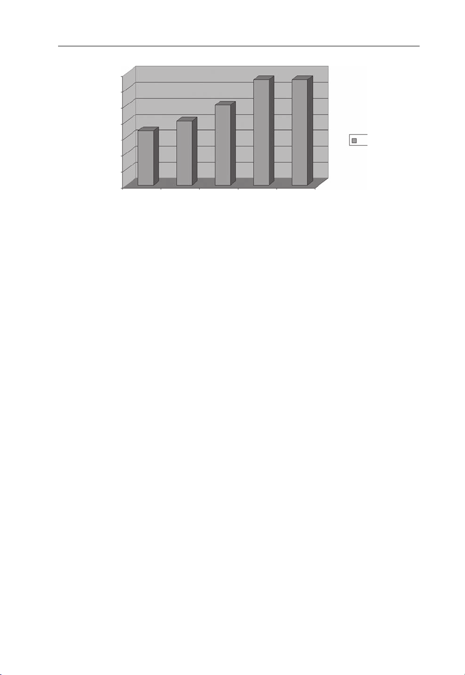
In 2006, mobile data revenue in the USA alone reached a $15.7 billion, of which 50–60%
is non-SMS revenue [6]. In some countries, mobile data revenues now accounts for
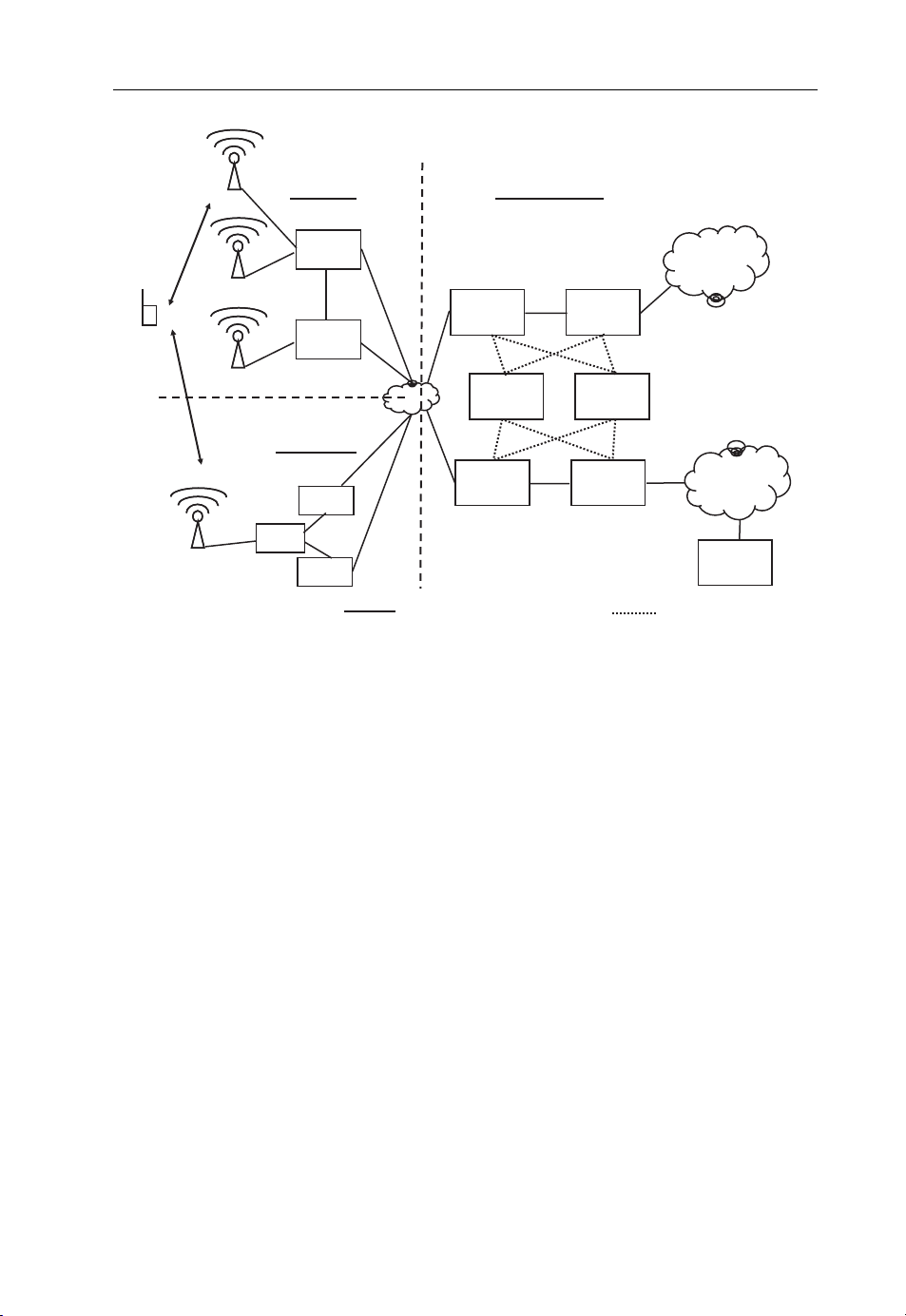
between 20 and 30% of the total operator revenue, as shown in Figure 1.1.
Page 16
Evolution from 2G over 3G to 4G 5
35
30
25
20
15
10
5
0
T-MobileUSChina
Unicom
Figure 1.1 Percentage of data revenue of mobile operators in 2007 [6].
Vodafone
Ger
O2 UK3 Italy
%
While wireless data roaming is still in its infancy, wireless Internet access via prepaid SIM
cards is already offered in many countries at similar prices to those for customers with a
monthly bill. This is another important step, as it opens the door to anytime and
anywhere Internet access for creative people such as students, who favor prepaid SIMs
to monthly bills. In addition, it makes life much easier for travelers, who until recently
had no access to the Internet while traveling, except for wireless hotspots at airports and
hotels. An updated list of such offers is maintained by the Web community on the prepaid
wireless Internet access Wiki [7].
1.5 The Future – the Need for Beyond 3G Systems
When looking into the future, the main question for network operators and vendors is
when and why Beyond 3G wireless networks will be needed. Looking back only a couple
of years, voice telephony was the first application that was mobilized. The Short Message
Service (SMS) followed some years later as the first mass market mobile data application.
By today’s standards comparably simple mobile phones were required for the service and
little bandwidth. In a way, the SMS service was a forerunner of other data services like
mobile e-mail, mobile Web browsing, mobile blogging, push-to-talk, mobile instant
messaging and many others. Such applications became feasible with the introduction
of packet-based wireless networks that could carry IP data packets and increasingly
powerful mobile devices. Today, the capacity of current 3G and 3.5G netw orks is still
sufficient for the bandwidth requirements of these applications and the number of users.
There are a number of trends, however, which are already visible and will increase
bandwidth requirements in the future:
Rising use – due to falling prices, more people will use mobile applications that require
network access.
Multimedia content – while first attempts at mobilizing the Web resulted in mostly
text-based Web pages, graphical content is now the norm rather than the exception.
Page 17

6 Beyond 3G – Bringing Networks, Terminals and the Web Together
A picture may paint a thousand words, but it also increases the amount of data that has
to be transferred for a Web page. Video and music downloads are also becoming more
popular, which further increases in bandwidth requirements.
Mobile social networks – similar to the fixed-line Internet, a different breed of
applications is changing the way people are using the Internet. In the past, users
mainly consumed content. Blogs, podcasts, picture-sharing sites and video portals
are now reshaping the Internet, as users no longer only consume content, but use the
network to share their own ideas, pictures and videos with other people. Applications
like, for example, Shozu [8] and Lifeblog [9] let users upload pictures, videos and Blog
entries from mobile devices to the Web. In particular, picture, podcast and video
transfers multiply the amount of data that users transmit and receive.
Voice over IP – the fixed line world is rapidly moving towards VoIP. It is likely that,
five years from now, many of today’s fixed line circuit-switched voice networks will
have migrated towards IP-based voice transmission. Likewise, on the network access
side, many users will use VoIP as their primary fixed line voice service, for example
over DSL or TV cable networks. The beginnings can already been observed today, as
the circuit-switched voice market is under increasing pressure due to declining subscriber numbers. As a consequence, many operators are no longer investing in this
technology. A similar trend can be observed in wireless networks. Here, however, the
migration is much slower, especially due to the higher bandwidth requirements for
transporting voice calls over a packet-switched bearer. This topic is discussed in more
detail in Chapter 1.6.
Fixed-line Internet replacement – while the number of voice minutes is increasing,
revenue is declining in both fixed line and the wireless networks due to falling prices. In
many countries, wireless operators are thus trying to keep or increase the average
revenue per user by offering Internet access for PCs, notebooks and mobile devices
over their UMTS/HSDPA or CDMA networks. Thus, they have started to compete
directly with DSL and cable operators. Again, this requires an order of magnitude of
additional bandwidth on the air interface.
Competition from alternative wireless Internet providers – in some co untries, alternative operators are already offering wireless broadband Internet access with Wi-Fi or
WiMAX/802.16 networks. Such operators directly compete with traditional UMTS
and CDMA carriers, who are also active in this market.
The broadband Internet is not a socket in the wall – this statement combines all
previous arguments and was made by Anssi Vanjoki, Executive VP of Nokia’s
Multimedia division [10], at a press conference. Today, many people already use WiFi access points to create their personal broadband Internet bubble. Thus, broadband
Internet is virtually all around them. In the future, people will not only use this bubble
with desktop computers and notebooks, but also with smaller devices such as mobile
phones with built-in Wi-Fi capabilities. Smaller devices will also change the way we
perceive this Internet bubble. No longer is it necessary to sit down at a specific place,
for example in front of a computer, in order to communicate (VoIP, e-mail, instant
messaging), to get information or to publish information to the Web (pictures, Blog
entries, videos, etc.). When the personal broadband bubble is left, mobile devices
switch over to a cellular network. As we move into the future, the cellular network
will extend into areas not covered today and available bandwidth will have to increase
Page 18

Evolution from 2G over 3G to 4G 7
to cope with the rising number of users and their connected applications. Moving
between the personal Internet bubble at home and the larger external cellular network
will become seamless as devices and services evolve.
A number of wireless technologies are currently under development or in the early
rollout phase that are designed to meet these future demands: 3GPP’s Long Term
Evolution (LTE), HSPA+ and WiMAX. In addition, Wi-Fi is also likely to be an
important network technology that is required to meet future capacity demands. All of
these technologies will be further discussed in Chapter 2. The question that arises in this
context is which of these technologies are 3G and which will be called 4G in the future?
The body responsible for categorizing wireless networks is the International
Telecommunication Union (ITU). The ITU categorizes International Mobile
Telecommunication (IMT) networks as follows:
IMT-2000 systems – this is what we know as 3G systems today, for example UMTS
and cdma2000. The list of all ITU-2000 systems is given in ITU-R M.1457-6 [11].
Enhanced IMT-2000 systems – the evolution of IMT-2000 systems, for example
HSPA, CDMA 1xEvDo and future evolutions of these systems.
IMT-Advanced systems – systems in this category are considered to be 4G systems.
At this time, there is still no clear definition of the characteristics of future IMTAdvanced (4G) systems. The ITU-R M.1645 recommendation [12] gives first hints but
leaves the door wide open:
It is predicted that potential new radio interface(s) will need to support data rates of up to
approximately 100 Mbit/s for high mobility such as mobile access and up to approximately
1 Gbit/s for low mobility such as nomadic/local wireless access, by around the year 2010 [...]
These data rate figures and the relationship to the degree of mobility [...] should be seen as
targets for research and investigation of the basic technologies necessary to implement the
framework. Future system specifications and designs will be based on the results of the research
and investigations.
When comparing current the WiMAX specifications to these potential requirements, it
becomes clear that WiMAX does not qualify as a 4G IMT-Advanced standard, since
data rates are much lower, even under ideal conditions.
3GPP’s successor to its 3G UMTS standard, known as LTE, will also have difficulties
fulfilling these requirements. Even with a four-way Multiple Input Multiple Output
(MIMO) transmission, data rates in a 20 MHz carrier would not exceed 326 Mbit/s. It
should be noted at this point that this number is already a long stretch, since putting four
antennas in a small device or on a rooftop will be far from simple in practice.
It is also interesting to compare these new systems with the evolution of current 3G
systems. The evolution of UMTS is a good example. With HSDPA and HSUPA, user
speeds now exceed the 2 Mbit/s that was initially foreseen for IMT-2000 systems. The
evolution of those systems, however, has not yet come to an end. Recent new developments in 3GPP Release 7 and 8 called HSPA+, which include MIMO technology and
other enhancements, bring ev olved UMTS technology to the same capacity and
Page 19

8 Beyond 3G – Bringing Networks, Terminals and the Web Together
bandwidth levels as currently specified for LTE on a 5 MHz carrier. HSPA+ is also
clearly not a 4G IMT-Advanced system, since it enhances a current 3G IMT-2000 radio
technology. Thus, HSPA+ is categorized as an ‘enhanced IMT-2000 system’.
To meet the likely requirements of IMT-Advanced, the WiMAX and LTE standards
bodies have started initiatives to further enhance their technologies. On the WiMAX side,
the 802.16m task group is working on standardizing an even faster radio interface. On the
LTE side, a similar working program has become known as LTE+ or Enhanced LTE.
Current research indicates that the transmission speed requirements described in
ITU-R M.1645 can only be achieved in a frequency band of 100 MHz or more. This is
quite a challenge, both from a technical point of view and also due to a lack of available
additional spectrum. Thus, it is somewhat doubtful whether these requirements will
remain in place for the final definition of 4G IMT-Advanced.
In practice, several different network technologies will coexist and evolve in the future
to meet the rising demands in terms of bandwidth and capacity. It is also likely that a
combination of different radio systems, like for example LTE together with Wireless
LAN, will be used to satisfy capacity demands.
From a user and service point of view, it does not matter if a network technology is
considered 3.5G, 3.9G or 4G. Thus, this book uses the term ‘Beyond 3G systems’ (B3G),
which includes all technologies which will be able to satisfy future capacity demands and
which either evolve out of current systems or are a new development.
1.6 All Over IP
While on the radio network side it is difficult to foresee which mix of evolved 3G and 4G
technologies will be used in the future, the future of fixed and mobile core networks is
much easier to predict. One of the main characteristics of 3G networks is the support for
circuit-switched and packet-switched services. The circuit-switched part of the core network and circuit-switched services of the radio network were specifically designed to
carry voice and video calls. Service control rests with the Mobile Switching Center
(MSC), the main component of a circuit-switched network. As subscribers can roam
freely in a mobile network, a database is required to keep track of the current location of
the subscriber in addition to the subscription information. This database is referred to as
the Home Location Register (HLR). To establish a call, a mobile phone always contacts
the MSC. The MSC then uses the destination’s telephone number to query the HLR for
the location of the destination subscriber. The call is then routed to this MSC, which in
turn informs the destination subscriber of the incoming call. This process is called
signaling. For the speech path, a transparent circuit-switched channel is established
between the two parties via the MSCs switching matrix. The signaling required for the
call is transferred over an independent signaling network, as the circuit-switched channel
only transports the speech signal.
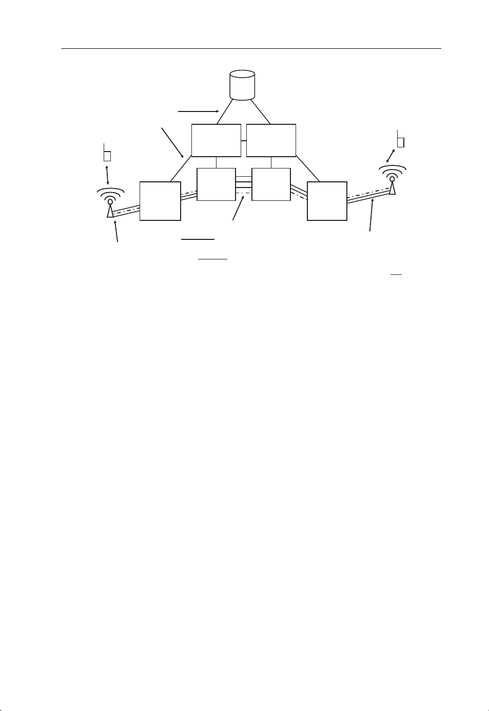
In recent network designs, MSCs are split into an MSC Call Server component that
handles the signaling and a media gateway that is responsible for forwarding the voice
call as shown in Figure 1.2. Instead of fixed connections, media gateways use packetswitched ATM (Asynchronous Transfer Mode) or IP connections to forward the call.
This removes the necessity to transport the voice data via circuit-switched connections in
the core network.
Page 20
p
Evolution from 2G over 3G to 4G 9
HLR
Location and Subscriber
Signaling
connection
Database
Call Server
Media
Radio
Network
Radio base station
Figure 1.2 Circuit switching with dedicated network components.
Gateway
Exclusive channel for
a connection or IP data flow
with constant data rate
Call Server
Media
Gateway
Radio
Network
In the radio network ATM or
A circuit switched connections
is used for a call. Voice data
and signaling for the call is not
orted over IP!
trans
While this approach is ideally suited to carry voice and video calls with a constant
bandwidth and delay requirements, it performs poorly for a connection to the Internet.
Here, all data is transported in data packets. Furthermore, data packets are not only
exchanged between two endpoints while a connection is established, but usually between
many. An example is a Web browsing session during which a user visits several Web sites,
sometimes even simultaneously. While a Web page is transferred, it is desirable to use as
much bandwidth as is currently available, rather than be limited to a circuit-switched
channel that is designed to carry a digitized narrowband voice or video stream. An
Internet connection is often also idle for a substantial duration. During this time,
resources are best given to other users. This is also not possible with a circuit-switched
connection, because it is an exclusive channel that offers a fixed amount of bandwidth
between two parties while it is established.
For these reasons, 3G networks contain a separate core network to forward data
packets rather than circuits. This is shown in Figure 1.3. The radio network serves both
the circuit-switched and the packet-switched network and the kind of connection established to a user over the air depends on whether a circuit-switched connection or a packetswitched connection is required. Some systems such as UMTS even allow devices to
simultaneously use packet and circuit connections so a phone call can be made while
being connected to the Internet and transferring data.
Traditional fixed line networks use a similar split for simultaneous voice telephony and
Internet access. Since DSL became popular, analog voice service and DSL use the same
physical line to the customer’s home. A splitter is then used to separat e the analog
telephone signal from the DSL service as they operate in different frequency bands. In
the central exchange office, a similar splitter is used to connect the line of the subscriber to
Page 21
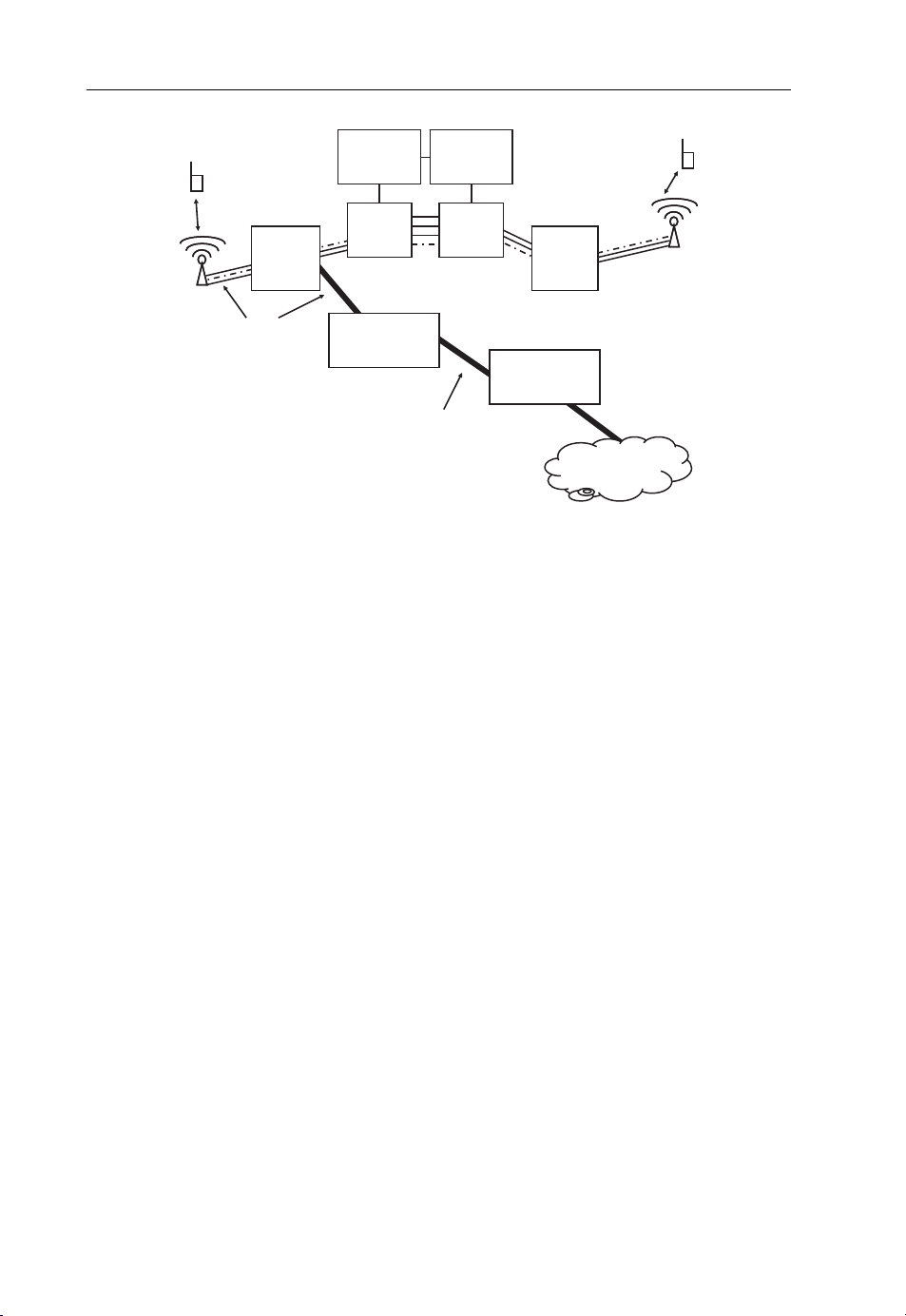
10 Beyond 3G – Bringing Networks, Terminals and the Web Together
Call Server
Media
Radio
Network
ATM or IP
Figure 1.3 Typical circuit-switched and packet-switched dual architecture of 3G networks. The
location and subscriber database is not shown.
Gateway
Radio Network
Packet Gateway
Call Server
Media
Gateway
Private
IP Network
Radio
Network
Internet
Gateway
Internet
the local circuit-switched exchange for voice calls and additionally to a DSL Access
Multiplexer (DSLAM) for Internet connectivity. Telephone exchanges are then interconnected via circuit-switched connections, while the DSLAM connects to a packetswitched backbone. In the meantime, however, there is a clear shift to transporting
telephone calls over the Internet connection as well. Instead of connecting the analog
phone to the splitter, the DSL access device is equipped with a jack for the phone. The
DSL access device digitizes the voice signal and sends it as IP packets over the DSL
connection. In many cases, an IP-based SIP server and RTP (Real Time Transport
Protocol) replace the local circuit-switched telephone exchange. There are several advantages of this approach:
Only a single type of core network is needed, as the circuit-switched telephone
exchanges and the circuit-switched network between them are no longer
necessary.
Using an IP network for voice calls makes it a lot easier for companies other than the
local telephone carrier to offer telephony services, as the controlling network element
no longer needs to be at the local exchange.
Voice services can be combined with other services. Since there is more bandwidth
available, users can, for example, exchange pictures with each other while being
engaged in a voice call or add video at any point during the conversation.
While the trend to VoIP is already fully underway in fixed-line networks, wireless networks have not yet caught up. Here, things are moving more slowly for a number of
reasons. The main reason is that 3G mobile networks did not have the necessary
bandwidth to support VoIP, which requires a higher data rate than circuit-switched
Page 22

Evolution from 2G over 3G to 4G 11
voice calls. The gap has been somewhat reduced by the introduction of 3.5G networks.
However, only B3G networks (evolved IMT-2000 and IMT-Advan ced) will have enough
capacity and an optimized radio network to support VoIP on a large scale.
The challenges are significant, but none of the new B3G network architectures discussed
in Chapter 2 have a circuit-switched core network. To be successful, it is essential for B3G
wireless network operators to have a fully functioning VoIP solution in place in the future
that is able to seamlesslytransfer the call to a circuit-switched wireless connection when the
user roams out of network coverage. This is discussed in more detail in Chapter 4.
1.7 Summary
This chapter presented how fixed and wireless networks evolved in the past 15 years from
circuit-switched voice-centric systems to packet-switched Internet access systems. Due to
the additional complexity of wireless systems, enhancements are usuall y introduced in
fixed-line systems first and only some years later in wireless systems as well. To date,
fixed-line networks offer data rates to the customer premises of several megabits per
second, in some cases already going beyond this. Wireless 3.5G networks are capable of
data rates in the order of several megabits per second. In the future, more bandwidth and
capacity will be achieved by evolving current wireless network technologies (evolved
IMT-2000) and by designing new access networks (IMT-Advanced). This book therefore
not only c oncentrates on 4G systems, but also discusses the evolution of 3G systems.
Another important development is the use of packet-switched networks for transporting
telephone calls, which is referred to as VoIP. This trend is already fully underway in fixedline networks and will inevitably also happen in B3G networks, as systems such as
WiMAX and LTE have been designed without a circuit-switched core network dedicated
to voice calls.
References
1. Background on Fidonet (2008) http://www.fidonet.org.
2. Neuhetzki, T. (December 2005) German long distance tariffs in the 1990s, http://www.teltarif.de/arch/
2005/kw52/s19950.html.
3. Sauter, M. (August 2006) 1000 new mobile phone users a minute, http://mobilesociety.typepad.com/
mobile_life/2006/08/1000_new_mobile.html.
4. Andersen, T. (19 February 2007) Mobile phone lifeline for world’s poor, http://news.bbc.co.uk/1/hi/
business/6339671.stm.
5. 2G and 3G coverage maps (2008) http://www.coveragemaps.com.
6. Sharma, C. (September 2007) Global wireless data market, http://www.chetansharma.com/
globalmarketupdate1H07.htm.
7. The prepaid wireless Internet access Wiki (2008) http://prepaid-wireless-internet-access.wetpaint.com.
8. Shozu (2008) http://www.shozu.com.
9. Lifeblog (2008) http://r2. nokia.com/nokia/0,71739,00.html.
10. Biography of Anssi Vanjoki Executive VP of Nokia Multimedia (2008) http://www.nokia.com/A4126347.
11. The International Telecommunication Union (2006) Detailed specifications of the radio interfaces of
International Mobile Telecommunications-2000 (IMT-2000), ITU-R M.1457-6.
12. The International Telecommunication Union (2003) Framework and overall objectives of the future
development of IMT-2000 and systems beyond IMT-2000, ITU-R M.1645.
Page 23

2
Beyond 3G Network
Architectures
2.1 Overview
As discussed in Chapter 1, the general trend in telecommunications is to move all
applications to a common transmission protocol, the Internet Protocol. The tremendous
advantage of this approach is that applications no longer require a specific network
technology but can be used over different kinds of networks. This is important since,
depending on the situation, an application might be used best over a cellular network
while at other times it is more convenient and cheaper to use a wireless home or office
networking technology such as Wi-Fi. The increasing number of multiradio devices
supports this trend. Today and even more so in the future, a number of wireless
technologies are deployed in parallel. This is necessary as the deployment of a new
network requires a considerable amount of time and there are usually only a small
number of devices supporting a new network technology at first. It is therefore important
that different network technologies are deployed not only in parallel but also at the same
location. As well as the introduction of new technologies, existing network technologies
continue to evolve to offer improved performance while the new technology is not yet
deployed or is just in the process of being rolled out. For these reasons, this chapter looks
at a number of different Beyond 3G network technologies with an emphasis on those
with the highest market share. In this context, the term ‘Beyond 3G networks’ is used for
cellular networks that offer higher speeds than the original UMTS networks with their
maximum data rate of 384 kbit/s per user.
In the cellular world, the Universal Mobile Telecommunication System (UMTS) with
its High-speed Packet Access (HSPA) evolution is currently the Beyond 3G system with
the broadest deployment. This system, together with its future evolution, HSPAþ,is
therefore discussed first.
Next, the chapter focuses on the successor technology of HSPA and HSPAþ, which is
commonly known as Long Term Evolution (LTE). In the standa rds, LTE is referred to as
Beyond3G–BringingNetworks,TerminalsandtheWebTogether:LTE, WiMAX, IMS, 4G Devices and the Mobile Web 2.0
MartinSauter © 2009JohnWiley&Sons,Ltd. ISBN: 978-0-470-75188-6
Page 24

14 Beyond 3G – Bringing Networks, Terminals and the Web Together
the Evolved Packet System (EPS), which is divided into the Evolved Packet Core (EPC)
and the Enhanced-UMTS Terrestrial Radio Access Network (E-UTRAN).
While LTE mainly addresses incumbent wireless operators, there is also great interest
from new companies in building wireless networks for Internet access. Many of these
companies are attracted by the Worldwide Interoperability for Microwave Access
(WiMAX) standard, in particular with the 802.16e air interface. WiMAX is very similar
to LTE, but designed from the ground up without the need for backwards-compatibili ty.
Therefore, it is much more suitable for these companies’ needs. Since it is expected that
both LTE and WiMAX will gain considerable market share, both technologies are
discussed to show the similarities and also the differences between the two.
As will be shown throughout this book, 802.11 Wi-Fi networks will play an important
role in overall wireless network architectures of the future. Consequently, this chapter
also introduces Wi-Fi and the latest enhancements built around the original standard,
such as an evolved air interface with speeds of up to 600 Mbit/s, security enhancements
for home and enterprise use and quality of service extensions.
To give an initial idea about the performance of each system, some general observations for each system in terms of bandwidth, speed and latency are discussed. Since these
parameters are of great importance, and often grossly exaggerated by marketing departments, Chapter 3 will then look at this topic in much more detail.
2.2 UMTS, HSPA and HSPAþ
2.2.1 Introduction
Initial drafts of UMTS standards documents appeared in working groups of the Third
Generation Partnership Project (3GPP) at the end of 1999, but work on feasibility studies
for the system began much earlier. A few UMTS networks were opened to the public in
2003, but it was not until the end of 2004, when adequate UMTS mobile phones became
available and networks were rolled out to more than just a few cities, that even early
adopters could afford and actually use UMTS. A time frame of five years from a first set
of specifications to first deployments is not uncommon due to the complexity involved.
This should also be considered when looking at emerging network technologies such as
LTE and WiMAX, which are currently in this window between standardization and
deployment.
2.2.2 Network Architecture
Figure 2.1 shows an overview of the network architecture of a UMTS network. The
upper-left side of the figure shows the radio access part of the network, referred to in the
3GPP standards as the UMTS Terrestrial Radio Access Network (UTRAN).
2.2.2.1 The Base Stations
The UTRAN consists of two components. At the edge of the network, base stations,
referred to in the standards as the NodeB, communicate with mobile devices over the air.
In cities, a base station usually covers an area with a radius of about 1 km, sometimes
Page 25
g
g
Beyond 3G Network Architectures 15
UE
UTRAN
RNC
NodeB
RNC
NodeB
Core Network
MSC GMSC
HLR
SCP
PSTN
GSM BSS
TRAUTRAU
BSCBSC
BTS
Figure 2.1 Common GSM/UMTS network. (Reproduced from Communication Systems for the
Mobile Information Society, Martin Sauter, 2006, John Wiley and Sons.)
PCUPCU
Data and signalin
SGSN
GGSN
Internet
Server
Signalin
less, depending on the population density and bandwidth requirements. To increase the
amount of data and the number of simultaneous voice calls per base station, the coverage
area is usually split into two or three sectors. Each sector has its own directional antenna
and transceiver equipment. In the standards, a sector is sometimes also referred to as a
cell. A NodeB with three sectors therefore consists of three individual cells. If a user
walked around such a base station during an ongoing voice call or while data was
exchanged, he would be consecutively served by each of the cells. During that time, the
radio network would hand the connection over from one cell to the next once radio
conditions deteriorated. From a technical point of view, there is thus little difference
between a handover between cells of the same base station and between cells of different
base stations. These and other mobility management scenarios will be discussed in more
detail in Section 2.2.3. The radio link between mobile devices and the base station is also
referred to as the ‘air interface’ and this term will also be used throughout this book.
A device using a UMTS network is referred to in the standard as User Equipment (UE).
In this book, however, the somewhat less technical terms ‘mobile’, ‘mobile device’ and
‘connected mobile device’ are used instead.
Today, base stations are connected to the network via one or more 2 Mbit/s links,
referred to as E-1 connections in Europe and T-1 connections in the USA (with a slightly
lower transmission speed). Each E-1 or T-1 link is carried over a pair of copper cables.
An alternative to copper cables is a microwave connection, which can carry several
Page 26

16 Beyond 3G – Bringing Networks, Terminals and the Web Together
logical E-1 links over a single microwave connection. This is preferred by many operators
as they do not have to pay monthly line rental fees to the owner of the copper cable
infrastructure. To make full use of the air interface capacity of a multisector base station,
several E-1 links are required. The protocol used over these links is ATM (Asynchronous
Transfer Mode), a robust transmission technology widely used in many fixed and
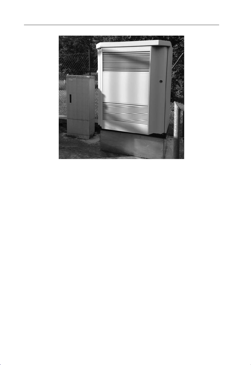
wireless telecommunication networks around the world today. Figure 2.2 shows a typical
base station cabinet located at street level. In practice, base stations are also frequently
installed on flat rooftops close to the antennas, as there is often no space at ground level
and as this significantly reduces the length and thus the cost for the cabling between the
base station cabinet and the antennas.
As technology evolves, using E-1 links over copper cables becomes more difficult
since the number of copper cables leading to a base station is limited and, more
significantly, the line rental costs per month are high. Network operators have therefore
begun using a number of alternative transmission technologies to connect base stations
to the network:
High bandwidth microwave links – a single microwave link can be used to carry
several logical E-1 connections. The latest equipment is capable of speeds exceeding
50 Mbit/s [1].
Fiber links – especially in dense urban areas, many fixed line carriers are currently
deploying additional fiber cables for providing very high data rate Internet access to
businesses and homes. This infrastructure is also ideal for connecting base stations to
the rest of the infrastructure of a wireless network. In practice, however, only a fraction
of deployed base stations already have a fiber laid up to the cabinet.
ADSL/VDSL – a viable alternative to directly using fiber is to connect base stations via
a high-speed VDSL link to an optical transmission network. T-Mobile in Germany is
one operator that has chosen this solution [2]. In some cases, base stations still require
at least one E-1 link for synchronizing the base station with the rest of the network and
for carrying voice calls.
Ethernet – a transmission protocol becoming very popular today in radio access
networks is IP over Ethernet. This is reflected in new designs for UMTS/HSPA base
stations, which can be equipped with E-1 ATM-based interfaces or alternatively via IP
over Ethernet. The Ethernet interface is either based on the standard 100 Mbit/s
100Base-TX twisted pair copper cable interface commonly used with other IT equip-
ment such as PCs and notebooks or via an optical port. In the case of copper cabling,
additional equipment is usually required to transport the Ethernet frames over longer
distances, as 100Base-TX limits cable length to 100 m.
As the technology used for backhauling data from base stations has a significant impact
on the bandwidth and cost of a network, this topic will be discussed in more detail in
Section 3.17.
2.2.2.2 The Radio Network Controllers
The second component of the radio access network is the Radio Network Controller
(RNC). It is responsible for the following management and control tasks:
Page 27

Beyond 3G Network Architectures 17
The establishment of a radio connection, also referred to as bearer establishment.
The selection of bearer properties such as the maximum bandwidth, based on current
available radio capacity, type of required bearer (voice or data), quality of service
requirements and subscription options of the user.
Mobility management while a radio bearer is established, that is, handover control
between different cells and different base stations of a network.
Overload control in the network and on the radio interface. In situations when more
users want to communicate than there are resources available, the RNC can block new
connection establishment requests to prevent other connections from breaking up.
Another option is to reduce the bandwidth of established bearers. A new data connection might, for example, be blocked by the network if the load in a cell is already at
the limit, while for a new voice call, the bandwidth of an ongoing data connection
might be reduced to allow the voice call to be established. In practice, blocking the
establishment of a radio bearer for data transmission is very rare, as most network
operators monitor the use of their networks and remove bottlenecks, for example by
installing additional transceivers in a base station, by increasing backhaul capacity
between the base station and the RNC or by installing additional base stations to
reduce the coverage area and thus the number of users per base station. Capacity
management will be discussed in more detail in Chapter 3.
2.2.2.3 The Mobile Switching Center
Moving further to the right in Figure 2.1, it can be seen that the RNCs of the network are
connected to gateway nodes between the radio access network and the core network.
In UMTS, there are two independent core network entities. The upper right of the figure
shows the MSC, which is the central unit of the circuit-switched core network. It handles
voice and video calls and forwards SMS messages via the radio network to subscribers.
As discussed in Chapter 1, circuit switching means that a dedicated connection is
established for a call between two parties via the MSC that remains in place while the
call is ongoing. Large mobile networks usually have several MSCs, each responsible for a
different geographical area. All RNCs located in this area are then connected to the
MSC. Each MSC in the network is responsible for the management of all users of the
network in its region and for the establishment of circuit-switched channels for incoming
and outgoing calls. When a mobile device requests the establishment of a voice call, the
RNC forwards the request to the MSC. The MSC then checks if the user is allowed to
make an outgoing call and instructs the RNC to establish a suitable radio bearer. At the
same time, it informs the called party of the call establishm ent request or, if the called
party is located in a different area or different network, establishes a circuit-switched
connection to another MSC. If the subscriber is in the same network it might be possible
to contact the MSC responsible for the called party directly. In many cases, however, the
called party is not in the same network or not a mobile subscriber at all. In this case, a
circuit-switched connection is established to a Gateway MSC (GMSC), shown in
Figure 2.1 on the top right. Based on the telephone number of the called party, the
GMSC then forwards the call to an external fixed or mobile telephone network.
In practice, a MSC usually serves mobile subscribers and also acts as a GMSC.
Page 28

18 Beyond 3G – Bringing Networks, Terminals and the Web Together
To allow the MSC to manage subscribers and to alert them about incoming calls,
mobile devices need to register with the MSC when they are switched on. At the beginning of the registration process, the mobile device sends its International Mobile
Subscriber Identity (IMSI), which is stored on a SIM card, to the MSC. If the IMSI is
not known to the MSC’s Visitor Location Register (VLR) database from a previous
registration request, the network’s main user database, the Home Location Register, is
queried for the user’s subscription record and authentication information. The authentication information is used to verify the validity of the request and to establish an
encrypted connection for the exchange of signaling messages. The authentication information is also used later on during the establishment of a voice or video call to encrypt the
speech path of the connection. Note that the exchange of these messages is not based on
the IP protocol but on an out-of-band signaling protocol stack called Signaling System
Number 7 (SS7). Out-of-band means that messages are exchanged in de dicated signaling
connections, which are not used for transporting circuit-switched voice and video.
2.2.2.4 The SIM card
An important component of UMTS networks, even though it is very small, is the
Subscriber Identity Module, the SIM card. It allows the network subscription to be
separate from the mobile device. A user can thus buy the SIM card and the mobile device
separately. It is therefore possible to use the SIM card with several devices or to use several
SIM cards with a single device. This encourages competition between network operators,
as users can change from one network to another quickly if prices are no longer competitive. When traveling abroad, it is also possible to buy and use a local prepaid SIM card to
avoid prohibitive roaming charges. Separating network subscriptions from mobile devices
has the additional benefit that mobile devices can not only be bought from a network
operator but also from independent shops, for example electronic stores and mobile phone
shops that sell subscriptions for several network operators. This stimulates competitive
pricing for mobile devices, which would not happen if a device could only be bought from a
single source. A further discussion of this topic can be found in [3].
2.2.2.5 The SMSC
A data service that became very popular long before the rise of current high-speed
wireless Internet access technologies is the short message service, used to send text
messages between users. As the service dates back to the mid 1990s, it is part of the
circuit-switched core network. SMS messages are transported in a store and forward
fashion. When a subscriber sends a message, it is sent via the signaling channel, the main
purpose of which is to transport messages for call establishment and mobility management purposes, to the Short Message Service Center (SMSC). The SMSC stores the
message and queries the Home Location Register database to find the MSC which is
currently responsible for the destination subscriber. Afterwards, it forwards the message,
again in an SS-7 signaling link, to the mobile switching center. When receiving the text
message, the MSC locates the subscriber by sending a paging message. This is necessary,
as in most cases the subscriber is not active when a text message arrives and therefore the
Page 29

Beyond 3G Network Architectures 19
user’s current serving cell is not known to the MSC. On the air interface, the paging
message is sent on a broadcast channel that is observed by all devices attached to the
network. The mobile device can thus receive the paging message and send an answer to
the network despite not having being in active communication with the network. The
network then authenticates the subscriber, activates encryption and delivers the text
message. In case the subscriber is not reachable, the delivery attempt fails and the
SMSC stores the message until the subscriber is reachable again.
2.2.2.6 Service Control Points
Optional, but very important, components in circuit-switched core networks are integrated databases and control logic on Service Control Points (SCPs). An SCP is required,
for example, to offer prepaid voice services that allow users to top-up an account with a
voucher and then use the credit to make phone calls and send SMS messages. For each
call or SMS, the MSC requests permission from the prepaid service logic on an SCP. The
SCP then checks and modifies the balance on the user’s account and allows or denies the
request. Mobile switching centers communi cate with SCPs via SS-7 connections. When a
prepaid user roams to another country, foreign MSCs also need to communicate with the
SCP in the home network of the user. As there are many MSC vendors, the interacti on
model and protocol between MSCs and SCPs have been specified in the CAMEL
(Customized Applications for Mobile Enhanced Logic) standard [4].
For providing the actual service (e.g. prepaid), only signaling connections between
SCPs and MSCs are required. Some services, such as prepaid, however, also require an
interface to allow a user to check his balance and to top up their account. In practice there
are several possibilities. Most operators use some form of scratch card and an automated
voice system for this purpose. Therefore, there are usually also voice circuits required
between SCP-controlled interactive voice gateways and the MSCs. In addition, most
prepaid services also let users top up or check their current balance via short codes
(e.g. *100#), which do not require the establishment of a voice call. Instead, such short
codes are sent to the SCP via an SS-7 signaling link.
2.2.2.7 Billing
In addition to the billing of prepaid users, which is performed in real time on SCPs,
further equipment is required in the core network to collect billing information from the
MSCs for subscribers who receive a monthly invoice. This is the task of billing servers,
which are not shown in Figure 2.2. In essence, the billing server collects Call Detail
Records (CDRs) from the MSCs and SMSCs in the network and assembles a monthly
invoice for each user based on the selected tariff. Call detail records contain information
such as the identity of the calling party, the identity of the called party, date and duration
of the call and the identity of the cell from which the call was originated. Location
information is required as calls placed from foreign networks while the user is roaming
are charged differently from calls originated in the home network. Some network
operators also use location information for zone-based billing, that is, they offer cheaper
calls to users while they are at home or in the office. Another popular billing approach is
Page 30
20 Beyond 3G – Bringing Networks, Terminals and the Web Together
Figure 2.2 A typical GSM or UMTS base station cabinet.
to offer cheaper rates at certain times. Most operators combine many different options
into a single tariff and continuously change their billing options. This requires a flexible
rule-based billing service.
2.2.2.8 The Packet-switched Core Network
The core network components discussed so far have been designed for circuit-switched
communication. For communicating with services on the Internet, which is based on
packet switching, a different approach is required. This is why a packet-switched core
network was added to the circuit-switched core network infrastructure. As can be seen in
Figure 2.2, the Radio Network Controller connects to both the circuit-switched core
network and the packet-switched core network. UMTS devices are even capable of having
circuit-switched and packet-switched connections established at the same time. A user can
therefore establish a voice call while at the same time using his device as a modem for a PC,
or for downloading content such as a podcast to the mobile device without interrupting the
connection to the Internet while the voice call is ongoing. Another example of the benefits
of being connected to both the packet-switched and circuit-switched networks is that an
ongoing instant messaging session is not interrupted during a voice call.
Before a mobile device can exchange data with an external packet-switched network
such as the Internet, it has to perform two tasks. First, the mobile device needs to attach
to the packet-switched core network and perform an authentication procedure. This is
Page 31

Beyond 3G Network Architectures 21
usually done after the device is switched on and once it has registered with the circuitswitched core network. In a second step, the mobile device can then immediately, or at
any time later on, request an IP address from the packet-switched side of the network.
This process is referred to as establishing a data call or as establishing a PDP (Packet
Data Protocol) context. The expression ‘establishing a data call’ is interesting because it
suggests that establishing a connection to the Internet or another external packet network is similar to setting up a voice call. From a signal ing point of view, the two actions
are indeed similar. The connections that are established as a result of the two requests,
however, are very different. While voice calls require a connection with a constant
bandwidth and delay that remain in place while the call is ongoing, data calls only require
a physical connection while packets are transmitted. During times in which no data is
transferred, the channel for the connection is either modified or completely released.
Nevertheless, the logical connection of the data call remains in place so the data transfer
can be resumed at any time. Furthermore, the IP address remains in place even though no
resources are assigned on the air interface. In UMTS, separating the attachment to the
packet-switched core network from the establishment of a data connection makes sense
when looked at from a historical and practical perspective. The majority of mobile
devices today are mostly used for voice communication for which no Internet connection
is required. Therefore, the mobile device can perform its main duty without establishing a
data call. All other networks that will be discussed in this chapter, however, are only
based on a packet-switched core network which is also used for voice calls. As a result,
attaching to the network and requesting an IP address is part of the same procedure and
the notion of a ‘data call’ is no longer part of the system design.
2.2.2.9 The Serving GPRS Support Node
The packet-switched UMTS core network was, like the circuit-switched core network,
adapted from GSM with only a few modifications. This is the reason why the gateway
node to the radio access network is still referred to as the Serving GPRS Support Node
(SGSN). GPRS stands for General Packet Radio Service and is the original name of the
packet-switched service introduced in GSM networks. Like the MSC, the SGSN is
responsible for subscriber and mobility management. To enable users to move between
the coverage areas of different RNCs, the SGSN keeps track of the location of users and
changes the route of IP packets arriving from the core network when they change their
locations. SGSNs are connected to RNCs via ATM links. Since RNCs often control
several hundred cells and are physically distant from an SGSN, optical connections are
used. In practice, a single RNC is connected to an SGSN via one or more OC-3 optical
links with a speed of 155 Mbit/s each or an OC-12 optical connection with a speed of 622
Mbit/s [5]. Above the ATM layer, IP is used as a transport protocol.
The SGSN also has a signaling connection to the Home Location Register of the
network that in addition to the data required for the circuit-switched network also
contains subscription information for the packet-switched network. This includes, for
example, if the user is allowed to use packet-switched services, their quality of service
settings such as the maximum transmission speed that is granted by the network and
which access points to the Internet they are allowed to use. The record also shows
Page 32

22 Beyond 3G – Bringing Networks, Terminals and the Web Together
whether a user has a prepaid contract, in which case the SGSN has to contact a prepaid
SCP before a connection request is granted.
2.2.2.10 The Gateway GPRS Support Node
At the edge of the wireless core network, Gateway GPRS Support Nodes (GGSNs)
connect the wireless network to the Internet. Their prime purpose is to hide the mobility
of the users from routers on the Internet. This is required as IP routers forward packets
based on the destination IP address and a routing table. For each incoming packet, each
router on the Internet consults its routing table and forwards the packet to the next router
via the output port specified in the routing table. Eventually, the packets for wireless
subscribers end up at the GGSN. Here, the routing mechanism is different. As RNCs and
SGSNs can change at any time due to the mobility of the subscriber, a static database
containing the next hop based on the IP address is not suitable. Instead, the GGSN has a
database table which lists the IP address of the SGSN currently responsible for a subscriber with a certain IP address. The IP packet for the subscriber is then enclosed in an IP
packet with the destination address of the SGSN. This principle is called tunneling because
each IP packet to the subscriber is encapsulated in an IP packet to the responsible SGSN.
On the SGSN the original IP packet is restored and once again tunneled to the RNC.
Figure 2.3 shows how tunneling an IP packet in the core network works in practice.
The protocol stack shown uses the Ethernet protocol on layer 2 which is followed by IP
on layer 3. The source and destination address of the IP packet belong to the SGSN and
GGSN of the netwo rk. Afterwards, the GPRS Tunneling Protocol (GTP) encapsulates
the original IP packet. Here, the source and destination address represent the subscriber
and a host on the Internet such as a Web server.
In addition to tunneling, the GGSN is also responsible for assigning IP addresses to
subscribers. During the connection establishment, the SGSN verifies the request of the
subscriber with the information from the HLR and then requests the establishment of a
Figure 2.3 Encapsulated IP packet in a packet-switched core network.
Page 33

Beyond 3G Network Architectures 23
tunnel and an assignment of an IP address from the GGSN. The GGSN then assigns an
IP address from a pool and establishes the tunnel. In practice, there are two types of IP
addresses. Many network operators use private IP addresses that are not valid outside the
network. This is similar to the use of private IP addresses in home networks where the
DSL or cable router assigns private IP addresses to all devices in the home network. To
the outside world, the network is represented with only a single IP address and the DSL
or cable router has to translate internal addresses in combination with TCP and UDP
port numbers into the external IP address with new TCP and UDP port numbers. This
process is referred to as Network Address Translation (NAT). If private IP addresses are
used in wireless networks, the same process has to be performed by the GGSN. The
advantage for the operator is that fewer public IP addresses are required, of which there is
a shortage today. Other operators use public IP addresses for their subscribers by default.
For subscribers this has the advantage that they are directly reachable from the Internet,
which is required for applications such as hosting a Web server or for remote desktop
applications. It should be noted, howeve r, that a public IP address also has disadvantages, especially for mobile devices, as unsolicited packets arriving from the Internet can
drain batteries of mobile devices [6]. In practice, a subscriber can have several connection
profiles, referred to as Access Point Names (APNs). The operator can therefore choose
which subscribers and applications to use private or public IP addresses for.
2.2.2.11 Interworking with GSM
The lower left side of Figure 2.2 shows a GSM radio network, which is also connected to
the circuit-switched and packet-switched core network. Depending on the network
vendor, the GSM radio network can either be connected to the same MSCs and
SGSNs or to separate ones. This is possible since the functionality of these components
is very similar for GSM and UMTS. The interfaces to the 2G and 3G radio networks,
however, are different. For the conn ections to the 3G radio network, ATM is used as the
lower layer transport protocol while the connection between the SGSN and the 2G radio
network is based on the Frame Relay protocol. In a newer version of the standard, an
IP-based interface between SGSNs and the 2G radio network has been specified as well.
At this point, however, it is not widely used. The MSC is connected to the GSM radio
network via circuit-switched links.
2.2.3 Air Interface and Radio Network
2.2.3.1 The CDMA Principle
2G radio systems such as GSM are based on timeslots and channels on different carrier
frequencies so a single base station can serve many users simultaneously. While such an
approach is well suited for the transmission of circuit-switched voice calls, it only offers
limited flexibility for packet-switched data transmission, as the GSM channel bandwidth
is only 200 kHz and thus only a limited amount of bandwidth can be assigned to a single
user at a time. For 3G systems such as UMTS, it was therefore decided to use a different
transmission scheme for the air interface. An alternative transmission technology that
overcomes the limitations of a narrow band and was already well understood at the end
Page 34

24 Beyond 3G – Bringing Networks, Terminals and the Web Together
of the 1990s, when work on UMTS started, was Code Division Multiple Access
(CDMA). Instead of a narrow channel bandwidth of 200 kHz as in GSM, the
Wideband CDMA (W-CDMA) channel used in UMTS has a bandwidth of 5 MHz.
Furthermore, instead of assigning timeslots, all users communicate with the base station
at the same time but using a different code. These codes are also referred to as spreading
codes, as a single bit is represented on the air interface by a codeword. Each binary unit of
the codeword is referred to as a chip to clearly distinguish it from a bit. For a transmission
speed of 384 kbit/s, a single bit is encoded in eight chips. The length of the spreading code
thus equals 8. The codes used by different users for transmitting simultaneously are
mathematically orthogonal to each other. The base station can separate several simultaneous transmissions from mobile devices by applying the reverse algorithm to the one
used by the mobile devices, as shown in Figure 2.4, and by knowing the codes used by
each mobile device.
Figure 2.4 Simultaneous data streams of two users to a single base station. (Reproduced from
Communication Systems for the Mobile Information Society, Martin Sauter, 2006, John Wiley
and Sons.)
To accommodate the different bandwidth requirements of different users, the system
can use several different spreading code lengths simultaneously. For voice calls, which
require a transmission rate of only 12.2 kbit/s, a spreading code length of 128 is used. This
means that each bit is represented on the air interface by 128 chips and that up to 128
users can send their data streams simultaneously under ideal conditions. In practice, the
number of voice calls per cell is smaller, due to interference from neighboring cells and
transmission errors due to nonideal signal conditions. This requires a higher signal-tonoise ratio than could be achieved if there were 128 simultaneous transmissions.
Furthermore, some of the codes are reserved for broadcasting system information
channels to all devices in the cell, as will be discussed in more detail below. In practice,
it is estimated in [7] that each UMTS cell can host up to 60 simultaneous voice calls,
excluding subscribers using the cell for packet-switched Internet access.
Page 35

Beyond 3G Network Architectures 25
To increase the data rate of UMTS beyond 384 kbit/s, HSPA and HSPAþ introduce,
among other enhancements, the simultaneous use of more than one spreading code per
mobile device. This is discussed in more detail below.
2.2.3.2 UMTS Channel Structure
In wired Ethernet networks, which are commonly used in home and business environments today, detecting the network and sending packets is stra ightforward for devices.
As soon as the network cable is plugged in, the network card senses the transmission of
packets over the cable and can start transmitting as well, as soon as it detects that no
other device is sending a packet. In wireless networks, however, things are more complicated. First of all, there are usually several networks visible at the same time so the device
needs to get information about which network belongs to which operator. Also, devices
need to detect neighboring cells to be able to quickly react to changing signal levels when
the user moves. As keeping the receiver switched on at all times is not very powerefficient, it is also necessary to have a mechanism in place that allows the device to
power down the radio in situations where little or no data is transmitted and only wake
up periodically to check for new data. Especially for voice calls, it is furthermore
important to ensure a certain quality of service in order to prevent the network from
breaking down in overload situations. For these reasons, the radio channel is split up into
a number of individual channels. Access to these channels is controlled by the network
and can be denied during overload situations.
In UMTS networks, a physical channel is represented by a certain spreading code. The
following list gives an overview of the most important channels in the downlink direction
(network to mobile device) and the uplink direction (mobile device to the network). All of
these channels are transmitted simultaneously:
The Primary Common Control Physical Channel (P-CCPCH) – this channel carries
the logical broadcast control channel which is monitored by all mobile devices while
they do not have an active connection established to the network. Information dis-
tributed via this channel includes the identity of the cell, how the network can be
accessed, which spreading codes are used for other channels in the cell, which codes are
used by neighboring cells, timers for network access, and so on.
The Secondary Common Control Physical Channel (S-CCPCH) – this physical chan-
nel serves several purposes and thus carries a number of different logical channels.
First, it carries paging messages that are used by the network to search for mobile
devices for incoming calls, SMS messages or when data packets arrive after a long
period of inactivity. The channel is also used to deliver IP packets and control messages
to devices which only exchange small quantities of data at a particular time and thus do
not need to be put into a more active state.
Physical Random Access Channel (PRACH) – the random access channel only exists
in the uplink direction and is the only channel that a mobile device is allowed to
transmit without prior permission of the network. Its purpose is to allow the mobile to
request the establishment of a connection to set up a voice call, to establish a data call,
to react to a paging message or to send an SMS message. If a data call is already
Page 36

26 Beyond 3G – Bringing Networks, Terminals and the Web Together
established and the mobile only sends or receives a small amount of data, the channel
can also be used to send IP packets in combination with the S-CCPCH in the downlink
direction. However, the data rate in both directions is very low and round trip delay
times are high (in the order of 200 ms). The network therefore usually assigns different
channels that are dedicated to packet-switched data transfers as soon as it detects
renewed network ac tivity from a device.
Dedicated Physical Data and Control Channels (DPDCH, DPCCH) – once a mobile
has contacted the network via the random access channel, the network usually decides
to establish a full connection to the mobile. In case of a voice call, the network assigns a
dedicated connection. On the air interface, the connection uses a dedicated spreading
code that is assigned by the network. In the early days, UMT S networks also used
dedicated connections for packet-switched data transmissions. In practice, however,
the speed of such dedicated connections was limited to 384 kbit/s. Only a few users
could get such a connection, also referred to as a bearer, in a cell simultaneously.
Another downside of using a dedicated bearer for packet-switched connections is that
the network has to frequently reassign spreading codes to different users. This is
necessary, as most packet-switched data transmissions are bursty in nature and therefore only require a high bandwidth bearer for a limited amount of time. In order to
reuse the spreading code for oth er users, the network needs to change the spreading
code length of a connection as soon as it is not fully used any more or even put the
connection on a common control channel in order to have the resources available for
other users. In practice, this creates a high signaling overhead and a mediocre user
experience. It was thus decided that a new concept was needed that offers higher data
rates and more flexibility for bursty data transmissions. The outcome of this process is
known today as High-speed Packet Access, which many people also refer to as 3.5G.
HSPA will be discussed in Section 2.2.4.
2.2.3.3 Radio Resource Control States
To save power and to only assign resources to mobile devices when necessary, a connection to the network can be in one of the following Radio Resource Control (RRC) states:
Idle state – devices not actively communicating with the network are in this state. Here,
they periodically listen to the paging channel for incoming voice or video calls and
SMS messages.
Cell-FACH state – if a mobile device wants to contact the network, it moves to the
Cell-Forward Access Channel (Cell-FACH) state. In this state the mobile sends its
control messages via the random access channel and the network replies on the
forward access channel, which is sent over the S-CCPCH described above. Power
requirements also increase as the mobile device now needs to monitor the downlink for
incoming control messages.
Cell-DCH state – once the network decides to establish a voice or data connection, the
mobile is instructed to use a dedicated channel and is therefore moved to the Cell
Dedicated Channel State (Cell-DCH). If the device is HSPA-capable, the network
selects a shared channel instead, as will be discussed in more detail below. From a radio
Page 37

Beyond 3G Network Architectures 27
resource control point of view, however, the mobile is still treated as being in Cell-
DCH state. Round trip delay times in Cell-DCH state range from 160 ms with a
dedicated bearer to 120 ms for an HSPA connection. In the case of a packet-switched
data connection, the network can decide to move a device back to Cell-FACH state if
its activity, that is, the amount of data transferred, decreases. Once activity increases
again, the network moves the connection back to Cell-DCH state. For even longer
periods of inactivity during a data session, the network can even decide to put the
mobile device back into idle state to reduce power consumption of the mobile device
and to reduce the management processing load for the network. Despite being in Idle
state, the mobile device can resume sending IP packets at any time via the random
access channel. However, there is a noticeable delay when moving to a more active
state. Depending on the radio network vendor, initial round trip delay times between
2 and 4 s can be observed [8].
Cell-PCH and URA-PCH states – even while in Cell-FACH state, the mobile device
requires a considerable amount of power to listen to the forward access channel despite
its minimal activity. Because of the noticeable delay when resuming data transmission
from the Idle state, two further states have been specified which are between Idle and
Cell-FACH state. In Cell-PCH and URA-PCH state, the mobile only needs to periodi-
cally listen to the paging channel while the logical connection between the radio network
and the device remains in place. If there is renewed activity, the connection can be
quickly resumed. The difference between the two states is that in Cell-PCH state the
mobile has to report cell changes to the network because the paging message is only sent
into one cell, whereas in URA-PCH state the mobile can roam between several cells that
belong to the same routing area without reporting a cell change to the network since the
paging message is sent into all cells belonging to the routing area. In practice, however,
only a few network operators make use of these two additional states.
2.2.3.4 Mobility Management in the Radio Network for Dedicated Connections
An important task in cellular networks is to handle the mobility of the user. In CellDCH state, the base station actively monitors the air interface connection to and from
a mobile device and adjusts the transmission power of the base station and the
transmission power of the mobile device 1500 times per second. In CDMA systems,
such very quick power adjustments are necessary, as the transmissions of all mobile
devices should be received by the base station w ith the same power level whether they
are very close or very far away. In the direction from the network to a mobile device,
as little transmission power as possible should be used as the transmission power of
the base station is limited. In practice, data transfers to and from mobile devices close
to a base station only require a small amount of transmission power while devices far
away or inside buildings require significantly more transmission power. Adjusting the
transmission power so frequently also means that, along with the user data, the mobile
device has to continuously report to the network how well the user data is received.
The network then processes this information and instructs the mobile device, at the
same rate, whether it should increase, hold or decrease its current transmission power.
For this purpose, a dedicated control channel is always established alongside a
Page 38

28 Beyond 3G – Bringing Networks, Terminals and the Web Together
dedicated traffic channel. While the content of the dedicated traffic channel is given to
higher layers of the protocol stack, which eventually extract a voice packet or an IP
packet, t he information transported in the control channel remains in the radio software stack and is not visible to higher-layer applications.
When a user moves, they eventually leave the coverage area of a base station. While a
DCH is established, the Radio Network Controller takes care that the connection to the
mobile device is transferred to a more suitable cell. This decision is based on reception
quality of the current cell and the neighboring cells, which is measured by the mobile
device and sent to the network. In CDMA-based networks such as UMTS, there are two
different kinds of handovers. The first type is referred to as a hard handover. When the
network detects that there is a more suitable cell for a mobile device, it prepares the new
cell for the subscriber and afterwards instructs the mobile to change to the new cell. The
mobile device then interrupts the connection to the current cell and uses the handover
parameters sent by the network, which include information on the frequency and
spreading codes of the new cell, for establishing a connection. A hard handover is
therefore a break-before-make handover, that is, the old connection is cut before the
new one is established.
The second type of handover is a soft handover, which is the most commonly used
type of handover in CDMA networks. Soft handovers make use of the fact that
neighboring cells transmit on the same frequency as the current cell. It is thus possible
to perform a make-before-break handover, that is, the mobile device commun icates with
more than a single cell at a time. A mobile enters the soft handover state when the
network sends control information to instruct it to listen to more than a single spreading
code in the downlink direction. Each spreading code represents a transmission of a
different c ell and the mobile combines the signals it receives from the different cells. In
the uplink direction, the mobile device continues using only a single spreading code for a
dedicated channel. All cells taking part in the soft handover are instructed by the RNC
to decode the data sent with this code and forward it to the RNC. During soft handover,
the RNC thus receives several copies of the user’s uplink data stream. This increases the
likelihood that a packet is received correctly and does not have to be retransmitted. The
cells which are involved in a soft handover for a dedicated channel are referred to as the
active set. Up to six cells can be part of the active set. In practice, however, most
networks limit the number of cells in the active set to two or three. Otherwise, the benefit
of multiple transmissions that can be combined in both the network and the mobile
station is outweighed by the additional capacity required in both the radio network and
on the air interface. To improve the capacity of the network, around 30–40% of all
dedicated conn ections in a network are in soft handover state, even if the users are not
moving.
Figure 2.5 shows how hard and soft handovers are performed for a case in which not
all cells are connected to the same radio network controller. In this example, the uplink
and downlink data are collected and distributed by two RNCs. However, only one of the
two RNCs, referred to as the Serving-RNC (S-RNC), communicates with the core
network. The other RNC, referred to as the Drift-RNC (D-RNC), communicates with
the S-RNC.
If the user moves further into the area covered by NodeB 2 and NodeB 3, the mobile
will at some point lose contact with NodeB 1. At this point, the involvement of the RNC
Page 39

a
Beyond 3G Network Architectures 29
SGSN
S-RNC
NodeB 1
Figure 2.5 Soft handover with several RNCs. (Reproduced from Communication Systems for the
Mobile Information Society, Martin Sauter, 2006, John Wiley and Sons.)
D-RNC
NodeB 2
Soft handover with three cells and two RNCs
This link is not used as all dat
from and to the SGSN is sent
via the Serving RNC (S-RNC)
NodeB 3
controlling NodeB 1 is no longer required. The current S-RNC then requests the SGSN
to promote the current Drift-RNC as the new Serving RNC.
If the optional interface between the RNCs is not present, a soft handover as shown in
Figure 2.5 is not possible. In this case, a hard handover is required when the mobile device
moves out of the coverage area of the first NodeB and into the coverage area of the other
two NodeB. Furthermore, the change of serving RNC has to be performed at the same
time, which further complicates the handover procedure and potentially increases the
period during which no data can be exchanged between the mobile device and the network.
When the user moves between the areas controlled by two different SGSNs, it is
additionally necessary to change the serving SGSN. To make matters even more complicated, handovers can also take place while both a circuit-switche d and a packetswitched connection is acti ve. In such a case, not only the RNCs need to be changed,
but also the SGSN and MSC. This requires close coordination between the packetswitched and circuit-switched core network. While in practice typical handover scenarios
only involve cells controlled by the same RNC, all other types of handovers have to be
implemented as well.
Since 3G/3.5G networks did not have the same coverage area as the already existing
2G GSM networks, and often still lack the same coverage area and indoor penetration
today, it is very important to be able to handover active connections to GSM networks.
This was and still is especially important for voice calls. Mobile devices, therefore, do not
only search for neighboring 3G/3.5G cells but can also be instructed by the network to
search for GSM cells. While a dedicated channel is established this is very difficult since in
the standard transmission mode the mobile device sends and receives continuously. For
cells at the edge of the coverage area, the RNC can activate a compressed transmission
mode. The compressed mode opens up predefined transmission gaps that allow the mobile
Page 40

30 Beyond 3G – Bringing Networks, Terminals and the Web Together
device’s receiver to retune to the frequencies of neighboring GSM cells, receive their signal,
synchronize to them and return to the UMTS cell to resume communication and to report
the result of the neighboring cell signal measurements to the network. Based on these
measurements, the network can then instruct the mobile to perform an Inter-Radio Access
Technology (Inter-RAT) hard handover to GSM. During an ongoing voice call, such a
hard handover is usually not noticed by the user. A data connection handed over to a
GSM/GPRS/EDGE network, however, gets noticeably slower.
2.2.3.5 Radio Network Mobility Management in Idle, Cell-FACH and
Cell/URA-PCH State
When the user moves and the mobile device is in Idle or Cell/URA-PCH state, that is, no
voice call is established and the physical connection of a data call has been removed after
a phase of inactivity, the mobile device can decide on its own to move to a cell with a
better signal. Cells are grouped into location areas and mobile devices changing to a
different cell only need to contact the network to report their new position when selecting
a cell in a new location area. This means that paging messages have to be broadcast in
all cells belonging to a location area. In practice, a location area contains about 20–30
base stations, providing a satisfactory trade-off between the reduced number of
location updates and the increased overhead of sending paging messages into all cells
of a location area.
In Cell-FACH state, which is used if the mobile enters a phase of lower activity (i.e. it
sends or receives only a few IP packets), the cell changes are also controlled by the mobile
and not the network. Here, an efficient transition from one cell to another is deemed to be
not important enough to justify the required processing capacity in the network and
the higher power consumption in the mobile terminal.
2.2.3.6 Mobility Management in the Packet-switched Core Network
In the core network, the SGSN is responsible for keeping track of the location and
reachability of a mobile device. In PMM (Packet Mobility Management) Detached
state, the mobile is not registered in the network and consequently does not have an IP
address. In PMM Connected state the mobile has a signaling connection to the SGSN
(e.g. during a location update to report its new position) and also an IP connection. The
SGSN, however, only knows the current RNC responsible for forwarding the packet
and not the cell identity. This knowledge is not necessary, as the SGSN just forwards the
data packet to the RNC and the RNC is responsible for forwarding it via the current cell
to the user. In addition the SGSN does not know if the radio connection to the mobile is
in Cell-FACH, Cell-DCH, Cell-PCH or URA-PCH state. This information is not
necessary since it is the RNC’s task to decide in which state to keep the mobile based
on the quality of service requirements of a connection and the current amount of
transmitted data. Note that PMM Connected state is also entered for short periods of
time during signaling exchanges such as a location update even if no IP connection is
established.
If the RNC sets the radio connection to Idle state, it also informs the SGSN that the
mobile is no longer directly reachable. The SGSN then modif ies its control state to PMM
Page 41

Beyond 3G Network Architectures 31
Idle. For the SGS N this means that, if an IP packet arrives from the Internet later on, the
mobile device has to be paged first. The IP packet is then buffered until a response is
received and a signaling connection has been set up.
Figure 2.6 shows the different radio and core network states and how they are related
to each other while a packet-switched data connection is established. When moving from
left to right in the figure, it can be seen that, the deeper the node is in the network, the less
information it has about the current mobility state and the radio network connection of
the mobile device. Note that the state of a mobile device is also PMM Idle when the
mobile has attached to the packet-switched core network after power on but has not yet
established a data connection. The radio network mobility management states also apply
when the mobile device communicates with the circuit-switched network. During a voice
or video call via the MSC, the mobile device is in Cell-DCH state. The mobile is also set
into Cell-DCH or Cell-FACH state during signaling message exchanges, for example
during a location update with the MSC and SGSN.
UE
Idle
Cell-DCH
Cell-FACH
Cell/URA-PCH
Figure 2.6 Radio network and core network mobility management states for an active packetswitched connection.
RNC
PMM-Detached
PMM-Idle
PMM-Connected
SGSN
GGSN
IP Address assigned
by GGSN
Internet
2.2.4 HSPA (HSDPA and HSUPA)
Soon after the first deployments of UMTS networks, it became apparent that the use of
dedicated channels on the air interface for packet-switched data transmission was too
inflexible in a number of ways. As per the specification, the highest data rate that could be
achieved was 384 kbit/s with a spreading code length of 8. This limited the number of
people who could use such a bearer simultaneously to eight in theory and to two or three
in practice, as some spreading codes were required for the broadcast channels of the cell
and for voice calls of other subscribers. Because of the bursty nature of many packetswitched applications, the bearer could seldom be fully used by a mobile device and
therefore a lot of capacity remained unused. This was countered somewhat by first
assigning longer code lengths to the user’s connection and then only upgrading the
connection when it was detected that the bearer was fully used for some time (e.g. for a
Page 42

32 Beyond 3G – Bringing Networks, Terminals and the Web Together
file download). Also, short spreading codes were quickly replaced by longer ones once it
became apparent to the RNC that the capacity was no longer fully used. Despite these
mechanisms, efficiency remained rather low. As a consequence, vendors started to
specify a package of enhancements which are now referred to as High-Speed Downlink
Packet Access (HSDPA) [9]. The specification of HSDPA started as early as 2001 but it
took until late 2006 for the first networks and devices to support HSDP A in practice.
Once standardization of HSDPA was a good way on, a number of enhancements were
specified for the uplink direction as well. These are referred to as High-Speed Uplink
Packet Access (HSUPA). Together, HSDPA and HSUPA are known today as HSPA.
The following paragraphs are structured as follows: first, an overview of the downlink
enhancements is given. Afterwards, the performance improvements for the uplink direction are discussed.
2.2.4.1 Shared Channels
To improve the utilization of the air interface, the concept of shared channels has been (re-)
introduced. HSDPA introduces a High-Speed Downlink Physical Shared Channel
(HS-DPSCH), which several devices can use quasi simultaneously as it is split into timeslots. The network can thus quickly react to the changing bandwidth requirements of a
device by changing the number of timeslots assigned to a device. Thus, there is no longer a
need to assign spreading codes or to modify the length of a spreading code to change the
bandwidth assignment. HS-DPSCH timeslots are assigned to devices via the High-Speed
Shared Control Channel (HS-SCCH). This channel has to be monitored by all mobile
devices that the RNC has instructed to use a shared channel. The HS-DPSCH uses a
fixed spreading code length of 16 and the HS-SCCH uses a spreading code length of 256.
2.2.4.2 Multiple Spreading Codes
To increase transmission speeds, mobile devices can listen to more than a single highspeed downlink shared channel. Category 6 HSDPA devices can listen to up to five highspeed downlink channels simultaneously, and category 8 devices to up to 10. Multiple
high-speed downlink channels can also be used to transmit data to several devices
simultaneously. For this purpose the network can configure up to four simultaneous
shared control channels in the downlink direction and up to four mobile devices can
therefore receive data on one or more shared channels simultaneously.
Figure 2.7 shows how user data is transferred through the radio network and which
channels an HSDPA device has to decode simultaneously while it is in Cell-DCH state.
At the RNC, the user’s data packets arrive from the core network in a Dedicated Traffic
Channel (DTCH). From there, the RNC repackages the data into a single High-speed
Dedicated Shared Channel (DSCH) and forwards it to the NodeB. In addition, the RNC
sends control information to the device via a Dedicated Control Channel (DCCH). This
channel is not shared between subscribers. It is also possible for the user to establish or
receive a voice call during an ongoing HSDPA data transfer. In this case, the RNC
additionally uses a dedicated traffic channel to forward the circuit-switched voice channel to the user. At the base station (NodeB), data arriving via the HS-DSCH channel is
buffered for a short while and then transmitted over one or several High-speed Physical
Page 43

a
Beyond 3G Network Architectures 33
RNC
NodeB
UE
Figure 2.7 Simplified HSDPA channel overview in the downlink direction. (Reproduced from
Communication Systems for the Mobile Information Society, Martin Sauter, 2006, John Wiley
and Sons.)
DTCH DCCH DTCH*
HS-DSCH
...
HS-PDSCH HS-SCCH DPDCH DPCCH
Shared Dedicated
DCH
Logical Channels
Transport Channels
Physical Channels
* optional, e.g. for
simultaneous voice
call
Downlink Shared Channels (HS-PDSCH). In practice, at least five simultaneous
HS-PDSCHs are used and up to 10 simultaneous channels can be used for category 8
devices. In addition to those 5–10 shared channels, the device has to be able to monitor up
to four high-speed downlink shared control channels to receive the timeslot assignments
for the shared channels. Finally, the mobile has to decode control information arriving
on the Dedicated Physical Control Channel (DPCCH) and potentially also the voice data
stream arriving on the Dedicated Physical Data Channel (DPDCH).
In the uplink direction, an HSDPA-capable device also has to send a number of
different data streams, each with a different spreading code. The first stream is the
HSDPA control channel, which is used to acknowledge the correct reception of downlink
data packets. In addition, a dedicated channel is required for IP packets transmitted in
uplink direction. A further channel is necessary to transmit or to reply to radio resource
commands from the RNC (e.g. a cell change command) and for the uplink direction of an
ongoing voice call. Finally, the mobile needs to send control information (reception
quality of the downlink dedicated channel) to the NodeB.
2.2.4.3 Higher Order Modulation
To further increase transmission speeds, HSDPA introduces a higher order modulation
scheme to improve throughput for devices that receive the transmissions of the base
station with a good signal quality. Basic UMTS uses Quadrature Phase Shift Keying
(QPSK) modulation, which encodes two basic information elements (chips) per transmission step. HSDPA introduces 16QAM (Quadrature Amplitude Modulation) modulation, which encodes four chips per transmission step. This doubles the achievable
bandwidth under good reception conditions. Together with using 10 sim ultaneous
Page 44

34 Beyond 3G – Bringing Networks, Terminals and the Web Together
downlink shared channels, the theoretical maximum downlink speed is 7.2 Mbit/s.
In practice, transmission speeds range between 1.5 and 2.5 Mbit/s for devices that can
bundle five shared channels (HSD PA category 6) and 4.5 Mbit/s for devices that
can bundle 10 shared channels (HSDPA category 8).
2.2.4.4 Scheduling, Modulation and Coding, HARQ
The higher the transmission speed, the more important it is to detect transmission errors
and react to them as quickly as possible. Otherwise, connection-orien ted higher-layer
protocols such as TCP misinterpret air interface packet errors as congestion and slow
down the transmission. To react to transmission errors more quickly, it was decided not
to implement the HSDPA scheduler in the RNC, as was done before for dedicated
channels, but to assign this task to the base station. HSDPA uses the Hybrid
Automated Retransmission Request (HARQ) scheme for this purpose. With HARQ,
data frames with a fixed length of 2 ms have to be immediately acknowledged by the
mobile device. If a negative acknowledgement is sent, the packet can be repeated within
10 ms. The next data frame is only sent once the previous one has been positively
confirmed. The mobile device must be able to handle up to eight simultaneous HARQ
processes as the mobile device is allowed up to 5 ms to decode the packet before it has to
send the ACK (Ackno wledgment) or the NACK (Negative Acknowledgment) to the
network. During this time, two further data frames of other HARQ processes can arrive
at the mobile station. In case data was not received correctly in one HARQ process,
frames received via other HARQ processes have to be stored in the mobile device until all
previous frames have been successfully received, so that the data can be forwarded in the
correct order to higher protocol layer s.
Another reason to implement the scheduler in the base station is to be able to quickly
react to changing signal conditions. Based on the feedback of the mobile device, the base
station’s scheduler decides for each frame which modulation (QPSK or 16QAM) to use
and how many error correction bits to insert. This process is referred to as Adaptive
Modulation and Codi ng (AMC). Advanced algorithms in the base station use the
knowledge about reception conditions of all mobile devices currently served on the
high-speed shared channel. Devices with better signal conditions can be preferred by
the scheduler, while devices that are in temporary deep fading situations receive fewer
packets. This helps to reduce transmission errors and improves overall throughput of the
cell as, on average, frames are transmitted with more efficient modulation and coding
schemes. Studies in [10] and [11] have shown that an efficient scheduler can increase
overall cell capacity by up to 30% compared with a simple scheduler that assigns timeslots in a round robin fashion.
2.2.4.5 Cell Updates and Handovers
As has been shown above, a mobile device in HSDPA Cell-DCH state receives its packetswitched data via shared channels. Nevertheless, additional dedicated channels are
required alongside the shared channels to transport control information in both directions. Furthermore, IP packets in the uplink direction are also transported in a
dedicated channel. Finally, a parallel circuit-switched voice call is also transported in a
Page 45

Beyond 3G Network Architectures 35
dedicated channel. These dedicated connections can be in soft handover state to improve
reception conditions and to better cope with the user’s mobility. The shared channels,
however, are only sent from one base station of a device’s active set. Based on the
feedback received from the mobile device, the RNC can at any time promote another
base station to forward the IP packets in the downlink. This procedure is referred to as a
cell update. Since the procedure is controlled by the network, the interruption of the data
traffic in the downlink direction is only very short.
2.2.4.6 HSUPA
In early 3G networks, uplink speeds were limited to 64–128 kbit/s. With the introduction
of HSDPA, some vendors also included a radio network software update to allow
dedicated uplink radio bearers with speeds of up to 384 kbit/s, if permitted by the
conditions on the radio interface to a user. In practice, it can be observed that in many
situations the mobile’s transmission power is sufficient to actually make use of such an
uplink bearer. This is good for sending large files or e-mails with large file attachments, as
well as for many Web 2.0 applications (cf. Chapter 6), where user-generated content is
sent from a mobile device to a database in the network. As for dedicated downlink
transmissions, however, assigning resources in the uplink in this way is not very flexible.
The 3GPP standards body thus devised a number of improvements for the uplink
direction, which are referred to as High-Speed Uplink Packet Access (HSUPA).
Unlike in the downlink, which was enhanced by using high-speed shared channels, the
companies represented in 3GPP decided to keep the dedicated channel approach for
uplink transmissions. There were several reasons for this decision. While in the downlink,
the base station has an overview of how much data is in the buffers to be sent to all mobile
devices, there is no knowledge in the base station about the buffer states of the mobile
devices requesting to send data in the uplink. This makes assigning timeslots on a shared
channel difficult as mobile devices continuously have to indicate if they have more data.
The second reason to re-use the dedicated channel concept was that the soft handover
concept is especially valuable for the uplink direction as the transmission power of mobile
devices is limited. In the standards, an HSUPA dedicated uplink channel is referred to as
an Enhanced-DCH or E-DCH.
A standard uplink dedicated channel is controlled by the RNC and spreading codes
can only be changed to reach maximum data transfer rates of 64, 128 or 384 kbit/s. As the
RNC is in control of the connection, the bearer parameters are only changed very slowly,
for example only every few seconds once the RNC detects that the pipe is too big or too
small for the current traffic load or once it detects that signal conditions have significantly changed. With the E-DCH concept, the control of the radio interface channel has
been moved from the RNC to the base station, in a similar way to the solution for
HSDPA. The base station controls overall scheduling of all E-DCH uplink transmissions
by assigning bandwidth grants to all active E-DCH devices. Bandwidth grants are
transmitted in the downlink direction via a new shared control channel, the Enhanced
Absolute Grant Channel (E-AGCH). Access grants are translated into the maximum
amount of transmission power each device is allowed to use. This way, all devices can still
transmit their data to the base station at the same time while their maximum transmission
speeds can be quickly adjusted as necessary. Staying with the dedicated channel concept
Page 46

36 Beyond 3G – Bringing Networks, Terminals and the Web Together
and hence allowing all mobile devices to transmit at the same time has the additional
benefit of shorter packet delay times compared with an approach where devices have to
wait for their timeslot to transmit. Optionally, a second control channel, the Enhanced
Relative Grant Channel (E-RGCH) can be used to quickly increase or decrease uplink
transmission power step by step. This enables each base station involved in an E-DCH
soft handover to decrease the interference caused by a mobile device, if this creates too
much interference for communication with other devices.
The HARQ concept first introduced with HSDPA is also used with HSUPA for uplink
transmissions. This means that the base station immediately acknowledges each data
frame it receives. Faulty frames can thus be retransmitted very quickly. For this purpose,
an additional dedicated downlink channel has been created, the Enhanced HARQ
information channel (E-HICH). Each HSUPA device gets its own E-HICH while it is
in Cell-DCH mode. If an E-DCH connection is in soft handover state, each of the
contributing base stations sends its own acknowledgement for a frame to the mobile
device. If only one acknowledgement is positive, the transfer is seen as successful and the
HARQ process moves on to the next frame.
While it was decided to introduce a new modulation scheme for the downlink to further
increase transmission speeds, it was shown with simulations that there would be no such
effect for uplink transmissions. Uplink transmissions are usually power limited, which
means that a higher order modulation cannot be used as the error rate would become too
high. Instead, it was decided to introduce multicode transmissions in a single dedicated
channel to allow the mobile to split its data into several code channels which are then
transported simultaneously. This concept is similar to the concept of using several (shared)
channels in the downlink to increase the data rates. The highest terminal category currently
defined can use up to two spreading codes with a length of two and two spreading codes
with a length of four. In theory, uplink data rates can reach up to 2 Mbit/s. In practice, data
rates are lower in a similar way to those described above for HSDPA.
Figures 2.8 and 2.9 show the channels used in uplink and downlink direction for a
terminal that supports both HSDPA and HSUPA for the most complicated case when a
voice call is ongoing in parallel. In practice, encoding and decoding so many channels at
the same time is very demanding and has only been made possible by the ever increasing
processing power of mobile device chipsets, as is further discussed in Chapter 5.
Furthermore, it can be observed that early HSPA network implementations fall back
to the default dedicated channel approach for the packet-switched connection during a
voice call.
2.2.5 HSPAþ and other Improvements: Competition for LTE
The quest to improve UMTS and make it even faster and more power-efficient and to
allow more devices to use a cell simultaneously (e.g. for VoIP) has not ended with HSPA.
For instance, there are a number of initiatives in Release 7 and Release 8 of the 3GPP
standard to further improve the system. Improvements of the air interface are referred to
as HSPAþ. In addition, the network architecture has also received an optional overhaul
to be more efficient with a feature referred to as ‘one-tunnel’. The following section gives
an overview of these improvements, many of which are likely to be introduced into
networks over the next few years.
Page 47

a
a
Beyond 3G Network Architectures 37
RNC
NodeB
UE-PHY
E-AGCH
E-HICH* E-RGCH*
HS-DSCH
HS-SCCH
HS-PDSCH
...
DCH**
DPDCH DPCCH
UE
HS-DSCH DCH**
*sent from different
cells while in softhandover state
**optional, e.g. for
simultaneous voice
call
Figure 2.8 Channels for a combined HSDPA and HSUPA transmission in the downlink
direction. (Reproduced from Communication Systems for the Mobile Information Society, Martin
Sauter, 2006, John Wiley and Sons.)
RNC
E-DCH DCH**
Transport Channels
DCH**
DPCCH**
Physical Channels
Transport Channels
**optional, e.g. for
simultaneous voice
call
NodeB
UE-PHY
UE
E-DPDCH*
E-DCH
*potentially sent
with several different
spreading codes
(multi-code)
E-DPCCH DPDCH**
DPCCH
(for HSDPA)
Figure 2.9 Channels for a combined HSDPA and HSUPA transmission in the uplink direction.
(Reproduced from Communication Systems for the Mobile Information Society, Martin Sauter,
2006, John Wiley and Sons.)
Page 48

38 Beyond 3G – Bringing Networks, Terminals and the Web Together
2.2.5.1 Higher Order Modulation
One of the key parameters of a wireless system that is often cited in articles is the maximum
transmission speed.So far, HSPA uses QPSK and 16QAM modulation to reach theoretical
data rates of up to 14.4 Mbit/s in the downlink direction, which translates to 2–5 Mbit/s in
practice under good radio conditions. To increase transmission rates further, 3GPP
Release 7 introduces 64QAM modulation in the downlink, which transmits six chips per
transmission step compared with four chips with 16QAM. In practice, it is expected that
introducing 64QAM will result in a 30% throughputgain for users close to the center of the
cell [12]. Most users, however, will not be able to use 64QAM modulation, as their signalto-interference ratio will be too low. This will be discussed in more detail in Chapter 3. As
the overall throughput in the cell increases, these users will nevertheless also benefit from
this measure, as the cell will have more time to transmit its data, because data for users
closer to the cell center can be sent faster. Furthermore, 64QAM modulation is also
beneficial for micro cell deployments in public places such as shopping malls, where
users are close to small cells and therefore create little interference.
In the uplink direction, no changes were made to the modulation scheme in 3GPP
Release 7. Release 8, however, might include 16QAM modulation despite the earlier
conclusion that there would be little benefit. More advanced receivers and a focus on
microcell environments in public places may be responsible for changing this opinion.
2.2.5.2 MIMO
Another emerging technology to increase throughput under good signal conditions is
Multiple Input Multiple Output, or MIMO for short. In essence, MIMO transmission
uses two or more antennas at both the transmitter and the receiver side to transmit two
independent data streams simultaneously over the same frequency band. This linearly
increases data rates with the number of antennas. Two transmitter antennas and two
receiver antennas (2 2) as currently specified for HSPAþ can thus double the data rate
of the system under ideal signal conditions. Further technical background on MIMO can
be found in Section 2.3. Release 7 of the standards foresees the use of MIMO in
combination with 16QAM modulation in the downlink. If the network operator chooses
to deploy a n extra set of base station antennas, the theoretical data rate of 14.4 Mbit/s is
therefore increased to 28.8 Mbit/s.
Depending on the signal conditions, available antennas and device capabilities, the
network can choose between a single data stream with 64QAM or two streams with
16QAM. Release 8 of the standar ds might combine MIMO with 64QAM, which would
result in a peak data rate of 43.2 Mbit/s in the downlink. However, it should be once more
noted at this point that such data rates can only be achieved by very few users of a cell.
Details are given in Chapter 3. As uplink transmissions are usually power limited, MIMO
has only been considered for the downlink direction.
2.2.5.3 Continuous Packet Connectivity
Continuous Packet Connectivity (CPC) is a package of features introduced in the 3GPP
standards to improve handling of mobile subscribers while they have a packet connection
Page 49

Beyond 3G Network Architectures 39
established, that is while they have an IP address assigned. Taken together, they aim at
reducing the number of state changes to minimize delay and signaling overhead by
introducing enhancements to keep a device on the high-speed channels (in HSPA CellDCH state) for as long as possible, even while no data transfer is ongoing. For this, it is
necessary to reduce power consumption while mobiles listen to the shared channels and,
at the same time, reduce the bandwidth requirements for radio layer signaling to increase
the number of mobile devices per cell that can be held in HSPA Cell-DCH state.
CPC does not introduce new revolutionary features. Instead, already existing features
are modified to achieve the desired results. To understand how these enhancements work,
it is necessary to dig a bit deeper into the standards. 3GPP TR 25.903 [13] gives an
overview of the proposed changes and the following descriptions refer to the chapters in
the document which have been selected for implementation.
2.2.5.3.1 Feature 1: A new uplink control channel slot format (Section 4.1 of [11])
While a connection is established between the network and a mobile device, several
channels are used simultaneously. This is necessary as there is not only user data sent
over the connection but also control information to keep the link established, to control
transmit power, and so on. Currently, the radio con trol channel in the uplink direction
(the Uplink Dedicated Control Channel, UL DPCCH) is transmitted continuously, even
during times of inactivity, in order not to lose synchronization. This way, the terminal
can resume uplink transmissions without delay whenever required.
The control channel carries four parameters:
Transmit Power Control (TPC);
pilot (used for channel estimation of the receiver);
TFCI (Transport Format Combination Identifier);
FBI (Feedback Indicator).
The pilot bits are always the same and allow the receiver to get a channel estimate before
decoding user data frames. While no user data frames are received, however, the pilot bits
are of little importance. What remains important is the TPC. The idea behind the new slot
format is to increase the number of bits to encode the TPC and decrease the number of
pilot bits while the uplink channel is idle. This way, additional redundancy is added to the
TPC field. As a consequence, the transmission power for the control channel can be
lowered without risking corruption of the information contained in the TPC. Once user
data transmission resumes, the standard slot format is used again and the transmission
power used for the control channel is increased again.
2.2.5.3.2 Feature 2: CQI reporting reduction (Section 4.4 of [11]), uplink
discontinuous transmission (Section 4.2 of [11]) in combination with downlink
control information transmission enhancements
CQI reporting reduction:to make the best use of the current signal conditions in the
downlink, the mobile has to report to the network how well its transmissions are received.
The quality of the signal is reported to the network with the Channel Quality Index (CQI)
alongside the user data in the uplink. To reduce the transmit power of the terminal while
data is being transferred in the uplink but not in the downlink, this feature reduces the
number of CQI reports.
Page 50

40 Beyond 3G – Bringing Networks, Terminals and the Web Together
UL HS-DPCCH gating (gating = switch off): when no data is being transmitted in either
the uplink or downlink, the uplink control channel (UL DPCCH) for HSDPA is switched
off. Periodically, it is switched on for a short time to transmit bursts to the network in
order to maintain synchronization. This improves battery life for applications such as
Web browsing. This solution also lowers battery consumption for VoIP and reduces the
noise level in the network (i.e. allowing more simultaneous VoIP users). Figure 2.10
shows the benefits of this approach.
Sporadically sent data packets
Default HSPA
HSPA + CPC
Control Channel is switched off
Figure 2.10 Control channel switch-off during times with little activity.
Control Channel
t
F-DPCH gating: terminals in HSDPA active mode always receive a Dedicated
Physical Channel in the downlink, in addition to high-speed shared channels, which
carries power control information and Layer 3 radio resource (RRC) messages, for
example for handovers, channel modifications and so on. The Fractional-DPCH feature
puts the RRC messages on the HSDPA shared channels and the mobile thus only has to
decode the power control information from the DPCH. At all other times, that is when
the terminal is not in HSDPA active mode, the DPCH is not used by the mobile (thus it is
fractional). During these times, power control information is transmitted for other
mobiles using the same spreading code. Consequently, several mobiles use the same
spreading code for the dedicated physical channel but listen to it at different times.
This means that fewer spreading codes are used by the system for this purpose, which
in turn leaves more resources for the high-speed downlink channels or allows more users
to be kept in HSPA Cell-DCH state simultaneously.
2.2.5.3.3 Feature 3: Discontinuous Reception (DRX) in the Downlink (Based on
Section 4.5 of [11])
While a mobile is in HSPA mode, it has to monitor one or more high-speed shared control
channels (HS-SCCH) to see when packets are delivered to it on the high-speed shared
channels. This monitoring is continuous, that is the receiver can never be switched off. For
situations when no data is transmitted, or the average data transfer rate is much lower than
that which could be delivered over the high-speed shared channels, the base station can
Page 51

Beyond 3G Network Architectures 41
instruct the mobile to only listen to selected slots of the shared control channel. The slots
which the mobile does not have to observe are aligned as much as possible with the uplink
control channel gating (switch-off) times. Therefore, there are times when the terminal can
power down its receiver to conserve energy. Once more data arrives from the network than
can be delivered with the selected DRX cycle, the DRX mode is switched off and the
network can once again schedule data in the downlink continuously.
2.2.5.3.4 Feature 4: HS-SCCH-less Operation (Based on Sections 4.7 and 4.8 of [11])
This feature is not intended to improve battery performance but to increase the number
of simultaneous real-time VoIP users in the network. VoIP service, for example via the
IMS (cf. Chapter 4), requires relatively little bandwidth per user and thus the number of
simultaneous users can be high. On the radio link, however, each connection has a certain
signaling overhead. Therefore, more users mean more signaling overhead which
decreases overall available bandwidth for user data. In the case of HSPA, the main
signaling resources are the high-speed shared control channels (HS-SCCH). The more
active users there are, the more they proportionally require of the available bandwidth.
HS-SCCH-less operation aims at reducing this overhead. For real-time users who
require only limited bandwidth, the network can schedule data on high-speed downlink
channels without prior announcements on a shared control channel. This is done as
follows:the network instructs the mobile not only to listen to the HS-SCCHbut in addition
to all packets being transmitted on one of the high-speed downlink shared channels. The
terminal then attempts to blindly decode all packets received on that shared channel. To
make blind decoding easier, packets which are not announced on a shared control channel
can only have one of four transmission formats (number of data bits) and are always
modulated using QPSK. These restrictions are not an issue for performance, since
HS-SCCH-less operation is only intended for low-bandwidth real-time services.
The checksum of a packet is additionally us ed to identify for which device the packet is
intended. This is done by using the terminal’s MAC address as an input parameter for the
checksum algorithm in addition to the data bits. If the device can decode a packet
correctly and if it can reconstruct the checksum, it is the intended recipient. If the
checksum does not match then either the packet is intended for a different terminal or
a transmission error has occurred. In both cases the packet is discarded.
In case of a transmission error, the packet is automatically retransmi tted since the
mobile did not send an acknowledgement (HARQ ACK). Retransmissions are
announced on the shared control channel, which requires additional resources but should
not happen frequently as most packets should be delivered properly on the first attempt.
2.2.5.4 Enhanced Cell-FACH, Cell/URA PCH States
The CPC features described above aim to reduce power consumption and signaling
overhead in HSPA Cell-DCH state. The CPC measures therefore increase the number
of mobile devices that can be in Cell-DCH state simultaneously and allow a mobile device
to remain in this state for a longer period of time even if there is little or no data being
transferred. Eventually, however, there is so little data transferred that it no longer makes
sense to keep the mobile in Cell-DCH state, that is it does not justify even the reduced
signaling overhead and power consumption. In this case, the network puts the
Page 52

42 Beyond 3G – Bringing Networks, Terminals and the Web Together
connection into Cell-FACH state as described above or even into Cell-PCH or URAPCH state to reduce energy consumption even further. The downside of this is that a state
change back into Cell-DCH state takes a long time and that little or no data can be
transferred during the state change. In Release 7 and 8, the 3GPP standards were thus
extended to also use the high-speed downlink shared channels for these states, as
described in [14] and [15]. In practice this is done as follows:
Enhanced Cell-FACH – in the standard Cell-FACH state the mobile device listens to
the secondary common control physical channel in the downlink as described above
for incoming radio resource control messages from the RNC and for user data (IP
packets). With the Enhanced Cell-FACH feature, the network can instruct a mobile
device to observe a high-speed downlink control channel or the shared data channel
directly for incoming radio resource control messages from the RNC and for user data.
The advantage of this approach is that, in the downlink direction, information can be
sent much faster. This reduces latency and speeds up the Cell-FACH to Cell-DCH
state change procedure. Unlike in Cell-DCH state, no other uplink or downlink
control channels are used. In the uplink, the mobile still uses the random access
channel to respond to radio resource control messages from the RNC an d to send its
own IP packets. This limits the use of adaptive modulation and coding since the mobile
cannot send frequent measurement reports to the base station to indicate the downlink
reception quality. Furthermore, it is also not possible to acknowledge proper receipt of
frames. Instead, the RNC informs the base station when it receives measurement
information in radio resource messages from the mobile.
Enhanced Cell/URA-PCH states – in these two states, the mobile device is in a deep
sleep state and only observes the paging information channel to be alerted of an
incoming paging message which is transmitted on the paging channel. To transfer
data, the mobile device is then moved to Cell-FACH or Cell-DCH state. If the mobile
device and the network support Enhanced Cell/URA-PCH states, the network can
instruct the mobile device not to use the slow paging channel to receive paging
information but to use a high-speed downlink shared channel instead. The highspeed downlink channel is then also used for subsequent RRC commands which are
required to move the device back into a more active state. Like the measure above, this
significantly decreases the wakeup time.
Figure 2.11 shows how this works in practice. While the message exchange to notify the
mobile device of incoming data and to move it to another activity state remains the same,
using the high-speed downlink shared channels for the purpose speeds up the procedure
by several hundred milliseconds.
Which of the described enhancements will make it into networks in the future remains
to be seen and will also depend on how quickly LTE and other competing network
technologies are rolled out. While CPC and enhanced mobility management states
increase the efficiency of the system, they also significantly increase the complexity of
the air interface, as both old and new mobile devices have to be supported simultaneously. This rising complexity is especially challenging for the development of devices
and networks, as it creates ad ditional interaction scenari os which become more and more
Page 53
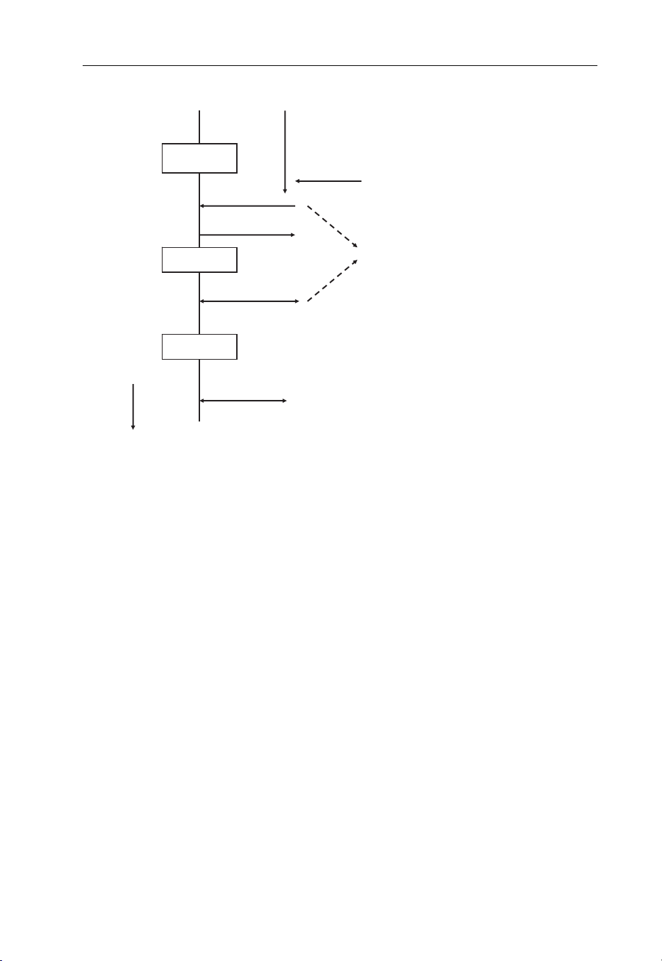
Beyond 3G Network Architectures 43
UE
URA-PCH
paging
paging response
Cell-FACH
re-establish bearers
Cell-DCH
data exchanged
time
Figure 2.11 Message exchange to move a mobile device from URA-PCH state back to cell-DCH
state when IP packets arrive from the network.
Network
IP packets arrive from
the network but cannot be delivered
as no bearer is established
High Speed Downlink Channels
used for transmitting RRC messages
to speed up the procedure
difficult to test and debug before. Already today, devices are tested with network
equipment of several vendors and different software versions. Adding yet another layer
of features will make this even more complex in the future.
2.2.5.5 Radio Network Enhancement: One-tunnel
Figure 2.12 shows the default path of user data between a mobile device and the Internet
through the cellular network. In the current architecture, the packet is sent through the
GGSN, the SGSN, the RNC and the base station. All user data packets are tunneled
through the network as described above, since the user’s location can change at any time.
The current architecture uses a tunnel between the GGSN and the SGSN and a second
tunnel between the SGSN and the RNC. All data packets therefore have to pass through
the SGSN, which terminates one tunnel, extracts the packets and puts them into another
tunnel. This requires both time and processing power.
Since both the RNC an d the GGSN are IP routers, this process is not required in most
cases. The one-tunnel approach, now standardized in 3GPP (see [16] and [17]), allows the
SGSN to create a direct tunnel between the RNC and the GGSN. It thus removes itself
from the transmission chain. Mobility management, however, remains on the SGSN
which means, for example that it continues to be responsible for mobility management
and tunnel modifications in case the mobile device is moved to an area served by another
Page 54
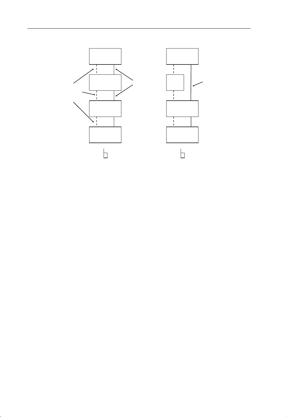
44 Beyond 3G – Bringing Networks, Terminals and the Web Together
Default Network Setup One-Tunnel SGSN Bypass
GGSN
signaling
(e.g. mobility
management)
Figure 2.12 Current network architecture vs the one-tunnel enhancement.
SGSN
RNC
NodeB
user data
tunnels
GGSN
SGSN
NodeB
one-tunnel
for user
data
RNC
RNC. For the user, this approach has the advantage that the packet delay is reduced.
From a network point of view, the advantage is that the SGSN requires fewer processing
resources per active user, which helps to reduce equipment costs. This is especially
important as the amount of data traversing the packet-switched core network is rising
significantly.
A scenario where the one-tunnel option is not applicable is international roaming.
Here, the SGSN has to be in the loop in order to count the traffic for inter-operator
billing purposes. Another case where the one-tunnel option cannot be used is when the
SGSN is asked by a prepaid system to monitor the traffic flow. This is only a small
limitation, however, since in practice it is also possible to perform prepaid billing via the
GGSN.
Proprietary enhancements even aim to terminate the user data tunnel at the NodeB,
bypassing the RNC as well. However, this has not found the widespread support of
companies in 3GPP and is not likely to be compatible with some HSPAþ extensions, like
the enhanced mobile device states.
2.2.5.6 Competition for LTE in 5 MHz
With the enhancements described in this section, it is quite likely that enhanced HSPA
networks become a viable alternative to LTE deployments in the short and medium term,
as the spectral efficiency in a 5 MHz band of both systems is similar. As will be described
in the next section, LTE scores over HSPA when more bandwidth is available, as it is not
limited to 5 MHz channels. In practice, it is thus likely that some network operators will
choose to improve their HSPA network and only later on move to LTE, while others will
prefer to go straight to LTE.
Page 55

Beyond 3G Network Architectures 45
2.3 LTE
2.3.1 Introduction
For several years, there has been an ongoing trend in fixed line networks to migrate all
circuit-switched services to a packet-switched IP infrastructure. In practice, it can be
observed that fixed line network operators are migrating their telephony services to a
packet-switched architecture offering both telephony and Internet access either via DSL
or a cable modem. This means, that circuit-switched technology is replaced by VoIPbased solutions, as will be described in more detail in Chapter 4. In wireless networks, this
trend has not yet begun. This is mostly due to the fact that current 3G and 3.5G network
architectures are still optimized for circuit-switched telephony both in the radio network
and in the core network. In addition, today’s VoIP telephony implementations significantly increase the amount of data that has to be transferred over the air interface, which
means fewer voice calls can be handled simultaneously. Besides these challenges, however, migrating voice telephony to IP offers a number of significant benefits such as
cheaper networks and integration with other IP-based applications as discussed in more
detail in Chapters 5 and 6.
At the same time, the general trend of ever increasing transmission bandwidths is
highlighting the limits of current 3G and 3.5G networks. It was therefore decided in
2005 by the 3GPP standardization body to start work on a next generation wireless
network design that is only based on packet-switched data transmission. This research
was performed in two study programs. The LTE program focused on the design of a
new radio network and air interface architecture. Slightly afterwards, work started on
the design of a new core network infrastructure with the Service Architecture
Evolution (SAE) program. Later, they were combined into a single work program,
the Evolved Packet System (EPS) program. By that time, however, the abbreviation
‘LTE’ was already dominant in literature and most documents still refer to LTE rather
than EPS.
Besides being fully packet-based, the following design goals were set for the new
network:
Reduced time for state changes – in HSPA networks today, the time it takes a mobile
device to connect to the network and start communication on a high-speed bearer is
relatively long. This has a negative impact on usability, as the user can feel this delay
when accessing a service on the Internet after a period of inactivity. It was thus decided
that with a new network design it should be possible to move from idle state to being
fully connected in less than 100 ms.
Reduced user plane latency – another downside of current cellular networks is the
much higher transmission delay compared with fixed line networks. While one-way
delay between a user’s computer at the edge of a DSL network to the Internet is around
15 ms today, HSPA networks have a delay of arou nd 50 ms. This is disadva ntageous
for applications such as telephony and real-time gaming. For LTE, it was decided that
air interface delay should be in the order of 5 ms to reach end-to-end delays equaling
fixed line networks.
Scalable bandwidth – HSPA networks are currently limited to a bandwidth of 5 MHz.
At some point, higher throughput can only be reasonably achieved by increasing the
Page 56

46 Beyond 3G – Bringing Networks, Terminals and the Web Together
bandwidth of the carrier. For certain applications, a carrier of 5 MHz is too large and it
was thus decided that the air interface should also be scalable in the other direction.
Throughput increase – for the new system, a maximum throughput under ideal
conditions of 100 Mbit/s should be achieved.
The following secti ons now describe how these design goals are met in practice.
2.3.2 Network Architecture
2.3.2.1 Enhanced Base Stations
Figure 2.11 shows the main components of an LTE core and radio access network as
described in [18]. Compared with UMTS, the radio network is less complex. It was
decided that central RNCs should be removed and their functionality has been partly
moved to the base stations and partly to the core network gateway. To differentiate
UMTS base stations from LTE base stations, they are referred to as Enhanced NodeB,
(eNodeB). As there is no central controlling element in the radio network any more, the
base stations now perform air interface traffic management autonomously and ensure
quality of service. This was already partly the case in UMTS with the introduction of
HSPA, as discussed in the previous section. Control over bearers for circuit-switched
voice telephony, however, rested with the RNC.
In addition, base stations are now also responsible for performing handovers for active
mobiles. For this purpose, the eNodeB can now communicate directly with each other via
the X2 interface. The interface is used to prepare a handover and can also be used to
forward user data (IP packets) from the current base station to the new base station to
minimize the amount of user data lost during the handover. As the X2 interface is
optional, base stations can also communicate with each other via the access gateway to
prepare a handover. In this case, however, user data is not forwarded during the handover. This means that some of the data already sent from the network to the current base
station might be lost, as once a handover decision has been made, it has to be executed as
quickly as possible before radio contact is lost. Unlike in UMTS, LTE radio networks
only perform hard handovers, that is only one cell communicates with a mobile device
at a time.
The interface that connects the eNodeB to the gateway nodes between the radio
network and the core network is the S1 interface. It is fully based on the IP protocol
and is therefore transport technology agnostic. This is a big difference to UMTS. Here,
the interfaces between the NodeB, the RNCs and the SGSN were firmly based on the
ATM protocol for the lower protocol layers. Between the RNC and the NodeB, IP was
not used at all for packet routing. While allowing for easy time synchronization between
the nodes, requiring the use of ATM for data transport on lower protocol layers makes
the setup inflexible and complicated. In recent years, the situation has worsened as rising
bandwidth demands cannot be satisfied any more with ATM connections over 2 Mbit/s
E-1 connections. The UMTS standard was thus enhanced to also use IP as a transport
protocol to the base station. LTE, however, is fully based on IP transport in the radio
network from day one. Base stations are either equipped with 100 Mbit/s or 1 Gbit/s
Ethernet ports, as known from the PC world, or with gigabit Ethernet fiber ports.
Page 57
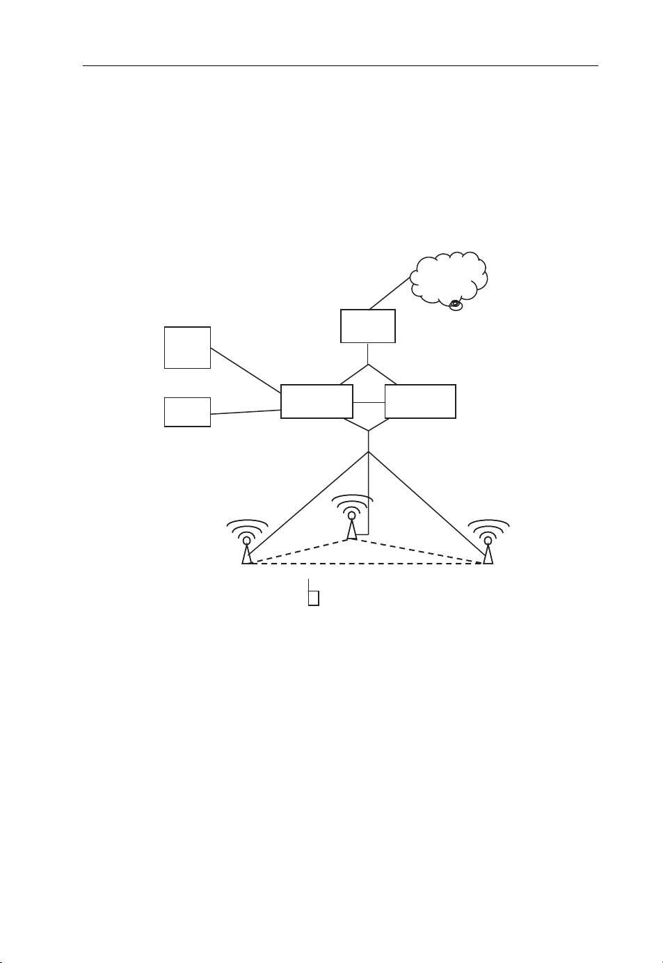
Beyond 3G Network Architectures 47
2.3.2.2 Core Network to Radio Access Network Interface
As shown in Figure 2.13, the gateway between the radio access network and the core
network is split into two logical entities, the Serving Gateway (Serving-GW) and the
Mobility Management Entity (MME). Together, they fulfill similar tasks as the SGSN
(Serving GPRS Support Node) in UMTS networks. In practice, both logical components
can be implemented on the same physical hardware or can be separated for independent
scalability.
PDN-GW
HSS
SCP
S6
MME
eNodeB
Mobile Device
Figure 2.13 Basic LTE network architecture.
S5
S11
X2
SGi
Serving-GW
S1
Internet
eNodeB
The MME is the ‘control plane’ entity responsible for the following tasks:
Subscriber mobility and session management signaling. This includes tasks such as
authentication, establishment of radio bearers, handover support between different
eNodeB and to/from different radio networks (e.g. GSM, UMTS).
Location tracking for mobile devices in idle mode, that is while no radio bearer is
established because they have not exchanged data packets with the network for a
prolonged amount of time.
Selection of a gateway to the Internet when the mobile requests the establishment of a
session, that is when it requests an IP address from the network.
Page 58

48 Beyond 3G – Bringing Networks, Terminals and the Web Together
The Serving Gateway is responsible for the ‘user plane’, that is, for forwarding IP
packets between mobile devices and the Internet. As already discussed in the section
on UMTS, IP tunnels are used in the radio access network and core network to
flexibly change the route of IP packets when the user i s handed over from one cell to
another while moving. The GPRS Tunneling Protocol (GTP) is reused for this
purpose and the mechanism is the same as shown for UMTS in Figure 2.3. The
difference from UMTS is that the tunnel for a user in the radio network is terminated
directly in the eNodeB itself and no longer on an intermediate component such as a
radio network controller. This means that the BTS is directly connected via an IP
interface to the Serving-Gateway and that different transport network technologies
such as Ethernet over fiber or optical cable, DSL, microwave, and so on, can be used.
In addition, the S1 interface design is much simpler than similar interfaces of
previous radio networks, which relied heavily on services of complex lower layer
protocols.
As the S1 interface is used for both user data (to the Serving-GW) and signaling data to
the MME, the higher layer protocol architecture is split into two different protocol sets:
the S1-C (control) interface is used for exchanging control messaging between a mobile
device and the MME. As will be shown below, these messages are exchanged over special
‘non-IP’ channels over the air interface and then put into IP packets by the NodeB before
they are forwarded to the MME. User data, however, is already transferred as IP packets
over the air interface and these are forwarded via the S1-U (user) protocol to the ServingGateway. The S1-U protocol is an adaptation of the GTP from GPRS and UMTS (cf.
Figure 2.3).
If the MME and the Serving Gateway are implemented separately, the S11 interface
is used to communicate between the two entities. Communication between the two
entities is required, for example for the creation of tunnels, when the user attaches to
the network, or for the modification of a tunnel, when a user moves from one cell
to another.
Unlike in previous wireless radio networks, where one access network gateway
(SGSN) was responsible for a certain number of radio network controllers and each
radio network controller in turn for a certa in number of base stations, the S1 interface
supports a meshed architecture. This means that not only one but several MMEs and
Serving-Gateways can communicate with each eNodeB and the number of MMEs and
Serving-Gateways can be different. This r educes the number of inter-MME handovers
when users are moving and allows the number of MMEs to evolve independently from
the number of Serving-Gateways, as the MME’s capacity depends on the signaling
load and the capacity of the Serving-Gateway depends on the user traffic load. These
can evolve differently over time, which makes separation of these entities interesting.
A meshed architecture of the S1 interface also adds redundancy to the network. If, for
example one MME fails, a second one can take over automatically if it is configured to
serve the same cells. The only impact of such an automatic failure recovery is that
users served by the failed MME have to register to the network again. How the
meshed capabilities of the S1 interface are used in practice depends on the policies
of the network operator and on the architecture of the underlying transport network
architecture.
Page 59

Beyond 3G Network Architectures 49
2.3.2.3 Gateway to the Inter net
As in previous network architectures, a router at the edge of the wireless core network
hides the mobility of the users from the Internet. In LTE, this router is referred to as the
Packet Data Network (PDN)-Gateway and fulfills the same tasks as the GGSN in
UMTS. In addition to hiding the mobility of the users, it also administers an IP address
pool and assigns IP addresses to mobiles registering to the network. Depending on
the number of users, a network has several PDN-Gateways. The number depends on
the capabilities of the hardware, the number of users and the average amount of data
traffic per user. As shown in Figure 2.13, the interface between the PDN-GW and
the MME/Serving-GWs is referred to as S5. Like the interface between the SGSN
and the GGSN in UMTS, it uses the GTP-U (user) protocol to tunnel user data
from and to the Serving-Gateways and the GTP-S (signaling) protocol for the initial
establishment of a user data tunnel and subsequent tunnel modifications when the user
moves between cells that are managed by different Serving-GWs.
2.3.2.4 Interface to the User Database
Another essential interface in LTE core networks is the S6 interface between the MMEs
and the database that stores subscription information. In UMTS, this database is referred
to as the Home Location Register. In LTE, the HLR is reused and has been renamed the
Home Subscriber Server (HSS). Essentially, the HSS is an enhanced HLR and contains
subscription information for GSM, GPRS, UMTS, LTE and the IP Multimedia
Subsystem (IMS), which is discussed in Chapter 4. Unlike in UMTS, however, the
S6 interface does not use the SS-7-based MAP (Mobile Application Part) protocol, but
the IP-based Diameter protocol. The HSS is a combined database and it is used simultaneously by GSM, UMTS and LTE networks belonging to the same operator. It therefore
continues to support the traditional MAP interface in addition to the S6 interface for LTE
and also the interfaces required for the IMS as discussed in Chapter 4.
2.3.2.5 Moving Between Radio Technologies
In practice, most network operators deploying an LTE network already have a GSM and
UMTS network in place. As the coverage area of a new LTE network is likely to be very
limited at first, it is essential that subscribers can move back and forth between the
different access network technologies without losing their connection and assigned IP
address. Figure 2.14 shows how this is done in practice when a user roams out of
the coverage area of an LTE network and into the coverage area of a UMTS network
of the same network operator. When the user moves out of the LTE coverage area, the
mobile device reports to the eNodeB that a UMTS (or GSM) cell has been found. This
report is forwarded to the MME which contacts the responsible 3G (or 2G) SGSN and
requests a handover procedure. The interface used for this purpose is referred to as S3 and
is based on the protocol used for inter-SGSN relocation procedures. As a consequence,
no software modifications are required on the 3G SGSN to support the procedure. Once
the 3G radio network has been prepared for the handover, the MME sends a handover
Page 60

50 Beyond 3G – Bringing Networks, Terminals and the Web Together
SGi
PDN-GW
S5
MME Serving-GW
S1
LTE eNodeB
Figure 2.14 LTE and UMTS interworking.
Internet
new tunnel (via S5 and S4)
S4
S3
3G SGSN
RNC
Handover
UMTS NodeB
command to the mobile device via the eNodeB. After the handover has been executed, the
user data tunnel between the Serving-GW and the eNodeB is re-routed to the SGSN. The
MME is then released from the subscriber management, as this task is taken over by the
SGSN. The Serving-GW, however, remains in the user data path via the S4 interface and
acts as a 3G GGSN from the point of view of the SGSN. From the SGSN’s point of view,
the S4 interface is therefore considered to be the 3G Gn interface between the SGSN and
the GGSN.
2.3.2.6 The Packet Call Becomes History
A big difference of LTE from GSM and UMTS is that mobile devices will always be
assigned an IP address as soon as they register to the network. This has not been the case
with GSM and UMTS because 2G, 3G and 3.5G devices are still mostly used for voice
telephony and so it makes sense to attach to the network without requesting an IP
address. In LTE networks, however, a device without an IP address is completely useless.
Hence, the LTE network attach procedure already includes the assignment of an IP
address. From the LAN/WLAN point of view this is nothing new. From a cellular
industry point of view, however, this is revolutionary. The GPRS and UMTS procedure
of ‘establishing a packet call’, a term coined with the old thinking of establishing a
circuit-switched connection with a voice call in mind, will therefore become a thing of
the past with LTE. Many people in the industry will have to change their picture of the
mobile world to accommodate this.
Page 61

Beyond 3G Network Architectures 51
2.3.3 Air Interface and Radio Network
While the general LTE network architecture is mainly a refinement of the 3G network
architecture, the air interface and the radio network have been redesigned from scratch.
In the 3GPP standards, a good place to start further research beyond what is covered
below is TS 36.300 [19].
2.3.3.1 Downlink Data Transmission
For transmission of data over the air interface, it was decided to use a new transmission
scheme in LTE which is completely different from the CDMA approach of UMTS.
Instead of using only one carrier over the broad frequency band, it was decided to use a
transmission scheme referred to as Orthogonal Frequency Division Multiple Access, or
OFDMA for short. OFDMA transmits a data stream by using several narrow-band
subcarriers simultane ously, for example 512, 1024, or even more, depending on the
overall available bandwidth of the channel (e.g. 5, 10, 20 MHz). As many bits are
transported in parallel, the transmission speed on each subcarrier can be much lower
than the overall resulting data rate. This is important in a practical radio environment in
order to minimize the effect of multipath fading created by slightly different arrival times
of the signal from different directions. The second reason this approach was selected was
because the effect of multipath fading and delay spread becomes independent of the
amount of bandwidth used for the channel. This is because the bandwidth of each
subcarrier remains the same and only the number of subcarriers is changed. With the
previously used CDMA modulation, using a 20 MHz carrier would have been impractical, as the time each bit was transmitted would have been so short that the interference
due to the delay spread on different paths of the signal would have become dominant.
Figure 2.15 shows how the input bits are first grouped and assigned for transmission
over different frequencies (subcarriers). In the example, 4 bits (representing a 16QAM
modulation) are sent per transmission step per subcarrier. A transmission step is also
referred to as a symbol. With 64QAM modulation, 6 bits are encoded in a single symbol,
raising the data rate further. On the other hand, encoding more bits in a single symbol
makes it harder for the receiver to decode the symbol if it was altered by interference. This
is the reason why different modulation schemes are used depending on transmission
conditions.
In theory, each subcarrier signal could be generated by a separate transmission chain
hardware block. The output of these blocks would then have to be summed up and the
resulting signal could then be sent over the air. Because of the high number of subcarriers
used, this approach is not feasible. Instead, a mathematical approach is taken as follows.
As each subcarrier is transmitted on a different frequency, a graph which shows the
frequency on the x-axis and the amplitude of each subcarrier on the y-axis can be
constructed. Then, a mathematical function called Inverse Fast Fourier Transformation
(IFFT) is applied, which transforms the diagram from the frequency domain to the time
domain. This diagram has the time on the x-axis and represents the same signal as would
have been generated by the separate transmission chains for each subcarrier when
summed up. The IFFT thus does exactly the same job as the separate transmission chains
for each subcarrier would do, including summing up the individual results.
Page 62

52 Beyond 3G – Bringing Networks, Terminals and the Web Together
t
OFDM(A)
1101110001
f
a
11
IFFT
01
b
c
11
d
00
01
e
A
A
Modulation &
Amplification
t
1101110001
abcde
a
b
c
d
e
A
detect
detect
detect
detect
detect
abcde
f
t
f
FFT
A
f
Amplification &
De-modulation
t
Figure 2.15 Principles of OFDMA for downlink transmissions.
On the receiver side, the signal is first demodulated and amplified. The result is then
treated by a fast Fourier transformation function which converts the time signal back
into the frequency domain. This reconstructs the frequency/amplitude diagram created
at the transmitter. At the center frequency of each subcarrier a detector function is then
used to generate the bits originally used to create the subcarrier.
The explanation has so far covered the Orthogonal Frequency Division aspect of
OFDMA transmissions. The Multiple Access (MA) part of the abbreviation refers to
the fact that the data sent in the downlink is received by several users simultaneously.
As will be discussed later, control messages inform mobile devices waiting for data which
part of the transmission is addressed to them and which part they can ignore. This is,
however, just a logical separation. On the physical layer, this only requires that modulation schemes ranging from QPSK over 16QAM to 64QAM can be quickly changed for
different subcarriers in order to accommodate the different reception conditions of
subscribers.
2.3.3.2 Uplink Data Transmission
For data transmission in the uplink direction, 3GPP has chosen a slightly different
modulation scheme. OFDMA transmission suffers from a high Peak to Average Power
Ratio (PAPR), which would have negative consequences for the design of an embedded
mobile transmitter; that is, when transmitting data from the mobile terminal to the
Page 63

Beyond 3G Network Architectures 53
network, a power amplifier is required to boost the outgoing signal to a level high enough
to be picked up by the network. The power amplifier is one of the biggest consumers of
energy in a device and should therefore be as power-efficient as possible to increase the
battery life of the device. The efficiency of a power amplifier depends on two factors:
The amplifier must be able to amplify the highest peak value of the wave. Due to silicon
constraints, the peak value determines the power consumption of the amplifier.
The peaks of the wave, however, do not transport any more information than the
average power of the signal over time. The transmission speed therefore does not
depend on the power output required for the peak values of the wave but rather on the
average power level.
As both power consumption and transmission speed are of impor tance for designers of
mobile devices, the power amplifier should consume as little energy as possible. Thus, the
lower the difference between the PAPR, the longer is the operating time of a mobile
device at a certain transmission speed compared with devices that use a modulation
scheme with a higher PAPR.
A modulation scheme similar to basic OFDMA, but with a much better PAPR, is
SC-FDMA (Single Carrier-Frequency Division Multiple Access). Due to its better
PAPR, it was chosen by 3GPP for transmitting data in the uplink direction. Despite
its name, SC-FDMA also transmits data over the air interface in many subcarriers, but
adds an additional processing step as shown in Figure 2.16. Instead of putting 2, 4 or
SC-FDMA
1101110001
detect
1101110001
t
FFT
IFFT
01
c
10
d
A
abcde
c
d
A
abcde
01
10
f
IFFT
f
f
FFT
f
AtA
t
A
0
0
0
Modulation &
Amplification
t
Amplification &
De-modulation
t
Figure 2.16 SC-FDMA modulation for uplink transmissions.
Page 64

54 Beyond 3G – Bringing Networks, Terminals and the Web Together
6 bits together as in the OFDM example to form the signal for one subcarrier, the
additional processing block in SC-FDMA spreads the information of each bit over all
the subcarriers. This is done as follows: again, a number of bits (e.g. 4 representing a
16QAM modulation) are grouped together. In OFDM, these groups of bits would have
been the input for the IDFT. In SC-FDMA, however, these bits are now piped into a
Fast Fourier Transformation (FFT) function first. The output of the process is the basis
for the creation of the subcarriers for the following IFFT. As not all subcarriers are used
by the mobile station; many of them are set to zero in the diagram. These may or may not
be used by other mobile stations.
On the receiver side the signal is demodulated, amplified and treated by the fast
Fourier transformation function in the same way as in OFDMA. The resulting amplitude
diagram, however, is not analyzed straight away to get the original data stream, but fed to
the inverse fast Fourier transformation function to remove the effect of the additional
signal processing originally done at the transmitter side. The result of the IFFT is again a
time domain signal. The time domain signal is now fed to a single detector block which
recreates the original bits. Therefore, instead of detecting the bits on many different
subcarriers, only a single detector is used on a single carrier.
The differences be tween OFDM and SC-FDMA can be summarized as follows:
OFDM takes groups of input bits (0s and 1s) to assemble the subcarriers which are
then processed by the IDFT to get a time signal. SC-FDMA in contrast first runs an FFT
over the groups of input bits to spread them over all subcarriers and then uses the result
for the IDFT which creates the time signal. This is why SC-FDMA is sometimes also
referred to as FFT spread OFDM.
2.3.3.3 Physical Parameters
For LTE, the following physical parameters have been selected:
Subcarrier spacing, 15 kHz.
OFDM symbol duration, 66.667 ms;
Standard cyclic prefix: 4.7ms. The cyclic prefix is transmitted before each OFDM
symbol to prevent inter-symbol interference due to different lengths of several trans-
mission paths. For difficult environments with highly diverse transmission paths a
longer cyclic prefix of 16.67 ms has been specified as well. The downside of using a
longer cycli c prefix, however, is a reduced user data speed since the symbol duration
remains the same.
The selected subcarrier spacing and symbol duration compensate for detrimental effects
on the signal such as the Doppler effect (frequency shift) due to the mobility of subscribers. The parameters have been chosen to allow speeds of beyond 350 km/h.
To be flexible with bandwidth allocations in different countries around the world, a
number of different channel bandwidths have been defined for LTE. These range from
1.25 MHz on the low end to 20 MHz on the high end. Table 2.1 shows the standardized
transmission bandwidths, the number of subcarriers used for each and the FFT size (the
number of spectral lines) used at the receiver side to convert the signal from the tim e to
Page 65

Beyond 3G Network Architectures 55
Table 2.1 Defined bandwidths for LTE.
Bandwidth Number of subcarriers FFT size
1.25 MHz 76 128
2.5 MHz 151 256
5 MHz 301 512
10 MHz 601 1024
15 MHz 901 1536
20 MHz 1201 2048
the frequency domain. In practice, it is expected that operators using LTE will deploy
networks in the frequency bands already available today for GSM and UMTS but use
bandwidths of at least 10 MHz, since there is no speed advantage of using LTE in a 5
MHz band over HSPAþ. The smaller bandwidths of 1.25MHz and 2.5 MHz were
specified for operators with little spectrum or for operators wishing to ‘re-farm’ some
of their GSM spectrum in the 900 MHz band. In practice, however, it is questionable if
this would bring a great ben efit since the achievable data rates in such a narrow band are
lower than what can be achieved with HSPA today.
In addition to the use of already existing frequency bands, new bands are being made
available for B3G wireless technologies. In Europe for example the 2.5 GHz band, also
referred to as the IMT extension band, will be opened for LTE and possibly other
wireless technologies. As will be shown in Chapter 3, however, there is still sufficient
unused bandwidth available in existing bands which might make new bands unattractive
for LTE in the near future.
2.3.3.4 From Slots to Frames
Data is mapped to subcarriers and symbols, which are arranged in the time and frequency
domain in a resource grid as shown in Figure 2.17. The smallest aggregation unit is
referred to as a slot or a resource block and contains 12 subcarriers and seven symbols on
each subcarrier in case the default short cyclic prefix is used. The symbol time of 66.67 ms
and the 4.7 ms cyclic prefix multiplied by 7 results in a slot length of 0.5 ms. In case the
long cyclic prefix has to be used, the number of symbols per slot is reduced to six, again
resulting in a slot length of 0.5 ms. The grouping of 12 subcarriers together results in a
resource block bandwidth of 180 kHz. As the total carrier band width used in LTE is
much larger (e.g. 10 MHz), many resource blocks are transmitted in parallel.
Two slots are then grouped into a subframe, which is also referred to as a Transmit
Time Interval (TT I). In case of Time Division Duplex (TDD) operation (uplink and
downlink in the same band), a subframe can be used for either uplink or downlink
transmission. It is up to the network to decide which subframes are used for which
direction. Most networks, however, are likely to use Frequency Division Duplex (FDD),
which means that there is a separate band for uplink and downlink transmission. Here,
all subframes of the band are dedicated to downlink or to uplink transmissions.
Page 66

56 Beyond 3G – Bringing Networks, Terminals and the Web Together
frequency
1 frame (10 ms) = 10 sub-frames (1ms)= 20 slots (0.5ms)
next frame
180 kHz
t
=
1 symbol =
1 resource element
(15 kHz)
1 resource block=
1 slot (0.5 ms) =
12 sub-carriers * 7 symbols
Figure 2.17 The LTE resource grid.
1 sub-frame
Ten subframes are grouped together to form a single radio frame, which has a duration
of 10 ms. Afterwards, the cycle repeat s with the next frame. This is important for mobile
devices because broadcast information (e.g. uplink bandwidth assignments) is always
transmitted at the beginning of a frame.
The smallest amount of resource elements (symbols) that can be allocated to a single
mobile device at an instant in time is two resource blocks, which equals one subframe or
one transmit time interval. To increase the data rate for the mobile device, the scheduler
in the network can concatenate several resource blocks in both the time and the frequency
direction. Since there are many resource blocks being transmitted in parallel, it is also
possible to schedule several mobile devices simultaneously, each listening to different
subcarriers.
2.3.3.5 Reference Symbols, Signals and Channels
Not all resource elements of a resource block are used for transmitting user data.
Especially around the center frequency, some resource elements are used for other
purposes, as described below.
To enable a mobile device to find the network after power on and when searching for
neighboring cells, some resource elements are used for pilot or reference symbols in a
predefined way. While data is transferred, pilot symbols are used by the mobile device for
downlink channel quality measurements and, since the content of the resource element
Page 67

Beyond 3G Network Architectures 57
is known, to estimate how to recreate the original signal that was distorted during
transmission.
For the transmission of higher layer data, LTE re-uses the channel concept of UMTS
as shown in Figures 2.8 and 2.9. Compared with UMTS, however, all devices use the
shared channel on the physical layer. The LTE channel model is therefore much simpler
than that of UMTS. LTE also re-uses the concept of logical channels (what is transmitted), transport channels (how is it transmitted) and physical channels (air interface) to
separate data transmission over the air interface from the logical representation of data.
Figure 2.18 shows the most important channels that are used in LTE and how they are
mapped to each other.
Downlink Uplink
logical
channels
(what)
BCCH
DTCH
DCCHPCCH
CCCH DCCH DTCH
transport
channels
(how)
physical
channels
PCH
Figure 2.18 LTE uplink and downlink channels.
BCH
DL-SCH
PDSCHPBCH
UL-SCH
PUSCH
RACH
PRACH
2.3.3.6 Downlink: Broadcast Channel
While no data is transmitted and the mobile is in idle state, it listens to two logical
channels. The logical Broadcast Control Channel (BCCH) is used by the network to
transmit system information to mobile devices such as the network and cell , that is, which
resource blocks and resource elements to find other channels, how the network can be
accessed, and so on. The basic parameters sent on the BCCH are mapped to the BCH
transport channel and the Physical Broadcast Channel (PBCH). The PBCH is then
mapped to dedicated resource elements in the subchannels of the inner 1.25 MHz of
the band. Which resource elements are used for the PBCH is calculated with a mathematical formula which generates a certain pattern and thus distributes the broadcast
information between different subcarriers over time [20]. In addition, a number of
additional resource elements are used for a Synchronization Channel (SCH), which is
not shown in Figure 2.19. As the name implies, these resource elements help mobile
devices to synchronize to the cell and to find the resource elements on which the broadcast information can be found. In addition to basic cell parameters, the broadcast
channel also carries further information which is necessary, but not essential from the
Page 68
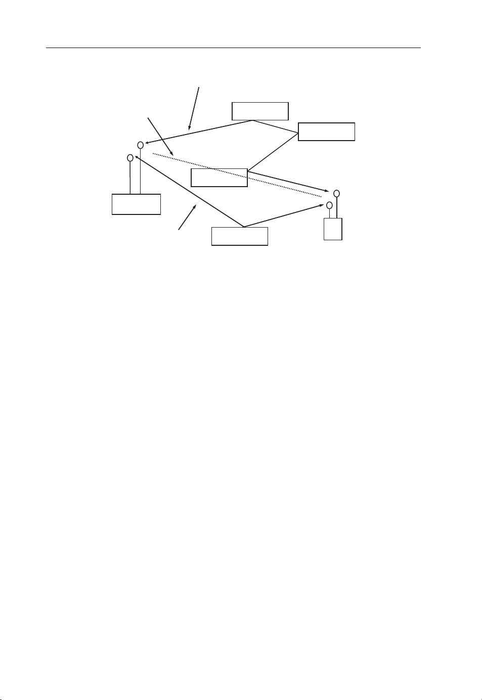
p
58 Beyond 3G – Bringing Networks, Terminals and the Web Together
first transmission
path
Direct line of
sight blocked
obstacle
BS
second
transmission
ath
Figure 2.19 Principle of MIMO transmissions. (Reproduced from Communication Systems for the
Mobile Information Society, Martin Sauter, 2006, John Wiley and Sons.)
obstacle
obstacle
obstacle
MS
start. To save bandwidth and to be flexible in the future, this information is not carried on
the PBCH but on the Physical Downlink Shared Channel (PDSCH) instead, which is also
used for transferring user data (IP packets). A pointer on the PBCH informs mobiles
where to find the broadcast information on the PDSCH.
2.3.3.7 Downlink: Paging Channel
The paging channel is used to contact mobile devices in an idle state when a new IP packet
arrives in the core network from the Internet and needs to be delivered to the mobile
device. In idle state, which is usually entered after a prolonged period of inactivity, only
the tracking area (i.e the identity for a group of cells) where the mobile is located is
known. The paging message is then sent into all cells of this group. When the mobile
device receives the message, it establishes a connection with the network again, a bearer is
set up and the packet is delivered. For services such as instant messaging, push e-mail and
VoIP, paging for incoming IP packets is quite common. Such applications, if programmed properly and no network address translation firewalls are used, have a logical
connection with a server in the network but are dormant until either the user invokes a
new action or the application is contacted by the network-based server, for example
because of a new instant message coming in [21]. As can be seen in Figure 2.18, there is no
physical channel dedicated for paging mess ages. Instead, paging messages are sent on the
downlink shared channel and a pointer on the logical broadcast channel indicates where
and when the paging messages can be found on the shared channel. The broadcast cycle
for paging messages a mobile device needs to listen to is usually in the order of 1–2 s. This
is a good balance between quick delivery of an incoming packet and power consumption
of a mobile device while not being actively used.
Page 69

Beyond 3G Network Architectures 59
2.3.3.8 Downlink and Uplink: Dedicated Traffic and Control Channels and Their
Mapping to the Shared Channel
From a logical point of view, user data and RRC control messages are transferred via
dedicated traffic channels and the dedicated control channels. Each mobile device has its
own dedicated pair of these channels. As can be seen in Figure 2.18, both channels are
multiplexed to a single physical downlink or uplink shared channel (PDSCH, PUSCH)
which are used for all devices. Higher softwar e layers are therefore independent of the
physical implementation of the air interface.
2.3.3.9 Downlink: Physical Layer Control Channels
In addition to the previously mentioned channels, there are a number of additional
physical layer control channels which are required to exchange physical layer feedback
information. As these channels only carry lower layer control information and are
originated by the base station and not the network behind them, they are not shown in
Figure 2.18.
To inform mobile devices which resource blocks are assigned to them for transmitting
in the uplink direction, the physical downlink shared channel is always accompanied by a
Physical Downlink Control Channel (PDCCH). In addition, this channel informs mobile
devices about the resource allocation of the PCH and the downlink shared channel.
Since the amount of data carried on the PDCCH varies, the number of OFDM
symbols assigned to the physical control channel is broadcast via the Physical Control
Format Indicator Channel (PCFICH). Finally, the Physical HARQ Indicator Channel
(PHICH) carries acknowledgements for proper reception of uplink data blocks. The
HARQ acknowledgment functionality used in LTE is similar to that used in UMTS. For
details, see Section 2.2.4.
2.3.3.10 Uplink: Physical Layer Control Channels
In the uplink direction there are two physical layer control channels: The physical uplink
control channel (PUCCH) is a per device channel and carries the following information:
HARQ acknowledgments for data frames received from the network. (cf. Section 2.2.4).
Scheduling requests from the mobile to inform the network that further uplink
transmit opportunities should be scheduled, as there is more data in the output buffer.
Channel Quality Indications (CQI) to the network, so the base station can determine
which modulation and coding to use for data in the downlink direction. CQI informa-
tion is also important for the scheduler in the base station, as it can decide to
temporarily halt data transmission to users in a temporary deep signal fading situation
where it is likely that data cannot be received correctly anyway.
The second control channel used in the uplink direction is the Physical Random Access
Channel (PRACH). It is used when no bearer is established in the uplink direction to
request new uplink transmission opportunities. It is also used when the mobile wants to
establish a bearer for the first time, after a long timeout or in response to a paging from
the network.
Page 70

60 Beyond 3G – Bringing Networks, Terminals and the Web Together
2.3.3.11 Dynamic and Persistent Scheduling Grants
The packet scheduler in the base station decides which resource blocks of the physical
downlink and uplink channels are used for which mobile device. This way, the base
station controls both uplink and downlink transmissions for each mobile and is therefore
able to determine how much bandwidth is available to a mobile device. Input parameters
for the scheduler are, for example the current radio conditions as seen from each device,
so the data transfer rate can be increased or decreased to mobiles temporarily experiencing exceptionally good or bad radio conditions. Other input parameters are the quality
of service parameters for a connection and the maximum bandwidth granted by the
operator to a mobile device, based on the user’s subscription.
There are two types of capacity grants for uplink data transmissions: dynamic grants
are announced once and are valid for one or more transmit time intervals. Afterwards,
the network has to issue a new grant for additional transmit opportunities or for the
mobile to receiver further data in the downlink direction. Dynamic grants are useful for
data that arrives in a bursty fashion, like during Web browsing, for example, and
sporadic downloading of content.
Applications such as voice and video calls require a constant bandwidth and as little
variation as possible in the time difference between two adjacent packets (jitter). For such
applications, the base station can also issue persistent grants which are given once and are
then valid for all subsequent transmit time intervals. This way, no signaling resources are
required to constantly re-assign air interface resources while a voice or video call is
ongoing. This increases the overall efficiency of the cell and increases the amount of
bandwidth that is available for user data. The issue arising with persistent grants is how
the base station can know when to use this type of assignment. One way to achieve this is
to base the decision on the connection’s quality of service req uirements which are
signaled to the network during bearer establis hment. This works well for applications
which require a constant bandwidth and are based on the IP Multimedia Subsystem. In
addition to the Quality of Service (QoS) signaling initiated by the mobile device, the IMS
has a connection to the transport network and can influence the bearer as well. This is
discussed in more detail in Chapter 4. For Internet-based voice and other applications
that are not using the IMS, however, using persistent grants is much more difficult. It is
likely that such applications are used over a default bearer which has no guaranteed
bandwidth and latency as it is used simultaneously for other applications on the same
device such as Web browsing. In practice, it remains to be seen if schedulers will also take
a look at the bandwidth usage of a mobile device over time and decide on this basis to use
persistent or dynamic grants.
2.3.3.12 MIMO Transmission
So far, this chapter has focused on data transmission via a single spatial stream between a
transmitter and receiver. Most wireless systems today operate in this mode and a second
transmitter on the same frequency is seen as unwanted interference that degrades the
channel. In practice, however, it can be observed that even a single signal is reflected and
scattered by objects in the transmission path and that the other end receives several copies
of the original signal from different angles at slightly different times. For simple wireless
Page 71

Beyond 3G Network Architectures 61
transmission technologies, these copies are also unwanted interference. LTE, however,
makes use of scattering and reflection on the transmission path by transmitting several
independent data streams via individual antennas. The antennas are spaced at least half a
wavelength apart, which in itself creates individual transmissions which behave differently when they meet obstacles in the transmission path. On the receiver side, the
different data streams are picked up by independent antenna and receiver chains.
Transmitting severa l independent signals over the same frequency band is also referred
to as Multiple Input Multiple Output, and Figure 2.19 shows a simplified graphical
representation. In practice, this means that several LTE resource grids, as shown in
Figure 2.17, are sent over the same frequency at the same time but via different antennas.
The LTE standard specifies two and four individual transmissions over the same band,
which requires two or four antennas at both the transmitter and receiver side respectively.
Consequently, such transmissions are referred to as 2 2 MIMO and 4 4 MIMO. In
practice, 2 2 MIMO is likely to be used at first, because of size constraints of mobile
devices and due to the fact that antennas have to be spaced at least half a wavelength
apart. Furthermore, most mobile devices support several frequency bands, each usually
requiring its own set of antennas in case MIMO operation is supported in the band. More
details on this topic will be discussed in Chapter 3 from a capacity point of view and in
Chapter 5 from a mobile hardware point of view. On the network side, 2 2 MIMO
transmissions can be achieved with a ‘single’ cross polar antenna that combines two
antennas in a way that each antenna transmits a separate data stream with a different
polarization (horizontal and vertical).
While Figure 2.19 depicts the general concept of MIMO transmission, it is inaccurate
at the receiver side, as each antenna receives not only a single signal but the combination
of all signals as they overlap in space. It is therefore necessary for each receiver chain to
calculate a channel propagation that takes all transmissions into account in order to
separate the different transmissions from each other. The pilot carriers mentioned above
are used for this purpose. The characteristics required for these calculations are the gain,
phase and multipath effects for each independent transmission path. A good mathematical introduction is given in [22].
As MIMO channels are separate from each other, 2 2 MIMO can increase the overall
data rate by two and 4 4 MIMO by four. This is, however, only possible under ideal
signal conditions. MIMO is thus only used for downlink transmissions since the base
station transmitter is less power-constrained than the uplink transmitter. In less favorable transmission conditions, the system automatically falls back to single stream transmission and also reduces modulation from 64QAM, to 16QAM or even QPSK. As has
been shown in the previous section on HSPAþ, there is also a tradeoff between higher
order modulation and MIMO use. Under less than ideal signal conditions, MIMO
transmission is therefore only used with 16QAM modulation, which fails to double the
data rate compared with a single stream transmission using 64QAM.
In the uplink direction, it is difficult for mobile devices to use MIMO due to their
limited antenna size and output power. As a result, uplink MIMO is currently not part of
the LTE standard. The uplink channel itself, however, is still suitable for uplink MIMO
transmissions. To fully use the channel, some companies are thinking about implementing collaborative MIMO in the future, also known as multiuser MIMO [23]. Here, two
mobile devices use the same uplink channel for their resource grid. At the base station
Page 72

62 Beyond 3G – Bringing Networks, Terminals and the Web Together
side, the two data streams are separated by the MIMO receiver and treated as two
transmissions from independent devices rather than two transmissions from a single
device that have to be combined. While this will not result in higher transmission speeds
per device, the overall uplink capacity of the cell is significantly increased.
2.3.3.13 LTE Throughput Calculations
Based on the radio layer parameters introduced in this section, the physical layer
throughput of an LTE radio cell can be calculated as follows: the transmission time per
symbol is 73.167 ms (66.667 ms for the symbol itself þ 4.7 ms for the cyclic prefix), the
highest modulation order is 64QAM (6 bits per symbol) and there are 1201 subcarriers in
a 20 MHz band:
Physical speed ¼ð1=0:000 073 167Þ
6
1201 ¼ 98:487:022 bit=s ði:e: about 100 Mbit=sÞ
When 2 2 MIMO is used, the physical layer speed doubles to about 200 Mbit/s and in
case 4 4 MIMO is used for transmission, the theoretical data transmission speed is
400 Mbit/s, based on a 20 MHz channel.
These values are usually quoted in press releases. However, as already discussed for
HSPA, these raw physical layer transmission speeds are not reached in practice for a
variety of reasons:
64QAM modulation can only be used very close to the base station. For the majority of
users served by a cell, 16QAM (4 bits per symbol) or QPSK (2 bits per symbol) is more
realistic.
Error detection and correction bits (coding) are usually added to the data stream as
otherwise the bit error rate over the air interface would become too high. Under
average signal conditions it is common to see coding rates of 1/3. In practice, the
coding overhead is thus in the range of 25–30%.
Retransmissions – with a very conservative transmission strategy, the coding described
above is sufficient to correct most transmission errors. In practice, however, more
aggressive transmission strategies are used to make the best use of air interface
resources. This usually results in air interface packet retransmission rates in
the order of 20%.
There is a significant overhead from pilot channels and control channels such as the
broadcast channel and the dedicated signaling channels per user to acknowledge the
correct reception of data packets and to convey signal quality measurement results.
Many of those channels are transmit ted with a lower order modulation so even devices
in very unfavorable signal conditions can receive the information.
In many cases, less than 20 MHz of bandwidth is available for LTE.
When using MIMO, the modulation order has to be reduced under less than ideal
transmission conditions.
The overall capacity of the cell has to be shared by all users.
The interference caused by transmissions of neighboring cells on the same frequency
band has a further detrimental effect.
Page 73

Beyond 3G Network Architectures 63
In practice, it is therefore likely that the throughput per cell is only about 30–50% of the
theoretical values given above. For a cell with a 10 MHz carrier and 2 2 MIMO, an
overall cell capacity on the IP layer of 30 Mbit/s may be achieved. A more detailed
capacity analysis can be found in Chapter 3.
2.3.3.14 Radio Resource Control
As in UMTS and HSPA, the LTE network controls access to the air interface resources
for both the uplink and the downlink. As there is no longer a central node in the radio
network for the administration of resources, the base stations themselves are now
responsible for the following tasks:
Broadcasting of system information.
Connection management – the mobile devices and the network use control channels
such as the random a ccess channel, the paging channel and the dedicated control
channels to exchange RRC messages. The first RRC messages exchanged when accessing the network for the first time, or after a long time of inactivity, are connection
establishment messages. The eNodeB is then responsible for setting up a logical
signaling bearer to the device via the shared uplink and downlink channel or denying
the request where the system is overloaded. Connection managem ent also includes the
establishment of dedicated bearers, again over the shared physical channel, based on
the quality of service parameters of the user’s subscription.
Measurement control – as users move, the radio environment is very dynamic and
devices therefore need to report signal strength measurements of the current and
neighboring cells to the network.
Mobility procedures – based on signal measurements of the mobile device, the eNodeB
can initiate a handover procedure to another cell or even to another radio network
such as UMTS or GSM/GPRS where the LTE coverage area is left.
2.3.3.15 RRC Active State
To minimize the use of resources in the network and to conserve the battery power of
mobile devices, there are several connection states. While data is exchanged between the
network and a mobile device, the RRC connection is in the active state. This means the
network can assign resources to the device on the shared channel at any time and data can
be inst antly transmitted. The mobile remains in active state even if no data is transferred
for some time, for example after the content of a Web page has been fully loaded. This
ensures instant package transmission without any further resource control overhead, for
example when the user clicks on a link.
While in full active state, the mobile has few opportunities to deactivate its receiver
which has a negative impact on the battery capacity. After some time of inactivity, the
network can thus decide to activate a Discontinuous Reception Mode (DRX) while the
mobile is still in active state. This means that the mobile only has to listen to downlink
bandwidth assignments and control commands periodically and can switch off its
receiver at all other times. The DRX interval is flexible and can range from milliseconds
to seconds.
Page 74

64 Beyond 3G – Bringing Networks, Terminals and the Web Together
Even while in DRX mode, mobilityis still controlled by the network. This means that the
mobile device has to continue sending signal measurement results to the network when a
defined high or low signal threshold for the current cell or a neighboring cell is met. The
eNodeB can then at any time initiate a handover procedure to another cell if required.
2.3.3.16 RRC Idle State
If no packets have been transmitted for a prolonged amount of time, the eNodeB can put
the connection to a user in RRC Idle state. This means that, while the logical connection
to the network and the IP address is retained, the radio connection is removed. The MME
is informed of this state change as well, as IP packets arriving from the Internet can no
longer be delivered to the radio network. As a consequence, on receipt of IP packets the
MME needs to send a paging message to the mobile device, which leads to the
re-establishment of a radio bearer. In case the mobile device needs to send an IP packet
while in RRC idle state, for example because the user has clicked on a link on a Web page
after a long time of inactivity, it also has to request the establishment of a new radio
bearer before the packet can be transmitted.
Furthermore, the network no longer controls the mobility of a device in RRC idle state
and the device can decide on its own to move from one cell to another. Several cells are
grouped into a tracking area, which is similar to location and routing areas used in
UMTS. The mobile only reports a cell change to the network if it selects a cell which
belongs to a different tracking area. This means that the network, or more specifically the
MME, has to send a paging message via all the cells that belong to the tracking area when
a new packet for the device arrives from the Internet.
2.3.3.17 Treatment of Data Packets in the eNodeB
In addition to radio resource specific tasks, the eNodeB is also responsible for several
tasks concerning the data packets themselves before they are transmitted over the air
interface. To prevent data modification attacks, also referred to as man-in-the-middle
attacks, an integrity checksum is calculated for each data packet before it is sent over the
air interface. Input to the integ rity checksum algorithm is not only the content of the
packet but also an integrity checking key which is calculated from a unique secret key
that is shared between the eNodeB and each mobile device. If a message is fraudulently
modified on the air interface, it is not possible to append a valid integrity checksum due to
the missing key and the message is not accepted by the recipient. Integrity checking
applies to IP packets, to radio resource control messages exchanged with the eNodeB and
also to mobility and session management messages exchanged with the MME.
In addition to integrity checking, data packets are encrypted before being transmitted
over the air interface. Again, the subscriber’s individual shared secret key, stored on the
SIM card and the HSS, is used to calculate a ciphering key on both sides of the
connection. Data intercepted on the air interface can thus not be decoded as the ciphering
key is not known to an attacker. Ciphering applies to IP packets, to radio resource
control messages and also to mobility and session management messages, the latter two
not being based on IP.
Page 75

Beyond 3G Network Architectures 65
A task only performed on user data IP packets before they are transmitted over the air
interface is header compression. For LTE networks, this feature is very important,
especially for real-time applications such as VoIP. As VoIP is very delay-sensitive,
typically only 20 ms of speech data is accumulated in a single IP packet. With a data
rate of around 12 kbit/s produced by sophisticated speech codecs, such as an Adaptive
Multi-Rate (AMR) codec with a good voice quality, each IP packet carries around 32
bytes of data. In addition, there is an overhead of 40 bytes for an IPv4 header, the UDP
header and the RTP header. W ith IPv6, the overhead is even larger due to the use of 128
bit IP addresses and additional header fields. This means that there is more overhead per
packet than speech data. This greatly inflates the required data rate and therefore
significantly reduces the potential number of simultaneous calls per base station. As
voice calls are likely to be an important feature for LTE networks, it is necessary to
compress IP packet headers before transmission. For LTE, the Robust Header
Compression (ROHC) algorithm, originally specified in [24], was selected. Its advantages are:
A very good compression ratio. The 40 bytes overhead of various encapsulated
protocols are typically reduced to 6 bytes.
A built-in feedback mechanism detects compression process corruptions as a result of
air interface transmission errors. This allows an immediate restart of the compressor
logic instead of letting the error propagate into the compression process of subsequent
packets, as was the case with previously used header compression algorithms.
The ROHC algorithm not only compresses the IP header but analyzes the IP packet
and also compresses further encapsulated headers such as the UDP header and the
RTP (Real-time Transfer Protocol) header where the data packet contains audio
information.
In order not to focus only on VoIP packets, ROHC is able to detect different header
types in a packet and selects an appropriate overall header compression algorithm for
each packet. The different compression algorithms are referred to as profiles. For
VoIP packets, the RTP profile is used, whi ch compresses the IP header, the UDP
header and the RTP header of the packet. Further profiles are the UDP profile, which
compresses IP and UDP headers (e.g. of SIP signaling messages, cf. Chapter 4), and the
ESP (Encapsulated Security Payload) profile, which is used for compressing headers of
IPsec encrypted packets.
Integrity checking, ciphering and compression are all part of the Packet Data
Convergence Protocol (PDCP), which sits below the IP layer and thus encapsulates IP
packets. The packet size, howeve r, does not usually increase, as the additional PDCP
header overhead is more than made up for by the header compression.
2.3.4 Basic Procedures
An important aspect of LTE, in addition to increasing the available bandwidth over the
air interface, is to streamline signaling procedures to reduce delay for procedures such as
setting up an initial connection and resuming data transfers from idle state. Figure 2.20
Page 76

66 Beyond 3G – Bringing Networks, Terminals and the Web Together
Mobile
Device
broadcast
to find network
Random Access Procedure
Attach request
Authentication Procedure
Bearer establishment
request
Bearer est. ack.
eNodeB
Attach request
Attach accept
MME
Update location
Insert subscr. data
Insert s. data ack.
Update location ack.
HSS
Create bearer request
Create ack.
Serving-GW
Create bearer request
PDN-GW
Create ack.
Figure 2.20 Attaching to the LTE network and requesting an IP address.
shows the message exchange of a device attaching to the network after it has been
switched on until the point an IP address is assigned. Attaching to the network and
getting an IP address is, as mentioned before, a single procedu re in LTE as all services are
based on IP. It does not make sense, therefore, to attach to the network without
requesting an IP address as is the case today in GSM and UMTS networks.
2.3.4.1 Network Search and Broadcasting System Information
The first step in attaching to the network after power on is to find all available networks
and select an appropriate network to commun icate with. For this, the mobile performs
an initial scan in all frequency bands it supports and tries to find downlink synchronization signals. As most LTE-capable devices also support 2G and 3G networks such as
GSM and UMTS, the network search procedure also includes such networks. As most
bands are not dedicated to a single network technology, the mobile must be able to
correlate downlink signals to different radio systems. In case of LTE, the mobile searches
for synchronization signals which are placed at regular intervals in the center subchannels (1.25 MHz) of an LTE carrier. Once these are found and properly decoded, the
broadcast channel can be read and the mobile downloads the cell’s complete system
information. In most cases, the mobile device starts its search on the last used channel
before it was switched off. If the device has not moved since it has powered off, the
network is found very quickly. If a network is found, the registration process continues. If
not, the process is repeated until the network is found or all supported frequency bands
Page 77

Beyond 3G Network Architectures 67
have been searched. Where the last used network before the device was powered down is
not found, the mobile either selects a network on its own based on the preferences stored
on the SIM card or presents the list of detected networks to the user who can then select
the network of their choice (e.g. in case of roaming).
2.3.4.2 Initial Contact with the Network
After the broadcast information of a cell has been read and the decision has been
made to use the network, the mobile devicecanattempttoestablishaninitial
connection by sending a short message on the random access channel. The channel
is referred to as a r andom access channel as the network cannot control access to
this channel. There i s thus a chance that several devices attempt to send a message
simultaneously which results in a network access collision. If this happens, the base
station will not be able to receive any of the messages properly. To minimize this
possibility, the message itself is only very short and only contains a 5 bit random
number. Furthermore, the network offers many random access slots per second
to randomize access requests over time. When the network picks up the random
access request, it assigns a C-RNTI (Cell-Radio Network Temporary) identifier to
the mobile and answers the message with a Random Access Response message. The
message contains the 5 bit random number, so the mobile device can correlate the
response to the initial message and the C-RNTI, which is used to identify
the mobile device from now until the physical connection to the network is released
(e.g. after a l onger time of inactivity). In addition, the message contains an initial
uplink bandwidth grant, that is a set of resource blocks of the shared uplink
channel that the mobile device can use in uplink direction. These resources are
then used to send the RRC connection request message that encapsulates an initial
attach request.
2.3.4.3 Authentication
When the eNodeB receives the connection request mess age, it forwards the contained
attach request to the MME. The MME extracts the user identity from the message which
is either the International Mobile Subscriber Identity or a temporary identity that was
assigned to the mobile device during a previous connection with the netwo rk. In most
cases, a temporary identity is sent which is changed once the user has been authenticated
to reduce the number of IMSIs that have to be transmitted before encryption can be
activated. If the IMSI of the subscriber is not known to the MME, the Authentication
Center in the HSS is queried for authentication information. If a temporary identity is
sent that is unknown to the MME, a request is sent to the mobile to send its IMSI instead.
Afterwards, the network and mobile authenticate each other using secret private keys
which are stored both on the SIM cards and in the authentication center, which is part of
the HSS. Once the subscriber is properly authenticated, the eNodeB and the mobile
device activate air interface encryption. At the same time, the MME continues the attach
process by informing the HSS with an Update Location message that the subscriber is
now properly authenticated. The HSS in turn sends the user’s subscription data, for
Page 78

68 Beyond 3G – Bringing Networks, Terminals and the Web Together
example what types of connections and services the user is allowed to use, to the MME in
an Insert Subscriber Data Message. The MM E confirms the reception of the message
which in turn terminates the Update Location procedure with an acknowledgement
message from the HSS, as shown in Figure 2.20.
2.3.4.4 Requesting an IP Address
In the next step, the MME then requests an IP address for the subscriber from the
PDN-GW via the Serving-GW with a Create Bearer Request message. When the
PDN GW receives the message it ta kes an IP address from its address pool, creates
a subscriber tunnel endpoint and r eturns the IP address to the MME, again via the
Serving-GW. Involving the Serving-GW in the process is required, as the user data
tunnel is not established between the MME and the PDN-GW but between the
Serving-GW and the PDN-GW. Once the MME receives the IP address, it forwards it to the eNodeB in an Attach Accept message, which is the reply to the
initial Attach Request message. The eNodeB in turn forwards the Attach Accept
message including the IP address as part of a Radio Bearer Establishment Request
Message to the mobile device, which answers with a Radio Bearer Establishment
Response message containing an Attach Complete message. The Attach Complete
Message is then forwarded to the MME and the mobile device can now communicate with the Internet or the network operator’s internal IP network (e.g. to
connect to the IMS).
Despite the many messages being sent back and forth between the different functions
in the network, the number of messages exchanged between the mobile device and the
network has been reduced compared with GSM and UMTS by performing several tasks
with a single message. This should significantly speed up the overall process. Excluding
network detection and reading the broadcast channel, the procedure is likely to take only
a few hundred milliseconds.
2.3.5 Summary and Comparison with HSPA
At its introduction, LTE competes with already deployed HSPA networks. It is likely,
that some network operators will decide to upgrade their HSPA networks and eventually
upgrade the network for the use of higher-order modulation, MIMO and Ethernet-based
backhaul. In a 5 MHz band, the performance of LTE and HSPAþ is similar, so other
reasons are required for operators to add LTE to their already existing GSM and HSPA
infrastructure. One reason for adding LTE to a cell site is to increase the available
bandwidth for a certain region by off-loading traffic from HSPA to LTE, once LTE
devices become more commonplace. As network v endors are offering base stations
capable of supporting several radio technologies simultaneously, the move to LTE
could come as part of replacing aging base stations. By 2012, for example, many
UMTS base stations will have been in the field for almost 10 years and therefore will
have to be replaced anyway. Since it is unlikely that HSPA will be directly replaced by
LTE due to many devices still ‘only’ being HSPA-capable, multiradio technology base
stations will become very interesting for mobile network operators. If LTE is used in the
Page 79

Beyond 3G Network Architectures 69
same band as the other radio technologies, a single antenna can be used. Therefore, no
additional antennas will be required for many base station sites. The existing antenna
might be replaced with a new one, however, to enable MIMO transmissions for LTE.
When more than a 5 MHz bandwidth is available, LTE can clearly show its advantages
over 3G technologies, as LTE radio channels can be easily extended to 10, 15 or even
20 MHz. In addition, the simpler radio and core network with fewer components and
new technologies for backhaul transmission from the base station to the rest of the
network will lower network operation costs. This will be an interesting driver for network
operators, as bandwidth demands keep rising while the revenue per user is flat or even
declining. Finally, due to the simplified air interface signaling, LTE is much more suitable
for always-on IP connectivity and applications such as instant messaging and push
e-mail, which frequently communicate with the network, even while the mobil e device
is not actively used.
2.3.6 LTE-Advanced
As discus sed in Section 1.5, LTE is unlikely to meet the transmission speed requirements
of the ITU for 4G wireless systems. 3GPP has therefore started to investigate, how an
evolution of LTE could meet these requirements. The following list shows some initial
ideas for such a system, currently referred to as LTE-Advanced and LTE Plus, which
were presented during a 3GPP worksh op in 2008 [25]:
LTE advanced shall be backwards-compatible to LTE (i.e. like HSPA is backwardscompatible to UMTS).
The primary focus should be on low-mobility users in order to reach ITU-Advanced
data rates.
Channel bandwidths should be used beyond the 20 MHz currently standardized for
LTE (e.g. 50 MHz, 100 MHz).
The number of antennas for MIMO should be increased beyond what is currently
specified in LTE.
MIMO should be combined with beamforming.
There should be a further increase in Voice over IP capacity.
Cell edge data rates should be further improved.
Self-configuration of the network should be improved.
Details for these and other possible features for LTE-Advanced can be found in [26].
With LTE still in the specification phase and not yet being widely deployed, working on a
further evolution presents a significant challenge to 3GPP members for a number of
reasons. First, it is likely that significant work on the original LTE and SAE standards
will be required beyond 2008. This leaves little room for significant simultaneous developments. Also, there has not yet been much time to allow for adjustments of the
standards based on the experience gained from developing and deploying LTE.
Finally, some network operators might decide to halt their LTE plans and focus on
improving their current HSPA networks to try to bridge the time until LTE-Advanced
systems become avail able.
Page 80

70 Beyond 3G – Bringing Networks, Terminals and the Web Together
2.4 802.16 WiMAX
2.4.1 Introduction
Another successor to current 3.5G wireless network technologies is WiMAX, a system
based on the IEEE (Institute of Electrical and Electronics Engineers) 802.16 air interface
standard. Major infrastructure vendors backing this technology are, for example, Intel,
Motorola, Nortel, Alcatel-Lucent and Nokia Siemens Networks. As will be shown in this
section, WiMAX shares many basic properties with LTE. From a timing perspective,
WiMAX has a head start over LTE, as standards activities were started earlier.
While LTE is mainly attractive for incumbent 2G and 3G operators, WiMAX is very
appealing to greenfield network operators, that is operators without an already existing
network in place. There are several reasons for this:
In most countries, frequency bands for UMTS and LTE have already been sold many
years ago. WiMAX, however, can be operated in so far unused frequency bands that
are still in the process of being auctioned.
The WiMAX network architecture is fully based on IP, which simplifies the network
architecture design and deployment and cuts operating costs compared with current
ATM backhaul-based 3G networks.
New network operators are aiming to offer Internet access and thus compete with fixed
line high-speed Internet solutions such as DSL and TV cable. As a consequence, their
business model is quite different from that of incumbent wireless network operators,
who are still mainly focused on mobile voice services.
WiMAX network equipment is available today, while LTE equipment will only
become commercially available in the 2010–2012 timeframe.
An exception to the rule seems to be the US market, where Sprint, a major incumbent
operator, together with Clearwire has decided to use WiMAX due to a lack of a
convincing future perspective of its 3G technology.
2.4.2 Network Architecture
2.4.2.1 Small Networks for Stationary Clients
Many early WiMAX network operators have started to deploy small networks based on
the early 802.16-2004 standard (previously referred to as 802.16d), which mainly targeted
stationary devices with roof-mounted antennas or indoor WiMAX routers with large
omnidirectional antennas built in. Such networks require little more than a few base
stations and possibly a central server for storing subscription data for subscriber authentication purposes and to control access to the network. Since such networks are designed
for stationary devices, no handovers of connections between base stations are required.
Each cell can therefore act as a little network of its own.
2.4.2.2 Medium to Large Networks and Mobility
More recently, the air interface standard was enhanced to also support mobility of
subscribers, including handovers from one base station to another. This version of the
Page 81

Beyond 3G Network Architectures 71
standard is referred to as 802.16e, or 802.16-2005. Since handovers and mobile subscribers require more administration in the network, it became necessary to also specify the
network behind the base stations. As the IEEE is only responsible for the air interface
standardization, this part was taken over by the WiMAX Forum [27]. Standardizing the
radio network and the core network is an important task, since only standardized
functionalities and interfaces allow network operators to select compatible components
from a wide variety of network vendors. This way, competition between vendors is
fostered, which results in lower prices for network equipment. To ensure interoperability
of components from different vendors, the WiMAX Forum is also in charge of a
certification program for base stations, end user devices and other network equipment.
Figure 2.21 shows how one of the possible WiMAX network infrastructure setups looks
like in practice. When compared with the LTE network infrastructure shown in
Figure 2.14, there are remarkable similarities. As in LTE, WiMAX base stations communicate with each other for handovers. Furthermore, there is no central element in the radio
network, as was the case with UMTS. Instead, WiMAX networks only require gateways
between the radio network and the core network, the Access Service Network Gateways
(ASN-GW).The ASN-GWs are responsible for user management and mobility.
ASN
BS
R1
(802.16)
R8
R8
BS
BS
BS
BS
BS
R6
…
ASN
R6
…
ASN-GW
R8 R4
ASN-GW
R3
R3
Core Network
HA
AAA
IMS
DNS
DHCP
R5 (roaming)
Figure 2.21 WiMAX network architecture. (Reproduced from Communication Systems for the
Mobile Information Society, Martin Sauter, 2006, John Wiley and Sons.)
The air interface between mobile devices and the base stat ion is referred to as the R1
reference point or interface. In this section, the two words are used interchangeably. The
protocol used over this interface is either 802.16-2004 (formerly 802.16d) for stationary
wireless installations or 802.16-2005 (formerly 802.16e) for both stationary and mobile
clients. Air interface details are discussed in Section 2.4.3.
In the radio network, base stations are connected to the ASN-GW via the R6 reference
point. In the first version of the WiMAX standard, the interface is proprietary, which
Page 82

72 Beyond 3G – Bringing Networks, Terminals and the Web Together
means that an ASN-GW and all base stations connected to it need to be from the same
vendor. In the second version of the standard, the R6 reference point will also be
standardized to allow mixed configurations. This further increases competition, which
results in more competitive pricing. Like in LTE, the R6 interface be tween the base
station and the access gateway is fully based on IP. Consequently, any transport technology that is capable of carrying IP packets can be used. Since multisector WiMAX base
stations are capable of air interface data rates of 30 Mbit/s and beyond, as shown in
Chapter 3, suitable transport technologies in the last mile to the base station are
Ethernet-based microwave systems, VDSL and fiber connections. Because of the prohibitive cost of such connections and their slow sp eed compared with the capabilities of the
air interface, 2 Mbit/s E-1-based co nnectivity is not likely to be used.
For smooth handovers of connections between base stations, the R8 reference point
has been defined as shown in Figure 2.21. Like the R6 reference point, it is also fully
based on the IP protocol. In practice, a base station is only co nnected to the network with
a single physical interface. Data between different base stations therefore trave rses one or
more routers before reaching another base station. In practice, the overhead created by
this is likely to be small, as the amount of user data on the R6 interface is likely to be
several orders of magnitude higher than the amount of data exchanged for a handover of
a connection on the R8 interface.
2.4.2.3 The Access Service Network Gateway
In WiMAX networks, the gateway between the radio network and the core network is
referred to as the Access Service Network Gateway. In principle, it is responsible for the
same tasks as the Access Gateway (AGW) in LTE. These are:
subscriber management tasks such as authentication and subscription management;
mobility management to redirect the connection from one cell to another when the user
is moving;
to actively support the handover procedure in case the R8 reference poin t between two
base stations is missing.
2.4.2.4 Authentication and Ciphering
In the WiMAX standard, user devices are referred to as a Customer Premises Equipment
(CPE), a term from the 802.16-2004 standard, which mainly addressed stationary equipment. The term, however, is still being used with the 802.16-2005 standard and mobile
devices alongside the term Mobile Subscriber Station (MSS). When a device is powered
on, its first task is to search for available networks and to get an IP address from the
user’s home network, or , in the case of roaming, from another suitable network. Before a
device is admitted to the network by the ASN-GW, an authentication procedure is
required. Unlike 3GPP networks such as UMTS and LTE, WiMAX does not make
use of a secret key that is stored on a SIM card and in the network. Instead, authentication is performed with a public/private key pair in addition to an X.509 certificate.
In theory, the keys and the certificate could be stored on a SIM card. In practice,
however, this is not the case today. Instead, the keys and certificate are stored in a safe
Page 83

g
Beyond 3G Network Architectures 73
location in the device itself that cannot be directly accessed to prevent applications from
reading the secret private key.
At the beginning of the authentication procedure, the device and the network exchange
their public keys with each other, which are then used to derive temporary keys to encrypt
further traffic. Data encrypted with a temporary public key can only be decrypted with
the corresponding temporary private key which was derived from the secret private key.
As private keys are never transmitted over the air interface, it ensures that an attacker
cannot decipher or modif y the data. Another benefit of having public/private keys is that
the private key of the subscriber is only stored in the client device but not in the network,
as the network only requires the public key for encrypting the data. Consequently, no
sensitive key information has to be stored on any equipment of the network operator.
In addition to the public key exchange, an additional mechanism is used to ensure that
the public key sent by a device is tied to its MAC hardware address. This is done by
sending a certificate, signed by a certificate authority, in addition to the public key, as
shown in Figure 2.22. The certificate authority signs the certificate by encrypting the
device’s public key and MAC hardware address with its private key. When the client
device sends its public key together with the certificate, the network then decrypts the
certificate with the public key of the certificate authority. Afterwards, it checks if the
subscriber’s public key matches the one extracted from the certificate. Furthermore, it is
verified that the MAC address, which is part of each data packet, also matches the one
given in the certificate. If they match, the client device is authenticated. Tampering with
the certificate is not possible since it can only be decrypted by everyone who knows the
public key of the certificate authority. However, it cannot be changed and re-encrypted.
The certificate also prevents a successful attack by duplicating MAC addresses, as the
private key of the original device used in combination with a MAC address is securely
stored in the device. Therefore, it cannot be duplicated together with the MAC address.
CA
1. Manufacturer gets a certificate
from CA that links the
MAC address and public key.
CPE
2. During authentication, client
sends certificate to network.
Figure 2.22 WiMAX authentication with the help of a Certificate Authority (CA). (Reproduced
from Communication Systems for the Mobile Information Society, Martin Sauter, 2006, John Wiley
and Sons.)
3. Network has public key of the
trusted CA and can thus verify
the certificate.
Network
4. Client is authenticated and the
public key of the client contained in
the certificate is used to encrypt
the remainin
authentication process.
Page 84

74 Beyond 3G – Bringing Networks, Terminals and the Web Together
It should be noted that certificates and public/private keys are also used for authentication and encryption of secure Web sessions, such as for example for online shopping or
Web banking. Here, a Secure HTTP (HTTPS) session is established instead of a standard
HTTP session and the process is very similar to the one described above. During
connection establishment, the Web server sends a certificate signed by a certificate
authority to the Web browser. The certificate contains the URL of the Web site and
the public key. The Web browser compares the URL the user has typed in with the one in
the certificate. If both match, the Web browser can be certain that the connection was not
redirected by an attacker. To an attacker, the public key in the certificate is worthless, as
they do not have the private key to decrypt the information, which is encrypted by the
client with the public key.
Both the WiMAX and the HTTPS authentication processes require certificates to be
generated by a trusted certificate authority. Trust is established by storing the certificate
authority’s public key locally. In the case of WiMAX, the certificate authority’s public
key is stored in the device itself. In case of HTTPS, the certificate authority’s public key is
stored in the Web browser. In practice, there are many different certificate authorities
that can issue certificates. Verisign, for example is a company issuing both HTTPS and
WiMAX certificates [28].
2.4.2.5 Client IP Address Assignments and R6 Tunnels
Once a device is authenticated and air interface ciphering has been activated, the ASNGW is also in charge of assigning an IP address to a device or to request it from a Home
Agent (HA) in the core network, as will be discussed below in Section 2.4.2.7.
As the network between the base stations and ASN-GWs is not necessarily owned by
the WiMAX network operator, data traffic on the R6 reference point between gateways
and base stations should be encrypted. For this purpose, an encrypted IPSec tunnel
could be established between each base station and the ASN-GW. The user’s data is thus
not only protected on the air interface, but also throughout the radio network up to the
ASN-GW.
2.4.2.6 Micro Mobility Management
When a user moves from the coverage area of one base station to another, it is the base
station’s task to handover the connection. Both the network and the client device can
initiate a handover. In the radio network, this means that the current and new base
station communicate with each other over the R8 interface or via the ASN-GW during
the handover. Part of the handover process is also to inform the ASN-GW that the
location of the subscriber has changed, as user data packets now have to be exchanged
over a different IPSec tunnel. Figure 2.23 shows how this works in practice. In the
example, base stations and ASN-GWs in the radio network use the 10.x.x.x IP subnet.
One tunnel is established between the upper base station, which has been assigned
10.0.0.2 as an IP address, and the ASN-GW (10.0.0.1). Another tunnel is established to
the base station in the lower part of the figure (10. 0.0.3). Before the handover, the user’s
data, identified by the user’s IP address (195.36.219.196), is sent through the tunnel
between 10.0.0.1 (ASN-GW) and the upper base station (10.0.0.2). Once the handover
Page 85
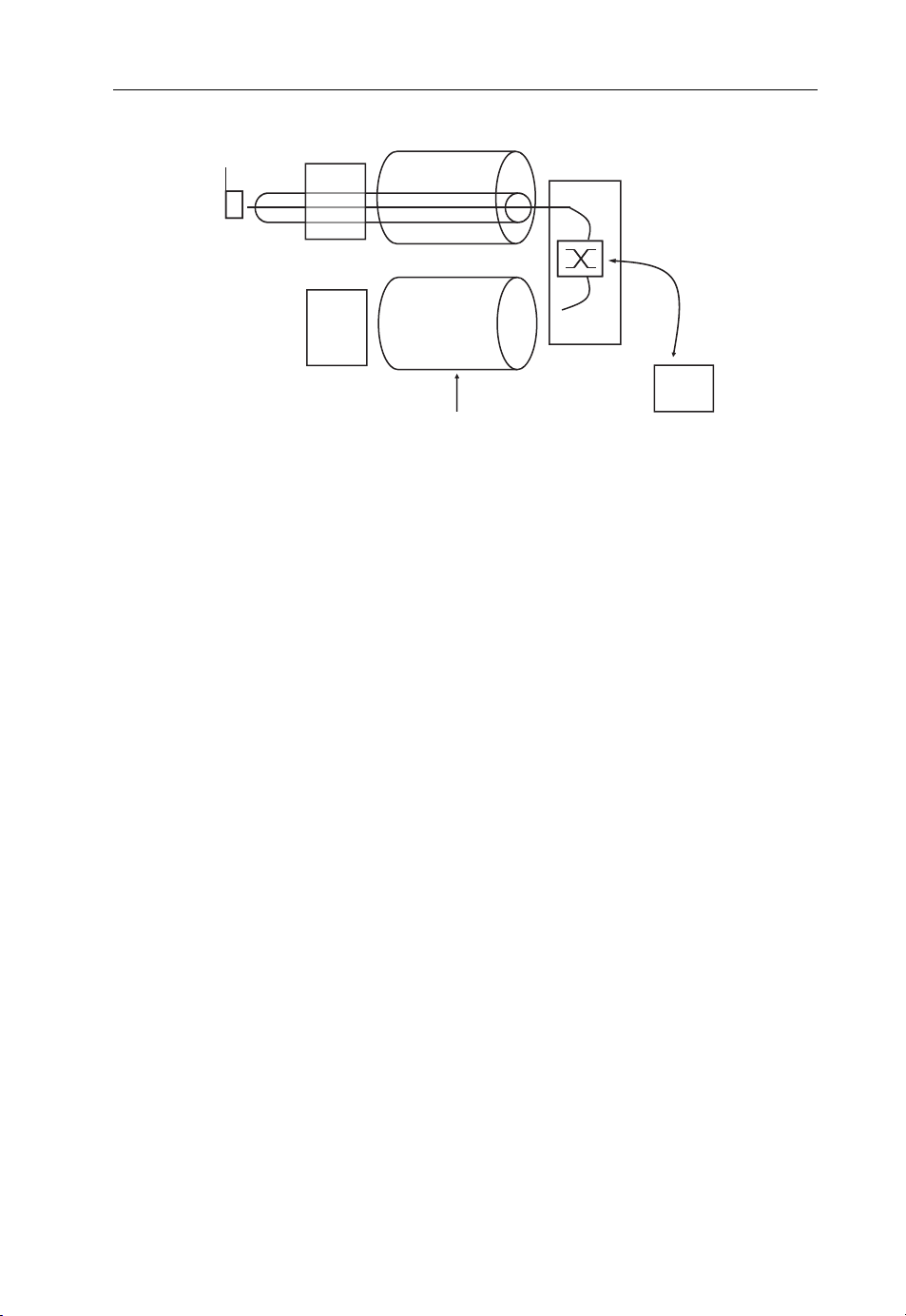
Beyond 3G Network Architectures 75
10.0.0.2
BS
195.36.219.196
BS
Figure 2.23 Base station and user tunnel for micro mobility management. (Reproduced from
Communication Systems for the Mobile Information Society, Martin Sauter, 2006, John Wiley
and Sons.)
BS tunnel
BS tunnel
10.0.0.3
R6 reference point
ASN-GW
10.0.0.1
Web
server
193.99.144.85
has been performed, the ASN-GW redirects the data flow to the tunnel between itself
(10.0.0.1) and the lower base station (10.0.0.3).
2.4.2.7 Macro Mobility Management
Like in larger UMTS and LTE networks, it is required at some point to install several
WiMAX ASN-GWs in the network to support a growing number of base stations and
users. Once there are several radio network gateways in the network, it is possible that a
user will change between cells controlled by different gateways. This means that packets
arriving for a user from the Internet can no longer only be routed by default to a single
ASN-GW. Instead, it is necessary to introduce core network mobility management as
well. In UMTS and LTE, the GPRS Tunneling Protocol (GTP) takes care of this task
between the single point of entry to the network (the GGSN in case of UMTS and the
PDN in case of LTE) and the radio access network gateway. In WiMAX, it has been
decided to use a different approach, as shown in Figure 2.24.
Instead of relying on a proprietary protocol such as GTP, it was decided to use Proxy
Mobile IP (Proxy MIP), an already existing IP-based mobility management standard [29].
In principle, Proxy MIP works as follows: when a device requests access to the network,
the ASN-GW requests an IP address for the device from the Mobile IP Home Agent. The
HA has a pool of IP addresses it is responsible for and all packets arriving from the
Internet destined to these IP addresses are always routed to the HA. From this pool, one
IP address is assigned to the device and returned to the ASN-GW. The HA notes the IP
address of the ASN-GW (64.236.23.28 in Figure 2.24) and begins forwarding all packets
arriving from the Internet to the ASN-GW. The ASN-GW in turn forw ards packets it
receives for this IP address to the base station, to which the subscriber is currently
attached via a micro mobility management tunnel as described above.
Page 86

g
76 Beyond 3G – Bringing Networks, Terminals and the Web Together
3. MIP tunnel between HA
and ASN-GW (Proxy-MIP)
MS
ASN-GW
ASN-GW
5. IP packet with
destination address
195.36.219.196
forwarded through
micro mobility
ement tunnels
mana
(195.36.219.196)
64.236.23.28
4. Care-Of IP
address (COA) is
the end point of the
tunnel
Core Network
HA
IP pool
195.36.219.196
2. address for the client
device taken from the
address pool
1. packets are
always delivered
to the HA
first
Web
server
193.99.144.85
Figure 2.24 ASN-GW mobility management using mobile IP. (Reproduced from Communication
Systems for the Mobile Information Society, Martin Sauter, 2006, John Wiley and Sons.)
For subscriber devices using IPv4, the ASN-GW terminates the MIP tunnel to make
the process transparent for the subscriber device. This is required since it is not desirable
to change the protocol stack of the device. Consequently, the ASN-GW becomes a proxy
for the subscriber’s device, which is why the approach is referred to as Proxy MIP.
For devices using only IPv6 addresses, which is expected to become more commonplace in the future, no proxy is required, as MIP is part of the protocol stack. This means
that the mobile device communicates with the HA in the network on its own instead of
leaving the task to the ASN-GW.
2.4.3 The 802.16d Air Interface and Radio Network
Like LTE,WiMAX uses Orthogonal Frequency Division Multiplexing (OFDM) to transmit
data overthe air interface. The systems are therefore very similaron the physical layer and this
section assumes the reader is familiar with the LTE air interface described in Section 2.3.3.
2.4.3.1 Fixed WiMAX
The first version of the 802.16 air interface standard, referred to as 802.16d or IEEE
802.16-2004 [30], is currently in use to connect devices such as notebooks and PCs to the
Internet via WiMAX modems inst alled at home or at the office. It is not compatible with
the current 802.16e or 802.16-2005 standards, which were developed later and introduce
many enhancements required for mobility. The lifetime and use case scenarios of fixed
WiMAX deployments are therefore limited, as devices and network equipment are
unlikely to be upgradeabl e to the mobile standard. Also , fixed WiMAX networks do
not usually use most of the standardized infrastructure described above, since their
Page 87

Beyond 3G Network Architectures 77
network architecture is much simpler and also because no support for mobility is
required. Nevertheless, this section takes a look at the fixed WiMAX air interface
standard as well, because it is used to some degree in practice and forms the basis for
mobile WiMAX, which is discussed later.
The big difference of IEEE 802.16-2004 compared with mobile WiMAX (IEEE
802.16-2005) and LTE is that it uses 256 OFDM subcarriers independent of the bandwidth used for the channel. Out of these, 193 are used for data transmissions. The
remaining subcarriers are either unused at the edge of the band or provide pilot signals
which are used by devices for channel estimation and filter approximation. Channel
bandwidths defined are 1.25, 3, 3.5, 5.5, 7 and 10 MHz. The smaller bandwidths,
however, are unlikely to be used in practice, as the resulting throughput is not sufficient
to support high-speed Internet access even for a small number of users. Using the same
number of subcarriers for all bandwidths means that the symbol transmit time varies
depending on the bandwidth. For a bandwidth of 1.25 MHz, for example, the symbol
transmit time is 128 ms, while for a 10 MHz deployment, the symbol time is only
22.408 ms. Therefore, the transmission characteristics on the physical layer depend on
the bandwidth used for a channel.
Two profiles have been defined by the WiMAX Forum for fixed WiMAX. The wireless
Metropolitan Area Network OFDM profile (wirelessMAN-OFDM) is used when a
national regulator has officially assigned a frequency band for the use of WiMAX, for
example as the outcome of a spectrum auction. Depending on the properties of the
assigned band, fixed WiMAX devices are used in either TDD or FDD mode [31].
In TDD mode, the same band is used for uplink and downlink transmissions and the
system continuously switches between transmission and reception. The advantage of this
approach is that the system can be tuned to reflect the ratio between uplink and downlink traffic. Currently, more bandwidth is required in the downlink direction, which is
why more time is allocated for downlink than for uplink transmissions. It should be
noted at this point, however, that a 3:1 downlink/uplink ratio on the air interface does
not exactly reflect the bandwidth ratio, because uplink transmissions are usually not as
efficient due to the limited output power and antenna restrictions of a small device.
Furthermore, TDD requires base stations to be tightly synchronized with each other to
prevent uplink transmissions of devices in one cell to interfere with downlink transmissions of neighboring cells.
In FDD mode, different frequency bands are used for downlink and uplink trans missions. For licensed frequency bands, this is often the preferred transmission mode. The
advantage of FDD is that data can be transmitted in uplink and downlink in parallel.
Furthermore, no transmission pause is necessary to give devices the necessary time to
switch from transmission to reception mode. In addition, FDD transmission allows more
sensitive receivers in mobile devices, which benefits overall data rates.
Figure 2.25 shows what an FDD downlink data transmission looks like in
WiMAX with the IEEE 802.16-2004 standard for stationary devices. Downlink transmissions are separated into individual frames with a fixed length between 2.5 and 20 ms.
Each frame in turn holds a number of consecutive fields. The first field is the preamble,
which has a known bit pattern that mobile devices can use to detect the beginning of a
frame. The Frame Control Header (FCH) is next and contains information about the
modulation and coding scheme of the first downlink burst that immediately follows.
Page 88
78 Beyond 3G – Bringing Networks, Terminals and the Web Together
Frame 1 Frame 2 Frame 3 Frame 4 Frame 5
Preamble FCH
Broadcast
Management
data for all
devices
Figure 2.25 WiMAX 802.16-2004 downlink data transmission. (Reproduced from Communi-
cation Systems for the Mobile Information Society, Martin Sauter, 2006, John Wiley and Sons.)
DL-Burst 1
MAC PDU MAC PDU MAC PDU MAC PDU
A packet for
client device x
DL-Burst 2 DL-Burst 3
A packet for
client device y
…
t
…
…
BPSK modulation and a 1/2 coding rate are used for the FCH to ensure that all devices
can receive the information correctly. The first downlink burst of a frame contains
downlink broadcast data at the beginning to inform devices if and at what point in the
frame data will be transmitted for them. Furthermore, the broadcast zone also contains
information for devices when they are allowed to send data in uplink direction. The
remainder of the first downlink burst of a frame then contains user data packets for one
or more devices. A frame usually contains more than a single downlink burst and each
burst can use a different mo dulation and coding scheme. The location of data for a device
thus depends on the radio condition it experiences. Figure 2.25 also shows that data is
only sent to one device at a time. This means that subscribers are only multiplexed in time
but not in the frequency domain.
As the IEEE 802.16-2004 radio interface was designed for stationary use, devices do
not report signal conditions as frequently as is required in systems supporting mobility.
Instead, it is the device’s responsibility to judge radio conditions and to send a dedicated
management message to the network to change the modulation and coding scheme for
the uplink and downlink directions when required. Likewise, error detection and correction on the MAC layer is also optional. If used for a connection, a basic Automatic
Retransmission Request (ARQ) scheme splits packages into ARQ blocks and each side
reports to the other which blocks have been received correctly. Blocks not received
correctly are then retransmitted. This mechanism is similar to that used for the
Transmission Control Protocol (TCP), which sits above the IP layer. The advantage of
additionally checking and retransmitting packets in the MAC layer is that errors can be
detected more quickly and that less data has to be retransmitted. This also helps to keep
throughput high, as TCP automatically throttles a transmission once errors occur, as it
interprets missing packets as congestion.
Page 89

Beyond 3G Network Architectures 79
2.4.4 The 802.16e Air Interface and Radio Network
As fixed wireless applications only address a limited customer base, the IEEE soon
decided after the fixed air interface standard was finalized to go one step further and to
enhance the air interface with additional functionality for mobility and for powerconstrained devices. To support mobility, the air interface management must react
quickly to changing signal conditions and it must be able to han d over a connection
between base stations when the user is moving. For battery-driven devices, the air interface had to be optimized to be as power-efficient as possible during times when no data is
being transferred. In addition, the WiMAX air interface was enhanced to allow higher
transmission speeds. The working group responsible for this task is referred to as 802.16e.
After finalization of the standard, it is now known as IEEE 802.16-2005 [32]. The mobile
WiMAX standard supports FDD and TDD, although initial deployments will only make
use of the TDD option.
2.4.4.1 Orthogonal Frequency Division Multiple Access
On the physical layer, the main difference from the fixed WiMA X standard is that the
subcarrier spacing is fixed so the number of subcarriers now varies with the bandwidth, as
shown in Table 2.2. According to [33] , the maximum channel bandwidth supported by
the first Intel WiMAX chips for notebooks is 10 MHz. In the future, however, larger
Table 2.2 Bandwidths and subcarriers for WiMAX.
Bandwidth Number of subcarriers FFT size
1.25 MHz 85 128
5 MHz 421 512
10 MHz 841 1024
20 MHz 1684 2048
bandwidths are going to be supported as well.
In addition to the parameters shown in Table 2.2, the following physical parameters
were selected:
subcarrier spacing, 10.94 kHz;
OFDM symbol duration, 91.4 ms;
cyclic prefix, 11.4 ms.
It is interesting to note that these values are similar but not identical to the values used in
LTE. In LTE, the subcarrier spacing is 15 kHz and a shorter OFDM symbol duration of
66 667 ms is used (cf. Table 2.1).
Based on these radio layer parameters , the physical layer throughput of a WiMAX cell
can be calculated as follows: The transmission time per symbol is 102.8 ms (91.4 ms for the
Page 90

80 Beyond 3G – Bringing Networks, Terminals and the Web Together
symbol itself þ 11.4 ms for the cyclic prefix), the highest modulation order is 64QAM
(6 bits per symbol) and there are 1684 subcarriers in a 20 MHz band:
Physical speed ¼ð1=0:000 102 8Þ
61684 ¼ 98 287 937 bit=s ði:e about 100 Mbit=sÞ
This is almost exactly the same value as calculated for LTE earlier in this chapter and
shows that, from this perspective, the two systems provide very similar performances.
As was described in the section on LTE, it should be noted that in practice, the
throughput of a cell is likely to be only 30–50% of this value. This is because of the
overhead for coding, retransmissions of faulty packets, pilot s ignals and the overhead
of the higher protocol layers, and also because of the less than ideal signal conditions
for most users in the cell.
Figure 2.26 shows the structure of the downlink subframe. The major difference
from the frame shown for the fixed WiMAX air interface is the fact that data
transmissions to individual users can now also be multiplexed in both time and
frequency, due to the much higher number of available subchannels. For this reason,
this form of data transmission is not referred to as OFDM (Orthogonal Frequency
Division Multiplexing) but instead as OFDMA (Orthogonal Frequency Division
Multiple Access). At the beginning of a frame, the Downlink-MAP (DL-MAP)
informs devices when and where data is scheduled for them in the frame. An optional
Uplink-MAP (UL-MAP) c an also be present in the frame to assign uplink transmission opportunities for this and the following frames.
time
FCH
User 2
DL-MAP
DL-MAP
User 1
frequency/subchannels
User 3
User 4
User 5
User 6 User 7
User n
Figure 2.26 A WiMAX OFDMA frame.
2.4.4.2 MIMO
WiMAX also supports MIMO transmissions in the downlink direction with multiple
antennas (e.g. two input, two output=2 2) in the same way as already described for
LTE. In the uplink direction, mobile devices only transmit a single data stream.
Advanced base stations, however, can activate collaborative MIMO and instruct two
devices to transmit at the same time. At the base station, the signals are recognized as
coming from different devices due to their separat e multipath characteristics and are
separated accordingly.
Page 91

Beyond 3G Network Architectures 81
Depending on transmission conditions, one of the following two different MIMO
transmission modes can be used.
Matrix A: coverage gain. In a 2 2 antenna configuration (two transmitter antennas,
two receiver antennas), a single data stream is transmitted in parallel by two separate
antennas. A mathematical algorithm known as Space Time Block Codes (STBC) is used
to encode the data streams of the two antennas to make them orthogonal to each other.
This improves the signal-to-noise ratio at the receiver, which can be used to:
increase the cell radius;
provide better throughput for subscribers that are difficult to reach (e.g. in difficult
indoor conditions or when moving at higher speeds);
transmit with higher-order modulation (e.g. 64QAM) while using fewer error correction bits, which in turn increases transmission speeds to that subscriber.
Matrix B: Capacity Increase. This flavor of MIMO, also known as Spatial Multiplexing
MIMO (SM-MIMO), sends a completely independent data stream over each antenna, as
described in previous sections. Thus, the data rate can be doubled, given that the mobile
device is close to the base station and has excellent reception conditions.
2.4.4.3 Adaptive Antenna Systems
Another feature that is already in the 802.16e standard document, but not used in early
networks, is AAS (Adaptive Antenna Systems). By using several antennas and connecting them electrically, a beam can be formed towards a client device, thus increasing the
signal-to-noise ratio experienced by the client device. To form a beam, the signal is sent
over each antenna with a calculated phase shift and amplitude relative to the other
antennas. There are no moving parts required for directing the beam in a certain
direction, as the beam-forming effect is based on the phase and amplitude differences
of the signals. Beamforming can be used in both the uplink and the downlink. For the
uplink, beamforming improves the reception of the signal from a device and in the
downlink beamforming lowers interference for other devices receiving a transmission
from a neighboring cell on the same frequency.
2.4.4.4 Handover Procedures
In 802.16e, both the mobile station and the network can initiate a handover procedure.
This is different from UMTS and LTE, in which a handover of a connection is always
initiated by the network. In the IEEE specification, a handover is sometimes also referred
to as a cell resel ection. This is somewhat unfortunate since in other systems cell reselection is the process to change to another cell while no connection is established to the
network.
To perform a handover to a new cell, a mobile has to search for neighboring cells when
signal conditions deteriorate. During this process, the mobile will not be able to receive
data from the current cell. For this reason, the mobile and base station have to agree
when such searches can be performed and the base station then buffers all incoming data
Page 92

82 Beyond 3G – Bringing Networks, Terminals and the Web Together
packets until the mobile device is back and receiving incoming data. When neighboring
cells are detected by the mobile. it reports the reception conditions detected to the
network via the serving base station. Both the network and the mobile can then initiate
a handover procedure, if required. The mobile device on the one hand can initiate the
handover if it feels that it would get better service from a neighboring cell. The network
on the other hand can initiate a handover for the same reason or for load balancing
purposes if it detects that a neighboring cell with less traffic can be received equally well
by the device as the current cell.
In the simplest handover variant, the network or the mobile initiates a handover, which
causes a short service interruption while the mobile connects to the new cell. If it is
already synchronized, the outage will be shorter than if the mobile first has to associate to
the cell and the new cell has to request the subscriber’s current parameters from the
previous cell.
For real-time services such as VoIP, interruptions are undesired and two further
options have been standardized to improve the handover behavior. The first optional
procedure is referred to as Fast Base Station Switching (FBBS). As in the basic approach
above, the base station requests the mobile to frequently scan for the availability of
neighboring cells. These a re then reported to the serving base station. If signal conditions
are strong enough, the serving base station contacts the neighboring base station via the
backhaul connection and requests them to set up a context for this subscriber. If the base
stations agree, the mobile device is informed that it can select from which base station it
wants to receive its downlink data packets. The base stations are kept in a diversity list
(the active set) in the mobile which can, by sending a short command, instruct the
network to change the cell for downlink transmission. This way, the mobile can quickly
react to changing signal conditions. In uplink direction, all base stations that are part of
the active set receive the data stream from the mobile and forward correct ly received
packets to the ASN-GW. This increases the probability that the network receives at least
one copy of each packet but has the disadvantage of increasing bandwidth requirements
on the backhaul links.
The Macro Diversity Handover (MDHO) is an even smoother form of handover.
Here, all base stations in the active set transmit frames on the downlink to the subscriber.
The mobile can then combine the received signal and thus increase the chance of
successfully receiving a packet. This approach is quite similar to the UMTS soft handover, which, however was abandoned again with HSPA and LTE as it was seen as too
costly in terms of capacity requirements on the air interface and the backhaul connection.
Both FBBS and MDHO require that all cells that are part of the handover procedure use
the same frequency, as the mobile only has a single transceiver and can therefore only
receive and transmit on a single frequency.
2.4.4.5 Power Saving and Idle Mode
To minimize the power requirements of battery-driven devices, mobile WiMAX introduces a number of power-saving modes, referred to in the standard as power-saving
classes. With power-saving class 1 the mobil e and network agree on a pattern in which the
device periodically listens to the downlink and afterwards enters sleep mode for some
time, during which it cannot be reached. Over time, the sleep periods are automatically
Page 93

Beyond 3G Network Architectures 83
extended as it becomes less likely that data arrives for the device. Should data arrive while
a mobile is in the sleep state, it is buffered in the base station and sent to the mobile as
soon as it reactivates its transceiver. This automatically ends the power-save mode.
Power save mode is also left when the mobile sends data on the uplink.
While this power-save mode is suitable for bursty data traffic with applications such as
Web browsing, it is less suitable for VoIP transmissions, which also have long but
predictable periods of inactivity between two packets. Here, it would not make sense to
enter or exit power-save mode every time a packet has to be sent or received. Power-saving
class 2 thus limits data transmissions to certain intervals. Outside these intervals, the device
can turn off its transmitter. In practice, this limits the bandwidth available to a device,
which is quite acceptable for VoIP applications that require little bandwidth anyway.
Finally, with power-saving class 3, the network and mobile can agree on a single sleep
period after which the connection automatically becomes active again.
In practice, several service flows, each with a different IP address and for different
applications, can be active per device. Each service flow can be in a different powersaving mode. The transmitter is then only switched off at times in which all service flows
have entered a power-saving state.
2.4.4.6 Idle Mode
Even while in a power-save mode, a mobile device is required to wake up periodically and
communicate with the network. In cases of long inactivity, this is undesired as it requires
resources on the network side to keep a connection active and has a negative impact on
the overall standby time of the device. The standard therefore also defines an idle mode
state, in which the radio connection to the network is removed, while the device still keeps
its IP address(es). Once in idle mode, the mobile can switch off its transceiver and only
occasionally check the reception level of the current and neighboring cells and to observe
incoming paging messages which could announce waiting packets on the network side.
The paging interval is usually in the order of a few seconds. Another advantage of being
in idle mode is that the mobile device can roam between different cells of the network that
are in the same paging group without reporting the location change to the network. Only
if the mobile roams to a cell in a different paging group does it have to inform the network
of its new location, that is of its new paging group, so paging messages can be sent to the
new paging group in the future. As a paging is sent via several cells, paging coordination
is a task of the ASN-Gateway.
2.4.5 Basic Procedures
Figure 2.27 shows the basic procedures to establish a connection with the network after a
mobile device has been powered on. In the first step, it will try to find the previously used
network, whose parameters it might have saved in nonvolatile memory. Use of this
information has the advantage that the mobile can go directly to a certain frequency
and, if the user has not moved since the device was switched off, is very likely to receive a
signal instantly. If the user has moved and no signal is found, a standard network search
procedure is started. At first, downlink transmissions of a network are detected by
searching for the preamble of each frame which has a known bit pattern. Once the
Page 94

k
84 Beyond 3G – Bringing Networks, Terminals and the Web Together
Mobile Device Networ
1. Synchronization
2. Ranging
3. Capability Information Exchange
4. Authentication
5.Network Registration
6. Service Flow Creation
Connection established, user data can now be exchanged
Figure 2.27 Stages required to connect to a WiMAX network.
preamble is detected, the mobile device is synchronized to the frame structure of the
downlink transmissions and can start to receive and decode cell information, which is
sent after the frame’s preamble.
The cell information describes, among other things, where to find the contention-based
ranging area, which is used in the second step to get into contact with the network. This
area, referred to in other standards as the random access channel, is then used by the device
to send a ranging request message with a low power level. The message includes the MAC
hardware address of the device and the modulation and coding scheme the device suggests
the network use to send an answer. If no answer is received, the message is repeated with a
higher transmission power. Once the network has successfully received the ranging request,
it answers with a ranging response message. The message contains information on how the
device has to adjust its power lever for further communication and its synchronization.
Synchronization corrections are required as the mobile station is not aware of the distance
to the base station. The more distant it is from the base station, the earlier it has to send its
transmissions to arrive in synch with packets of other subscribers that have different
distances from the base station. The mobile device applies these values and sends another
ranging request to the network. The network verifies that the values have been applied
correctly and then returns a ranging response message, confirming the procedure and
including Connection IDs (CIDs) that will identify packets to the mobile device in the
downlink direction and bandwidth grants in the uplink direction.
In the third step, the mobile device sends a capability request message to the network
which contains information about its capabilities such as the supported modulation and
coding schemes. The network answers with a capability response message which
contains its own capabilities. Capability exchange messages are not transmitted in the
Page 95

Beyond 3G Network Architectures 85
contention-based area, but with the basic CID as part of the data area of a frame. This
means that, as soon as the network has sent a final range response message, it starts to
schedule uplink resourc es for the mobile device.
In step 4, the device and network authenticate each other as described in Section 2.4.2.
Afterwards, the mobile registers to the network. Once registered, the final step in
Figure 2.27 consists of establishing a service flow and dedicated CIDs for the user
data. This procedure can be initiated by the mobile device or the network, where the
service flow is pre-provisioned. Since service flows are agnostic to higher-layer protocols,
no IP address is assigned at this point. This is a separate action, which has to be
performed by the device once the service flow is active by sending a DHCP (Dynamic
Host Configuration Protocol) request to the network in a similar way as is done today in
fixed Ethernet and Wi-Fi networks.
2.4.6 Summary and Comparison with HSPA and LTE
When comparing the physical parameters of WiMAX, LTE and HSPAþ, it becomes
apparent that in a 5 MHz band, performance of the three systems is very similar. Beyond
a bandwidth of 5 MHz, LTE and WiMAX perform on a similar level, as both use OFDM
modulation and very similar radio parameters. The major difference between the two is
that WiMAX will first be deployed in TDD mode, while LTE will mainly be used in FDD
mode for historical reasons. Another difference is that LTE uses a different uplink
scheme, making it more power-efficie nt. How much difference this will make in practice
remains to be seen. All other differences between the two systems are in the higher layers
in the system. While the LTE air interface has inherited a strict channel structure from
UMTS, the WiMAX air interface design is much simpler and adheres more to the simple
Ethernet-style based MAC layers.
In practice, achievable transmission speed is just one of several important parameters. Equally important is how well a system is able to handle potentially
hundreds of always-on devices per cell, each communicating with the system several
times a minute, as applications such as VoIP, encrypted VPN ( Virtual Private
Network) tunnels and instant messengers constantly communicate with their servers
in the network to keep their channels open through firewalls and NAT gateways.
This requires that the system is not only streamlined for high bandwidths but to
also able to handle a significant number of bandwidth requests per second for the
keep alive messaging without sacrificing bandwidth and mobile battery power. As
can be seen with HSPA, air interfaces are continuously enhanced to also take this
issue into account. It therefore remains to be seen how first WiMAX and LTE
networks fare in this regard and how their evolution accommodates such device
behavior. As a consequence of this continuing evolution, it is impossible to describe
one system as better than another in terms of performance.
2.4.6.1 Good Competition Between Network Technologies
Since LTE and HSPA on the one hand and WiMAX on the other are very similar in terms
of through put and usage scenarios, many observers raise the question of whether we will
Page 96

86 Beyond 3G – Bringing Networks, Terminals and the Web Together
see a similar destructive competition as in the days of the 2G GSM and CDMA networks.
Here, users and operator s did not benefit greatly from this competition because
networks and applications were both in the hands of the operators. This created many
incompatibility issues for users. One example is text messaging. While in Europe, text
messaging has flourished for a long time, it has only recently become popular in the USA.
The main reason for this was that it was not possible for users of different networks to
exchange text messages. Thus, the service did not take off until interoperability was
finally introduced.
With HSPA, LTE and WiMAX, however, the application landscape is quite
different. Here, the networks and applications are separated and do not depend
on each other. Applications are based on the Internet Protocol and use w hatever
network is available. Internet Protocol applications are not and should not be
aware of the underlying network technology, which allows people to develop
applications independently of the wireless network architecture. Some applications
will still be developed by operators but the vast majority will come from Internetbased companies, as will be shown in more detail in Chapter 6. As a result of this
split between the application and the network, the competition between different
wireless technologies becomes very beneficial because:
It encourages faster network roll outs, as this is one of the few differentiators between
network operators.
It offers possibilities for new player s in the market.
It creates competition between device manufacturers.
New applications can be introduced much more easily and quickly, as they are no
longer forced into a tight network operator controlled framework.
2.4.7 802.16m: Complying with IMT-Advanced
Like LTE, WiMAX is also set to compete for a place in IMT-Advanced 4G. As the
current specification is also not likely to qualify for 4G, several activities have been
started to enhance the system. The 802.16m working group has been tasked to specify an
air interface with a higher bitrate and the following enhancements are foreseen to
improve system performance [34].
2.4.7.1 Use of Several Car riers
Like other standards bodies, the IEEE has recognized that increasing the bandwidth used
for data transmission is one of the best ways to increa se overall data transfer rates.
A multicarrier approach, in which two or even more carriers are used for transferring
data, will be used by the future WiMAX air interface. The approach used by WiMAX is
backwards-compatible, that is 802.16e and 802.16m mobile devices can be served by
the same base station on the same carrier. An 802.16e device, however, does not see the
channel bundling and continues to use only one carrier. To be backwards-compatible,
high-speed zones are introduced in a frame, which are only available for 802.16m devices.
If the carriers used for transmission are adjacent, guard bands that are normally in place
to separate the carriers can be used for transferring data.
Page 97

Beyond 3G Network Architectures 87
2.4.7.2 Self Organization and Inter Base Station Coordination
Interference from neighboring base stations and mobile devices is undesirable in wireless
systems, as it reduces the overall system throughput. The new version of the standard
introduces methods and procedures to request mobile devices to perform interference
measurements at their location and send them back to the base station. The base station
can then use the information gathered from different devices to adjust its power settings
and potentially also to coordinate the frequency use with neighboring base stations.
2.4.7.3 New Frame Structure
In practice, it has been observed that the 802.16e frame structure with frame lengths of up
to 20 ms is too inflexible. The downside of such long frames is slow network access and
slow repetition of faulty data blocks, as devices only have one transmission opportunity
per frame. The standard 802.16 m uses a new frame structure which consists of superframes (20 ms) which are further divided into frames (5 ms) and again divided into eight
subframes (0.617 ms). Within each frame of 5 ms, the transmission direction can be
changed once. Since eight subframes fit into a frame, downlink/uplink time allocations
of 6/2, 5/3, and so on can be achieved. By switching the transmission direction at least
every 5 ms, HARQ retransmission delays are cut by three-quarters, the idle-to-active
state transmission time is reduced from above 400 ms to less than 100 ms and the one-way
access delay is reduced from almost 20 ms to less than 5 ms [34].
2.4.8 802.16j: Mobile Multihop Relay
In many scenarios, especially in rural areas, there are often only few or no possibilities at
all to backhaul high-bandwidth connections via a fixed line copper or fiber links.
Consequently, cells need to be connected wirelessly to the network either over highbandwidth microwave links or via a concept in which the base stations themselves form a
mesh-like network to forward traffic between base stations with no dedicated backhaul
connection. WiMAX is the first standard to incorporate such a backhaul method and the
802.16j working group specifies how this should work in practice [35].
In addition to rural backhau ling, forwarding traffic between wireless network nodes is
also an interesting method to fill coverage holes and to improve in-building coverage. At
first, it might seem illogical that sending a data packet over the air interface more than
once actually increases the data rate. In practice, however, transmitting the packet over
two or more links with a high signal-to-noise ratio is better than only transmitting it once
but very slowly over a low-quality channel.
The 802.16j amendment to the standard, also referred to as Mobile Multih op Relay
(MMR), covers the following points to achieve these goals without increasing the
number of base stations with expensive backhaul links:
2.4.8.1 Backwards Compatibility
MMR has been specified in a way that does not require mobile devices to be aware of
relay nodes. This is important as introducing relaying would otherwise not be possible in
already deployed networks.
Page 98

88 Beyond 3G – Bringing Networks, Terminals and the Web Together
2.4.8.2 Multihop Capability
The standard is designed in a way that allows packets to traverse several hops to and from
a base station that has a backhaul connection.
2.4.8.3 Relay Station Implementation Options
From the point of view of mobile devices, relays without a dedicated backhaul connection look like a standard base station and have their own base station ID. The specification defines two kinds of Relay Stations (RS). A simple RS behaves almost like a simple
repeater and leaves most of the work to a real base station, including even the handling of
simple messages such as ranging requests. Such simple relays are also referred to as
transparent relays as all links to mobile devices via relay stations are controlled by a base
station. More complex relays, referred to as nontransparent relays, are able to locally
manage the link to the subscriber and only forward user data packets to a base station
and higher layer signaling information.
2.5 802.11 Wi-Fi
2.5.1 Introduction
At the end of the 1990s the first devices appeared on the market using a new wireless local
area network technology that is commonly referred to today as Wireless LAN or Wi-Fi.
Wi-Fi is specified by the IEEE in the 802.11 standard. It is very similar to the 802.3 fixed
line Ethernet standard and reuses all protocol layers down to layer 2, as shown in
Figure 2.28. The major difference between the two protocols is on layer 1, where the
fixed line medium access has been replaced with several wireless variants. Furthermore,
some additional management features were specified that address the specific needs of
wireless transmissions that do not exist in fixed line networks, such as network announcements, automatic packet retransmission, authentication procedures and encryption.
Over the years, several physical layer standards were added to increase transmission
speeds and to introduce additional features. Devices are usually backwards-compatible
and support all previous standards to enable newer and older devices to communicate
with each other.
5–7
4
3
2
802.3
1
(Ethernet)
Figure 2.28 The 802.11 protocol stack. (Reproduced from Communication Systems for the Mobile
Information Society, Martin Sauter, 2006, John Wiley and Sons.)
Application specific
TCP/UDP
IP
802.2 Logical Link Control (LLC)
802.11b 802.11g
802.11a
802.11n
Page 99

Beyond 3G Network Architectures 89
Initially, Wi-Fi was not very popular or widely known as network interface cards were
expensive and transmission speeds ranged between 1 and 2 Mbit/s. Things changed
significantly with the introduction of 802.11b, which specified a physical layer for
transmission speeds of up to 11 Mbit/s. Network interface cards became cheaper and
devices appeared that could be connected to PCs and notebooks over the new high-speed
USB (Universal Serial Bus) interface. Prices fell significantly and Intel decided to include
Wi-Fi capabilities in their ‘Centrino’ notebook chipsets. At the same time, the growing
popularity of high-speed DSL and TV cable Internet connectivity made wireless networking more interesting to consumers, since the telephone or TV outlet was and still is
often not close to where a PC or notebook is located. Wi-Fi was the ideal solution to this
problem and Wi-Fi access points were soon integrated into DSL and cable modems.
Likewise, Internet access in public places such as cafes, hotels, airports and so on became
popular, again enabled by Wi-Fi and cheap high-speed Internet access at the other end of
the wireless connection via DSL. Today, Wi-Fi has become ubiquitous in notebook s and
many other mobile and portable devices such as game consoles, mobile phones, Internet
tablets and Mobile Internet Devices (MID).
Over time, two additional physical layer specifications were added to further increase
transmission speeds. The 802.11g standard increased data transfer speeds to up to
54 Mbit/s on the air interface, and the recent 802.11n standard has the potential for up
to 300 Mbit/s. It should be noted at this point that these speeds are only theoretical and
not measured on the air interface. In practice, protocol overhead reduces the achievable
speeds at the application layer to about half those values. This is discussed in more detail
in the following sections. Standard 802.11a is another Wi-Fi air interface variant, but has
never gained much popularity because it does not use the same standard frequency band
as the other 802.11 variants.
The remainder of this chapter is structured as follows: as a first step, the Wi-Fi network
infrastructure model is discussed. This is followed by an introduction to the different
physical layers and their properties. Like other wireless networking technologies, the
network needs to be managed and organized and basic management procedures are
discussed next. Wi-Fi security is a very important topic and, as initially encryption
algorithms were found to be insecure, it is worth taking a look at this topic and discussing
how security was improved over time. Due to the tremendous popularity of Wi-Fi and
the growing use of the technology for real-time applications such as VoIP and video
streaming, quality of service is becoming an important topic. As a consequence, this
chapter then discusses the QoS extension of the Wi-Fi standard and how it can improve
reliability for such applications.
2.5.2 Network Architecture
2.5.2.1 The Wireless Network in a Box
Unlike the network technologies described before, Wi-Fi is foremost a local area networking technology and most Wi-Fi networks are deployed as a ‘network in a box’ as
shown in Figure 2.29. In a typical home network, the Wi-Fi network bridges the final
meters between the DSL modem and the devices using the fixed line Internet connection.
The Wireless LAN Access Point (AP) is usually combined with the DSL modem and also
Page 100

90 Beyond 3G – Bringing Networks, Terminals and the Web Together
Multi purpose WLAN Access Point
WLAN
Access Point
Ethernet
10 Mbit/s–1 GBit/s
Ethernet Switch
(Layer 2)
Wireline Ethernet devices
Figure 2.29 A DSL router with a wireless LAN interface. (Reproduced from Communication
Systems for the Mobile Information Society, Martin Sauter, 2006, John Wiley and Sons.)
(internal)
DHCP
Server
IP Router
with NAT
(Layer 3)
Ethernet PPPoE
DSL
Modem
To DSL Splitter
serves as the DHCP server, which provides network configuration parameters such as the
IP address to notebooks and other wireless devices when they connect to the network.
Most multipurpose DSL or cable routers also have a built-in Ethernet switch with several
ports to connect PCs and other devices with a twisted-pair Ethernet cable.
2.5.2.2 Network Address Translation
Multipurpose routers such as the WLAN access point can connect many wireless and
wired clients to the network; they usually also include NAT functionality, that separates
the local network from the DSL connection and translates IP addresses between the LAN
and the WAN. This translation is required because the Internet service provider’s network
usually only assigns a single IP address per DSL connection. By using NAT, local IP
addresses and TCP or UDP port numbers are mapped to the external IP address and the
same or different TCP or UDP port numbers. This allows all local devices to communicate
with servers on the Internet simultaneously via separate connections. From an external
network point of view, all devices use the same IP address. While this works well for many
applications, there are some for which this translation creates a problem, as incoming
packets are discarded if they do not belong to a mapping that was created by an outgoing
packet first. This can be solved by configuring static mappings, which forward incoming
packets for a server (e.g. a Web server) to a specific internal IP address.
Static mappings, however, are only useful for servers that always use the same TCP or
UDP port numbers. SIP, however, which is the dominant protocol for VoIP applications,
uses dynamic port numbers. In addition, SIP applications use an IP address they can
query from the local protocol stack and include it in application layer messages. As the
local network stack is not aware of the external IP address assigned by the DSL
 Loading...