

Page 1

BACKHAULING/
FRONTHAULING FOR
FUTURE WIRELESS
SYSTEMS
www.ebook3000.com
Page 2

BACKHAULING/
FRONTHAULING FOR
FUTURE WIRELESS
SYSTEMS
Edited by
Kazi Mohammed Saidul Huq and Jonathan Rodriguez
Instituto de Telecomunicações, Aveiro, Portugal
www.ebook3000.com
Page 3

This edition first published 2017
© 2017 John Wiley & Sons, Ltd.
Registered Office
John Wiley & Sons, Ltd, The Atrium, Southern Gate, Chichester, West Sussex, PO19 8SQ, United Kingdom
For details of our global editorial offices, for customer services and for information about how to apply for permission to
reuse the copyright material in this book please see our website at www.wiley.com.
The right of the author to be identified as the author of this work has been asserted in accordance with the Copyright,
Designs and Patents Act 1988.
All rights reserved. No part of this publication may be reproduced, stored in a retrieval system, or transmitted, in any form
or by any means, electronic, mechanical, photocopying, recording or otherwise, except as permitted by the UK Copyright,
Designs and Patents Act 1988, without the prior permission of the publisher.
Wiley also publishes its books in a variety of electronic formats. Some content that appears in print may not be available in
electronic books.
Designations used by companies to distinguish their products are often claimed as trademarks. All brand names and product
names used in this book are trade names, service marks, trademarks or registered trademarks of their respective owners.
The publisher is not associated with any product or vendor mentioned in this book.
Limit of Liability/Disclaimer of Warranty: While the publisher and author have used their best efforts in preparing this
book, they make no representations or warranties with respect to the accuracy or completeness of the contents of this
book and specifically disclaim any implied warranties of merchantability or fitness for a particular purpose. It is sold
on the understanding that the publisher is not engaged in rendering professional services and neither the publisher nor
the author shall be liable for damages arising herefrom. If professional advice or other expert assistance is required, the
services of a competent professional should be sought
Library of Congress Cataloging‐in‐Publication Data
Names: Huq, Kazi Mohammed Saidul, editor. | Rodriguez, Jonathan, editor.
Title: Backhauling/fronthauling for future wireless systems / edited by Kazi Mohammed Saidul Huq,
Jonathan Rodriguez.
Description: Chichester, UK ; Hoboken, NJ : John Wiley & Sons, 2017. |
Includes bibliographical references and index.
Identifiers: LCCN 2016026831 (print) | LCCN 2016042959 (ebook) | ISBN 9781119170341 (cloth) |
ISBN 9781119170358 (pdf) | ISBN 9781119170365 (epub)
Subjects: LCSH: Wireless communication systems.
Classification: LCC TK5103.2 .B33 2017 (print) | LCC TK5103.2 (ebook) | DDC 384.5–dc23
LC record available at https://lccn.loc.gov/2016026831
A catalogue record for this book is available from the British Library.
Cover image: Gettyimages/Petrovich9
Set in 11/13pt Times by SPi Global, Pondicherry, India
10 9 8 7 6 5 4 3 2 1
www.ebook3000.com
Page 4

Contents
List of Contributors ix
Preface xi
Acknowledgements xiii
1 Introduction: The Communication Haul Challenge 1
Kazi Mohammed Saidul Huq and Jonathan Rodriguez
1.1 Introduction 1
References 7
2 A C‐RAN Approach for5G Applications 9
Kazi Mohammed Saidul Huq, Shahid Mumtaz and Jonathan Rodriguez
2.1 Introduction 9
2.2 From Wired toWireless Backhaul/Fronthaul Technologies 11
2.3 Architecture forCoordinated Systems According
toBaseline 3GPP 12
2.4 Reference Architecture forC‐RAN 15
2.4.1 System Architecture forFronthaul‐based C‐RAN 15
2.4.2 Cloud Resource Optimizer 16
2.5 Potential Applications forC‐RAN‐based Mobile Systems 20
2.5.1 Virtualization ofD2D Services 20
2.5.2 Numerical Analysis 21
2.6 Conclusion 24
References 27
3 Backhauling 5G Small Cells withMassive‐MIMO‐Enabled
mmWave Communication 29
Ummy Habiba, Hina Tabassum and Ekram Hossain
3.1 Introduction 29
3.2 Existing Wireless Backhauling Solutions for5G Small Cells 31
3.3 Fundamentals ofmmWave andMassive MIMO Technologies 32
3.3.1 MmWave Communication 32
3.3.2 MU‐MIMO withLarge Antenna Arrays 33
www.ebook3000.com
Page 5

vi Contents
3.4 MmWave Backhauling: State oftheArt andResearch Issues 34
3.4.1 LOS mmWave Backhauling 35
3.4.2 NLOS mmWave Backhauling 36
3.4.3 Research Challenges forBackhauling in5G Networks 37
3.5 Case Study: Massive‐MIMO‐based mmWave BackhaulingSystem 40
3.5.1 System Model 41
3.5.2 Maximizing User Rate 44
3.5.3 Matching Theory forUser Association 45
3.5.4 Numerical Results 48
3.6 Conclusion 51
Acknowledgement 51
References 51
4 Fronthaul foraFlexible Centralization inCloud Radio Access Networks 55
Jens Bartelt,
Dirk Wübben, Peter Rost, Johannes Lessmann andGerhardFettweis
4.1 Introduction 55
4.2 Radio Access Network Architecture 57
4.3 Functional Split Options 58
4.4 Requirements ofFlexible Functional Splits 60
4.4.1 Split A 61
4.4.2 Split B 62
4.4.3 Split C 63
4.4.4 Split D 64
4.4.5 Summary andExamples 64
4.5 Statistical Multiplexing inaFlexibly Centralized Network 67
4.5.1 Distribution ofFH Data Rate per Base Station 67
4.5.2 Outage Rate 68
4.5.3 Statistical Multiplexing onAggregation Links 69
4.6 Convergence ofFronthaul andBackhaul Technologies 73
4.6.1 Physical Layer Technologies 73
4.6.2 Data/MAC Layer Technologies 75
4.6.3 Network Layer Technologies 77
4.6.4 Control andManagement Plane 78
4.7 Enablers ofaFlexible Functional Split 78
4.8 Summary 80
Acknowledgement 82
References 82
5 Analysis andOptimization forHeterogeneous Backhaul Technologies 85
Gongzheng Zhang, Tony Q. S. Quek, Marios Kountouris, Aiping Huang
andHangguan Shan
5.1 Introduction 85
5.2 Backhaul Model 88
5.2.1 Network Model 88
www.ebook3000.com
Page 6

Contents vii
5.2.2 Delay Model 89
5.2.3 Cost Model 92
5.3 Backhaul Packet Delay Analysis 93
5.3.1 Mean Backhaul Packet Delay 93
5.3.2 Delay‐limited Success Probability 95
5.3.3 Performance Evaluation 97
5.4 Backhaul Deployment Cost Analysis 101
5.5 Backhaul‐aware BS Association Policy 103
5.5.1 Mean Network Packet Delay 103
5.5.2 BS Association Policy 107
5.5.3 Numerical Results 109
5.6 Conclusions 115
References 115
6 Dynamic Enhanced Inter‐cell Interference Coordination
StrategywithQuality ofService Guarantees for
Heterogeneous Networks 119
Wei‐Sheng Lai, Tsung‐Hui Chang, Kuan‐Hsuan Yeh and Ta‐Sung Lee
6.1 Introduction 119
6.2 System Model andProblem Statement 121
6.2.1 Network Environments 121
6.2.2 QoS Constraint 124
6.2.3 Problem Statements 125
6.3 Dynamic Interference Coordination Strategy 126
6.3.1 SMDP Analysis 126
6.3.2 Admission Control withaQoS Constraint 128
6.3.3 Joint Dynamic eICIC andAdmission Control for
SumRateMaximization 129
6.3.4 Joint Dynamic eICIC andAdmission Control for
ProportionalFairness Maximization 130
6.4 Numerical Results 132
6.5 Conclusion 140
References 140
7 Cell Selection forJoint Optimization oftheRadio Access
and Backhaul inHeterogeneous Cellular Networks 143
Antonio De Domenico, Valentin Savin and Dimitri Ktenas
7.1 Introduction 143
7.2 System Model andProblem Statement 145
7.2.1 Joint RAN/BH Capacity 146
7.2.2 Problem Statement 151
7.3 Proposed Solutions 151
7.3.1 Evolve 151
7.3.2 Relax 154
7.3.3 Practical Implementation oftheProposed Algorithms 156
www.ebook3000.com
Page 7

viii Contents
7.4 Simulation Results 157
7.5 Conclusion 165
References 165
8 Multiband andMultichannel Aggregation forHigh‐speed Wireless
Backhaul: Challenges andSolutions 167
Xiaojing Huang
8.1 Introduction 167
8.2 Spectrum forWireless Backhaul 170
8.2.1 Microwave Band andChannel Allocation 170
8.2.2 Millimetre‐wave Band andUsage Trend 171
8.3 Multiband andMultichannel Aggregation 172
8.3.1 Band andChannel Aggregation Overview 172
8.3.2 System Architecture 174
8.3.3 Subband Aggregation andImplementations 177
8.3.4 Full SDR Approach forBand andChannel Aggregation 183
8.4 Spectrally Efficient Channel Aggregation 185
8.4.1 System Overview 185
8.4.2 Frequency‐domain Multiplexing Without aGuard Band 186
8.4.3 Digital IF Signal Generation andReception 188
8.4.4 High-performance OFDM Transmission 188
8.5 Practical System Examples 189
8.5.1 CSIRO Ngara Backhaul 190
8.5.2 CSIRO High‐speed E‐band Systems 191
8.6 Conclusions 194
References 194
9 Security Challenges forCloud Radio Access Networks 195
Victor Sucasas, Georgios Mantas and Jonathan Rodriguez
9.1 Introduction 195
9.2 Overview ofC‐RAN Architecture 196
9.3 Intrusion Attacks intheC‐RAN Environment 197
9.3.1 Entry Points forIntrusion Attacks 198
9.3.2 Technical Challenges forIntrusion Detection
Counter‐mechanisms 201
9.3.3 Insider Attacks 203
9.4 Distributed Denial ofService (DDoS) Attacks Against C‐RAN 205
9.4.1 DDoS Attacks Using Signalling Amplification 206
9.4.2 DDoS Attacks Against External Entities Over
the Mobile Network 207
9.4.3 DDoS Attacks fromExternal Compromised IP Networks
OvertheMobile Network 208
9.5 Conclusions 209
References 209
Index 213
www.ebook3000.com
Page 8

List of Contributors
Jens Bartelt
Technische Universität Dresden, Vodafone Chair MNS, Dresden, Germany
Tsung-Hui Chang
School of Science and Engineering, The Chinese University of Hong Kong,
Shenzhen,CUHK (SZ), China
Antonio De Domenico
CEA, LETI, MINATEC, Grenoble, France
Gerhard Fettweis
Technische Universität Dresden, Vodafone Chair MNS, Dresden, Germany
Ummy Habiba
The Department of Electrical and Computer Engineering, University of Manitoba,
Canada
Ekram Hossain
The Department of Electrical and Computer Engineering, University of Manitoba,
Canada
Aiping Huang
College of Information Science and Electronic Engineering, Zhejiang University,
China
Xiaojing Huang
Faculty of Engineering and Information Technology, University of Technology
Sydney (UTS), Australia
Kazi Mohammed Saidul Huq
Instituto de Telecomunicações, Aveiro, Portugal
Marios Kountouris
Mathematical and Algorithmic Sciences Lab, France Research Centre, Huawei
Technologies, France
Dimitri Ktenas
CEA, LETI, MINATEC, Grenoble, France
www.ebook3000.com
Page 9

x List of Contributors
Wei-Sheng Lai
Department of Electrical and Computer Engineering, National Chiao Tung
University, Hsinchu, Taiwan
Ta-Sung Lee
Department of Electrical and Computer Engineering, National Chiao Tung
University, Hsinchu, Taiwan
Johannes Lessmann
NEC Laboratories Europe, Heidelberg, Germany
Georgios Mantas
Instituto de Telecomunicações, Aveiro, Portugal
Shahid Mumtaz
Instituto de Telecomunicações, Aveiro, Portugal
Tony Q. S. Quek
Information Systems Technology and Design Pillar, Singapore University of
Technology and Design, Singapore
Jonathan Rodriguez
Instituto de Telecomunicações, Aveiro, Portugal
Peter Rost
Nokia Networks, Munich, Germany
Valentin Savin
CEA, LETI, MINATEC, Grenoble, France
Hangguan Shan
College of Information Science and Electronic Engineering, Zhejiang University,
China
Victor Sucasas
Instituto de Telecomunicações, Aveiro, Portugal
Hina Tabassum
The Department of Electrical and Computer Engineering, University of Manitoba, Canada
Dirk Wübben
University of Bremen, Department of Communications Engineering, Bremen, Germany
Kuan-Hsuan Yeh
ASUSTeK Computer Inc., Taipei, Taiwan
Gongzheng Zhang
College of Information Science and Electronic Engineering, Zhejiang University,
China
www.ebook3000.com
Page 10

Preface
In a mobile communication system, the segment that connects the core to the access
networks is termed the ‘backhaul’. The edges of any telecommunication network are
connected through backhauling. The importance of backhaul research is spurred by
the need for increasing data capacity and coverage to cater for the ever‐growing
population of electronic devices–smartphones, tablets and laptops–which is foreseen to hit unprecedented levels by 2020. The backhaul is anticipated to play a critical
role in handling large volumes of traffic, its handling capability driven by stringent
demands from both mobile broadband and the introduction of heterogeneous networks
(HetNets). Backhaul technology has been extensively investigated for legacy mobile
systems, but is still a topic that will dominate the research arena for next generation
mobile systems; it is clear that without proper backhauling, the benefits introduced by
any new radio access network technologies and protocols would be overshadowed.
Traditionally, the backhaul segment connects the RAN (radio access network) to
the rest of the network where the baseband processing takes place at the cell site.
However, with the onset of next generation networks, the notion of ‘fronthaul
access’ is also gaining momentum. The future technology roadmap points towards
SDN (software‐defined networks) and network virtualization as means of effectively
sharing resources on demand between different mobile operators, thus taking a
step towards reducing the operational and capital expenditure in future networks.
Moreover, the baseband processing will be centralized, allowing the operators tocompletely manage interference through coordinated resource‐management strategies. In
fact, 3GPP are today visualizing a C‐RAN (cloud-RAN) architecture, where the
evolved base stations are connected to the C‐RAN unit through communication
hauls, to what is referred to as the ‘fronthaul network’. Traditionally, fibre‐optic
technology is used to roll out the deployment of base stations; however, this comes
along with inherent limitations, including cost and lack of availability at many small
sites. This provides the impetus for radio solutions that can handle large volumes of
traffic on the fronthaul access, triggering the research community at large to find
alternative and advanced solutions that can supersede fibre.
The current work on backhaul and fronthaul technology is fragmented, and still
in its infancy. There are still giant steps to be taken towards developing concrete
www.ebook3000.com
Page 11

xii Preface
solutions to provide a modern communication haul for next generation networks,
which is also commonly referred to as 5G. This book aims to be the first of its kind to
hinge together the related discussions on the fronthaul and backhaul access under the
umbrella of 5G networks, which we will often refer to as the ‘communication haul’.
We aim to discuss these pivotal building blocks of the communication infrastructure
and provide a view of where it all started, where we are now in terms of LTE/LTE‐A
networking and the future challenges that lie ahead for 5G. In addition, this book
presents a comprehensive analysis of different types of backhaul/fronthaul technologies
while introducing innovative protocol architectures.
In the compilation of this book, the editors have drawn on their vast experience in
international research and being at the forefront of the communication haul research
arena and standardization. This book aims to be the first to talk openly about next
generation communication hauls, and will hopefully serve as a useful reference not
only for postgraduate students to learn more about this evolving field, but also to
stimulate mobile communication researchers towards taking further innovative strides
in this field and marking their legacy in the 5G arena.
Kazi Mohammed Saidul Huq
Jonathan Rodríguez
Instituto de Telecomunicações, Aveiro, Portugal
Page 12

Acknowledgements
This book is the first of its kind tackling the research challenge on the communication
haul for legacy and emerging mobile communication networks, and the authors hope
that it will serve as a source of inspiration for researchers to drive new breakthroughs
on this topic. The inspiration for this book stems from the editors’ vast experience at the
forefront of European research on backhaul/fronthaul architecture for future wireless
systems, including the E-COOP project (UID/EEA/50008/2013), an interdisciplinary
research initiative funded by the Instituto de Telecomunicações (Portugal). However,
this work would not be complete if it weren’t for those who contributed along the
way. The editors would first like to thank all the collaborators that have contributed
with chapters toward the compilation of this book, providing complementary ideas
towards building a complete vision of the communication haul. Moreover, a heartfelt
acknowledgement is due to the members of the 4TELL Research Group at the Instituto
de Telecomunicações who contributed with useful suggestions and revisions.
Furthermore, the editors would like to acknowledge the Fundação para a Ciência e a
Tecnologia (FCT‐ Portugal) for the grant (reference number: SFRH/BPD/110104/2015)
that supported this work.
Kazi Mohammed Saidul Huq
Jonathan Rodríguez
Instituto de Telecomunicações, Aveiro, Portugal
Page 13

1
Introduction: The Communication
Haul Challenge
Kazi Mohammed Saidul Huq and Jonathan Rodriguez
Instituto de Telecomunicações, Aveiro, Portugal
1.1 Introduction
Nowadays, the mobile Internet is a pervasive phenomenon that is changing social
trends and playing a pivotal role in creating a digital economy. This, in part, is driven
by advancements in semiconductor technology, which are enabling faster and more
energy‐compliant devices, such as smartphones, tablets and sensor devices, among
others. However, a truly smart digital world is still in its infancy and the current trends
are set to continue, leading to an unprecedented rise in mobile data traffic and
intelligent devices. In fact, according to an Ericsson report [1], a typical laptop will
generate 11 GB, a tablet 3.1 GB and a smartphone 2 GB per month by the end of 2018.
These figures represent the changing communication paradigm, where the end user
will not only receive data but generate data; in other words, the end user will become
a ‘prosumer’ running data‐hungry applications, for example, high‐definition wireless
video streaming, machine‐to‐machine communication, health‐monitoring applications
and social networking. Therefore, existing technology requires a radical engineering
design upgrade in order to compete with ever‐growing user expectations and to
accommodate the foreseen increase in traffic. The change will be driven by
market expectations, and the new technology being considered is fifth generation
(5G) communications [2].
Experts anticipate that 5G will deliver and meet the expectations of a new era in
wireless connectivity, and will play a key role in enabling this so‐called digital world.
Backhauling/Fronthauling for Future Wireless Systems, First Edition.
Edited by Kazi Mohammed Saidul Huq and Jonathan Rodriguez.
© 2017 John Wiley & Sons, Ltd. Published 2017 by John Wiley & Sons, Ltd.
Page 14

2 Backhauling/Fronthauling for Future Wireless Systems
In contrast to legacy fourth generation (4G) systems, the widely accepted consensus
on the 5G requirement includes [3, 4]:
• Capacity: 1000x increase in area capacity;
• Latency: Less than 1 millisecond (ms) round trip time (RTT) latency;
• Energy: 100x improvement in energy efficiency in terms of Joules/bit;
• Cost: 10–100x reduction in cost of deployment;
• Mobility: Mobility support and always‐on connectivity of users that have high
throughput requirements.
To achieve these targets, all the key mobile stakeholders, such as operators, vendors
and the mobile research community, are contriving to reengineer the mobile
architecture in order to support higher‐speed data connectivity.
Small‐cell technology is an emerging deployment that is providing promising
results in terms of delivering fast connectivity due to the small distance between the
base station (BS) and the end user, whilst reducing energy consumption. Market use
cases of small cells such as the indoor femto cell have already become a success story,
so the question is, can we extrapolate the femto cell paradigm to the outdoor world?
In fact, current trends are suggesting that this is the way forward, with multi‐tier heterogeneous networks being a new design addition to the LTE‐Advanced standard
[5,6]. Here, multi‐tier radio networks (small‐cell tiers) play a pivotal role, coupled
with network coexistence approaches to reduce the interference between tiers.
Moreover, mobile technology will continue to evolve in this direction with the hyper‐
dense deployment of small cells providing hotspot islands of high data connectivity
coverage zones. This context will ask new questions from the research community in
terms of how to tunnel this traffic from the local serving base station towards the core
network. Typically, in legacy networks, the segment of the network that interconnects
the BS to the RAN (radio access network) to the EPC (evolved packet core) is called
the backhaul. Fibre optic lines or microwave links have fulfilled this role, with
limitations in terms of deployment cost and limited coverage area. However, mobile
technology is heading towards an era of virtualization and software‐defined
networking, where radio resources are allocated from a common pool to different
providers, and their management is centralized. This new era is, in fact, reflecting
parallels in the cloud computing world, with the onset of cloud services. Emerging
mobile networks are heading towards a C‐RAN (cloud radio access network) approach
[7, 8], where RRUs (remote radio units) and a centralized processing RAN core work
in synergy to provide coordinated scheduling, or, in other words, interference
management. This paradigm is changing the perception of the communication haul in
the network, from backhauling to incorporating both a back and fronthaul segment. In
this context, the backhaul dictates how the information is parried from the base
stations to the core network, whilst the fronthaul refers to the connectivity segment
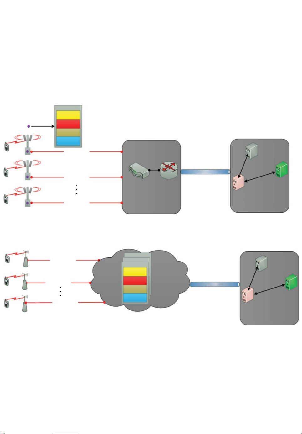
between the C‐RAN core network and the small cell. Figure1.1 shows definitions of
Page 15
BBU
(a)
(b)
X2 Sync
Layer 3
Layer 2
Layer 1
MME = Mobility management entity
SGW = Serving gateway
PGW = Packet data gateway
EPC = Evolved packed core
UE
UE
UE
UE
UE
UE
BS 1
BS 2
BS N
RRU 1
RRU 2
RRU N
RAN fronthaul
RAN fronthaul
RAN fronthaul
RAN backhaul
RAN backhaul
RAN backhaul
Aggregation switch Router
Aggregation point
BBU N
BBU 2
BBU 1
X2 Sync
Layer 3
Layer 2
Layer 1
BBU pool cloud
MME
Transpor t backhaul
PGW
SGW
Core network (EPC)
MME
Transpor t backhaul
PGW
SGW
Core network (EPC)
Figure1.1 Communication haul segments of (a) legacy and (b) emerging C‐RAN mobile network
Page 16

4 Backhauling/Fronthauling for Future Wireless Systems
the backhaul and fronthaul segments pertaining to legacy and emerging C‐RAN
architectures.
The future enhanced communication haul (be it backhaul or fronthaul) for 5G is
expected to be deployed around 2020 in order to support the exponential growth in
wireless data that is forecast over the next decade. Therefore, there is substantial
market interest in the development of ground‐breaking backhaul and fronthaul
solutions that can not only enhance today’s networks, but also provide a coherent
interference management approach in emerging technologies such as C‐RAN and
beyond. This communication haul challenge provided the inspiration for this book
and its title: Backhauling/Fronthauling for Future Wireless Systems.
The book intends to bring together all mobile stakeholders, from academia and
industry, to identify and promote technical challenges and recent results related to
smart backhaul/fronthaul research for future communication systems such as 5G. It
provides an overview of current approaches to backhauling legacy communication
systems and explains the rationale for deploying future smart and efficient backhauling/fronthauling infrastructure from architectural, technical and business points of
view using real‐life applications and use cases. The book is intended to inspire
researchers, operators and manufacturers to render ground‐breaking ideas in the
newly emerging discipline of smart backhauling/fronthauling over future, ultra‐dense
wireless systems. Moreover, detailed security challenges are presented to analyse the
performance of smart backhauling/fronthauling for future wireless. It is clear that
smart backhauling/fronthauling deployment can offer a palette of interesting colours
capable of painting new business opportunities for mobile stakeholders for next
generation wireless communication systems. This is the first book of its kind on smart
backhauling/fronthauling for future wireless systems which updates the research
community on the communication haul roadmap, reflecting current and emerging
features emanating from the 3GPP group.
To guide the reader through this adventure, the book has the following layout. In
Chapter 2, a reference architecture for the future radio communication haul is
presented from a 5G perspective. 5G networks are anticipated to obtain Shannon‐
level and beyond throughput and almost zero latency. However, there are several
challenges to solve if 5G is to outperform legacy mobile platforms; one of these is the
design of the communication ‘haul’. Traditionally, the backhaul segment connects the
radio access network (RAN) to the rest of the network where the baseband processing
takes place at the cell site. However, in this chapter, we will use the concept of
‘ fronthaul access,’ which is recently gaining significant interest since it has the potential to support remote baseband processing based on adopting a cloud radio access
network (C‐RAN) architecture that aims to mitigate (or coordinate) interference in
operator‐deployed infrastructures; this eases significantly the requirements in
interference‐aware transceivers. To do this, we provide a reference architecture
that also includes a network and protocol architecture and proposes a so‐called
‘cloud resource optimizer’. This integrated solution will be the enabler for
Page 17

Introduction: The Communication Haul Challenge 5
RAN‐as‐a‐Service, not only paving the way for effective radio resource management,
but opening up new business opportunities for virtual mobile service providers.
Emerging channel transmission approaches and the possibility of using higher
frequency bands, such as massive MIMO and millimetre‐wave (mmWave), respectively, are of paramount importance for future wireless systems and for the communication haul. Chapter3 introduces the fundamentals with regard to massive MIMO and
mmWave communication, and their suitability for small‐cell backhauling and
fronthauling. Furthermore, a performance analysis model for wireless backhauling
ofsmall cells with massive MIMO and mmWave communication is outlined. Using
this model, some numerical results on the performance of massive‐MIMO‐ and/or
mmWave‐based wireless backhaul networks are presented.
C‐RAN promises considerable benefits compared to decentralized network
architectures. Centralizing the baseband processing enables smaller radio access
points as well as cooperative signal processing and ease of upgrade and maintenance.
Further, by realizing the processing not on dedicated hardware, but on dynamic and
flexible general‐purpose processors, cloud‐based networks enable load balancing
between processing elements to enhance energy and cost efficiency. However,
centralization also places challenging requirements on the fronthaul network in terms
of latency and data rate. This is especially critical if a heterogeneous fronthaul is
considered, consisting not only of dedicated fibre but also of, for example, mmWave
links. A flexible centralization approach can relax these requirements by adaptively
assigning different parts of the processing chain either to the centralized baseband
processors or the base stations based on the load situation, user scenario and the availability of the fronthaul links. This not only reduces the requirements in terms of
latency and data rate, but also couples the data rate to the actual user traffic.
In Chapter 4, a comprehensive overview of different decentralization approaches
is given, and we analyse their specific requirements in terms of latency and data
rate. Furthermore, we demonstrate the performance of flexible centralization and
providedesign guidelines on how to set up the fronthaul network to avoid over‐ or
under‐dimensioning.
Heterogeneous backhaul deployment using different wired and wireless
technologies is a potential solution to meet the demand in small‐cell and ultra‐dense
networks. Therefore, it is of cardinal importance to evaluate and compare the
performance characteristics of various backhaul technologies in order to understand
their effect on the network aggregate performance and provide guidelines for system
design. In Chapter5, the authors propose relevant backhaul models and study the
delay performance of various backhaul technologies with different capabilities and
characteristics, including fibre, xDSL, mmWave and sub‐6 GHz. Using these models,
the authors aim to optimize the base station (BS) association so as to minimize the
mean network packet delay in a macro‐cell network overlaid with small cells.
Furthermore, the authors model and analyse the backhaul deployment cost and show
that there exists an optimal gateway density that minimizes the mean backhaul cost
Page 18

6 Backhauling/Fronthauling for Future Wireless Systems
per small‐cell base station. Numerical results are presented to show the delay
performance characteristics of different backhaul solutions. Comparisons between
the proposed and traditional BS association policies show the significant effects of
backhaul on network performance, which demonstrates the importance of joint
system design and optimization for both the radio access and backhaul networks.
The small‐cell network (also called a HetNet) has been recognized as a potential
solution to offer better service coverage and higher spectral efficiency. However, the
dense deployment of small cells could cause inter‐cell interference problems and
reduce the performance gains of HetNets. Various techniques have been developed
in 4G for tackling inter‐cell interference. In particular, the inter-cell interference
coordination (ICIC) technique can coordinate the data transmission and interference
in two neighbouring cells. In Chapter6, the authors consider a HetNet consisting of
macro‐cell networks overlaid with small‐cell networks that access the same spectrum
simultaneously. Here, the HetNet architecture assumes macro cells and small cells
interconnected via a high‐speed fronthaul/backhaul connection. In particular, due to
the mobility of wireless subscribers, the load and data traffic are different in every
active macro and small cell. The conventional static enhanced ICIC (eICIC) mechanism cannot ensure that adapting the almost blank subframes (ABS) duty cycle
corresponds to the dynamic network condition. Only the dynamic eICIC mechanism
is suitable for this non‐static network traffic. Therefore, the authors aim to develop a
dynamic interference coordination strategy for eICIC for maximizing system utilities
under given QoS constraints. In contrast to the traditional eICIC mechanism, the
proposed method does not add any backhaul requirements. Computer simulations
show that the performance in various scenarios of the dynamic eICIC mechanism
with QoS requirements is better than a static eICIC approach and the conventional
dynamic eICIC mechanism.
Cell selection for joint optimization considering backhauling technology is needed
for future wireless systems. In this regard, Chapter 7 provides a comprehensive
analysis for joint optimization considering the backhaul in terms of cell selection.
This chapter considers heterogeneous cellular networks, where clusters of small cells
are locally deployed to create hotspot regions inside the macro‐cell area. Most of
theresearch on this topic has focused on mitigating co‐channel interference; however,
the wireless backhaul has recently emerged as an urgent challenge to enable ubiquitous
broadband wireless services in small cells. In realistic scenarios, the backhaul may
limit the amount of signalling that can be exchanged amongst neighbouring cells,
which aims to coordinate their operations in real time; furthermore, in highly loaded
cells (such as hotspots), the backhaul can limit the data rate experienced by the end
users. Here, the authors develop a novel cell‐association framework, which aims to
balance the users amongst heterogeneous cells to improve the overall radio and
backhaul resource usage and increase the system performance. The authors describe
the relationship between cell load, resource management and backhaul capacity
constraints. Then, the cell‐selection problem is expressed as a combinatorial
Page 19

Introduction: The Communication Haul Challenge 7
optimization problem and two heuristic algorithms–called Evolve and Relax–are
presented to solve this dilemma. The analysis shows that Evolve converges to a near‐
optimal solution, leading to notable improvements with respect to the classic SINR‐
based association scheme in terms of throughput and resource utilization efficiency.
High‐speed and long‐range wireless backhaul is a cost‐effective alternative to a fibre
network. The ever‐increasing demand for high‐speed broadband services mandates
higher spectral efficiency and wider bandwidth to be adopted in the wireless backhauls. As wireless mobile networks evolve toward 5G, employing higher‐order modulation and performing multiband and multichannel aggregation for wireless backhauling
have become industry trends. However, commercially available wireless backhaul
systems do not meet the stringent requirements for both high speed and long range at
the same time. In Chapter8, the various system architectures for multiband and multichannel aggregation are discussed. The challenges for achieving high‐speed wireless
transmission in multiband and multichannel systems are addressed. These challenges
include: how to improve spectrum efficiency and power efficiency; how to prevent
inter‐channel interference; and how to ensure low latency in order to ensure resilient
packet delivery and load balancing.
Despite the significant benefits of C‐RAN technology in 5G mobile communication systems, C‐RAN technology has to face multiple inherent security challenges
associated with virtual systems and cloud computing technology, which may
hinder its successful establishment in the market. Thus, it is critical to address
these challenges in order for C‐RAN technology to reach its full potential and
foster the deployment of future 5G mobile communication systems. Therefore,
Chapter9 presents representative examples of possible threats and attacks against
the main components in the C‐RAN architecture in order to shed light on the
security challenges of C‐RAN technology and provide a roadmap to overcome the
security bottleneck.
In conclusion, we firmly believe this book will serve as a useful reference for early‐
stage researchers and academics embarking on this radio communication haul
odyssey, but beyond that, it targets all major 5G stakeholders who are working at the
forefront of this technology to provide inspiration towards rendering ground‐breaking
ideas in the design of new communication hauls for next‐generation systems.
References
[1] Ericsson (2013) Mobility report, June.
[2] Andrews, J. G., Buzzi, S., Choi, W., Hanly, S. V., Lozano, A., Soong, A. C. K. and Zhang, J. C.
(2014) What Will 5G Be? IEEE Journal on Selected Areas on Communication, 32(6), 1065–1082.
[3] Huawei Technologies Co. (2013) 5G: A technology vision. White paper.
[4] Osseiran, A., Boccardi, F., Braun, V., Kusume, K., Marsch, P., Maternia, M., Queseth, O., Schellmann,
M., Schotten, H., Taoka, H., Tullberg, H., Uusitalo, M. A., Timus, B. and Fallgren, M. (2014)
Scenarios for 5G mobile and wireless communications: The vision of the METIS project. IEEE
Communications Magazine, 52(5), 26–35.
Page 20

8 Backhauling/Fronthauling for Future Wireless Systems
[5] Parkvall, S., Dahlman, E., Furuskär, A., Jading, Y., Olsson, M., Wanstedt, S. and Zangi, K. (2008)
‘LTE Advanced–Evolving LTE towards IMT‐Advanced,’ Vehicular Technology Conference, 21–24
September, pp. 1–5.
[6] 3GPP (2011) ‘Feasibility Study for Further Advancements for E‐UTRA (LTE‐Advanced) (Release
10),’ TR 36.912, V10.0.0, March.
[7] China Mobile Research Institute (2011) ‘C‐RAN: The Road Towards Green RAN’. Technical report,
April. Available at: http://labs.chinamobile.com/cran/wp‐content/uploads/CRAN_white_paper_
v2_5_EN.pdf.
[8] Checko, A., Christiansen, H. L., Yan, Y., Scolari, L., Kardaras, G., Berger, M. S. and Dittmann, L.
(2015) Cloud RAN for Mobile Networks–A Technology Overview. IEEE Communications Surveys
Tutorials, 17(1), 405–426.
www.ebook3000.com
Page 21

2
A C‐RAN Approach for5G
Applications
Kazi Mohammed Saidul Huq, Shahid Mumtaz and Jonathan Rodriguez
Instituto de Telecomunicações, Aveiro, Portugal
2.1 Introduction
Nowadays mobile Internet is a pervasive phenomenon. In the last decade, this
phenomenon, along with the market drive for novel software applications spurred by
the availability of smartphone handsets, has led to an unprecedented increase in data
traffic. Researchers and experts predict that this upward trend will continue as the 5G
community envisions new usage scenarios that involve connecting people, machines
and applications through a mobile infrastructure. For this reason, the current technology requires a radical change to cater for this new tidal wave of mobile data, which
has led us to the fifth generation (5G) communications era [1]. 5G will be expected to
deliver a new era of wireless broadband connectivity, shaped by emerging use cases
that aim to interconnect devices (the Internet of Things– IoT), enhance quality of
experience (QoE) for the end user in terms of traditional mobile connectivity and be
the main platform for addressing critical emergency infrastructures. 5G will play a
role in the digitalization of Europe, and key targets include: increasing the peak data
rate by 100 times, enhancing network capacity by 1000 times, increasing energy
efficiency by 10 times and reducing latency by 30 times [2], all of which represent
significant and challenging design requirements in contrast to the legacy 4G system.
To achieve these targets, mobile stakeholders (such as operators, carriers and manufacturers) are contriving to incorporate macro cells and small cells into the design of
the radio access infrastructure. This has forced system designers to reconsider the
Backhauling/Fronthauling for Future Wireless Systems, First Edition.
Edited by Kazi Mohammed Saidul Huq and Jonathan Rodriguez.
© 2017 John Wiley & Sons, Ltd. Published 2017 by John Wiley & Sons, Ltd.
Page 22

10 Backhauling/Fronthauling for Future Wireless Systems
existing backhaul design of legacy 4G radio networks and to consider both a new
backhaul and fronthaul design for ultra‐dense heterogeneous networks (HetNets).
5G networks are increasingly perceived as carriers to support a fully fledged, data‐
centric application rather than voice‐centric applications. Hence, one of the principal
dilemmas operators are coming across nowadays is how to transform the existing
1
backhaul/fronthaul
infrastructure into an Internet Protocol (IP)‐based backhaul/fronthaul solution for hyper‐dense small‐cell deployment. With regard to the hauling of
data, the continued use of fibre will give rise to the same problems as experienced
today, which are mainly economic but also involve restrictions on deployment due to
the geographical locations of transceiver cell sites. Millimetre‐wave (mmWave) backhaul/fronthaul is an option, but technological and regulatory challenges are yet to be
addressed for its successful deployment. Another emerging solution is to exploit the
interworking and joint design of open access and backhaul/fronthaul network
architecture for hyper‐dense small cells based on cloud radio access networks
(C‐RANs) [3]. This requires smart backhauling/fronthauling solutions that optimize
their operations jointly with the access network optimization protocol. The availability, convergence and economics of smart backhauling/fronthauling systems
arethe most important factors in selecting the appropriate backhaul/fronthaul technologies for multiple radio access technologies (including small cells, relays and distributed antennas) and heterogeneous types of excessive traffic in the future cellular
network. However, in this chapter, we will use the concept of ‘fronthaul access’,
which is recently gaining significant interest since it has the potential to support
remote baseband processing based on adopting a C‐RAN architecture that aims
to mitigate (or coordinate) interference in operator‐deployed infrastructures; this
eases significantly the requirements in interference‐aware transceivers. Under the
umbrella of a C‐RAN scenario, we introduce the notion of a ‘cloud resource optimizer’, which requires reengineering the medium access control (MAC) to provide a
unified solution. The emergence of wireless fronthaul solutions widens the appeal for
small‐cell deployments, because a fibre‐only solution–the technology typically used
for fronthaul–is too expensive or just not available at many small‐cell sites. Moreover,
we will also present a few ideas of potential applications for C‐RAN‐based mobile
systems such as virtualization of device‐to‐device (D2D) services.
Following the introduction, this chapter is organized as follows. In Section2.2, we
provide a brief overview of different types of backhauling/fronthauling technologies,
and in particular, guide the interested reader through the transition from existing to
emerging communication haul technologies. In Section2.3, we present network and
protocol architecture for the baseline 3GPP coordinated multi‐point (CoMP) system,
as a starting point, and then evolve this towards the emerging C‐RAN‐based
architecture in Section2.4, which is widely seen as the next step on the mobile evolutionary landscape and indeed one step towards the 5G communication platform.
1
The terms backhaul and fronthaul are used interchangeably in this chapter.
Page 23
A C‐RAN Approach for5G Applications 11
Based on this platform, we develop an integrated solution for the cloud resource
optimizer, which defines a unified MAC. Section2.5 takes this design to the next
level by using device‐to‐device (D2D) communication as a use‐case application by
introducing a new small‐cell paradigm based on ‘on‐demand’ virtual small cells for
coping with the dynamic variations in mobile traffic throughout the day; which is also
an emerging scenario within the context of 5G. Finally, Section2.6 summarizes and
concludes this chapter.
2.2 From Wired toWireless Backhaul/Fronthaul Technologies
In this section we provide a brief summary of the different kinds of backhaul/fronthaul
technologies which are widely accepted and used by operators and service providers.
According to [4, 5] hauling technologies are divided into two major categories: wired
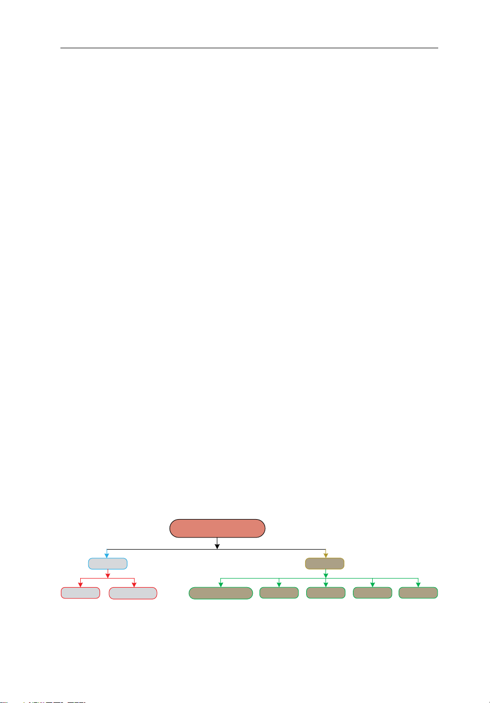
and wireless. Figure 2.1 shows the classification of backhaul technologies. For
example, in the case of the wired backhaul, copper cables are the conventional medium
whereas optical fibres are touted as an emerging hauling medium.
In wired backhaul, two types of physical media are widely used: copper cables and
optical fibres. Copper cables are the conventional hauling medium between base
transceiver stations (BTSs) and the base station controller (BSC) [4]. Currently,
copper cables are being replaced by optical fibres due to their higher rates and low
latency. Traditional copper‐based backhauling is used in digital subscriber line (DSL)
access networks [6]. The alternative to copper for mobile backhaul is fibre‐based
solutions that can provide almost unlimited capacity. The main fibre access options
include GPON (gigabit passive optical network), carrier Ethernet and point‐to‐point
(PTP) fibre [7].
There is another type of backhaul: wireless backhaul. This type of communication haul can be distinguished by the different frequency bands. Although the
channel traits are different in this type of backhaul owing to different bands, each
technology has its own merits and demerits. One very significant similarity amongst
these technologies over wired backhaul is fast and relatively cheap deployment. For
example, free space optics (FSO) use light to transmit data, but unlike relying on
fibre as a transmission medium, free space propagation is applied [8]. FSO links
Copper
Wired
Optical fibre
Backhaul/fronthaul
Wireless
Free space optics
Figure2.1 Different types of backhaul/fronthaul
SatelliteMicrowave mmWave Relaying
Page 24

12 Backhauling/Fronthauling for Future Wireless Systems
also create nearly zero interference between each other; the reason being the narrow
beam width. Microwave communication haul technologies utilize different bands of
carrier frequencies, ranging from 6 GHz to 42 GHz [5]. Microwave uses licensed
spectrum which, in turn, enhances deployment time and cost [9]. Recently, a new
paradigm is emerging under the wireless backhaul category: millimetre‐wave
(mmWave) technology [10]. The explosive developments in circuit technologies
have led to mmWave now being considered a viable option, and indeed foreseen as
shaping next‐ generation small‐cell wireless backhaul. There are three types of
frequency bands available for mmWave –60, 70/80 and 90 GHz [10]. These high
carrier frequencies can enable multi‐Gbps data rates [5]. As the 60 GHz band is
unlicensed and the higher bands only require an easy and inexpensive licensing
process, the links can be deployed much faster and at lower cost [11]. The relay
backhaul is another alternative, and is mainly used in the access link. Its inherent
advantage isthat relays use the same transmission technology and licences as the
access link.However, they also have similar shortcomings in terms of range (up to
a few kilometres), capacity (a few hundred Mbps) and interference [5]. Satellite
backhaul provides an answer for certain terrain where no other backhaul technologies are viable to deploy [4]. In general, T1/E1 is the physical transmission medium
over satellite links for cellular backhaul [12].
2.3 Architecture forCoordinated Systems According
toBaseline 3GPP
The C‐RAN incorporates both a joint signal processing capability and the resource
optimization of data belonging to different users which conventional coordinated
3GPP techniques cannot carry out due to high complexity and signal overhead during
coordination. Data and signalling are exchanged between different base stations
(BSs) through links which are usually capacity limited. This sometimes makes the
signalling exchange infeasible. In this section, we describe network and protocol
architecture of a coordinated system according to 3GPP.
Figure2.2 shows the network architecture of a coordinated 3GPP system. This
baseline scenario is based on BS cooperation, which recently attracted much interest
from the research community. In the 3GPP LTE‐Advanced, it is referred to as
coordinated multi‐point (CoMP) transmission and is being studied actively in LTE
release 11 [13].
The inter‐BS cooperation has been presented as an effective approach to mitigate
inter‐cell interference and hence improve cell edge throughput performance. Among
the several categories of CoMP technologies [14], we focus only on downlink joint
transmission (JT) CoMP in this chapter. In JT CoMP, downlink data can be simultaneously transmitted from multiple BSs to user equipment (UE). It is well known
that the cell‐edge performance is dramatically improved by JT CoMP. However,
Page 25
A C‐RAN Approach for5G Applications 13
UE
RRC IP
RLC MAC
Cell
1
BS
S1 S1
Layer 3
Layer 2
Layer 1PHY
Uu
X2-AP
SCTP
RRC IP
MAC
RLC
PHY
EPC
X2
GTP-U
UDP
RRC
IP
RLC MAC
PHY
Uu
Figure2.2 Network architecture of baseline 3GPP CoMP system
Cell
UE
1
1
BS
1
UE
X2
BS
Cell
2
2
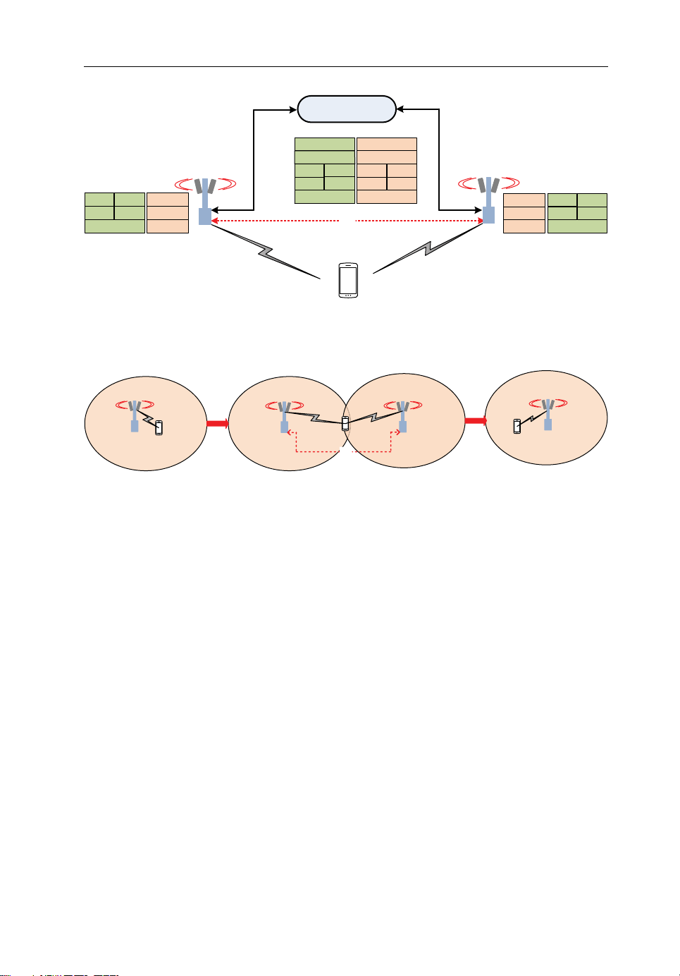
Figure2.3 Depiction of a JT CoMP use case
UE
BS
2
RRC
RLC MAC
Cell
Layer 3
Layer 2
Layer 1 PHY
IP
2
theperformance of JT CoMP can be degraded in the absence of a high‐speed and
low‐latency backhaul network [15].
This scenario is based on a distributed approach, where each BS has its own layers
of LTE protocol stack (i.e., physical (PHY), medium access control (MAC), radio link
control (RLC), packet data convergence protocol (PDCP)) and each BS scheduler
controls its own UE in the cell. The BSs are connected via an IP‐based X2 interface,
which acts as an asynchronous communication link for managing JT CoMP operation; this interface is also used for distributing downlink data between BSs. These BSs
are attached to the core network via the S1/S5 interface. Moreover, we assume that
two BSs are synchronized by a global positioning system (GPS).
To understand the underlying mechanics of CoMP, Figure 2.3 illustrates a JT
CoMP use case, where a user migrates between cells in an LTE network. Assume that
the UE is located at the cell centre in cell
receiving a downlink signal from BS
between cell
and cell2, the UE automatically triggers JT CoMP to improve the
1
performance at the cell edge by receiving a downlink signal from BS
. Finally, when the UE moves to cell2, the UE automatically terminates JT CoMP
BS
1
operation and BS
becomes the communication link.
2
, initially. The UE is attached to BS1 and
1
. However, as the UE moves to the cell edge
1
in addition to
2
Page 26
14 Backhauling/Fronthauling for Future Wireless Systems
UE
EPC
Data
Local sch
Resource
management
Co-ord sch
PDCP
RLC
MAC
PHY
Data
X2
resource
management
Co-ordinated
signalling
X2
Data forwarding
ControlMAC Synchronization
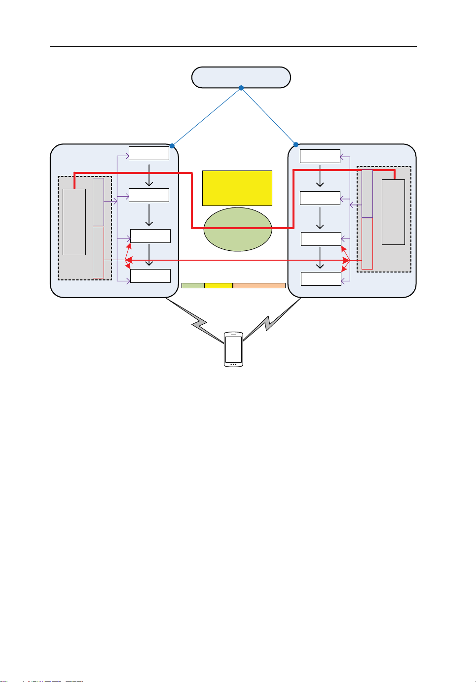
Figure2.4 Protocol architecture of baseline 3GPP CoMP system
PDCP
RLC
MAC
PHY
Local sch
Resource
Co-ord sch
management
Figure2.4 shows the protocol architecture to realize the simultaneous transmission
scheme based on the LTE standard. The UE reports two kinds of reference signal
received power (RSRP) messages to BS
the difference between RSRP
and RSRP2 (in dBm) is smaller than the predefined
1
: RSRP1 from BS1 and RSRP2 from BS2. If
1
CoMP threshold, then JT CoMP is started; if the difference exceeds the predefined
CoMP threshold, then JT CoMP is terminated.
When JT CoMP is triggered, the scheduler in BS
part in BS
to make sure that the radio resources are available for JT CoMP (see the
2
will first check with its counter-
1
heavy black line in Figure2.4). During JT CoMP, the downlink data are processed in
the following manner (see black arrows). First, PDCP, RLC and MAC are applied
tothe downlink data in BS
At the same time, the scheduler in BS
and the MAC protocol data unit (MAC‐PDU) is created.
1
provides the joint transmission time as well as
1
control information regarding MCS (modulation and coding scheme), radio resource
to be used and antenna mapping for the MAC‐PDU. The joint transmission time and
Page 27

A C‐RAN Approach for5G Applications 15
the control information are then attached to the MAC‐PDU and duplicated; one of
them is sent to PHY in BS
and other is sent to PHY in BS2 via the X2 interface. The
1
PHY processing is carried out at both BSs in parallel. Finally, the MAC‐PDU is
simultaneously transmitted from the two synchronized BSs at the specified joint
transmission time.
To transport a MAC‐PDU from BS
to BS2, the MAC‐PDU is encapsulated by the
1
GTP tunnelling protocol. The joint transmission time and the control information that
should be attached to this MAC‐PDU are included in a MAC‐control element (MAC‐
CE) in the MAC‐PDU.
2.4 Reference Architecture forC‐RAN
To overcome the limitations of CoMP, a holistic architectural change is expected via
connecting the BSs to central clouds. Unlike the baseline CoMP scenario described in
the previous section, in the C‐RAN most of the signalling takes place in the cloud and
is shared among sites in a pool of virtualized baseband processing units (BBUs). Due
to the fact that fewer BBUs are required in the C‐RAN compared to the traditional
architecture (legacy 3GPP scenario), C‐RAN also has the potential to reduce the cost of
network operation. This type of network architecture also improves scalability and
makes BBU maintenance easier. Different operators can share this cloud BBU pool,
which allows some to rent the RAN as a cloud service. Since BBUs from different sites
are co‐located in one pool, they can communicate with lower delays. This brings to the
forefront many other advantages, since existing mechanisms introduced in LTE‐A to
increase spectral efficiency, interference management and throughput, such as enhanced
inter‐cell interference coordination (eICIC) and CoMP, are greatly facilitated here.
2.4.1 System Architecture forFronthaul‐based C‐RAN
Emerging scenarios in cell deployment are heading towards the notion of cloud radio.
In this section we provide the reference system model for the C‐RAN scenario with
the description of its components. C‐RAN is a novel mobile technology that separates baseband processing units (BBUs) from radio front‐ends such as remote radio
units (RRUs). In this technology, BBUs of several BSs are positioned in a central
entity to form aBBUpool where the radio front‐ends of those BSs are deployed at
the cell sites [16–18]. Therefore, this new framework unfolds a new paradigm for
algorithms/ techniques that require centralized and cooperative processing. However,
the deployment of this new technology faces several potential research challenges,
which include latency, efficient fronthaul design and radio resource management for
a converged network.
Fronthaul enables a C‐RAN architecture in which all the BBUs are placed at a
distance from the cell site. The fronthaul transports the unprocessed RF signal from
Page 28

16 Backhauling/Fronthauling for Future Wireless Systems
the antennas to the remote BBUs. While the fronthaul requires higher bandwidth,
lower latency and more accurate synchronization than the backhaul, it does support
more efficient use of RAN resources; when coupled with legacy interference and
mobility management tools, this can significantly minimize interference in the structured part of the network, including multi‐tier cell interference.
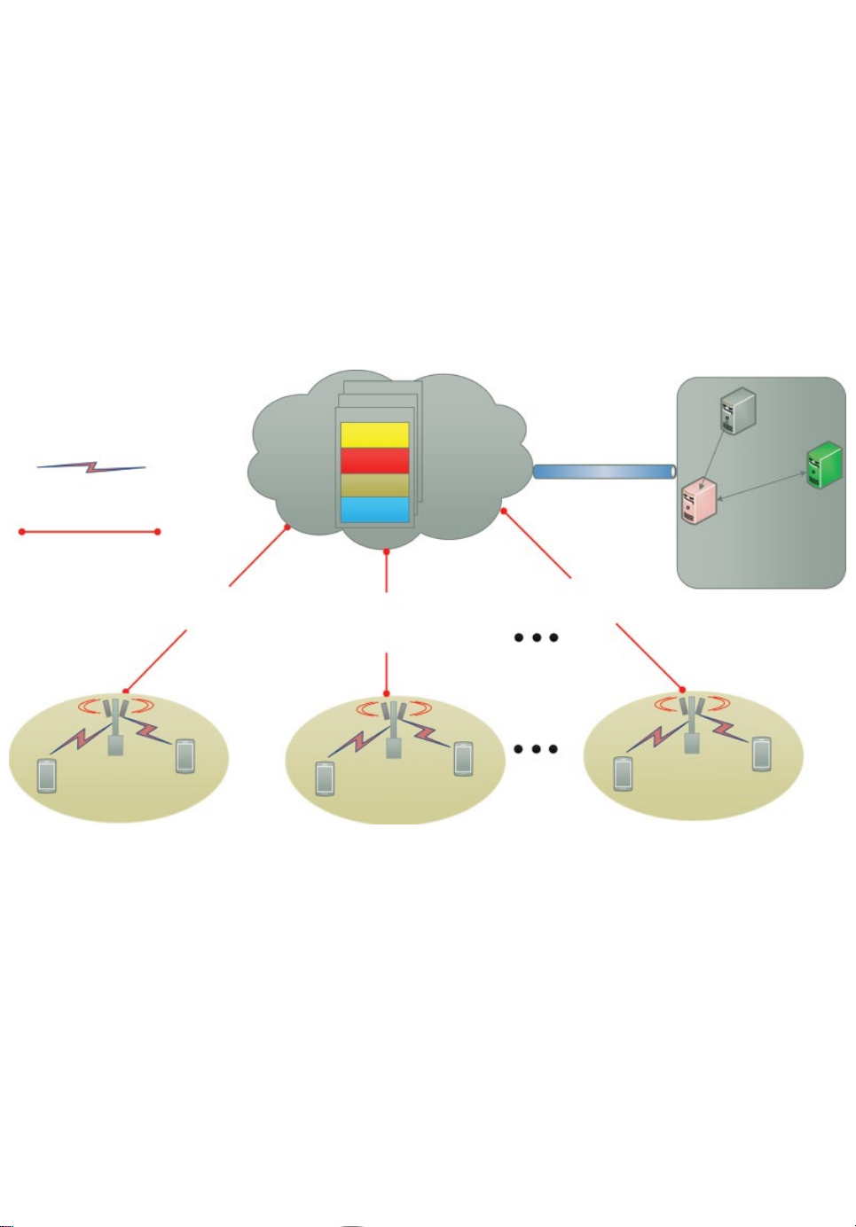
The general system model of the fronthaul‐based C‐RAN scenario is illustrated in
Figure 2.5, and consists of three main components [18], namely: (i) a centralized
BBU pool, (ii) remote radio units (RRUs) with antennas and (iii) a transport link, that
is a fronthaul network which connects the RRUs to the BBU pool. The RRU provides
the interface to the fibre as well as performing digital processing, digital‐to‐analogue
conversion, analogue‐to‐digital conversion, power amplification and filtering [16].
The distance between the RRU and the BBU can be extended up to 40 km, where the
ceiling range emanates from the processing and propagation delay. Optical fibre,
mmWave and microwave connections can be used. In the downlink, the RRUs transmit
the RF signals to the UEs, or in the uplink the RRUs carry the baseband signals from
the UEs to the BBU pool for further processing. The BBU pool is composed of BBUs
which operate as virtual base stations to process baseband signals and optimize
thenetwork resource allocation for one RRU or a set of RRUs. The fronthaul links
can constitute different technologies, namely wired (fiber → ideal) and wireless
(mmWave → non‐ideal). One can easily add or update any number of BBUs in
thiscloud depending on the needs and cell planning of the network operator. This C‐
RAN‐based architecture is also more energy efficient than the CoMP‐based scenario
due to reduced power consumption at the cell sites. In the C‐RAN network architecture,
no additional power is needed in cell sites other than for RRU operation.
By enabling joint processing in the cloud, key research challenges emerge related
to joint provisioning of resources between the different BBUs. This leads us to the
design of a so‐called ‘cloud resource optimizer’.
2.4.2 Cloud Resource Optimizer
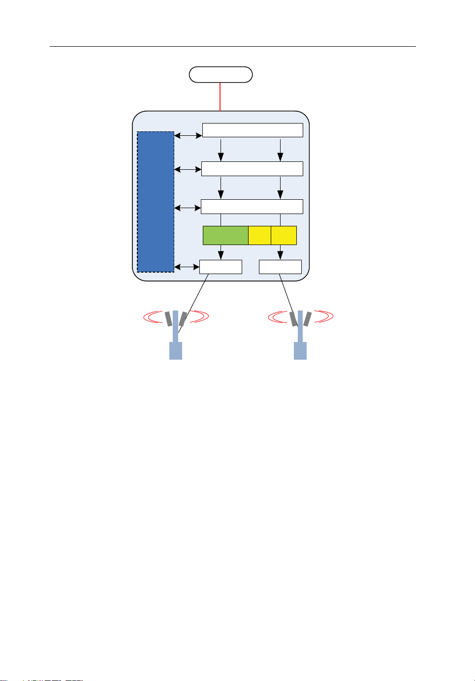
In this section we present the proposed cloud resource optimizer for the C‐RAN.
Interconnections and functions split between BBUs and RRUs are depicted in
Figure 2.6. Unlike a CoMP resource management module, where all the resource
management entities are separated for different BSs, this resource optimizer unifies
all the resource management operation including allocation, interference management
and signalling for different BBUs in the cloud pool. Inside this cloud resource optimizer, the PHYs from different RRUs are merged into one common MAC, control
(Ctrl) and Synchronization (Sync) entity. This operation prompts us to develop a new
MAC approach for this cloud‐based system. The MAC works as an enabler between
different types of radio access technologies (RAT) such as LTE (IMT technology) and
WiFi (non‐IMT technology).
Page 29
Microwave/mmWave
mmWave/optical fibre
Fronthaul
BBU N
BBU 2
BBU 1
X2 Sync
Layer 3
Layer 2
Layer 1
Fronthaul
BBU pool cloud
MME
Copper
PGW
SGW
Core network (EPC)
Fronthaul
RRU 1
RRU 2
RRU N
Figure2.5 Operator’s perspective on the fronthaul‐based C‐RAN scenario
Page 30
18 Backhauling/Fronthauling for Future Wireless Systems
2
1
EPC
Data
PDCP
RLC
Unified MAC
MAC Ctrl Sync
Cloud Resource Optimizer
PHY
I/Q I/Q
RRU
PHY
RRU
Figure2.6 Architecture of the cloud resource optimizer
We consider a novel, unified MAC frame for our C‐RAN scenario in Figure2.7,
unlike in legacy CoMP where each RAN has its own MAC. The shift in engineering
design to introduce the presence of a global MAC entity will not only improve the
efficiency (both spectrum and energy) of the system, but take a step towards reducing
the overall interference in the network. This unified MAC will be a modified version
of an existing LTE MAC frame described in [19].
As can be seen in Figure2.7, there are several MAC‐CEs in both the downlink and
uplink MAC. Following Table1 and Table2 from the 36.321 standard [19] (shown
here in Tables2.1 and 2.2), we can see the logical channel ID (LCID) types of MAC
header. The parts indicated by the bold rectangle emphasize the LCID values for the
various MAC‐CEs.
We define a new MAC‐CE for this purpose. We use the reserved element field for
specifying the unified frame, and this is indexed in the MAC‐PDU sub‐header by an
LCID value equal to 11001 in the uplink. The new element is called a unified frame
and is appended to the existing LCID values, such as the common control channel
(CCCH), cell radio network temporary identifier (C‐RNTI) and the padding.
Page 31

A C‐RAN Approach for5G Applications 19
MAC PDU/transport block
Header
Sub-header1Sub-header
2
RR ELCID = 11001 Unified frame
Table2.1 Values ofLCID forDL‐SCH (adapted from[19])
Index LCID values
00000 CCCH
00001–01010 Identity of the logical channel
01011–11011 Reserved
11100 UE Contention Resolution Identity
11101 Timing Advance Command
11110 DRX (Dynamic Reception) Command
11111 Padding
Ctrl
elements
Sub-header
K
Payload (SDU)Padding
Ctrl
Element 1
Ctrl
Element 2
Figure2.7 Unied MAC frame for C‐RAN
Ctrl
Element N
Table2.2 Values ofLCID forUL‐SCH (adapted from[19])
Index LCID values
00000 CCCH
00001–01010 Identity of the logical channel
01011–11001 Reserved
11010 Power Headroom Report
11011 C‐RNTI
11100 Truncated BSR (Buffer Status Report)
11101 Short BSR
11110 Long BSR
11111 Padding
Page 32

20 Backhauling/Fronthauling for Future Wireless Systems
This unified MAC in the cloud resource optimizer can provide differentiated
services to dual‐band devices which connect simultaneously to different
kindsof networks. Unlike the current convention where the UE selects either
licensed→LTE or unlicensed→WiFi, the cloud resource optimizer makes dynamic
decisions in the unified MAC framework, benefiting from the global knowledge available in terms of congestion level on the different radio networks
and the quality of service (QoS) requirements of the UE’s traffic. This novel
MACscheme has the potential to open up new opportunities in terms of traffic‐
orientated applications.
2.5 Potential Applications forC‐RAN‐based Mobile Systems
The evolution towards 5G is considered to be the convergence of Internet services
with existing mobile networking standards, leading to the commonly used term
‘ mobile Internet’ over small cell, with very high connectivity speeds. In addition,
green communications seem to play a pivotal role in this evolutionary path, with
key mobile stakeholders driving momentum towards a greener society through
cost‐effective design approaches. In fact, it is becoming increasingly clear from
emerging services and technological trends that energy and cost per bit reduction,
service ubiquity and high‐speed connectivity are becoming desirable traits for next‐
generation networks. Providing a step towards this vision, small cells are envisaged
as the vehicle for ubiquitous 5G services providing cost‐effective, high‐speed
communications.
These small cells are set up on demand and constitute a novel paradigm toward a
5G wireless system in two ways:
• A wireless network of cooperative small cells (CSC);
• Virtual small cells (VSC).
These novel, on‐demand small cells (CSC, VSC) have the ability to cope with
today’s wireless traffic dynamics and adjust their RF parameters accordingly.
Moreover, these on‐demand small cells can be used in various applications and scenarios en route to the accomplishment of the 5G goal. Among others, one of these is
D2D‐based C‐RAN, which will be discussed in the next section.
2.5.1 Virtualization ofD2D Services
D2D is widely considered an effective and efficient candidate approach for very
low latency communications in 5G [20], as well as being the enabler for improving
spectrum efficiency. In fact, by reusing the spectrum, two D2D users can form a
direct data link without exploiting explicitly the communication infrastructure
Page 33

A C‐RAN Approach for5G Applications 21
(BSand core networks). D2D communications will also be spurred on from the
application perspective, as D2D is considered an ideal deployment for proximity‐
based services, an example being social networking.
However, coexistence approaches are required in order for D2D users not to interfere with macro‐cell users, but at the same time to exploit spectrum appropriately
inanera where spectral resources are at a premium. In this context, we propose an
integrated solution where we combine technology paradigms such as C‐RAN and
virtual small cells in synergy to provide an enabler for effective D2D‐based communications [21]. This novel architecture has the potential to solve most of the challenges related to emerging 5G systems (capacity, latency, energy efficiency, CAPEX/
OPEX and mobility). Moreover, these D2D networks will be created on demand, for
example, if there are certain users at the cell edge with physically low battery levels,
then a user with a high battery level will become the cluster head and other users with
low battery levels will communicate in a D2D manner with the cluster head, while the
cluster head communicates directly with the C‐RAN.
In this architecture, we first split the control/data plane where the RRU provides
the signalling service for the whole coverage area and exploit these virtual small cells
for delivering data services for high‐rate transmission, complemented by a light control overhead and a selection option on the most appropriate air interface (mmWave
could be the best option), which is illustrated in Figure2.8.
2.5.2 Numerical Analysis
In order to analyse the performance of D2D‐based C‐RAN efficiently, we have
enhanced an existing system‐level simulator (SLS) with a centralized cloud entity to
control all the baseband processing, an RRU which acts as an antenna and a D2D user
pair. Moreover, we have also enhanced the following key performance indicators
(KPIs) to evaluate the performance of the proposed system.
• Throughput (with ideal fronthaul): The average throughput per cell is defined as
the sum of the total amount of bits being successfully received by all active users
in the system divided by the product of the number of cells being simulated in
thesystem and the total amount of time spent in the transmission of these packets
(the simulation time for LTE is TTI = 1 ms).
• Throughput (with non‐ideal fronthaul): The average throughput per cell is defined
as the sum of the total amount of bits being successfully received by all active users
in the system divided by the product of the number of cells being simulated in the
system, the total amount of time spent in the transmission of these packets (the simulation time for LTE is TTI = 1 ms) and the delay of the fronthaul link (10 ms).
Table2.3 shows the full list of simulation parameters.
Page 34

22 Backhauling/Fronthauling for Future Wireless Systems
Channel condition
BBU1
Control
Transport
Network
MAC
Physical
BBU2
Control
Transport
Network
MAC
Physical
Fronthaul
BBU N
Control
Transport
Network
MAC
Physical
Network
MAC
Physical
mmWave cell 30 GHz
LTE cell 800 MHz
RRU
D2D users
Cellular users
Figure2.8 On‐demand, device‐centric advanced C‐RAN
Routing:
finding the best
way of each flow
Assign resource
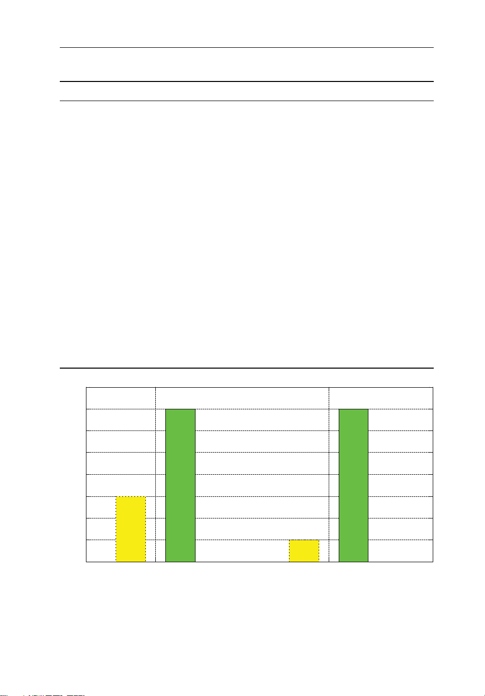
Figure2.9 shows the average throughput of the system with and without ideal
fronthaul. For this simulation, we consider 20 D2D pairs and 20 cellular users
(CUs). We also assume a fixed resource allocation between CUs and D2D users.
There are 100 resource blocks (RBs) in the LTE 20 MHz band, which are divided
equally among CUs and D2D users (50 RBs each). Each of these RBs is then
assigned to its corresponding users via a proportional fairness (PF) scheduler. CUs
on 50 RBs communicate using a cellular link (UE1↔RRU↔UE2), while D2D users
use a direct link (UE1↔UE2). When only CUs with ideal fronthaul are deployed,
the average throughput of the system is around 10 Mbit/s, but when this scenario is
enhanced with D2D, the average throughput rises to 20 Mbit/s. This increase in
throughput is due to the inclusion in the C‐RAN network of D2D, which, thanks to
its direct communication capability, enhances the average throughput of the system.
Moreover, if resource‐allocation schemes between CUs and D2D users with some
interference‐cancellation mechanism are considered, the average throughput of the
system increases even further.
Page 35
A C‐RAN Approach for5G Applications 23
Average throughput (Mb/s)
fronthaul)
fronthaul)
Table2.3 Simulation parameters
Name Parameter
System LTE‐A, 20 MHz, 2.6 GHz
Resource block (RB) 100
Duplexing method Cellular: FDD (downlink)
D2D: FDD (uplink using TDD timeslot)
Mode selection Shortest distance (cellular or D2D)
Resource allocation Fixed allocation
Channel estimation Perfect
Channel models Between D2D 40log10d[m] + 30 + 30log10(f [Mhz] + 49)
RRU→ D2D 36.7log10d[m] + 40.9 + 26log10(f [Mhz]/5) + α
RRU→ CU 36.7log10d[m] + 40.9 + 26log10(f [Mhz]/5) + α
shadowing
shadowing
Retransmission HARQ
Scheduler of eNB Proportional fairness (PF)
Power control Adaptive power
Traffic Full buffer
Fronthaul Ideal (no delay)/non‐ideal (10 ms delay)
Maximum transmit power RRU = 30 dBm,
Cellular Tx_Power = 24 dBm
D2D Tx_Power = 9 dBm
Noise figure 5 dBm for base station/9 dBm for D2D receiver
Thermal noise density −174 dBm/Hz
User speed Static
20
15
10
5
CU
(ideal fronthaul)
D2D
(Ideal fronthaul)
CU
(Non-Ideal
D2D
(Non-Ideal
Figure2.9 Throughput vs. ideal/non‐ideal fronthaul
Page 36

24 Backhauling/Fronthauling for Future Wireless Systems
When simulations with a non‐ideal fronthaul are run, a delay of 10 ms is experienced, as shown in Figure2.9, and the throughput of CUs drops to around 4 Mbit/s.
This is due to the fronthaul delay: the greater the delay, the lower the throughput.
But for the D2D case, throughput remains the same, because in D2D, data are transferred directly between devices and therefore there is a sort of ‘zero delay’ [22], but
this is still under the control of the C‐RAN, which is a benefit in terms of mobility
and handover.
Virtual small cells not only need to be ubiquitous and cost‐effective, but have to
deliver emerging services in a secure fashion in an era where applications will handle
‘extremely confidential data’ and money transactions. Therefore, 5G networks must
deliver a framework with a palette of security tools that are the enablers for a cross‐
system, end‐to‐end secure link which is fast and lightweight in nature. Virtual small
cells also open up the possibility for network operators to invest innetwork‐sharing
scenarios whereby operators can accommodate the foreseen increase in traffic whilst
reducing their investment in new infrastructure, and beyond that significantly reduce
their energy bill. These enhancements are currently addressed by 3GPP; however, this
raises new research challenges when applied to the virtual small environment.
Table2.4 shows the comparison of D2D‐based C‐RAN with existing LTE‐Advanced
(LTE‐A) technologies like CoMP, taking into consideration the main architectural
blocks of the communication network, like the evolved node B (eNB) (in LTE, the BS
is called the eNB).
2.6 Conclusion
To take a step towards the 5G vision, this chapter has described a C‐RAN reference
system architecture as the fundamental building block that has the potential to evolve
and to anticipate disruptive changes in users’ demands and small‐cell deployment. The
first part of this chapter introduces the C‐RAN architecture, which exploits RRU technology connected to the core network using backhaul technology based on fibre‐optic
links. C‐RAN was engineered so as to mitigate one of the key disabling features
affecting mobile communications since their inception: user interference. In C‐RAN,
the key is to harness all the baseband processing from all users within a common unit,
thus providing the operator complete control over the network and the ability to
coordinate signal transmissions, providing a significant step towards mitigating
interference in the network and alleviating interference‐aware transceivers. However,
the key aim of the chapter was to go beyond C‐RAN and examine the fronthaul component. In particular, we use the C‐RAN approach as a fundamental building block and
build on this to provide a more flexible platform that is able to support emerging use
cases under the 5G umbrella. In this context, we introduce the notion of a cloud resource
optimizer which works in synergy with a unified MAC, allocating virtual radio resources
on demand to support various applications, and potentially acting as the lynchpin to
Page 37

(continued )
bands
20 m 100 m/1000 m
1
Combination of
C‐RAN and D2D.
Improved capacity and
coverage at cell centre
and edge. More energy
efficient than CoMP
and C‐RAN. Relaying
Improved capacity and
coverage at cell centre
and edge. More energy
efficient than CoMP.
in cellular networks,
safety in public
services, sharing in
context‐based
applications.
Transferring of data
between users occurs
in licensed bands
directly. It is
managed by a cloud
central controller.
Transferring of data
between users occurs
directly, be it licensed
or unlicensed bands.
Within licensed bands,
a radio controlling
cloud is used for
transferring data.
3GPP release 11–12 IEEE 3GPP release 11–12 3GPP and IEEE
Table2.4 Comparison oftechnologies
Characteristic CoMP C‐RAN D2D [23] D2D:C‐RAN
Standardization
Frequency band Licenced bands Licenced bands Licenced bands Licenced/Unlicenced
Good (500–600 Mbps) Good (500–600 Mbps) Very good (1 Gbps) Excellent (2 Gbps)
2
Max transmission distance 500 m 100 m/1000 m
Latency >1 ms >1 ms ‘Zero latency’ ‘Zero latency’
Capacity
No No Yes Ye s
Uniformity of service
provision
Application Improved capacity at
cell edge. Longer
battery life of hand-
sets. Complete
operator control.
a central controlling
unit such as eNB is
used for transferring
data.
Infrastructure Within licensed bands,
Page 38

Combination of
C‐RAN and D2D.
CAPEX: No expenses
since users are using
their devices with all
types of technologies
such as WiFi, LTE and
D2D.
CAPEX: Subsidized
C‐RAN (BBU)
hardware. Installing
new RRUs.
OPEX:
Communication haul,
OPEX: Usage of
battery of the devices.
i.e., fronthaul. Leasing
and electric power
consumption of the cell
site. Operational cost
of RRUs.
Characteristic CoMP C‐RAN D2D [23] D2D:C‐RAN
Table2.4 (continued )
hardware.
Commissioning new
cell sites and towers.
Expenses CAPEX: Subsidized
OPEX:
Communication haul,
i.e., fronthaul. Leasing
and electric power
consumption of the
cell site. Operational
cost of eNBs.
These values are calculated under ideal channel and traffic conditions and with 2x2 MIMO using 20 Mhz of bandwidth.
100 m is for mmWave at 60 GHz and 1000 m is for fibre.
1
2
Page 39

A C‐RAN Approach for5G Applications 27
support the design of new 5G protocols/algorithms. In particular, we show how this
platform can not only support the emerging D2D paradigm, but is also able to support
the deployment of small‐cell technology which is seen as pivotal to the 5G story.
References
[1] Andrews, J. G., Buzzi, S., Choi, W., Hanly, S. V., Lozano, A., Soong, A. C. K. and Zhang, J. C.
(2014) What Will 5G Be? IEEE Journal on Selected Areas in Communications, 32(6), 1065–1082.
[2] Osseiran, A., Boccardi, F., Braun, V., Kusume, K., Marsch, P., Maternia, M., Queseth, O.,
Schellmann, M., Schotten, H., Taoka, H., Tullberg, H., Uusitalo, M. A., Timus, B. and Fallgren, M.
(2014) Scenarios for 5G mobile and wireless communications: the vision of the METIS project.
IEEE Communications Magazine, 52(5), 26–35.
[3] China Mobile Research Institute (2011) ‘C‐RAN: The Road Towards Green RAN.’ Technical
report, April. Available at: http://labs.chinamobile.com/cran/wp‐content/uploads/CRAN_white_
paper_v2_5_EN.pdf.
[4] Tipmongkolsilp, O., Zaghloul, S. and Jukan, A. (2011) The Evolution of Cellular Backhaul
Technologies: Current Issues and Future Trends. IEEE Communications Surveys Tutorials, 13(1),
97–113.
[5] Bartelt, J., Fettweis, G., Wubben, D., Boldi, M. and Melis, B. (2013) ‘Heterogeneous Backhaul
for Cloud‐Based Mobile Networks.’ Paper presented at the Vehicular Technology Conference
(VTC Fall), pp. 1–5.
[6] Eriksson, P. and Odenhammar, B. (2006) ‘VDSL2: Next important broadband technology,’
Ericsson Review No. 1.
[7] Orphanoudakis, T., Kosmatos, E., Angelopoulos, J. and Stavdas, A. (2013) Exploiting PONs for
mobile backhaul. IEEE Communications Magazine, 51(2), S27–S34.
[8] LightPointe Communications Inc. (2009) ‘Understanding the performance of free space optics.’
White paper.
[9] Giesken, K. (2002) Application of wireless technology in the mobile backhaul network. Bechtel
Telecommunications Technical Journal, 1(1), 62–70.
[10] Rappaport, T. S., Sun, S., Mayzus, R., Zhao, H., Azar, Y., Wang, K., Wong, G. N., Schulz, J. K.,
Samimi, M. and Gutierrez, F. (2013) Millimeter Wave Mobile Communications for 5G Cellular: It
Will Work! IEEE Access, 1, 335–349.
[11] Rangan, S., Rappaport, T. S. and Erkip, E. (2014) Millimeter‐Wave Cellular Wireless Networks:
Potentials and Challenges. Proceedings of the IEEE, 102(3), 366–385.
[12] Owens, J. (2002) Satellite Backhaul Viability. Bechtel Telecommunications Technical Journal,
1(1), 58–61.
[13] RP‐111117 Work Item Description, ‘Coordinated Multi‐Point Operation for LTE,’ Samsung, 3GPP
TSG RAN meeting #53, Fukuoka, Japan, September 13–16, 2011.
[14] Zhang, L., Nagai, Y., Okamawari, T. and Fujii, T. (2013)‘Field Experiment of Network Control
Architecture for CoMP JT in LTE‐Advanced over Asynchronous X2 Interface.’ Paper presented at
the Vehicular Technology Conference (VTC Spring), 2nd–5th June, pp. 1, 5.
[15] Okamawari, T., Zhang, L., Nagate, A., Hayashi, H. and Fujii, T. (2011) ‘Design of Control
Architecture for Downlink CoMP Joint Transmission with Inter‐BS Coordination in Next
Generation Cellular Systems.’ Paper presented at the Vehicular Technology Conference (VTC
Fall), 5th–8th September, pp. 1–5.
[16] Checko, A., Christiansen, H. L., Yan, Y., Scolari, L., Kardaras, G., Berger, M. S. and Dittmann, L.
(2015) Cloud RAN for Mobile Networks – A Technology Overview. IEEE Communications
Surveys Tutorials, 17(1), 405–426.
Page 40

28 Backhauling/Fronthauling for Future Wireless Systems
[17] Beyene, Y. D., Jantti, R. and Ruttik, K. (2014) Cloud‐RAN Architecture for Indoor DAS. IEEE
Access, 2, 1205–1212.
[18] Wang, R., Hu, H. and Yang, X. (2014) Potentials and Challenges of C‐RAN Supporting Multi‐
RATs Toward 5G Mobile Networks. IEEE Access, 2, 1187–1195.
[19] http://www.etsi.org/deliver/etsi_TS/136300_136399/136321/09.00.00_60/ts_136321v090000p.
pdf.
[20] Mumtaz, S., Huq, K. M. S. and Rodriguez, J. (2014) Direct mobile‐to‐mobile communication:
Paradigm for 5G. IEEE Wireless Communications, 21(5), 14–23.
[21] Huq, K. M. S., Mumtaz, S., Rodriguez, J., Marques, P., Okyere, B. and Frascolla, V. (2016)
Enhanced C‐RAN using D2D Network. IEEE Wireless Communications, submitted January, 2016
(under review).
[22] Huawei Technologies Co. (2013) ‘5G: A technology vision.’ White paper.
[23] Feng, D., Lu, L., Yuan‐Wu, Y., Li, G., Li, S. and Feng, G. (2014) Device‐to‐device communications
in cellular networks. IEEE Communications Magazine, 52(4), 49–55.
Page 41

3
Backhauling 5G Small Cells
withMassive‐MIMO‐Enabled
mmWave Communication
Ummy Habiba, Hina Tabassum and Ekram Hossain
Department of Electrical and Computer Engineering, University of Manitoba, Canada
3.1 Introduction
The exponential growth in the number of mobile subscribers and their corresponding
wireless data traffic has demanded the emergence of fifth generation (5G) cellular
networks. One of the key requirements for 5G is to increase the data rate radically, to
approximately 1000 times that of the current 4G technology. In this regard, network
densification is a straightforward way to increase the data rates. The idea of network
densification is to increase the density of small base stations (SBSs) in order to
enhance the number of users supported in a geographic region [1]. In principle, the
density of SBSs can be increased indefinitely until there is only one user supported
per SBS with its transmission and backhaul connections [1]. This extreme densification
raises a variety of challenges that include determining the appropriate cell associations,
managing inter‐tier and intra‐tier interference and providing high‐capacity backhaul
connectivity to SBSs at the same time.
Provisioning of cost‐effective and scalable backhaul solutions for 5G ultra‐dense
networks is challenging due to the need for ample resources for the backhaul
transmissions to/from a massive number of SBSs. Consequently, it is crucial to
consider both wired and wireless options for backhauling infrastructure of 5G cellular
networks depending on the location of the small cells and quality‐of‐service (QoS)
Backhauling/Fronthauling for Future Wireless Systems, First Edition.
Edited by Kazi Mohammed Saidul Huq and Jonathan Rodriguez.
© 2017 John Wiley & Sons, Ltd. Published 2017 by John Wiley & Sons, Ltd.
Page 42

30 Backhauling/Fronthauling for Future Wireless Systems
requirements of the users. Even though the existing wired backhaul ensures high
reliability, it may not be an economical and ascendable solution for densely deployed
SBSs. On the other hand, wireless backhauling solutions are cost‐efficient as well as
easily scalable to provide connectivity to small cells. Reasons include the possibility
of frequency reuse, easy operation and management and increased flexibility of
backhaul resource allocation.
There exist several wireless backhauling solutions for small cells, such as TVWS
800 MHz), sub‐6 GHz (licensed and unlicensed), microwave spectrum between
(
6 GHz and 60 GHz and FSO (free space optical) spectrum within the laser spectrum.
Moreover, the spectrum available between 30 and 300 GHz can offer 200 times greater
resources than the resources used for current cellular communications [2]. This
frequency band with the wavelengths ranging from 1 to 10 mm is referred to as
millimetre‐wave (mmWave) spectrum. Among various wireless backhauling options,
mmWave spectrum between 60 and 90 GHz is considered suitable for 5G networks
due to its small wavelength which allows the use of a large number of antenna
elements in a compact form, line‐of‐sight (LOS) propagation with larger channel
bandwidth and ample unlicensed spectrum.
Nonetheless, mmWave spectrum has a number of propagation challenges due to its
susceptibility to shadowing, rain attenuation and molecular absorption. The mmWave
signals cannot penetrate building walls and other blockages. Therefore, indoor and
outdoor users need to be served by separate BSs operating in mmWave frequencies
with large directivity gains. Consequently, highly directive antennas are essential for
mmWave BSs to generate narrow beams that suppress the impact of environmental
attenuation and interference arriving from neighbouring cells.
In this context, large‐scale antenna systems (often referred to as massive MIMO)
can be deployed at the transmitter and receiver to enhance the directivity. The massive
MIMO technology is well suited to the short‐wavelength mmWave signals, as a large
number of antenna elements can be installed within a small area of mmWave transceiver nodes, enabling highly directional beams with high capacity. Massive MIMO
technology coupled with efficient beamforming strategies diminishes the uncorrelated noise and short‐term fading effects irrespective of the number of users or BSs in
the network [3]. However, the performance of beamforming remains limited by the
channel estimation and acquisition techniques.
The rest of the chapter is organized as follows. In Section3.2, we first compare
different wireless backhauling solutions that currently exist. Section3.3 describes
the key features of mmWave propagation and massive MIMO technology. In
Section 3.4, we review the state-of-the-art in designing backhaul systems using
mmWave spectrum and discuss different LOS and NLOS topologies for mmWave
backhauling. In this section, we also outline the design and implementation issues
for massive‐MIMO‐enabled mmWave backhauling systems. Next, in Section3.5, we
model a massive‐MIMO‐enabled mmWave backhauling system and consider
maximizing the network rate through an efficient stable‐matching‐based user
Page 43

Backhauling with Massive-MIMO-Enabled mmWave Communication 31
association scheme. Numerical results are also presented in Section3.5 before the
chapter is concluded in Section3.6.
3.2 Existing Wireless Backhauling Solutions for5G Small Cells
The wireless backhaul connectivity of small cells is a function of the location and
density of the SBSs, line‐of‐sight (LOS) conditions between the wireless backhaul
hubs and SBSs, data rate requirements and additional costs for spectrum licensing.
Appropriate backhauling spectrum thus needs to be chosen as per the network requirements. To this end, in this section, based on the studies in [4–6], we detail the features
of different spectrum options for wireless backhauling.
• TVWS (600–800 MHz): The unused TV spectrum, known as TV white spaces
(TVWS), can be a suitable option for sparsely populated areas where communication
is limited to voice, video and real‐time gaming. This unlicensed spectrum can be
accessed opportunistically to backhaul small cells in a cognitive manner. TVWS
allows NLOS backhaul connectivity over a wider area (1–5 km) without any constraint
for antenna alignment. Due to opportunistic access, there is a risk of unavailability of
the spectrum. In addition, the backhaul connectivity must ensure that it does not
impose any interference on primary TV transmission. The data rates provided by
TVWS‐based backhauls may not be sufficient for backhauling 5G networks.
• Sub‐6 GHz: The licensed sub‐6 GHz spectrum (800 MHz– 6 GHz) is suitable for
backhauling SBSs in rural as well as urban areas. Without any additional hardware
or antenna alignment requirement, this spectrum allows NLOS communication
over a wider distance. In urban areas, it can provide backhaul coverage from 1.5 to
2.5 km whereas it can support backhaul links up to 10 km in rural areas. However,
the sub‐6 GHz spectrum is costly and provides narrow channel bandwidth which
limits the capacity. In dense areas, sub‐6 GHz spectrum is already in use; therefore,
it can suffer from severe interference. Sub‐6 GHz spectrum is thus not recommended
for backhauling 5G small cells in dense urban areas.
• Microwave (6–60 GHz): The microwave spectrum is a common choice for back-
hauling SBSs in urban and rural areas as it can provide 1 Gbps+ data rates for
real‐time and non‐real‐time services. However, the spectrum is costly and it requires
antenna alignment for LOS communication to achieve high directivity gain. The
size of the antennas designed for these frequency bands is relatively large, which
might not be feasible for SBSs. The microwave signals can provide backhaul
coverage up to 4 km. Therefore, microwave backhauls may be beneficial from the
perspective of data rate but may not be cost‐effective.
• Unlicensed millimetre wave (60–90 GHz): The unlicensed mmWave spectrum is
another promising candidate for backhauling 5G small cells in dense urban areas.
Since mmWave signals suffer from high propagation loss, a coverage distance
Page 44

32 Backhauling/Fronthauling for Future Wireless Systems
beyond 1 km may not be possible. However, this may work for densely deployed
small cells because of the reduced interference from adjacent links and, in turn,
increased capability of frequency reuse. These extremely high frequency signals
enable the installation of a large number of antenna elements within a small area
which enable high antenna array gain. The wider channel bandwidth offered by
mmWave spectrum and high directivity can provide multi‐Gbps data rates. Although
mmWave spectrum requires antenna alignment and LOS connectivity, there is no
additional spectrum cost.
• Free space optical (FSO) technology: FSO can be an alternative solution to traditional
radio frequency (RF) spectrum. The FSO link (laser beam) between laser photo‐
detector transceivers is not susceptible to electromagnetic interference. FSO links use
wavelengths in the range of micrometre and are capable of providing data rates in the
order of 10 Gbps over 1 km [7]. There is no licensing cost for FSO transmission.
However, there will be a hardware cost which is comparatively lower than optical
fibre links. For FSO links, LOS is required and laser beams are sensitive to weather
conditions such as rain, snow and fog. To minimize the effects of atmospheric attenuation, several techniques can be used that include aperture averaging, wave division
multiplexing (WDM), larger receive aperture, fine pointing mirrors (FPM), etc.
Among the existing wireless backhaul solutions, mmWave spectrum has the
potential to meet the requirements of 5G networks as it can provide wider channel
bandwidth with highly directive narrow beams and, in turn, low interference. The
small wavelength of mmWave also has the flexibility to incorporate the massive
MIMO technology and, in turn, support a large number of users with a high data rate.
As such, in dense urban areas, massive‐MIMO‐enabled mmWave links are highly
suitable for backhauling 5G small cells. In the following section we discuss the key
features of mmWave and massive MIMO technologies.
3.3 Fundamentals ofmmWave andMassive MIMO Technologies
3.3.1 MmWave Communication
As mentioned in the previous section, the capability of providing larger spectrum
with reduced interference and a high data rate makes mmWave spectrum attractive
forbackhauling ultra‐dense cellular networks. Nonetheless, the challenging features
of mmWave propagation include the following:
• Atmospheric attenuation: The extremely high frequencies in the mmWave spec-
trum are vulnerable to high propagation losses due to rain attenuation, oxygen or
othermolecular absorption. However, these environmental factors may not cause
significant propagation loss when considered for short‐range communications, for
example, ultra‐dense small‐cell networks. The results in [8] imply a minimal impact
Page 45

Backhauling with Massive-MIMO-Enabled mmWave Communication 33
of rain attenuation on mmWave frequencies. In times of heavy rainfall, the rain
attenuation for 28 GHz is only 1.4 dB over 200 m distance [9]. The attenuation due
to atmospheric absorption is also very low for mmWave frequencies, particularly
for 28 GHz and 73 GHz [9]. In the case of 60 GHz, oxygen absorption may cause
attenuation from 15 to 30 dB/km [10].
• Penetration losses: The mmWave frequencies experience high penetration loss on
the exterior surfaces of urban buildings whereas the penetration loss for indoor
materials is relatively low [9]. Thus, the outdoor BSs in the mmWave network can
hardly serve indoor users.
• Reflection factor: Large numbers of obstructions may affect the reflected multi-
paths of mmWave signals with large delays for both LOS and NLOS situations.
Even then, strong signals can be received within 200 m distance in a highly NLOS
environment [9]. Path‐loss exponents for the mmWave frequencies are within the
following range: 3.2–4.58 for NLOS and 1.68–2.3 for LOS environments [9, 11].
For a viable implementation of mmWave backhauling, the existing system designs
need to be improved. For instance, the high‐gain and electrically steerable antennas at
the user and BSs with appropriate beamforming can produce highly directive beams
and can combat large‐scale and small‐scale fading in the channel. The directivity gain
can be improved further by using spatial multiplexing. To achieve high antenna gain
in dense small‐cell networks, mmWave communication can combine polarization,
adaptive beamforming and new spatial‐processing techniques such as massive MIMO.
Recent advances in the design of integrated circuits and high‐directivity antennas
confirm the availability of appropriate hardware solutions for achieving high gain
with mmWave frequencies [12, 13].
3.3.2 MU‐MIMO withLarge Antenna Arrays
In dense small‐cell networks, MU‐MIMO technology can be used to provide backhaul connectivity to a large number of small cells simultaneously. Also, to ensure a
high data rate for mmWave backhaul links, MU‐MIMO with a large number of
antennas is highly beneficial. Ideally, there can be an infinite number of antennas that
can support an infinite number of users at the same time [3]. However, in practice, the
number of serving users is limited by the finite coherence time of the channel. The
increased number of antennas effectively mitigates the fast fading and uncorrelated
noise; however, the impact of interference cannot be ignored. The primary types of
interference in a massive MIMO system include the following:
• Pilot contamination: In a massive MIMO system, orthogonal pilot sequences are
typically used to train the massive MIMO BSs via uplink transmissions of the
users. Due to uplink–downlink reciprocity in a time‐division duplex (TDD)
Page 46

34 Backhauling/Fronthauling for Future Wireless Systems
massive MIMO system, the estimated channel information in the uplink is
exploited for the downlink transmissions. Note that the fundamental limitation of
the massive MIMO BSs arises from the reuse of pilot sequences in the neighbouring BSs, that is, transmissions of users in the neighbouring cells on the same
pilot sequence. This pilot reuse contaminates the channel estimates of a user in a
given cell. This phenomenon is referred to as coherent inter‐cell interference (or
pilot contamination). Nonetheless, even in the presence of pilot contamination,
massive MIMO BSs can serve a large number of users simultaneously, with
asymptotic SIR coverage probability given in closed form in [14].
Note that the impact of pilot contamination tends to be more severe in multi‐tier
networks; therefore, efficient pilot decontamination schemes will be of significant
importance. Some of the pioneering works on pilot decontamination include [15]
where multicast transmissions are used to eliminate the effects of pilot contamination.
• Traditional inter‐cell interference: Apart from pilot contamination, a user rate in a
massive MIMO system is also affected by the traditional inter‐cell interference
(i.e., non‐coherent interference).
• Intra‐cell or multi‐access interference: In MU‐MIMO, a BS serves multiple users
simultaneously using spatial multiplexing. Thus, users form clusters within a cell
where they share the same scattering environment with similar spatial channel
correlations. Due to imperfect channel estimation and, in turn, imperfect precoding
matrices, one communication stream can interfere with another stream within the
same cluster. Nonetheless, efficient precoding/beamforming schemes can eliminate
intra‐cell interference in MU‐MIMO systems.
With the increasing number of antennas in massive MIMO systems, the computational
complexity for designing the precoders also increases. In this regard, there are several
research works that aim to reduce the complexity of precoding design for massive
MIMO systems. A hierarchical interference mitigation technique proposed in [16]
utilizes an inner precoder for intra‐cell spatial multiplexing and an outer precoder for
inter‐cell interference cancellation. The iterative algorithms for precoding can reduce
the computational complexity significantly for massive MIMO systems. In [17], the
authors propose a low‐complexity precoding technique based on truncated polynomial expansion (TPE) that provides a better approximation of matrix inversion
and can be optimized to maximize the weighted max–min fairness for massive
MIMOsystems.
3.4 MmWave Backhauling: State oftheArt andResearch Issues
Moving toward dense small cells in the 5G network requires a combination of backhauling techniques that may vary according to the locations, target QoS requirements
and traffic load of the different SBSs. For example, indoor SBSs can obtain
Page 47

Backhauling with Massive-MIMO-Enabled mmWave Communication 35
high‐capacity backhauls from the existing wired infrastructure. By contrast, it can be
more complex and expensive to set up wired backhaul connectivity for outdoor SBSs
as they can possibly be installed below roof‐top level, on exterior walls of buildings,
street lamps or other street fixtures. In such scenarios, wireless backhauling solutions
can serve the purpose. In this section, we will discuss and review the state of the art
of LOS and non‐LOS mmWave backhauling in terms of feasibility, topology and
implementation and will then detail the fundamental challenges that exist in massive‐MIMO‐enabled mmWave backhaul systems.
3.4.1 LOS mmWave Backhauling
3.4.1.1 Point‐to‐Point (PtP) Topology
PtP topology is the traditional method of wireless backhauling in cellular networks.
The mmWave frequency ranging from 60–90 GHz can be used to form PtP beams
mitigating the deleterious effects of oxygen/molecular absorption and rain attenuation.
Due to the limitation of mmWave propagation, the inter‐site distance of picocells
needs to be within 100 m for reliable PtP X2‐based backhaul links [18]. The mmWave
frequencies allow the formation of two or more PtP links at the same location using
highly directive antenna arrays.
3.4.1.2 Point‐to‐Multipoint (PtMP) Topology
PtMP topology could be another suitable alternative to PtP backhauling. The PtMP
wireless links are based on a hub and remote concept [19]. For example, a small
cell with fibre‐based backhaul connection can serve as a wireless backhaul hub
and can support the backhaul transmission of six to eight small cells at a time. A
PtMP in‐band backhauling system was proposed in [20], where mmWave spectrum was used in both the backhaul and access links. A time‐division multiplexing
(TDM)‐based scheduling algorithm was proposed for PtMP mmWave backhauling, where SBSs are partitioned into three sectors. In this scheduling algorithm,
the backhaul links and access links are scheduled simultaneously in an adaptive
manner and the hub steers beams toward the neighbouring SBSs in one sector in
each time slot.
3.4.1.3 Mesh Topology
In the case of some physical obstructions, the small cells might need multiple links
for reliable backhauling; therefore, the flexibility of the backhauling system can be
improved further by using a multi‐hop mesh network. In the multi‐hop mesh topology,
long‐distance backhaul links are replaced by multiple short links, ensuring the
Page 48

36 Backhauling/Fronthauling for Future Wireless Systems
reliability of the backhauling system. However, the processing and accessing delays
at each hop may affect the performance of the backhauling links.
Recently, [5] considered a flexible mesh connectivity in mmWave backhauls with
a strict bound on latency. Electrically steerable antenna arrays are used in this
directed‐mesh connection operating at mmWave frequencies. Each node is capable of
self‐tuning its parameters to obtain an optimal path that provides maximal throughput
and minimal latency. To achieve this optimal performance, a TDM‐based joint scheduling and routing algorithm is implemented where the link parameters are updated in
real time. The joint scheduling of transmission over access and backhaul links using
mmWave frequency maximizes the spatial reuse while managing the intra‐cell and
inter‐cell interference efficiently [21]. In addition to the densely deployed SBSs, the
density of the wireless devices can also be very high in a 5G network. For such a
scenario, the centralized MAC scheduling algorithm proposed in [21] suggests
enabling direct device‐to‐device (D2D) transmission for optimal path selection and
concurrent transmission scheduling over the access link and backhaul links. In some
cases, their proposed algorithm can achieve near‐optimal performance in terms of
throughput and latency.
The self‐backhauling architecture proposed in [22] demonstrates an improved
multi‐hop mesh networking where a fraction of SBSs have wired backhaul and others
are backhauled wirelessly. Each wired SBS provides backhaul links to multiple SBSs
using mmWave frequency without imposing any interference. The authors characterized the mmWave network as noise‐limited where the interference power does not
cause any harm for a moderate density of SBSs. The authors analysed network
performance in terms of coverage rate for different combinations of the fraction of
wired backhauled SBSs and mmWave backhauled SBSs. The results presented in [22]
show that increasing the fraction of wired backhauled SBSs can improve the coverage
rate significantly. However, if the density of the wired backhauled SBSs is kept
constant, then the rate will eventually saturate for increasing density of the wireless
backhauled SBSs. In the same self‐backhauling mmWave network, the authors also
investigated the impact of the co‐existence of an ultra‐high‐frequency (UHF) network
with a mmWave network.
3.4.2 NLOS mmWave Backhauling
In practice, it is likely that LOS backhaul links will be blocked by buildings or other
surrounding objects. This renders the use of the mmWave frequency for backhauling
more difficult. Also, such links are susceptible to rain attenuation, oxygen absorption
and beam misalignment (due to wind, vibration and other environmental factors). As
such, it is important to have accurate directed beamforming capability with high gains
and subtle beam alignment for mmWave backhaul links. In the case of non‐LOS
wireless backhaul links, the diffracted ray gives the propagation loss for the desired
Page 49

Backhauling with Massive-MIMO-Enabled mmWave Communication 37
link and other reflected rays are treated as interfering links. To determine the gain for
the desired link, the antenna array for each link is steered toward the point of
diffraction. The mmWave frequency therefore enables a very narrow beam with high
antenna gain, which, in principle, diminishes the spatial interference. However, the
interference cannot be completely ignored in a scenario with ultra‐dense deployment
of small cells where the probability of spatial interference is high.
The NLOS PtP backhauling model considered in [23] includes the effect of rain,
oxygen absorption (for 60 GHz) and antenna misalignment. For their system model, the
simulation results show that the high‐frequency links (60 and 73 GHz) form high‐gain
narrower beams with a fading and implementation margin that can compensate for
additional propagation losses (due to rain and other factors) to some extent. In [18], the
authors proposed a high‐gain beam‐alignment technique using a hierarchical beamforming codebook which is computationally efficient. Their proposed framework adaptively
samples the subspace and forms an optimal beam that maximizes the received SNR. In
order to validate their framework they also investigated the wind effects on beam
alignment using pole movement analysis. Their analysis also shows how frequently
beam alignment needs to be performed. The large antenna arrays are sensitive to beam
misalignment. Therefore, more research work on mmWave backhaul links is required to
investigate the trade‐off between array size and achievable beamforming gain.
3.4.3 Research Challenges forBackhauling in5G Networks
As mentioned earlier, for ultra‐dense 5G networks, the mmWave frequency is envisioned as a key technology that can provide Gbps backhaul connectivity due to ample
spectrum resources available in this frequency band. Additionally, due to highly
directive beamforming gains, the integration of massive MIMO to the backhauling
infrastructure can further enhance the reliability of the mmWave wireless backhaul
links. Nonetheless, the successful roll‐out of the massive MIMO and mmWave technologies for wireless backhauling is hindered by several design and implementation
issues. To this end, in this section, we discuss some of the existing and anticipated
research issues in the design of massive‐MIMO‐enabled mmWave systems.
3.4.3.1 Provision ofSimultaneous Backhaul toMultiple SBSs
In ultra‐dense wireless‐backhauled small‐cell networks, system operators need to
support the backhauls of several SBSs at the same time. This requires a pool of spectrum resources that can be efficiently allocated to various small cells at the same time
such that the interference among backhaul streams remains below a prescribed limit.
In this context, the ample amount of spectrum in the mmWave bands and its noise‐
limited nature could potentially serve the purpose, especially when closely located
SBSs need to be backhauled. On the other hand, massive‐MIMO‐based backhauling
Page 50

38 Backhauling/Fronthauling for Future Wireless Systems
is another technique which could potentially support the backhauls of multiple SBSs
within the coverage of a massive‐MIMO‐enabled backhaul hub. This solution is more
suitable for backhaul transmissions between SBSs and the core network since it
exploits PtMP transmissions in the same time and frequency resource.
For multi‐user mmWave systems, multiple beams need to be formed at the same
time, which necessitates efficient precoding schemes. Also, developing multi‐user
hybrid analogue–digital precoding for mmWave is very challenging since it requires
more processing at the digital layer to manage inter‐cell/intra‐cell interference [24].
mmWave transceivers are thus expected to be expensive and complex in design.
Recently, a digitally controlled phase shifter network (DPSN)‐based hybrid precoding/combining scheme proposed in [25] was shown to be capable of reducing the cost
and complexity of mmWave transceivers.
3.4.3.2 Acquisition ofChannel State Information (CSI)
With multi‐user massive MIMO technology and efficient beamforming, it becomes
possible to serve the backhauls of a large number of SBSs with large degrees of
freedom. However, CSI estimation is an underlying requirement which strongly
impacts the performance of beamforming in massive MIMO systems. Traditionally,
in massive MIMO systems, the channels between transmitters and receivers are
estimated from orthogonal pilot sequences. These sequences are, however, limited in
number due to the finite coherence time of the channel. Therefore, it becomes crucial
to reuse the same pilot sequences in a multi‐tier network. This reuse of pilot sequences
in different cells leads to pilot contamination that limits the rate gains of a massive
MIMO system. To overcome this issue, coordinated multi‐point transmissions
(CoMP) can be employed. Also, a set of antenna elements in a massive MIMO system
can be leveraged to mitigate the impact of pilot contamination.
3.4.3.3 Adaptive Backhaul/Access Spectrum Selection
Traditionally, the network operators optimize the subchannels of a typical RF spectrum (sub‐6 GHz) that are allocated to a given user at its access links given the wired
backhaul at BSs. However, the possible use of a combination of frequency bands in
5G access/backhaul networks such as microwave, mmWave and sub‐6 GHz renders
this task particularly challenging. The reason is that the incurred interference and
offered network capacity at different frequency bands can be different for various
indoor/outdoor environments. For instance, compared to the traditional sub‐6 GHz
band, the mmWave frequencies have high penetration/attenuation losses that can
vary significantly for indoor and outdoor propagation environments. A careful
system‐level analysis is therefore required to adaptively select an appropriate
combination of frequencies for access/backhauls taking into account the crucial
www.ebook3000.com
Page 51

Backhauling with Massive-MIMO-Enabled mmWave Communication 39
factors such asinterference conditions at a given frequency, locations of the SBSs,
their surrounding environment, transmit/receive BS antenna characteristics and the
beamforming gains.
Moreover, the possibility of reusing the same frequency at both the backhaul and
access links (i.e., in‐band backhauling) with minimal interference is also crucial and can
vary for different spectrum bands. For example, the high directivity and noise‐limited
nature of mmWave spectrum can strongly support in‐band backhauling compared to
traditional sub‐6 GHz frequency spectrum. Consequently, choosing a feasible spectrum
band that can enhance data rates via in‐band backhauling is also crucial.
3.4.3.4 Backhaul Spectrum‐aware User Association
As mentioned previously, different frequency bands may result in significantly varying
data rates even in similar system settings. Therefore, optimal spectrum selection to
serve a user under given circumstances is crucial and requires the operation of SBSs in
a variety of frequency bands [26]. Nonetheless, deploying such SBSs may not be a
trivial task due to hardware modifications as well as deployment costs. Therefore,
from the perspective of network operators, the significance of determining an efficient,
low‐complexity, traffic‐offloading criterion is evident. Also, from the perspective of
users, it is important to choose a user‐association criterion that considers propagation
losses for the frequency used and antenna‐specific parameters of the SBSs.
3.4.3.5 Backhaul/Access Link Scheduling
In practice, the massive‐MIMO‐enabled backhaul system can serve a limited number
of backhaul streams at a given time and frequency resource. Consequently, the significance of backhaul scheduling becomes evident in dense cellular networks. In addition
to traditional time‐division‐based scheduling, more sophisticated scheduling
techniques can be implemented for mmWave massive MIMO networks. For example,
in [25], the proposed beam‐division‐multiplexing (BDM)‐based scheduling is shown
to improve performance gain for in‐band mmWave backhauling. Therefore, the
combination of TDM and BDM can make the user‐scheduling procedure much more
flexible. Moreover, unlike traditional user scheduling, the backhaul scheduling
requires consideration of the traffic load of a serving SBS and average achievable data
rate at the access links in addition to the backhaul channel conditions.
3.4.3.6 Number ofRF Chains
Typically, MIMO systems are equipped with few antennas and, in turn, the number of
employed RF chains, digital‐to‐analogue converters (DACs) and analogue‐to‐digital
converters (ADCs) can be comparable to the number of antennas. However, in a
Page 52

40 Backhauling/Fronthauling for Future Wireless Systems
massive MIMO system, deploying RF chains in a comparable quantity is not practically
feasible. Due to this limitation, the orthogonal channel estimation approach may not be
used even without pilot contamination. Also, the energy consumption of a MIMO transceiver increases as a function of the number of active RF chains due to the high energy
consumption of ADCs. Thus, the channel estimation and beamforming algorithms
should be designed taking into account the constraints on the number of RF chains.
3.4.3.7 Other Implementation Issues
The directed multi‐gigabit (DMG) PHY specification in the IEEE standard 802.11ad
suggests OFDM modulation for high‐data‐rate applications. As mmWave propagation
characteristics are quite different from those for the microwave, the OFDM parameters
for 3GPP LTE need to be modified. For mmWave communication, OFDM PHY
has different frame structures and can be implemented using QPSK, 16‐QAM and
64‐QAM. The bandwidth of OFDM subcarriers and guard intervals needs to be larger.
The basic TDD‐based mmWave frame has 10 subframes and each subframe contains
14 OFDM symbols [27]. When mmWave is used for wireless backhauling, subframes
can be configured to support multi‐hop transmission utilizing spatial multiplexing
[27]. The configuration of mmWave subframing needs further investigation.
3.5 Case Study: Massive‐MIMO‐based mmWave
BackhaulingSystem
As depicted in Figure3.1, we consider wireless backhaul hubs installed within macro
base stations (MBSs) to provide backhaul connectivity to SBSs or access points (APs)
over mmWave links utilizing massive MIMO technology. The APs use different
mmWave frequencies in the access and backhaul links. We assume that the APs and
user equipment (UEs) are equipped with directional antennas with sectorized gain
pattern. Each hub supports N
time block, each AP also schedules N
and Pa, respectively. During the training phase, each AP sends a preassigned
are P
h
orthogonal pilot sequence to the hub, which is estimated perfectly by the hub and the
pilot sequence is not used by any other neighbouring hub (i.e., no pilot contamination
is assumed). The channel estimation is facilitated with time‐division duplexing at the
hubs so that the channel reciprocity is guaranteed.
Since the walls of buildings are impenetrable to mmWave signals, indoor APs can
neither serve outdoor users nor interfere with outdoor AP transmission. In the outdoor
environment, the APs are deployed on the exterior of buildings or street fixtures where
users are more likely to be NLOS to the hubs and users. We focus on outdoor user
performance and assume that the hub–AP and AP–user channels fade independently
across time slots.
APs simultaneously with Mh antennas. Within the same
b
UEs. The transmission power of a hub and AP
a
Page 53

Backhauling with Massive-MIMO-Enabled mmWave Communication 41
H
{}H
i
{}
()
A
i
U
{}
()
U
k
j
j
i()
k
j()
UE
Core network
AP
MBS/
wireless
backhaul
hub
Massive MIMO
based mmWave
backhaul link
AP
UE
UE
UE
AP
AP
UE
Macro cell
Small cell
Blockage
NLOS link
MBS/
wireless
backhaul
hub
AP
UE
UE
AP
Figure3.1 Small‐cell network architecture incorporating massive‐MIMO‐based mmWave
backhauling system
3.5.1 System Model
We consider that backhaul hubs and APs are distributed according to homogeneous
Poisson point processes (PPPs) in a cellular region ℝ
and APs are
with density λH and
A
The locations of UEs are approximated by a PPP
denote by
A
the jth AP backhauled by the ith hub and
jth AP. The buildings and other outdoor blockages are modelled using the Boolean
scheme of rectangles [28]. In this model, the blockages are considered as a process of
random rectangles where the centres of the rectangles form a PPP Φ
The length, width and orientation of the rectangles are determined as independent and
identically distributed (i.i.d.) random variables. We also assume that the distribution
of blockages is stationary and does not vary with any translation or rotation. Over the
geographic area, the probability that a network node will be in the LOS region is
determined based on the size and density of the blockages [29]. Considering downlink transmission, we denote the distance between a transmitting node {X
2
. The PPPs formed by the hubs
with density λA, respectively.
j
with density λU. We
as the kth UE served by the
with density λb.
b
} and
t
Page 54
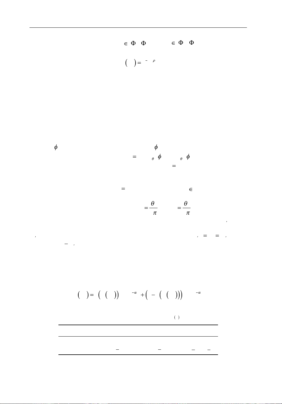
42 Backhauling/Fronthauling for Future Wireless Systems
X
tHA
,{}
rAU
{,}
l
/
t
l
r
l
DD D
l
l
l
tr
tttrrr
()
() ()
DG
l
tr tr,
()
Da
l
n
tr,
()
b nn({ })1 234,,,
c
2
c
2
k
j()
A
j
i()
A
j
i
()
k
j()
k
j()
A
j
i
()
DagG
jk
jk
,
2
jk
L
ll
LN
D
tr,
tr
c c
tr
()1
tr
receiving node {Yr} as Rl, where
and
. The LOS proba-
bility for the link is given by:
R
pR e
l
(3.1)
where ρ is the average LOS distance.
3.5.1.1 Directivity Gain
We model directional beamforming gains as marks of the PPPs and approximate the
actual beamforming pattern using the sectored gain pattern presented in [22, 28, 30] for
ad hoc and mmWave networks. The antenna pattern is represented as D
(ϕ), where G
G,g,θ
is the main lobe directivity gain, g is the side‐lobe directivity gain and θ is the beam width
of the main lobe with the antenna boresight direction ϕ at the node. For a given angle of
departure
gain for the link R
) between the target nodes, the directivity gain is
(l
0
at the transmitter and angle of arrival
is determined as
l
tr
,
at thereceiver, the total directivity
Gg
,, ,,
Gg
0
. For the desired link
G
. The number of beams
from interfering nodes is considered to be a discrete random variable.
Considering the probability distribution for four possible scenarios, the directivity
I
gain of the interfering links is
and bn constants as proposed in [29]. The probability distribution for the inter-
use a
n
fering links is shown in Table 3.1. Here,
with probability
t
and
t
r
. For example,
r
, where we
is
associated with
in the downlink represents that the main lobe of
and the random distribution of interference link from
is overlapped by a side lobe of
. The directivity gain of the interfering link will then be
probability
.
l
()
I
to
with
3.5.1.2 Path‐loss Model
MmWave links may experience either LOS or NLOS propagation. Therefore, the
path loss experienced by the link R
RpRKRpRKR
Table3.1 Probability distribution function of
i 1 2 3 4
a
i
b
i
ll
GtG
r
ctc
r
can be determined as:
l
L
1 (3.2)
gtG
r
Gtg
N
l
l
I
r
gtg
r
Page 55

Backhauling with Massive-MIMO-Enabled mmWave Communication 43
(( ))pR
l
UA
k
1
U
AH
j
A
N M
bh
�
A
i()
I
j
A
where
is the Bernoulli RV for the LOS probability p(Rl) and αL and αN are
the LOS and NLOS path‐loss exponents. The log‐normal shadowing and path loss
at a reference distance are approximated as K
respectively. We assume small‐scale fading h
and KN for LOS and NLOS,
L
as a normalized gamma random
l
variable.
3.5.1.3 User Association
We consider that each UE can associate with one AP which is backhauled by at most
one hub. The association between AP and UE is indicated by:
10,
kj
,.
j
if associated with
k
otherwise
Resources at the APs are uniformly allocated to a maximum of Q
i
j
UEs according to
a
the effective load. The percentage of resource consumption for a UE is denoted as
kj
j
U
. The hub–AP association indicator is considered as:
kj
10,
ji
,.
i
if associated with
j
otherwise
i
i1()
A
APs. The
h
Resources at the hubs are uniformly allocated among a maximum of Q
percentage of resource consumption for an AP is denoted as
ji
3.5.1.4 Interference Model
As we focus on a massive MIMO network with a large number of antennas implemented in hubs, where
, the large‐scale antenna arrays diminish the effects
of uncorrelated noise and the system is considered to be interference limited [3]. We
assume that efficient beamforming and a pilot decontamination scheme eliminate the
effects of intra‐cell interference and pilot contamination. Thus, an AP will receive
interference only from other hubs that are transmitting in the downlink. The interference received by
(the jth AP which is backhauled by the ith hub) is expressed as
j
follows:
l
bh
lH H
02:\
Ii i
H
Ph DLR
lij
I
I
l
,
I
i
A
. (3.3)
ji
ji
.
ji
Page 56
44 Backhauling/Fronthauling for Future Wireless Systems
k
j()
j
i()
I
.
A
j
i()
R.
k
j()
N
2
N
2
ab
m
,
The access link interference between the user element
and access point
be expressed as follows:
aa
i
lA A
02:\
I
j
Ph DLR
i
A
j
I
ljkll
,
I
I
U
kj kj
j
U
k
3.5.1.5 SINR andRate Calculation
In the massive MIMO regime, the SINR at the backhaul link for AP
imated as follows [31]:
2
l
lij
0
1
l
I
a
0
l,
0
I
b
0
(3.5b)
The SINR received at
where
is the thermal noise power. The user rate in the downlink is therefore cal-
2
1
MN
IN
b
hb
N
b
in the access link is given by:
Ph DLR
a
ljk
INR
a
0
Ph DLR
h
l
0
,
2
culated as:
can
A
(3.4)
can be approx-
(3.5a)
RBkjlog min
1SINR,SINR
(3.6)
where B is the bandwidth of the channel assigned to the user.
3.5.2 Maximizing User Rate
In the downlink transmission, the hubs forward the traffic to the APs over the backhaul links and then the APs forward the traffic to the desired users. The hubs can
support a fixed number of APs simultaneously and APs also have the constraint to
support a limited number of users at a time. Therefore, the downlink rate is greatly
affected by the association at the backhaul and access links. In this context, we formulate a user‐association problem for the downlink transmission to maximize the
overall user rate as follows:
ax
,
ji kj
i
AU
AU
j
kj kj kj
j
k
(3.7a)
R
Page 57

Backhauling with Massive-MIMO-Enabled mmWave Communication 45
A
AU
j
AU
A
ij
j
k
HA
AU
HA
.
H
12,,...,
A
12,,...,
Aa
A
H
HA
HA
b
aa() ,1
A
b
aa()
a
A
b
() ,
hH
h ab()
b
ha()
.. ,, ,
H
i
i
11 (3.7b)
ji
H
QQ
,,, (3.7c)
ji
ha
U
i
A
j
kj j
kj
i
j
k
i
,
Since solving this optimization problem can be computationally complex in real time,
we focus on devising less complex distributed user‐association solutions. The theory of
matching can be used to design efficient distributed solutions for user associations [32,33].
3.5.3 Matching Theory forUser Association
We address the combinatorial problem of user association in the downlink by transforming it to a two‐sided matching game. For two disjoint sets of players in the
matching game, a matching is performed between the two sets of players according
to each player’s preference metric. To obtain a stable matching, each player is assigned
a fixed quota which is referred to as the maximum number of players that each player
can be matched to. To solve the user‐association problem in our system model, the
association in the backhaul and access links is performed using the matching
framework presented in [33–35].
3.5.3.1 Matching Game forHub–AP Association
At first we consider a many‐to‐one matching game for the association between the
hubs and APs. We denote the set of hubs by
H and the set of APs by
A . Each AP can be matched with at most one hub and each hub can
have matching with one or more APs depending on its quota Q
. The preference
h
relations for hubs and APs depend on the channel state of each backhaul link. Each
AP aims to maximize its utility function given by its achievable rate. Considering a
random association, each AP calculates the rate that it can receive from each hub and
makes its preference list
its preference list
H
b
using the rates calculated from the initial random
h
h
over the hubs. Similarly, each hub constructs
a
association. Each hub gives a ranking score to each AP based on its preference list.
After constructing the preference lists, matching among the disjoint sets of hubs
and APs is performed iteratively until a stable match is found. A matching μ
that
b
represents the hub–AP association can be expressed as a function from the set
•
hQ h
•
•
into the set
and
if and only if
such that [33, 35]:
if
.
Page 58

46 Backhauling/Fronthauling for Future Wireless Systems
*
b
H
b
h
H
H
b
b
*
b
*
b
A
{, ,..., }12 A
U
{, ,..., }12 U
*
b
U
{}
Here, the matching function μb(a) denotes the matched APs and μb(h) represents
the matched hubs. As described in Algorithm 1 below, the APs first apply to their
most preferred hubs according to the preference list. If the quota of the hub Q
is not
h
overloaded, it will schedule the AP. If the quota is exceeded, the hub checks the ranking for the applicant AP. If the ranking of the AP is better than the rank of other
scheduled APs, then it discards the worst AP with maximum rank and associates with
the applicant AP. This will continue until all APs are associated and their preference
lists become empty. Thus, the algorithm will end with a stable matching
.
Algorithm 1: Matching algorithm forhub–AP association
1. input: ΦH, ΦA and Q
2. initialization: calculate the preference lists
h
and
,
A
respectively
3. each hub
4. while (at least one AP is free AND its preference list
gives a ranking score to APs based on
A
is not empty) do
5. each unassociated AP applies to its most preferred hub
in
A
6. if the Qh is not overloaded then
7. associate with the applicant AP
8. else
9. compare the ranking of the applicant with the
currently associated APs
10. if
then
11. discard the worst AP from the hub's current associations
12. associate with the applicant AP
13. discard the hub from the preference list of the
discarded AP
14. set the discarded AP as free
15. end if
16. end if
17. end while
18. output:
3.5.3.2 Matching Game forAP–UE Association
Once we have the stable matching
for the backhaul connectivity, we perform
another many‐to‐one matching game to find association among APs and UEs at the
access end. We consider the set of APs as
and the set of UEs as
. This matching game aims to match each UE with one AP and each
hub with one or more UEs depending on its quota Q
. Using the stable matching
a
at the backhaul end and a random association at the access end, each UE calculates
the rate that it can receive from each AP using Equation (3.6) and makes its
preference list
U
over the APs. APs also construct their preference list
uu
Page 59

Backhauling with Massive-MIMO-Enabled mmWave Communication 47
A
A
{}
aa
*
a
AU
AU
a
uu() ,1
U
a
uu()
U
b
() ,
aA
au
b
()
b
au()
*
b
*
a
A
U
A
A
U
U
*
a
depending on the total rate they can provide to the associated users.
Each AP also gives a ranking score to UEs based on its preference. To find a stable
matching
described in Algorithm 2. In this case, a matching μ
association is expressed as a function from the set
for the AP–UE association, matching is performed iteratively as
representing the AP–UE
a
into the set
such that:
•
aQ a
•
•
if and only if
and
Here, the matching function μ
if
.
(u) denotes the matched UEs and μb(a) represents
b
the matched APs. The two‐sided matching algorithms to find the hub–AP and AP–
UE association are guaranteed to converge as the applicant (AP or UE) never
applies to its preferred node (hub or AP) twice and thus the algorithm will have a
finite number of iterations [32]. The algorithms return the stable matching
and
whenever any unassociated AP or UE has no hub or UE left in its preference list,
respectively.
Algorithm 2: Matching algorithm forAP–UE association
1. input: ΦA, ΦU and Q
2. initialization: calculate the preference lists
respectively
3. each AP
gives a ranking score to UEs based on
4. while (at least one UE is free AND its preference list
is not empty) do
5. each free UE Uk applies to its most preferred AP in
6. if the Qa is not overloaded then
7. associate with the applicant UE
8. else
9. compare the ranking of the applicant with the
currently associated UEs
10. if
11. discard the worst UE from the AP's current
associations
12. associate with the applicant UE
13. discard the AP from the preference list of the
discarded UE
14. set the discarded UE as free
15. end if
16. end if
17. end while
18. output:
a
and
,
then
Page 60
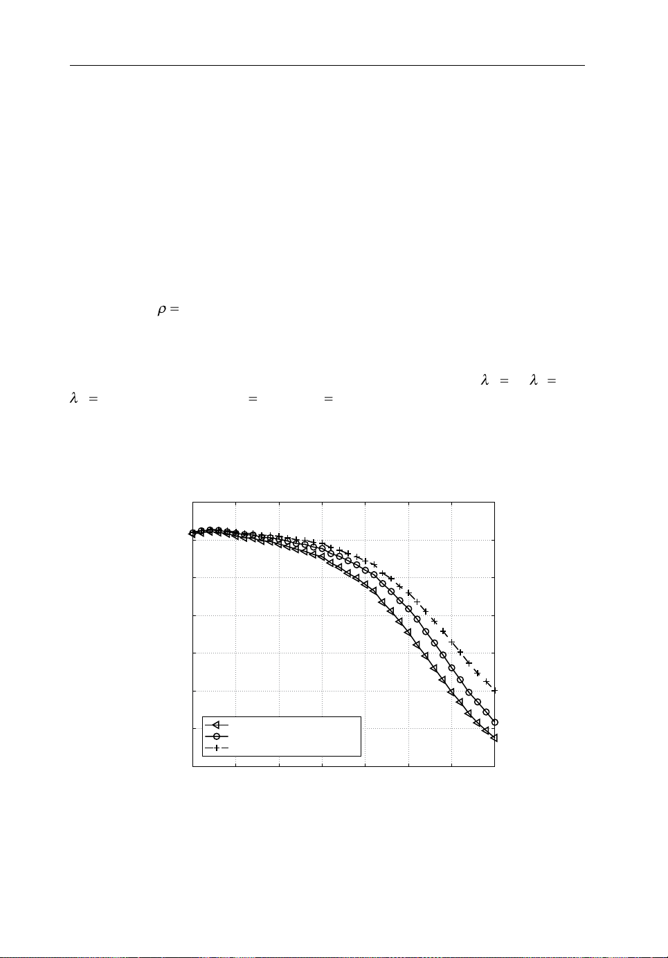
48 Backhauling/Fronthauling for Future Wireless Systems
141 4.
H
5
A
100
U
300
h
10
a
4
60
0.8
SINR threshold in dB
SINR coverage probability
3.5.4 Numerical Results
In this section, we present numerical results for the performance of a typical user in
the downlink with traditional distance‐based association and distributed stable
matching algorithms. The massive‐MIMO‐based mmWave backhaul hub is assumed
to be equipped with 256 antennas and operates at 60 GHz with channel bandwidth
of 2 GHz. The AP operates at 73 GHz and the channel bandwidth is 2 GHz. The
transmission power for the hub and AP are 46 dBm and 30 dBm, respectively. To
approximate the directivity gains for the hubs, AP and UE, we consider a 10 degree
beam width for the hub and AP with a main‐lobe gain of 18 dB and a side‐lobe gain
of −4 dB for both the mmWave hubs and APs. The directive beamforming for users is
approximated by 10 dB beams with 90 degree beam width. We assume the average
LOS distance
access and backhaul) are taken as 2 and 3.5, respectively.
First, in Figure3.2, we compare the SINR coverage probability for a massive‐
MIMO‐based mmWave backhaul system for the backhaul link and access link with
both microwave and mmWave frequencies. Here, we consider
per sq. km with
ilar blockage for microwave transmission. As shown in Figure 3.2, mmWave
frequencies offer a better SINR coverage than microwave transmission in the
access links.
m. The path‐loss exponents for LOS and NLOS links (both
,
and
. For fair comparison, we include sim-
,
Figure3.2 SINR coverage probability for mmWave backhaul link, mmWave and microwave
access link
0.7
0.6
0.5
0.4
0.3
0.2
0.1
−10 0 10 20 30 40 50
microwave access link (2.7 GHz)
mmWave access link (73 GHz)
mmWave backhaul link (60 GHz)
Page 61
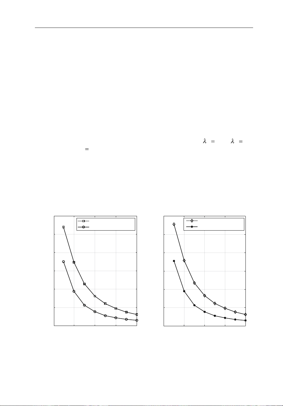
Backhauling with Massive-MIMO-Enabled mmWave Communication 49
H
5
A
100
a
3
(a) (b)
AP density (per sq. km)
Average user rate (in Gbps)
800
AP density (per sq. km)
Since mmWave transmission uses a wider channel bandwidth than microwave
transmission, the user rate will be higher for mmWave communication. The
comparison of average user rate between mmWave and microwave transmission
shown in Figure3.3 indicates that microwave transmission is unable to provide a
Gbps data rate to the user end as expected from 5G small‐cell networks. The mmWave
frequency can provide a multi‐Gbps data rate on average even for densely deployed
SBSs. We also observe that the user rate depends on the backhaul quota (Q
) or
h
maximum limit of the hubs. In Figure3.3, it is shown that a higher average user rate
can be achieved by increasing the backhaul quota which enables hubs to provide more
backhaul links to the APs.
To analyse the impact of association schemes on user rates, we compare the
downlink rates of all users for conventional nearest AP association and stable matching
association. Figure3.4 shows the total network rate and average user rates for different
backhaul quotas (Q
with AP quota
) and association schemes. Here, we consider
h
for simulation. We observe that when the competition for
and
AP–UE association is less for lower user density, the nearest AP association performs
better than the stable‐matching‐based association. As user density increases, the competition for association with the desired AP also increases. In such scenarios, the
overall user rate increases for the stable matching association when compared to the
distance‐dependent association due to several factors.
12
10
8
6
4
2
0
0 200 400 600 800
mmWave rate with Qh = 20
mmWave rate with Qh = 10
Figure3.3 Average user rate for (a) mmWave and (b) microwave access link with different
backhaul quotas (Qh)
300
250
200
150
100
Average user rate (in Mbps)
50
0
0 200 400 600
Microwave rate with Qh = 20
Microwave rate with Qh = 10
Page 62

50 Backhauling/Fronthauling for Future Wireless Systems
(a) (b)
User density (per sq. km) User density (per sq. km)
Rate of all users (in Gbps)
600
7000
6000
5000
4000
3000
2000
1000
100 200 300 400 500 600
Stable matching, Qh =20
Stable matching, Qh =10
Nearest AP association, Qh = 20
Nearest AP association, Qh = 10
Figure3.4 (a) Network rate and (b) average user rate for different user‐association schemes
In the case of distance‐dependent backhaul link association, densely deployed APs
compete to get associated with the nearest backhaul hub. The hub associates with the
APs according to the arrival of the association requests. Once the quota is exceeded,
the hub does not have the flexibility to alter the association even if it knows that a
better rate can be achieved. An AP cannot get backhaul connectivity if the nearest hub
is overloaded. Similarly, for access link association, the UEs send their association
requests to their nearest APs and get associated if the AP quota is not exceeded. When
the competition for user association increases, more users are rejected. Also, the
distance‐dependent association may result in poor SINR at the receivers in some
scenarios. For example, if the target AP’s nearest backhaul hub is NLOS or quite far
away, then downlink transmission to the AP may experience poor SINR.
On the other hand, stable matching is performed utilizing the channel state
information. The preference lists for hubs, APs and UEs are calculated based on the
rate information. During backhaul link association, the stable matching algorithm
allows the overloaded hub to recheck the ranking or the rates it can deliver to APs it
is currently associated with. The hub can update its association if it can provide a
better rate to the requesting AP. The stable matching algorithm also provides an
opportunity for an AP to apply to the next preferred hub if it is rejected by its most
preferred hub. The next preferred hub may be able to support this requesting AP with
a better rate. Consequently, this will allow the AP to serve more UEs in the network.
Similarly, the stable matching algorithm for the AP–UE association, which exploits
the channel state information, will also enable UEs to achieve better user rates at the
access links when compared to those with the nearest AP association.
25
20
15
10
Average user rate (in Gbps)
5
0
100 200 300 400 500
Stable matching, Qh =20
Stable matching, Qh =10
Nearest AP association, Qh = 20
Nearest AP association, Qh = 10
Page 63

Backhauling with Massive-MIMO-Enabled mmWave Communication 51
3.6 Conclusion
We have discussed wireless backhaul solutions for future 5G small‐cell networks.
In order to provide backhaul connectivity to a large number of SBSs in such a network in a cost‐effective way, mmWave spectrum is beneficial due to the ample
amount of unlicensed spectrum and high directivity. The performance of mmWave
propagation can be enhanced by using massive MIMO through installing a large
number of antennas in the backhaul system. We have described a tractable system
model for a massive‐MIMO‐enabled mmWave backhauling network. To maximize
the overall user rate, we have formulated a matching game which provides stable
matching association at the backhaul and access ends. Numerical results have
shown that the massive‐MIMO‐enabled mmWave backhaul solution provides a reliable SINR coverage probability and the use of mmWave in the access link increases
the average user rate compared to traditional microwave. Analysis of the stable
matching user association has shown that channel‐state‐aware matching can provide a better user rate compared to distance‐dependent user association in a dense
small‐cell network.
The insights from the results motivate the design of a backhaul‐aware user
association scheme so that the overall network is maximized in a dense small‐cell
network. To improve the network performance further, massive MIMO can be incorporated at the APs so that more users can be served simultaneously with higher
antenna gain.
Acknowledgement
This work was supported by the Natural Sciences and Engineering Research Council
of Canada (NSERC).
References
[1] Andrews, J. G., Buzzi, B., Choi, W., Hanly, S. V., Lozano, A., Soong, A. C. K. and Zhang, J. C.
(2014) What will 5G be?. IEEE Journal on Selected Areas in Communication, 32(6), 1065–1082.
[2] Rangan, S., Rappaport, T. and Erkip, E. (2014) Millimeter‐wave cellular wireless networks:
Potentials and challenges. Proceedings of the IEEE, 102(3), 366–385.
[3] Marzetta, T. L. (2010) Noncooperative cellular wireless with unlimited numbers of base station
antennas. IEEE Transactions on Wireless Communications, 9(11), 3590–3600.
[4] Siddique, U., Tabassum, H., Hossain, E. and Kim, D. I. (2015) Wireless backhauling of 5G small
cells: Challenges and solution approaches. IEEE Wireless Communications, Special Issue on ‘Smart
Backhauling and Fronthauling for 5G Networks’, 22(5), 22–31.
[5] Interdigital (2013) ‘Small Cell Millimeter Wave Mesh Backhaul.’ White paper. Interdigital,
Wilmington, DE, USA. Available at: http://goo.gl/Dl2Z6V.
[6] Li, Y., Pappas, N., Angelakis, V., Pioro, M. and Yuan, D. (2015) Optimization of free space optical
wireless network for cellular backhauling. IEEE Journal on Selected Areas in Communication,
33(9), 1841–1854.
Page 64

52 Backhauling/Fronthauling for Future Wireless Systems
[7] Demers, F., Yanikomeroglu, H. and St‐Hilaire, M. (2011) A survey of opportunities for free space
optics in next generation cellular networks. In Proceedings of the Communication Networks and
Services Research Conference, pp. 210–216, May.
[8] Zhao, Q. and Li, J. (2006) Rain attenuation in millimeter wave ranges. In Proceedings of the IEEE
International Symposium on Antennas, Propagation and EM Theory, pp. 1–4, October.
[9] Rappaport, T., Sun, S., Mayzus, R., Zhao, H., Azar, Y., Wang, K., Wong, G., Schulz, J., Samimi, M.
and Gutierrez, F. (2013) Millimeter wave mobile communications for 5G cellular: It will work!
IEEE Access, 1, 335–349.
[10] Daniels, R. C. and Heath, R. W. (2007) 60 GHz wireless communications: Emerging requirements
and design recommendations. IEEE Vehicular Technology Magazine, 2(3), 41–50.
[11] Roh, W., Seol, J., Park, J., Lee, B., Lee, J., Kim, Y., Cho, J., Cheun, K. and Aryanfar, F. (2014)
Millimeter‐wave beamforming as an enabling technology for 5G cellular communications:
Theoretical feasibility and prototype results. IEEE Communications Magazine, 52(2), 106–113.
[12] Rappaport, T. S., Murdock, J. N. and Gutierrez, F. (2011) State of the art in 60‐GHz integrated
circuits and systems for wireless communications. Proceedings of the IEEE, 99(8), 1390–1436.
[13] Dussopt, L., Bouayadi, O. E., Luna, J. A. Z., Dehos, C. and Lamy, Y. (2015) Millimeter‐wave
antennas for radio access and backhaul in 5G heterogeneous mobile networks. European Conference
on Antennas and Propagation, pp. 1–4, April.
[14] Bai, T. and Heath, R. W. (2014) Asymptotic coverage probability and rate in massive MIMO net-
works. In Proceedings of the IEEE GlobalSIP, pp. 602–606, December.
[15] Xiang, Z., Tao, M. and Wang, X. (2014) Massive MIMO multicasting in noncooperative cellular
networks. IEEE Journal on Selected Areas in Communication, 32(6), 1180–1193.
[16] Liu, A. and Lau, V. (2014) Hierarchical interference mitigation for massive MIMO cellular net-
works. In IEEE Transactions on Signal Processing, 62(18), 4786–4797.
[17] Kammoun, A., Muller, A., Bjornson, E. and Debbah, M. (2014) Low‐complexity linear precoding
for multi‐cell massive MIMO systems. In Proceedings of EUSIPCO, pp. 2150–2154, September.
[18] Hur, S., Kim, T., Love, D. J., Krogmeier, J. V., Thomas, T. A. and Ghosh, A. (2013) Millimeter
wave beamforming for wireless backhaul and access in small cell networks. IEEE Transactions on
Communication, 61(10), 4391–4403.
[19] Wireless 20/20 (2012) ‘Rethinking Small Cell Backhaul: A Business Case Analysis of Cost‐
Effective Small Cell Backhaul Network Solutions.’ White paper, July. Available at: http://www.
wireless2020.com/docs/RethinkingSmallCellBackhaulWP.pdf
[20] Taori, R. and Sridharan, A. (2015) Point‐to‐multipoint in‐band mmWave backhaul for 5G net-
works. IEEE Communications Magazine, 53(1), 195–201.
[21] Niu, Y., Gao, C., Li, Y., Su, L., Jin, D. and Vasilakos, A. V. (2015) Exploiting device‐to‐device
transmissions in joint scheduling of access and backhaul for small cells in 60 GHz band. IEEE
Journal on Selected Areas in Communication, 33(10), 2052–2069.
[22] Singh, S., Kulkarni, M. N., Ghosh, A. and Andrews, J. G. (2015) Tractable model for rate in self‐
backhauled millimeter wave cellular networks. IEEE Journal on Selected Areas in Communication,
31(10), 2196–2211.
[23] Coldrey, M., Koorapaty, H., Berg, J., Ghebretensa, Z., Hansryd, J., Derneryd, A. and Falahati, S.
(2012) Small‐cell wireless backhauling: A non‐line‐of‐sight approach for point‐to‐point microwave
links. In Proceedings of the IEEE Vehicular Technology Conference, pp. 1–5, September.
[24] Alkhateeb, A., Mo, J., Gonzalez‐Prelcic, N. and Heath, R. W. (2014) MIMO precoding and
combining solutions for millimeter‐wave systems. IEEE Communications Magazine, 52(12),
122–131.
[25] Gao, Z., Dai, L., Mi, D., Wang, Z., Imran, M. A. and Shakir, M. Z. (2015) MmWave massive‐
MIMO‐based wireless backhaul for the 5G ultra‐dense network. IEEE Wireless Communications,
22(5), 13–21.
Page 65

Backhauling with Massive-MIMO-Enabled mmWave Communication 53
[26] Wang, N., Hossain, E. and Bhargava, V. K. (2015) Backhauling 5G small cells: A radio resource
management perspective. IEEE Wireless Communications, 22(5), 41–49.
[27] Zheng, K., Zhao, L., Mei, J., Dohler, M., Xiang, W. and Peng, Y. (2015) 10Gbps‐HetSNets with
millimeter‐wave communications: Access & networking challenges and protocols. IEEE
Communications Magazine, 53(1), 222–231.
[28] Bai, T., Vaze, R. and Heath, R. W. (2014) Analysis of blockage effects on urban cellular networks.
IEEE Transactions on Wireless Communication, 13(9), 5070–5083.
[29] Bai, T. and Heath, R. W. (2015) Coverage and rate analysis for millimeter‐wave cellular networks.
IEEE Transactions on Wireless Communication, 14(2), 1100–1114.
[30] Hunter, A., Andrews, J. and Weber, S. (2008) Transmission capacity of ad hoc networks with
spatial diversity. IEEE Transactions on Wireless Communication, 7(12), 5058–5071.
[31] Bethanabhotla, D., Bursalioglu, O., Papadopoulos, H. C. and Caire, G. (2014) User association and
load balancing for cellular massive MIMO. In Proceedings of Information Theory and its
Applications (ITA), pp. 1–10, February.
[32] Roth, A. E. and Sotomayor, M. A. O. (1992) Two‐sided matching: A study in game‐theoretic mod-
eling and analysis, Cambridge University Press, pp. 485–541.
[33] Jorswieck, E. (2011) Stable matchings for resource allocation in wireless networks. In Proceedings
of the 17th International Conference on Digital Signal Processing (DSP), pp. 1–8, July.
[34] Semiari, O., Saad, W., Dawy, Z. and Bennis, M. (2015) Matching theory for backhaul management
in small cell networks with mmWave capabilities. In Proceedings of the IEEE ICC, pp. 3460–3465,
June.
[35] Sekander, S., Tabassum, H. and Hossain, E. (2015) A matching game for decoupled uplink–down-
link user association in full‐duplex small cell networks. In IEEE Globecom’15, December.
Page 66

4
Fronthaul foraFlexible
Centralization inCloud Radio
Access Networks
Jens Bartelt,1 Dirk Wübben,2 Peter Rost,3 Johannes Lessmann4
andGerhardFettweis
1
Technische Universität Dresden, Dresden, Germany
2
University of Bremen, Bremen, Germany
3
Nokia Networks, Munich, Germany
4
NEC Laboratories Europe, Heidelberg, Germany
4.1 Introduction
The architecture of fourth generation (4G) mobile networks, for example 3GPP long‐term
evolution (LTE), is organized in a decentralized way, such that the complete baseband
processing including the physical (PHY) layer, medium access (MAC) layer and parts
of the network layer processing are performed at the base stations (BSs). Internet
Protocol (IP)‐layer user data are then forwarded between the BS and the network
core, which requires a relatively modest transport network, usually known as the
backhaul (BH) network.
An alternative to this decentralized concept is to centralize radio access network
(RAN) functionalities. First introduced in [1], the so‐called centralized‐RAN or
cloud‐RAN (C‐RAN) architecture proposes to reduce the functionality of BSs to so‐
called remote radio heads (RRHs), which only perform analogue processing and
forward digital samples between the RRH and centralized baseband units (BBUs).
Such a centralized architecture is already utilized in some 4G networks and is actively
1
Backhauling/Fronthauling for Future Wireless Systems, First Edition.
Edited by Kazi Mohammed Saidul Huq and Jonathan Rodriguez.
© 2017 John Wiley & Sons, Ltd. Published 2017 by John Wiley & Sons, Ltd.
Page 67

56 Backhauling/Fronthauling for Future Wireless Systems
being considered for future mobile networks as it offers several advantages. First
among these advantages is a reduction in operational and capital expenditure. By
reducing the size, the sites can be smaller and the energy consumption can be reduced,
particularly because no active cooling is required. As all BBUs are located in a
centralized location, maintenance also becomes much easier.
Next, the centralization of BBUs makes cooperative processing techniques much
easier to implement. Techniques such as coordinated multi‐point (CoMP) [2, 3] or
multi‐point turbo detection (MPTD) [4] require an extensive exchange of signals
between BSs and suffer heavily from delays on BH links. Hence, they are much easier
to implement if all signals are forwarded and processed in a centralized BBU.
Finally, current advances in processor technology and virtualization have enabled
the implementation of baseband processing on general‐purpose processors (GPPs).
The early deployments of C‐RAN utilized centralized BBUs composed of dedicated
hardware such as ASICs (application‐specific integrated circuits), FPGAs (field‐
programmable gate arrays) and DSPs (digital signal processors). However, this
approach merely amounts to a physical separation of the analogue front‐ends from
the digital basebands that would be co‐located in the decentralized architecture. As
a result, a separate BBU is required per BS and signals need to be exchanged between the BBUs, which still makes joint processing difficult. More recent approaches
[5] therefore advocate the use of more flexible GPPs, commonly found in PCs or
servers. Thereby, virtualization and the concept of cloud computing as used in the
IT industry [6] can be facilitated. While this further simplifies maintenance, upgrades
and organization, it also introduces the economy of scale, as standardized hardware
can be used, further lowering capital expenditure (CAPEX). Additionally, virtualization allows balancing processing load between the different BSs according to
their load variations, thereby lowering the total processing power that needs to be
deployed.
These benefits of C‐RAN come at the price of a demanding transport network. In
the C‐RAN architecture, the transport network forwards samples between the BBUs
and the RRHs, and is commonly known as the fronthaul (FH) network. In order to
enable efficient, centralized and cooperative processing, the FH network must offer a
huge capacity and low total latency and jitter. In fact, if not dimensioned correctly, the
FH network could become a bottleneck for the performance of future networks.
Furthermore, FH networks are very expensive to deploy, thus making a simple overprovisioning not economically viable. Several approaches have been investigated to
reduce these FH requirements, for example by compressing FH data [7] or reducing
costs by a joint optimization of the RAN and BH/FH network [8]. In this chapter, we
want to describe another promising approach to address the FH challenge in future
networks: a flexible centralization of RAN functionality [5, 9]. As indicated above,
the current fully decentralized or fully centralized architectures are two extreme
approaches. Utilizing a flexible functional split, a part of the baseband processing
would be located in the BS and another in a centralized processing unit. In this chapter,
Page 68
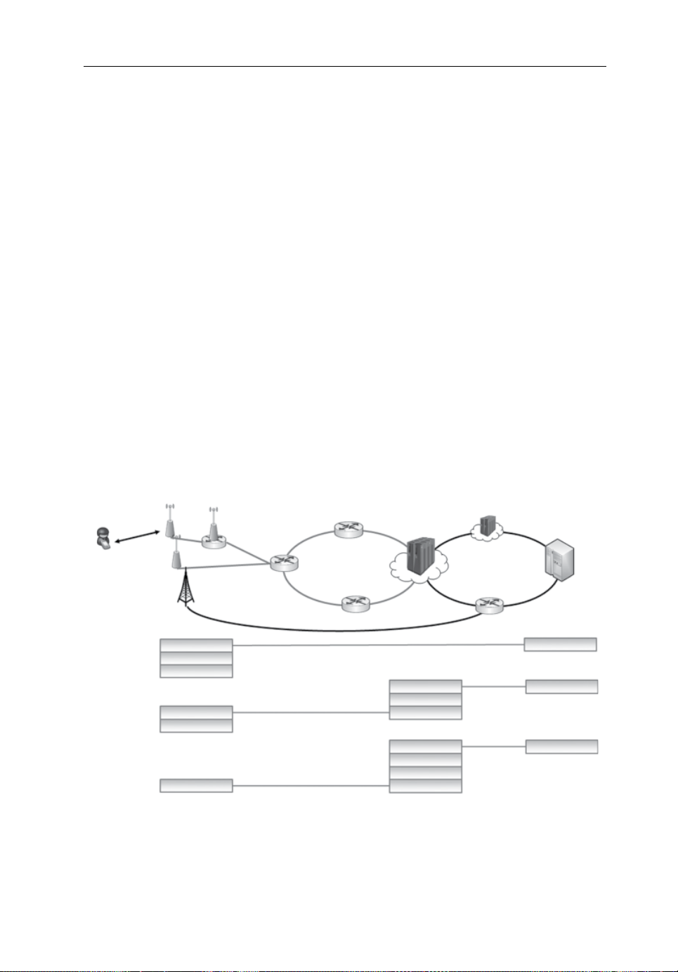
Fronthaul for a Flexible Centralization in C-RANs 57
User Radio
Base
Fronthaul
Fronthaul
Cloud
Backhaul Core
we will discuss how this approach can reduce the requirements on the FH network
while still partially maintaining the benefits of centralization [10]. For this, we will
first introduce the considered network architecture and explain different options for a
flexible centralization. We will further describe the technologies that will help to
enable this approach, and describe how such a flexible split calls for a convergence of
the FH and BH network to a unified transport network.
4.2 Radio Access Network Architecture
Figure4.1 shows the architecture of a contemporary mobile network and illustrates
the difference between fully decentralized, fully centralized and flexible architectures. Users (called user equipment (UE) in LTE) are located on the edge of the network and ultimately want to communicate with the core on the other edge of the
network. The core then routes the traffic to the destination via gateways, and is also
responsible for network management and policy control. To reach the core, the UE
communicates with a BS via a RAN link. In a fully decentralized network, the BS
performs baseband processing on the PHY layer and MAC layer as well as packet
data convergence (PDCP, packet data convergence protocol). The traffic can then be
forwarded as IP packets over BH links to the core. In the fully centralized architecture,
access
station
MAC+PDCP
architecture
Decentralized
Flexible
architecture
Centralized
IP
PHY
FH
PHY
‘last mile’
aggregation
processing
centre
IP
MAC+PDCP
FH
IP
MAC+PDCP
PHY
CPRICPRI
IP
IP
IP
Figure4.1 System architecture and protocol stack of decentralized, exible and centralized
networks
Page 69

58 Backhauling/Fronthauling for Future Wireless Systems
by contrast, all PHY, MAC and PDCP processing is performed not at the BS but in a
cloud processing centre, which is connected to the core via BH. The cloud processing
centre exchanges digital samples with the BS over the FH, usually using the Common
Public Radio Interface (CPRI) [11] standard. The FH can be separated into an
aggregation network that collects and distributes data to many BSs, and the so‐called
‘last mile’ that represents the final link to the BSs. For the FH as well as for the BH,
a number of topologies (star, chain, ring and tree) can be used [12].
The two currently used concepts of either fully decentralized or fully centralized
baseband processing are the two extreme sides of a basic trade‐off. The more
processing is centralized, the easier it is to implement cooperative processing, the
higher are the potential gains in cost savings, and the easier are maintenance and
upgrading. This is traded off with a demanding and expensive FH network. The
decentralized approach, on the other hand, requires a much simpler BH network but
makes the aforementioned operations much more difficult or expensive. For future
mobile network architectures, it therefore makes sense to look at intermediate options
that still offer high centralization gains but at reduced FH requirements. In the next
section, four of these intermediate split options that offer a large reduction in FH
requirements will be described.
4.3 Functional Split Options
Figure4.2 shows the more detailed PHY layer signal processing chain in the BS of a
typical mobile network, using the example of LTE [13]. In the downlink (DL), the
MAC layer user data are first encoded for forward error correction (FEC) before
being modulated and precoded. These operations are performed according to the
current channel quality and channel state, which have to be made available by measurements. Next, the user and control data are mapped to the physical resources, for
example, subcarriers and time slots, thereby multiplexing different logical channels,
for example, control and data channels. Additional signals for synchronization and
channel measurements are added at this stage as well. In LTE, this resource mapping
is performed in the frequency domain. After transforming the signal to the time
domain, a cyclic prefix (CP) is added and the data are digitally filtered. Finally, the
data are D/A converted, up‐converted to the carrier frequency and then transmitted
via the antennas.
In the uplink (UL), the process is reversed. The radio frequency signal received
from the UEs is first down‐converted to baseband, then digitized by sampling and
quantization and digitally filtered. After the CP has been removed, the data are transformed to the frequency domain, where the different channels are demapped from the
physical resources and the signals are equalized. After converting the signals back to
the time domain, the symbols are detected and decoded. The resulting MAC data are
then forwarded to the higher layers. In this work, we will view the hybrid automatic
Page 70

Fronthaul for a Flexible Centralization in C-RANs 59
Downlink
Centralized
MAC-layer
processing
FEC encoding / decoding
Mod. + precoding / detection + equal.
Split D
Split C
Split B
Local
processing
IFFT + mapping / FFT+demapping
Split A
D/A conv. + filtering / A/D conv.
Radio frequency processing
Antenna
Uplink
Figure4.2 Functional split options. Reproduced from [10] with permission from the IEEE
repeat request (HARQ) as part of the decoding process, although it is often seen as
part of the MAC layer.
Within this processing chain, four options of splitting the processing between the
BS and the central processing unit are very promising. These are indicated in
Figure4.2 as split options A–D.
Split option A corresponds to the split used in C‐RAN as implemented today. The
FH interface for this split is standardized in CPRI [11]. In the DL, the complete
baseband processing is performed centrally and digital samples are forwarded to
theBSs. In the UL, conversely, the received signals are only digitized, filtered and
then forwarded. As all baseband processing is centralized, there is no drawback in
terms of what types of joint processing can be performed.
In split option B, the mapping/demapping is decentralized. In the DL, this means
that the user and control data are forwarded separately and in the frequency domain.
Synchronization and reference signals can be either forwarded from the central
processing unit to the BSs or they may be generated and added at the BS. The different signals are combined at the BS, converted to the time domain and the CP is added
before it is D/A converted. In the UL, the CP is removed, the signals are converted
to the frequency domain and the separate channels are demapped at the BS.
Page 71

60 Backhauling/Fronthauling for Future Wireless Systems
Synchronization and channel estimation can either be performed at the BS or centrally. Due to the fact that the decentralized processing mainly involves transforming
and restructuring the received signal, all types of cooperative processing can still be
performed centrally without any disadvantage. However, for split B and all subsequent
splits, digital processing resources are required at the BS, which makes them bigger
and more power‐hungry.
For split option C, modulation and precoding are also decentralized in the DL.
Accordingly, bit data instead of complex amplitude samples need to be forwarded
from the central processing unit to the BS. In the UL, equalization and demodulation
are performed at the BSs so that soft information on user bits, for example, log‐
likelihood ratios (LLRs), needs to be forwarded to the central processing unit. As
detection is now performed decentrally, techniques like CoMP or MPTD can no
longer be performed easily, so this split does not offer as many centralization gains as
the previous ones. Still, techniques like, for example, joint decoding [14] can be performed centrally. Also, techniques such as in‐network processing have been proposed
[15] that enable a decentralized, yet joint detection. However, these methods require
extensive inter‐BS links to exchange signals, thereby again increasing the requirements of the FH.
In split option D, coding and decoding are also performed decentrally, that is, all
PHY‐layer processing is performed at the BSs. Accordingly, centralization gains can
only come from higher‐layer processing. Techniques like joint scheduling [16] and
connection control [17] still offer benefits from such a partly centralized architecture.
However, the requirements of these higher‐layer splits are very similar to those of
split D.
4.4 Requirements ofFlexible Functional Splits
The main benefit of an only partial centralization is the reduced requirements on the
FH network in terms of data rate, latency and jitter. In the following, the requirements
of the four introduced split options will be discussed. While the required data rates
can be relatively easily derived, the requirements on latency and jitter are difficult to
estimate, as they depend on numerous physical parameters as well as standardization
and implementation aspects. The data rates in this section are derived for a single
sector and a single carrier/frequency band. If a site incorporates multiple sectors and
carriers–as is quite common in today’s network–the data rates scale linearly with
that number. This is sometimes identified as the number of ‘sector‐carriers’.
Furthermore, LTE is used as a baseline technology, as it has the most demanding
requirements when compared to third generation (3G) and second generation (2G)
technologies. However, the derivations of other previous or future standards are
expected to be very similar. Some numerical examples for contemporary and future
networks are given at the end of this section.
Page 72

Fronthaul for a Flexible Centralization in C-RANs 61
DNfN
2
4.4.1 Split A
Split A marks the limit between analogue and digital signals. Accordingly, the data
exchanged via the FH correspond to digitized I/Q samples and the data rate required
for split option A in bit/s can be calculated as follows:
where N
AAsQA,,
is the number of antennas, fs is the sampling frequency and N
A
(4.1)
is the reso-
Q,A
lution of the quantizer in bits. The factor 2 accounts for the I‐ and Q‐ phase of the
signal and γ is the overhead introduced by the FH, that is the overhead of line coding
or an FEC, or additional control signals. The number of antennas N
indicates that a
A
separate data stream needs to be fronthauled for each antenna, while the sampling
frequency f
accounts for the system’s bandwidth. The quantizer resolution N
s
Q,A
and
the factor 2 account for the word length per digital sample.
The dependence on the number of antennas N
of this split may become critical
A
in future mobile networks, when massive multiple‐input/multiple‐output (MIMO)
techniques [18] with 100 or more antenna elements may be introduced, as this linearly
scales up the FH data rate. Similarly, f
depends on the total bandwidth, which is also
s
foreseen to increase in future networks. The quantizer resolution needs to be quite
high, usually around 15 bits per dimension, due to the high dynamics of the time
domain signal in LTE [19]. However, the main disadvantage of this split is the fact
that it does not depend on the actual user traffic, that is even when no user is connected
to the BS, the full FH data rate needs to be forwarded.
In terms of latency, CPRI defines a maximum round‐trip time of 5 microseconds
(µs) for processing, which is added to the propagation time to amount, typically, to a
few hundred µs. According to the standard, this is mainly motivated by the inner loop
power control for the UL in UTRAN (universal terrestrial radio access network, the
mobile network of 3G) [11]. To compensate for the fast fading and near–far effects,
the latency must be in the order of the coherence time of the channel, which can be as
low as one millisecond (ms) for fast users in current 4G systems. As the coherence
time decreases with higher carrier frequencies, the requirements can be expected to
be even stricter in 5G systems which utilize millimetre‐wave (mmWave) frequencies.
Other works [19, 20] state that the time allowed in LTE for HARQ acknowledgements is the most critical latency constraint. The UE expects an acknowledgment
after 3 ms. When subtracting the time typically required for baseband processing, this
leaves a few hundred ms for the FH. However, this is a direct result of the LTE standard and not of physical constraints, and thus could be modified in future standards.
For split C, we describe methods for mitigating the delay requirement of HARQ.
In order to enable CoMP and distributed MIMO techniques, samples of different
BSs need to be correctly aligned and the timing advance, that is, the different propagation times of different UEs, need to be known precisely. For this, the total delay on
Page 73

62 Backhauling/Fronthauling for Future Wireless Systems
D
BASC SF QB
,
1
2
,
NSC1200
the FH must be measured and jitter must not be too high. Hence, the accuracy of the
timing measurements and the jitter need to be in the order of magnitude of the sample
duration, that is, a few tens of nanoseconds (ns) for LTE. In future networks utilizing
bandwidths in the GHz range, these requirements will increase still further as the
sample duration decreases. This could lead to a maximum tolerable jitter in the order
of hundreds of picoseconds.
4.4.2 Split B
The data exchanged when utilizing split option B corresponds to frequency domain
samples. Additionally, the different physical channels are separately available. These
different channels carry data responsible for, for example, synchronization, channel
estimation, control signals or user data. Some of these channels, for example,
synchronization and reference symbols, do not have to be fronthauled as they can be
generated at the BSs. These signals do not benefit from centralized processing and
can be calculated based on a few parameters like the cell identifier, which can be
assigned permanently. The required data rate for split B can be calculated as:
where N
frame, T
N
Q,B
is the number of utilized subcarriers, NS is the number of symbols per
SC
is the frame duration, η the percentage of actually occupied resources and
F
the number of quantization bits per sample for this split. NSC points to the fact
NN NT N
(4.2)
that usually guard carriers are used to avoid interference with neighbouring bands. As
they do not carry any data, they can be added after/discarded during the mapping/
demapping process. To give an example, a 20 MHz LTE system has 2048 subcarriers
in total, of which 848 are used as guard bands, leading to
riers. Similarly, N
is the number of symbols that carry user or control channels, as
S
utilized subcar-
synchronization and reference signals also potentially do not have to be forwarded
between the BS and the central processing unit. The load factor η accounts for the fact
that before/after mapping/demapping only those physical resources need to be forwarded that actually carry user data, that is, if the BS is only 50% loaded, the FH data
will also be reduced by a factor of 2. As the dynamics of the frequency domain signal
are much lower compared to time domain signals, the number of bits per sample N
Q,B
can be reduced to 7–9 bits [19], thereby further reducing the FH data rate.
Split B offers the option of performing channel estimation decentrally, as the reference symbols are available after demapping. This would remove the power control
constraints on the latency for this split, as the signal-to-interference-plus-noise ratio
(SINR) could be calculated in the BS. However, the centralized precoding still
requires that up‐to‐date channel information is available at the central processing
unit. As a consequence, the latency requirements could be slightly relaxed, depending
Page 74

Fronthaul for a Flexible Centralization in C-RANs 63
DN
TM
CLSC SF QC
,
1
2
log
,
on the coherence time of the channel. Jitter is less critical for the higher‐layer splits,
as the samples are aligned at the BS. Still, processing in the central unit can only start
once the symbols from all BSs are available. While the symbols can be buffered to
compensate for different latencies, a high difference in arrival times of different BSs
would lead to a large latency.
4.4.3 Split C
Split C is the only split that exhibits a significant asymmetry between UL and DL. In
the DL, encoded user bits are transported, while in the UL, LLR values have to be
forwarded to enable turbo decoding. Still, the required data rate for both UL and DL
can similarly be calculated as:
where N
NN
is the number of layers (spatial streams), M is the modulation order and N
L
N
(4.3)
Q,C
is the number of quantization bits for split C.
The difference between UL and DL lies in N
. In the DL, only encoded user bits
Q,C
are forwarded, so the number of bits per symbol is coupled to the utilized modulation
scheme, that is 2 bits for 4‐QAM, 4 for 16‐QAM and so on. In the UL, one LLR per
information bit has to be forwarded and each LLR is typically represented by 3 bits,
that is, 6 bits for 4‐QAM, 12 bits for 16‐QAM and so on.
The main advantage of this split is that the number of antennas is mapped to spatial
streams and vice versa. To give an example, if a BS is equipped with four antennas but
due to the channel state can only transmit one spatial stream to a user, only this one
stream has to be forwarded instead of one stream for each of the four antennas. This will
become of importance in massive MIMO systems [18], when a high number of antennas
is mostly used for beamforming, and only a limited number of independent user streams
are transmitted. Both the number of layers and the modulation scheme depend on the
current channel quality of a certain user. These two dependencies result in the fact that
the FH traffic is even more coupled with the actual user traffic, that is, when a user faces
bad channel conditions and can transmit only little data, this is reflected in the FH traffic.
As channel decoding is still performed centrally, the HARQ scheme of LTE can be
limiting, as UEs require an acknowledgement to be sent within 3 ms, so split C needs
to meet that latency requirement. To overcome this, local feedback schemes have
been proposed [21] in which the BSs send feedback without waiting for confirmation
about the decoding outcome from the central processing unit. However, this will
reduce the performance to some degree. Alternatively, it has been proposed to suspend the HARQ process if the acknowledgement cannot be sent in time and simply
not schedule new traffic until the decoding is finished [19]. For future systems,
increasing the allowed HARQ delay could also be considered. However, this requires
Page 75

64 Backhauling/Fronthauling for Future Wireless Systems
DLSC SF cQD
,
1
2
log
,
higher available memory resources at the UEs, as the data of the different HARQ
processes will have to be kept until the acknowledgement arrives.
4.4.4 Split D
Using split D, bit‐level user data are transported and thus correspond very closely to
what is considered classical BH in current networks. The required data rate can be
calculated as:
where R
DNNNTMRN
is the code rate and N
c
is the number of quantization bits for this split.
Q,D
(4.4)
Coding/decoding adds/removes redundant bits to/from the actual information bits.
These redundant bits do not have to be forwarded in this split, which further decreases
the FH data rate. Also, the code rate is coupled to the channel quality and therefore to
the actual user traffic. As information bits are forwarded, the number of quantization
bits can be set to one for this split.
Split D terminates PHY‐layer processing. Hence, the latency requirement is determined by the higher layers. If centralized scheduling is performed and intended to
exploit time diversity, the latency must be small enough to follow the fading of the
channel. Otherwise it can be relaxed to the application‐layer requirements which are
typically in the order of a few tens of ms.
4.4.5 Summary andExamples
Table 4.1 summarizes the main parameters that determine the requirements of the
different splits.
The different data rate requirements are further illustrated in Figure 4.3. The
requirements for the four different splits are depicted for four different parameter sets.
The baseline is a 4G system, that is, LTE, which is further differentiated in a maximum
data rate, utilizing the highest parameters possible and an exemplary parameter set
using more representative values. The exemplary parameter set was chosen to illustrate additional reductions in data rate that would not be visible in the maximum data
rate. To give a few examples, the maximum load of a BS is 100%, while in real
deployments such a utilization would actually indicate a capacity problem of the network as a BS should be loaded less than 100%. Similarly, the maximum code rate is
1.0 (i.e., uncoded transmission), while real systems have to employ a lower code rate
according to the channel quality.
As we discussed previously, the requirements are expected to increase in future
networks mainly through three advancements: the introduction of massive MIMO and
the utilization of higher carrier frequencies and bandwidths. Accordingly, Figure4.3
Page 76
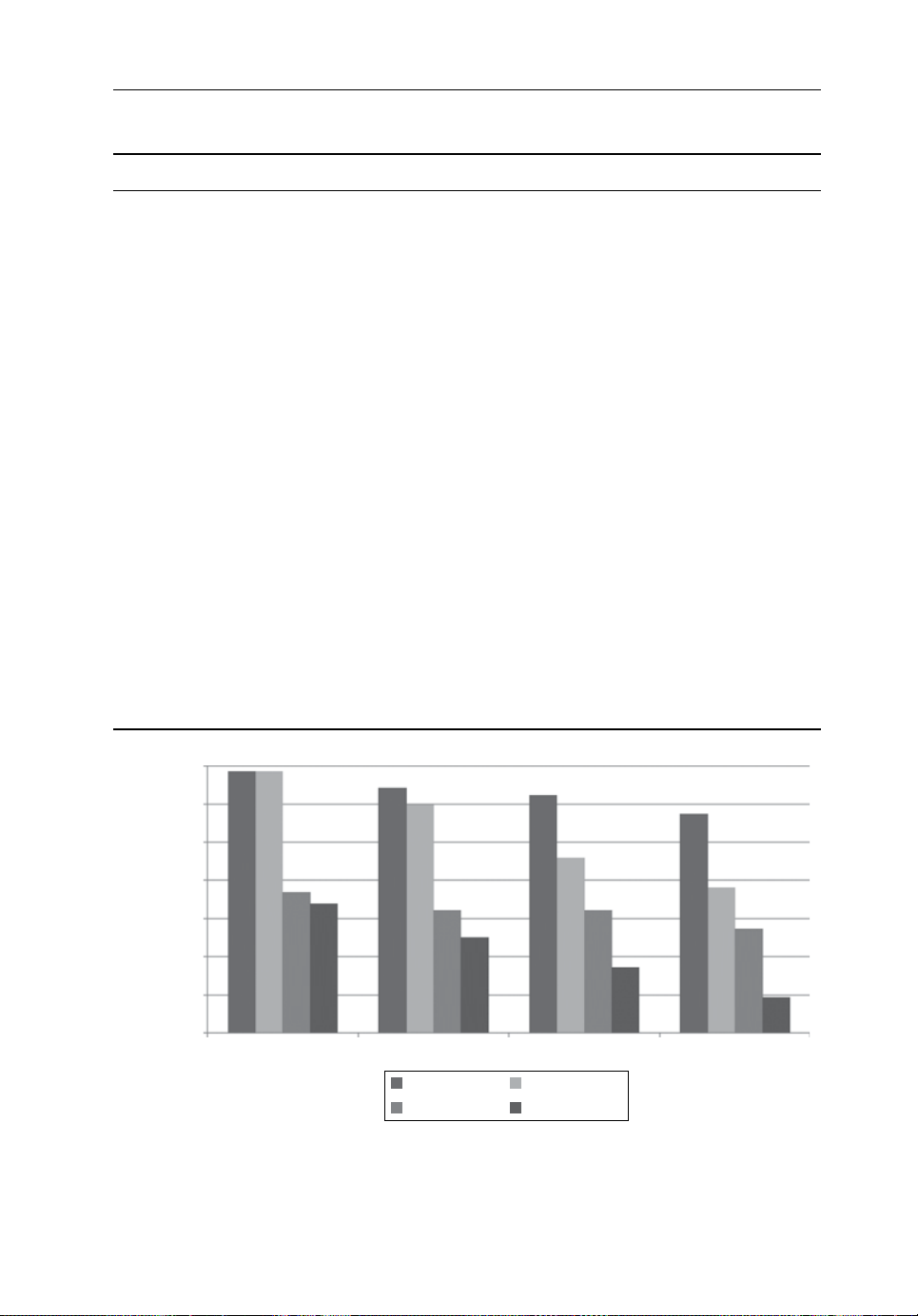
Fronthaul for a Flexible Centralization in C-RANs 65
Data rate
Table4.1 Parameters impacting FH requirements fordifferent functional splits
Split Data rate Latency Jitter
A
• Number of antennas
• Bandwidth
• Quantization in time
domain (high number of
bits)
B • Number of antennas
• Number of utilized
subcarriers
• Load
• Quantization in fre-
quency domain (low
number of bits)
C • Number of spatial layers
• Load
• Modulation order
• Number of quantization
bits 1 (DL) or 3 (UL)
D • Number of spatial layers
• Load
• Modulation order
• Code rate
• Channel coherence time
• UL power control needs
to be able to follow fast
fading
• Channel coherence time
• Precoding must be able
to follow channel
• Maximum delay of
HARQ
acknowledgement
• Requirements of
higher‐layer applications
• For joint scheduling,
channel coherence time
can still be determining
factor
• Sample duration
• Timing advance
needs to be measured exactly
• Queueing should not
lead to increased
total latency
• Queueing should not
lead to increased
total latency
• Queueing should not
lead to increased
total latency
1 Tbps
1 Gbps
1 Mbps
7.2 Tbps
7.2 Tbps
4.9 Gbps
2.5 Gbps
Split A Split B
2.7 Tbps
5G maximum
4G maximum
960 Gbps
1.6 Gbps
311 Mbps
5G exemplary
4G exemplary
1.7 Tbps
52 Mbps
38 Gbps
1.6 Gbps
Split C Split D
560 Gbps
6.4 Gbps
538 Mbps
8.6 Mbps
Figure 4.3 Data rate requirements of different functional splits for current and future
networks
Page 77

66 Backhauling/Fronthauling for Future Wireless Systems
also shows data rates for a potential 5G system with 100 antennas and a sampling
frequency of 1.5 GHz. As higher‐order modulation schemes are also under discussion,
1024‐QAM was assumed. To account for the lower symbol distance in 1024‐QAM, a
higher quantizer resolution was also taken into account. The full list of parameters can
be found in Table4.2. In rows where only one parameter is listed, the exemplary and
maximum values are identical.
From the chosen parameters it is obvious that a potential 5G system would further
increase the already demanding requirements. In particular, the scaling with number
of antennas illustrates clearly that a full centralization with per‐antenna backhauling
is infeasible. In fact, the data rate is increased by more than three orders of magnitude.
While it can be expected that transport network technologies will also advance in the
future, such an increase cannot be expected in the timeframe considered for 5G mobile networks. It can be further seen from Figure4.3 that while the higher‐layer splits
lead to a reduction in general, there is also an important difference between the
maximum possible data rate and the exemplary rate. This difference is discussed in
detail in Section4.5.
Furthermore, Table4.3 shows the impact of higher carrier frequencies, larger bandwidth and higher UE speeds on the channel coherence time and sample duration,
which, in turn, determine the maximum tolerable delay and the delay accuracy for a
fully centralized system (split A), respectively. From the forecast numbers for a 5G
system, it is clear that these requirements would be even more challenging to fulfil
than those of a 4G system.
Table4.2 Parameters forthecalculation ofdata rate requirements
Symbol Description 5G max. / exemplary 4G max. / exemplary
N
A
N
L
Number of antennas 100 / 100 4 / 2
Number of spatial
50 / 8 4 / 1
layers
N
SC
N
S
Number of subcarriers 60 k / 50 k 1200 / 1080
Number of data
14 / 12 14 / 12
symbols per frame
f
s
Sampling frequency
1.5 GHz 30.72 MHz
(bandwidth)
N
Q
Number of quantiza-
18, 12, 3, 1 bit 15, 9, 3, 1 bit
tion bits per I / Q
dimension for split A,
B, C, D
γ FH overhead 1.33 1.33
T
F
Frame duration 1 ms 1 ms
η Utilization (load) 1.0 / 0.5 1.0 / 0.5
M Modulation order 1024 / 16 64 / 4
R
c
Code rate 1.0 / 0.5 1.0 / 0.5
Page 78

Fronthaul for a Flexible Centralization in C-RANs 67
N mM
L
,, log
2
c
C
s
Table4.3 Delay requirements of4G andexemplary 5G systems forsplit A
Parameter 4G 5G
Carrier frequency f
Max. UE speed v 250 km/h 500 km/h
Channel
coherence time/max. delay
023.4
(
Bandwidth 20 MHz 1 GHz
Sampling rate f
Sample duration/delay
accuracy
vf
C
) [22]
s
2 GHz 70 GHz
914 µs 13 µs
30.72 MHz 1.5 GHz
32.6 ns 0.67 ns
4.5 Statistical Multiplexing inaFlexibly Centralized Network
The previous section observed how a flexible split in general reduces the data rate
requirements by not forwarding certain parts of the signal. One main disadvantage of
split A, which corresponds to the currently used split in C‐RAN, is identified with the
fact that the FH data rate is always constant and does not vary with the actual user
traffic. With higher‐layer splits, this coupling is progressively increased, which gives
rise to another important aspect of a flexible functional split: the statistical multiplexing gain.
As described in Section4.2, FH networks typically consist of two parts: the so‐
called ‘last mile’ that connects the individual BSs and an aggregation, or ‘metro’,
network that aggregates that traffic from numerous BSs and forwards it to the core
network. The observations made in Section4.4 are mainly valid for the last mile, as
the data rates for single BSs are derived. In the aggregation network, multiples of the
thus‐described data streams have to be forwarded over a single link. Because the
individual last mile traffic is time variant, the dimensioning of these aggregation links
now poses a trade‐off: on the one hand, the aggregation network has to be able to
forward peak traffic, but on the other hand, peak traffic will only occur in a very
limited number of times, resulting in an underutilization of the expensively deployed
network for most of the time. In the following, we describe how this can be addressed
to dimension the network appropriately.
4.5.1 Distribution ofFH Data Rate per Base Station
The variance of the FH traffic is different for the four functional splits and depends on
the respective parameters in Equations (4.1)–(4.4). The variant parameters in those
equations are
and Rc. While the load η varies due to the changing
Page 79

68 Backhauling/Fronthauling for Future Wireless Systems
CDF
FH data rate in Mbps
4
1
0.8
0.6
0.4
0.2
0
Split A
Split B
Split C
Split D
Full load
Variable load
–1
10
10
0
10
1
10
2
10
3
10
Figure4.4 Cumulative distribution function (CDF) of the data rate for different functional
split options with full load (solid lines) and an exemplary variable load (dashed lines).
Reproduced from [10] with permission from the IEEE
traffic demand generated by the users, the remaining parameters depend on the
channel quality of the users. In order to use a high number of layers, the channel
needs to offer a high spatial separation, while the remaining parameters depend on the
SINR. To illustrate the impact of those varying parameters, Figure 4.4 shows the
cumulative probability function (CDF) of a single BS for the different split options.
The SINR distribution was taken from system‐level simulations in a dense urban
scenario. As the load distribution has the largest impact, we show the CDFs both for
a full load and a variable load with a uniform distribution between 0 and 1. The
remaining parameters are chosen identically to the exemplary 4G system in Table4.2.
It can be observed that the data rate for split A is constant, which is a major disadvantage. Split B only varies with the load and is therefore constant in the case of a full
load. Split C additionally varies with the modulation scheme, which can be seen from
the three steps in the fully loaded case, corresponding to the three modulation
schemes4‐QAM, 16‐QAM and 64‐QAM. Similarly, split D depends on the modulation and coding schemes (MCS), so 28 steps can be observed, corresponding to the 28
utilized MCSs in this example. For the case of varying load, these distributions are
additionally convoluted with the load distribution. In general, we can observe that, on
the one hand, the maximum data rate in each split decreases, and that the data rate
becomes more variant. This variance is exploited for statistical multiplexing.
4.5.2 Outage Rate
To avoid having to dimension the network for peak traffic, usually a certain outage
probability is defined [23], that is, it is conceded that for a certain percentage of time,
the network cannot transport the offered traffic. This will potentially lead to a reduced
Page 80
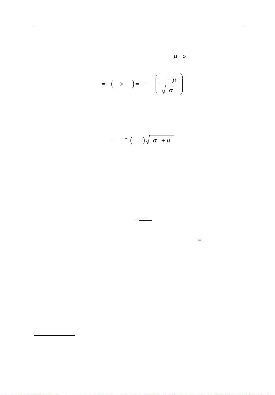
Fronthaul for a Flexible Centralization in C-RANs 69
D ~( )
DD
,
2
PP
dD
,
DP
.
ODD
12
D
D
D
.
09.
QoE (quality of experience) for the users, but is accepted by the operators as it can
reduce the required FH capacity dramatically. As an example, assume the traffic of one
1
BS is approximately Gaussian distributed
with
that the actual data rate D exceeds the deployed capacity D
. Then the probability
can be calculated as:
d
erfc
D
2
(4.5)
2
D
DD
od
1
2
with erfc being the complementary error function. This probability is also known as
the outage probability.
Conversely, we can calculate the capacity that has to be deployed to yield a certain
outage probability as:
erfc
22 (4.6)
As this data rate is identical to percentiles of the corresponding data rate distribution, we write
write D
to identify the data rate that needs to be deployed for an outage probability
99
to easily identify a data rate with its outage probability, that is, we
Po1
of 1%. We also call this data rate the outage rate.
Due to congestion effects, outages can already occur at loads below 100%. To
account for this, the outage rate is usually divided by a safety factor to calculate the
actually deployed data rate D
For example, an outage probability of 1% and a safety factor
[23]:
d
P
1
o
d
(4.7)
imply that the
link will be loaded less than 90% for 99% of the time.
Similar observations, of course, can be made for distributions other than the
Gaussian distribution used here as an example. However, the outage capacity is only
relevant if the data rate follows a varying distribution. Hence, the outage capacity for
the constant data rate of split A is always equal to the maximum data rate.
4.5.3 Statistical Multiplexing onAggregation Links
The statistical multiplexing gain comes into effect in the aggregation network, when
multiple streams with varying data rates are added up. The most straightforward way
1
In fact, the load distribution can never be truly Gaussian, as this would allow for negative loads. However, the
assumption will make the comparison in Section4.5.3 easier.
www.ebook3000.com
Page 81

70 Backhauling/Fronthauling for Future Wireless Systems
DN
NN
DD
.
12
DNN
DD
~( ,)
2
PP
DN
.
DPNN
oD
.
12
PDF
FH data rate in Mbps
to dimension the aggregation link would be simply to scale the data rate for one BS
with the number of BSs being the aggregate, for example, if N BSs are aggregated:
DP
erfc
daggr,nomux do
,
22 (4.8)
However, this neglects the statistical multiplexing. The aggregation of several varying
data streams can be seen as a summation of random variables. From the central limit
theorem [24], it is known that the distribution of the sum of random variables will
converge to a Gaussian distribution. If all data rates follow the same distribution, the
sum will, in fact, be distributed as
daggr
,
. Accordingly, the outage
probability can now be calculated as:
DD
,,
ioaggr oaggr
1
2
erfc
oaggr D
,
2
N
2
D
(4.9)
and the outage rate as:
erfc
daggr
,
22
(4.10)
D
The convergence of probability density functions (PDFs) to a Gaussian distribution is
illustrated in Figure4.5, using split B as an example. The load is uniformly distributed between 0 and 1, which yields a rectangular PDF for a single BS. When adding
multiple varying data streams, the corresponding PDFs are convoluted. This yields a
triangular distribution for two BSs and increasingly Gaussian‐like distributions for
four and eight BSs, as depicted. Figure4.5 additionally illustrates the rationale behind
–3
× 10
2
1 BS
1.5
1
0.5
2 BS
4 BS
8 BS
D
99
D
100
0
0
1000
Figure4.5 PDFs of aggregated FH trafc of one, two, four and eight BSs, and data rate
percentiles
2000 3000 4000 5000
Page 82

Fronthaul for a Flexible Centralization in C-RANs 71
N
g
D
,
22
1
o
()
D
.
Po99 %
09.
No. of supported BS
Deployed FH capacity in Mbps
the outage rates. While the maximum data rate D
the 1% outage rate D
is approximately 3.6 Gbps. Consequently, about 1.4 Gbps of
99
for eight BSs is close to 5 Gbps,
100
aggregation capacity can be saved by accepting a mere 1% of outage probability.
As can be seen from Equation (4.10), the aggregated outage rate scales with
of
the standard deviation, while the outage rate in Equation (4.8) scales with N times the
standard deviation. This difference corresponds to the statistical multiplexing gain.
Practically, this gain occurs because it is very unlikely that a large number of streams
will carry peak traffic at the same time, hence the aggregated probability distribution
is flattened out. The resulting multiplexing gain can be calculated as:
D
1
D
(4.11)
D
N
mux
D
,
daggr,nomux
D
,
daggr
N
with
erfc
P . For a large number of BSs this converges to:
limNg
mux
D
1 (4.12)
Figure4.6 illustrates this multiplexing gain using the data rate distribution from
Section4.5.1. The x‐axis shows the deployed FH data rate D
d,aggr
/ϵ for
and
and the y‐axis the number of BSs that could be supported with a single
aggregation link of corresponding capacity.
3
10
10
10
10
2
1
0
10
1
Split A
Split B
Split C
Split D
w/o mux gain
w/ mux gain
2
10
10
3
10
4
10
5
10
6
Figure4.6 Number of supported BSs versus deployed FH capacity of different functional
split options with and without multiplexing gain (solid and dashed lines, respectively).
Reproduced from [10] with permission from the IEEE
Page 83
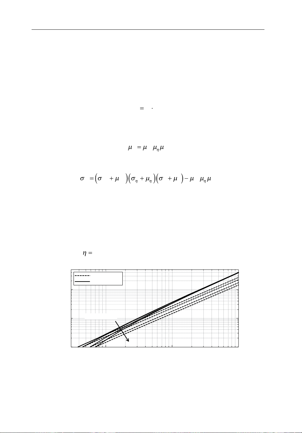
72 Backhauling/Fronthauling for Future Wireless Systems
smR
c
L
,
Ns
.
22
Ns
05.
4
Deployed FH capacity in Mbps
No. of supported BS
For split A there is no aggregation gain because the FH data rate is constant. For the
higher splits, a statistical multiplexing gain of up to a factor of 3 can be observed, with
the gain being more pronounced for a larger number of BSs and for higher‐layer
splits. This can again be explained with probabilistic methods.
Equations (4.1)–(4.4) contain four factors that are varying: N
,η,m and Rc. The
L
modulation scheme and code rate are typically chosen together and are therefore not
independent. We therefore define the spectral efficiency:
Otherwise we can expect that N
,η and s are independent. With this, the mean of
L
(4.13)
the distribution of the product of these variables can be calculated as:
D
(4.14)
and the variance is given by:
222222 22
D
NN ss
LL L
(4.15)
From Equation (4.12) and Equation (4.15) we now see that the total multiplexing
gain depends on the ratio of σ
variances of the parameters N
and μD, which, in turn, depend on the means and
D
, η, m and Rc. In summary, it can be said that the
L
statistical multiplexing gain is larger the more the individual parameters vary. An
illustration for this is given in Figure4.7. It shows the number of supported BSs
versus the deployed FH capacity for split D, but for different load distributions. The
load distributions are uniformly distributed between 0 and 1, 0.2 and 0.8, 0.4 and 0.6,
and constant with
2
10
, respectively. This yields four distributions with the same
w/o mux gain
w/ mux gain
Load variance
1
10
0
10
10
2
10
3
10
Figure4.7 Number of supported BSs versus deployed FH capacity of split option D for
uniform load distributions with different variances
Page 84

Fronthaul for a Flexible Centralization in C-RANs 73
05.
mean load
tively. As can be seen, the multiplexing gain is higher for larger variances, as predicted
by Equation (4.12). In other words, the over‐provisioning of not considering the
multiplexing gain is much worse if the traffic is varying heavily.
but different variances of 0.0833, 0.0300, 0.0033 and 0, respec-
4.6 Convergence ofFronthaul andBackhaul Technologies
The concept of the flexible functional split describes a gradual variation between
what is currently known as FH and BH. Due to the very different requirements of
these two ‘extreme’ versions of a split, they are, in fact, deployed as two different
segments of the network. This means that not only is separate hardware deployed but
also that completely different and largely incompatible standards have evolved. While
this has to be owing to historic development, it is a highly suboptimal solution, as it
not only drives up costs but also makes the management of the network more complex. Even more importantly, the complexity would further increase if the same
approach was followed for a flexible functional split, that is, developing different
hardware and standards for each of the split options. Instead, it is highly desirable to
converge the technologies of the current two options and design a unified transport
network. This unified transport network should not only be able to support any
number of different functional splits but should also be agnostic with respect to the
underlying access technology to make it future proof for the coming generations of
mobile networks. In the following, an overview of the existing solutions across different layers is given and convergence to a unified technology is discussed.
4.6.1 Physical Layer Technologies
PHY‐layer technologies pose an upper bound on the performance that can be achieved
in FH networks. Additionally, they have a large impact on the cost of the FH links, as
specific hardware is required for each technology. In general, PHY‐layer technologies
can be grouped into wired and wireless technologies. The wired technologies can be
further divided into fibre/optical technologies and copper/electrical technologies,
while wireless technologies are usually distinguished by the carrier frequency they
utilize.
The most intuitive – and hence most widely used – option in current C‐RAN
deployments is fibre. It offers very large capacities of tens of Gbps, low latency and
high reliability. The range is only limited by the tolerable latency and the cost of
repeaters. Dedicated point‐to‐point links have been used so far for FH in fully
centralized C‐RAN, meaning that one fibre core or one wavelength channel is
dedicated to an FH link from RRH to BBU. In order to exploit statistical multiplexing
and to avoid a heavy underutilization of the fibre in a flexible C‐RAN deployment,
time‐shared optical networks could be used [25] in the future. The main disadvantage
Page 85

74 Backhauling/Fronthauling for Future Wireless Systems
of fibre technology is that it is expensive and slow to deploy due to the extensive civil
works required. Adding right‐of‐way issues to that prohibits fibre connectivity
toevery BS, especially in the case of dense deployments of small cells. While
some operators have their own fibre networks, others– especially non‐incumbent
operators – have to rely on expensive third‐party leases, further complicating the
business case.
In the context of classical BH, that is, very high‐layer splits, a number of other
PHY technologies are in use, making them principal candidates for a flexible C‐RAN
solution. Copper‐based solutions like coax cables face the same economic problems
as fibre but in addition offer less capacity. In some cases, existing deployments can be
utilized to mitigate that effect. For example, digital subscriber line (DSL) connection
of shop owners could be used to provide FH for indoor BSs if a corresponding incentive was offered. However, due to the limited capacity and protocol overhead of DSL
technology, even with new technology generations such as G.fast [26], this is only an
option for higher‐layer splits.
Wireless options, in general, offer the benefit that they are cheaper and faster to
deploy, as only comparatively little civil work is required. On the other hand, their
range and reliability are limited by the much higher path loss.
One category of wireless transport solutions uses similar carrier frequencies to
the access links, that is, sub‐6 GHz bands. These are more suitable for high‐layer
splits, as their respective capacities are comparable with the access link technology. The latency can also be quite high because similar protocols to the access
link have to be observed. While some of these technologies can, in principle, use
the same hardware as the access link and therefore benefit from economies of
scale, additional licensed frequency bands have to be acquired or already available
ones have to be assigned, which again makes the overall deployment quite expensive. On the other hand, sub‐6 GHz technologies offer point‐to‐multipoint connections, which can significantly reduce the number of required antennas and thus
reduce CAPEX.
Microwave technology up to a few tens of GHz is already widely used in classical
BH and could also be an option for lower‐layer splits. With capacities of currently up
to 1 Gbps and a range of a few tens of kilometres, it can be utilized for the ‘last mile’,
although not for the aggregation network. The main disadvantage is that, again,
licensed frequency bands are utilized, which increases cost and deployment time.
Also, the limited range requires the set‐up of potentially multiple solid masts for the
intermediate antenna dishes along the transmission path. This results in the need for
real estate or roof access, all of which comes with administrative and cost‐related
overhead.
Millimetre‐wave technology, also sometimes referred to as V‐band or E‐band
technology depending on the corresponding frequency bands between 60 and
90 GHz, is another good option for wireless FH. While still a relatively new technology, it already offers a capacity of up to 10 Gbps and per‐hop latencies as low as
Page 86

Fronthaul for a Flexible Centralization in C-RANs 75
10 ns. In addition, it utilizes unlicensed or lightly licensed bands, which is advantageous in terms of cost and deployment time. However, mmWave frequencies suffer
from relatively high free‐space path loss. Although this can be partially compensated
with high‐gain antennas, it still limits the total range to a few kilometres at most for
E‐band and a few hundred metres for V‐band. With current research into large‐scale
antenna arrays with hundreds of individual antenna elements, beamforming techniques could be used to enable a flexible selection of point‐to‐point links. Thereby,
time sharing or quick reconfiguration of interconnections in cases of large changes
in traffic distribution could be enabled. Due to the low wavelength at mmWave
frequencies (5 mm at 60 GHz), the corresponding antenna arrays can be built
relatively small.
Finally, free space optics (FSO) is a wireless technology that utilizes laser light for
communication. While it offers similar capacities and latencies to mmWave technology, it is susceptible to misalignment and wind sway due to its narrow beam width.
Weather effects like fog or snow can also limit the range or decrease the reliability.
Still, it is a viable option for the last mile in scenarios where these effects can be
neglected.
In summary, a more flexible approach to the functional split can benefit from a
more heterogeneous selection of FH technologies. Lower cost and higher deployment
speed make wireless technologies attractive on the last mile and the first level of
aggregation. Range limitation can be overcome by multi‐hop chains at the cost of
increased latency. Still, it is undisputed that the higher levels of the aggregation network have to be composed of fibre, which alone offers the capacity to aggregate
hundreds of BSs.
To further illustrate the suitability of the discussed technologies for the different
functional splits, Figure4.8 shows the requirements of the four splits A–D in terms of
latency and capacity (for a single BS) versus the different technologies, based on a
market study in [27]. As can be seen, the utilization of split B or C would already
enable a more heterogeneous selection of applicable PHY technologies. It should be
noted that all discussed FH technologies can be expected to advance in the future;
however, access link technology will similarly progress, so that the mapping can still
be considered viable for future networks.
4.6.2 Data/MAC Layer Technologies
On the MAC layer, there currently exist two completely different standards
corresponding to the two different extremes of the functional split: full centralization
and full decentralization. In fully centralized C‐RAN architectures, CPRI has evolved
as the de facto industry standard for digital FH, while the classical BH in decentralized
networks utilizes Ethernet. In terms of the data plane protocol, the incompatibility of
these two standards arises mainly from the different frame formats that are used and
Page 87

76 Backhauling/Fronthauling for Future Wireless Systems
Data rate in Mbps
Latency (round trip time per hop) in s
10
1
10
10
10
10
–4
–3
–2
–1
10
0
5
Split A
Split B
Split C
Split D
4
10
Fibre(CWDM/dark)
mmWave
μ-Wave (PtP/PtMP)
FSO
3
10
Metro optical
2
10
Passive optical network (PON)
Sub-6 GHz
10
xDSL
Figure4.8 Functional split requirements versus physical layer technologies. Reproduced
from [10] with permission from the IEEE
the strict requirements on timing and jitter that were introduced for CPRI. This incompatibility has resulted in the fact that two separate transport networks have to be
deployed, which is a suboptimal solution as it increases deployment cost and
management overhead.
At first glance, the introduction of a flexible split seems to further complicate
this issue, as neither of the two existing standards will be compatible with all
intermediate splits. However, this offers the chance to design a unified transport
technology that is not only compatible with the existing two standards, but with a
wide range of functional splits. Such a unified technology does not need to be
designed from scratch but could be based on one of the existing standards.
Investigations are already under way to enable CPRI over Ethernet [28], while also
taking the possibility into account of mapping arbitrary data to Ethernet frames.
The main challenge in such a unified frame format is to meet the strict requirements of the lower splits in terms of latency and jitter. To achieve them, large
improvements in time synchronization as well as a reduction in deterministic delays
will have to be achieved. GPS‐assisted synchronization or synchronous Ethernet
using the precision time protocol [29] are available and could be utilized for this.
In terms of capacity, 10 Gbps Ethernet is already standardized (802.3.ae, ak, an
[30]) and study groups are investigating data rates up to 400 Gbps [31]. On the
other hand, a recent initiative aims to standardize a more flexible FH in the form of
the next generation fronthaul interface (NGFI) [20]. However, while its goal is to
make the FH more flexible and support higher‐layer splits, it is currently not considering utilizing it for BH as well.
Page 88

Fronthaul for a Flexible Centralization in C-RANs 77
4.6.3 Network Layer Technologies
The network layer is responsible for switching and routing traffic between network
nodes. As such, it has a decisive impact on a converged transport network
architecture. While BH networks inherently work with packet switching, FH
networks commonly use dedicated point‐to‐point connections. A converged transport network will have to support packet switching and point‐to‐multipoint connections, as this simplifies implementation and management and allows for arbitrary
placement of the centralized processing elements, as discussed in Section 4.7.
Currently, they can be located only at sites with sufficient dedicated links to support
the RRHs, leading to a concentration in a low number of large data centres. However,
to enable the fast migration of RAN functionality from one data centre to another,
and to adapt to varying load profiles across BSs, packet switching is the only efficient option.
One challenge for this is that additional delays are introduced due to the
processing time of switches and routers. Especially for very large networks with
many hops, this could make low‐layer functional splits infeasible. However, recent
advances in low‐latency switching have decreased the switching delay to about
100 ns, which is three orders of magnitude lower than the requirements for a fully
centralized network.
A more important impact comes from queueing, as this not only introduces
additional delay but it is also indeterminate as the length of the queue will vary with
the variation in packet arrival. Prioritization of packets can be used to reduce the total
wait time for certain packets. This is managed via quality of service (QoS) class
identifiers; however, the means of choice for providing fairness among QoS classes
are probabilistic scheduling methods, adding another layer of unpredictability. For a
converged transport network architecture, new methods would have to be found to
make the delay more predictable and guarantee maximum latencies. Special QoS
classes for RAN functionalities could be introduced that prioritize corresponding
packets above everything else. For times of congestion, the dropping of other packets
could be considered. The requirements for higher‐layer applications are, in fact, many
orders of magnitude larger than RAN packages, for example, Voice‐over‐IP requires
latencies of tens of ms as compared to the hundreds of µs required for a fully centralized RAN architecture. Hence, RAN requirements instead of application‐layer
requirements will dominate the design of a converged BH/FH network. On the other
hand, the application layer could also benefit from greatly reduced latencies, enabling
‘tactile Internet’ applications [32] like virtual reality, automation control or remote
vehicle steering. Still, this would require an update of the whole BH network. While
the queueing policy can usually be modified via software or firmware updates, low‐
latency switches require new hardware at substantial cost. Also, switches need to
enable network synchronization as discussed in the section above, which is not widely
supported by the currently deployed hardware.
Page 89

78 Backhauling/Fronthauling for Future Wireless Systems
4.6.4 Control andManagement Plane
One common requirement from the sections above is that future networks need to be
more flexible. The introduction of more heterogeneous PHY technologies, a unified
frame format able to carry traffic from different splits and packet‐switched FH all
support a transport network that can be adapted to follow, for example, hourly or daily
traffic variations. Still, the evolution to 5G networks will bring along a further process
of updating existing deployments or adding more hardware or functionalities. In
particular, with the advent of mmWave access technology, massive MIMO and the
tactile Internet, the requirements on the transport network will change and potentially
become even more demanding. In order to adapt the network both in the short and in
the long term, a universal management plane is required. This management plane will
be in charge of policies ranging from connection control on the RAN and FH links
over congestion control and load balancing to routing and QoS policies.
The centralization of RAN functionality also poses new challenges in terms of
reliability, as the data centres hosting such functionalities are potential single points
of failure, for example in the case of localized power outage or malicious attacks from
hackers. As such, the control and management plane also has to be in charge of outage
protection and failover control. This will include functionalities ranging from rerouting traffic in the case of a single link outage to migrating complete centralized RAN
functionality from one data centre to another in the case of more severe malfunctions.
In order to provide low failover times, 1 + 1 protection schemes could be used on the
transport network at the cost of additional deployed capacities.
For the implementation of such a universal control and management plane, software‐defined networking (SDN) [33] and network function virtualization (NFV) [34]
are good candidate technologies as they provide–among other things–unification
via abstraction layers. The main challenge arises from the scale to handle a complete
mobile network, including BSs, the transport networks, centralized RAN functionality and a possibly virtualized network core.
4.7 Enablers ofaFlexible Functional Split
The utilization of a flexible functional split impacts not only the FH network but
needs to be supported by the BSs and the central processing entity. The increased
flexibility that is offered by a larger number of split options comes at the price of
higher hardware complexity at the respective endpoints. In this section, a short
overview is given of the technologies that are needed from the baseband processing
perspective to enable a flexible functional split.
As the functional split determines the type of joint processing that can be performed,
the split has to be adapted to the current scenario. For example, in a dense deployment
with a large number of cell‐edge users, CoMP techniques requiring a lower‐layer split
might yield large gains in user throughput. On the other hand, macro‐cell deployments
Page 90

Fronthaul for a Flexible Centralization in C-RANs 79
might not benefit from a high degree of centralization and therefore a higher‐layer
split could be employed, reducing the load on the aggregation network. This means
that the functional split will have to be adapted in space and also in time to fit the
scenario. This not only requires more flexible interfaces on the transport network, as
discussed in the previous section, but also that the hardware both in the BS and in the
central entity can perform the respective processing. This brings two problems: first,
in order to support higher‐layer splits, BSs would need to be equipped with the same
hardware as fully decentralized BSs. As one of the intended advantages of a centralized RAN is smaller BSs, this effect would be nullified. Second, baseband processing
is usually implemented on dedicated hardware like FPGAs or ASICs, which cannot be
flexibly reconfigured to match any functional split. As a consequence, a more flexible
hardware architecture is required in addition to the converged transport network.
Recent progress in the IT industry provides very promising solutions for this with the
approach of RAN virtualization and ‘cloudification’.
Although the term ‘cloud’ was part of even the first considerations on C‐RAN [1],
the first deployments did not follow the principles of cloud computing as they are
known in the IT industry, namely providing a ‘shared pool of configurable computing
resources that can be rapidly provisioned’ [35]. Instead, the first deployments followed
the approach of simply splitting up the conventional base stations by separating the
baseband hardware from the RF front‐ends [36]. However, this simple hardware
centralization does not embrace the concept of cloud computing. Many advantages of
centralized processing, like load balancing and energy savings, are only possible if
the baseband hardware can be dynamically allocated and configured according to
demand. This requires a virtualization of the available hardware, which, in general,
requires the utilization of GPPs. Only if the hardware can be quickly and easily reconfigured to perform smaller or larger parts of the baseband processing can a flexible
functional split efficiently be employed. The main challenge with this is that the
implementation of baseband processing requires far higher throughput and lower
latencies than traditional IT applications, which is why dedicated hardware is used in
conventional BBUs. Additionally, the virtualization of the hardware introduces extra
overhead in the form of a so‐called hypervisor that oversees and controls the
provisioning and operation of the virtual machines.
In order to reduce the overhead of virtualization, newer approaches to virtualized
hardware employ so‐called ‘bare metal’ servers. These do not require an additional
operating system for each virtual machine. Instead, the hypervisor can directly
communicate with the physical hardware. This also has the advantage that the physical
hardware can be fully dedicated to a certain task, for example, a physical processor
core can be assigned to the processing of a specific BS. This makes it far easier to
guarantee performance when compared to a conventional virtualized system, where a
physical core might have to process several virtual machines. Some recent works
show that it is possible to implement computationally complex processing like turbo
decoding on general‐purpose hardware in real time [37]. Additionally, the amount of
Page 91

80 Backhauling/Fronthauling for Future Wireless Systems
required processor cores can be predicted, allowing for precise provisioning in order
to avoid outage by under‐provisioning or wasting resources by over‐provisioning
[38]. However, the jury is still out as to whether the implementation of the full baseband stack on GPP is cost‐ and energy‐efficient.
As an alternative, certain parts of the baseband processing could be outsourced to
dedicated hardware accelerators while maintaining the virtualization approach. The
newest generation of servers can not only be equipped with GPPs but can also be
supplemented with DSP cores [39]. The operation of fast Fourier transformation
(FFT) and inverse FFT (IFFT) and channel coding/decoding, in particular, can be
much more efficiently performed by dedicated hardware. Field trials have already
shown the validity of such a hardware‐accelerator‐assisted GPP implementation
[40]. While these approaches are mainly designed for the central processing entity, a
similar architecture can be employed on the BS side. The deployment of micro‐
servers or ‘cloudlets’ at BSs has already been envisioned, albeit mainly for the
purpose of application processing [41]. However, this perfectly complements the
approach of the flexible split. GPP cloudlets with additional hardware accelerators
could be deployed and used for baseband processing when a higher‐layer split is
configured, and when a lower‐layer split is configured, the now idle hardware could
be utilized for user‐application processing, thereby avoiding underutilization of the
hardware at the BSs.
In summary, the flexibility offered by a virtualized cloud‐RAN implementation
will also be the basis for the flexible functional split that can be dynamically adapted
in time and space to optimally reflect the scenario in terms of traffic density, fronthaul
load and hardware utilization.
4.8 Summary
Taking all of the above into account, it becomes clear that the design of the FH network will be a major challenge in future networks. While the approach of C‐RAN
offers tremendous advantages, the FH could become a major bottleneck, both in terms
of performance and cost efficiency. A more flexible functional split will help to mitigate this problem. A partial centralization can reduce the requirements on the FH
dramatically in scenarios where full centralization offers no advantage. In particular,
the data rate can be easily lowered and– more importantly – coupled to the actual
user traffic. Network operators, therefore, need to carefully decide whether the traffic
demand justifies the expensive FH for high centralization and how much gain can be
expected from joint processing. In the aggregation network, the multiplexing gain
plays an additional important role. As it makes use of the temporal and special traffic
variation within a network, it is beneficial to aggregate traffic with a highly variable
distribution. As described in Section4.5, the variance mainly results from variable BS
load and a variable SINR. Therefore, base stations exhibiting different load patterns
Page 92
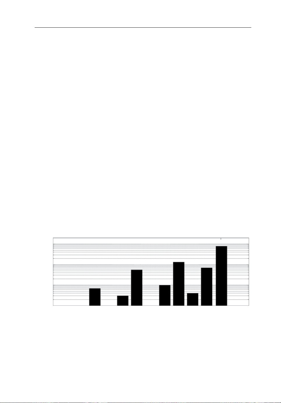
Fronthaul for a Flexible Centralization in C-RANs 81
Split A
Split B Split C Split D
No. of supported BS
should be aggregated, for example rural areas and inner cities, and similarly those
with different SNR distributions, for example macro cells and dense small cells. The
effect will be even more pronounced in a converged BH/FH network. By adding
further traffic in the form of BH and control signalling, the traffic becomes more
diverse, thereby increasing the benefit of statistical multiplexing.
The main benefit of the reduced FH requirements will come in the form of reduced
deployment costs. Less FH capacity per BS means that less capacity needs to be
deployed. To summarize the effect of statistical multiplexing and the general data rate
reduction of higher‐layer splits on the deployment cost, Figure 4.9 illustrates the
number of BSs that can be supported by a single link using exemplary FH technologies. While, for example, a separate fibre core with 20 Gbps capacity is required for
every seven BSs in a fully centralized network corresponding to split A, more than
800 can be supported per fibre core when utilizing split D. Similarly, more heterogeneous technologies like wireless FH can only be utilized with higher‐layer splits,
thereby replacing the expensive fibre entirely on the last mile.
Starting from the physical layer technologies, future mobile networks have to aim
to converge the BH and FH technologies and utilize unified methods across all network layers. They have to transport different types of traffic, meet a set of greatly
different QoS parameters and be flexibly reconfigurable while utilizing different
physical technologies. While the implementation of such a network will be challenging in the beginning, it offers the chance to reduce the complexity of network
management and operation substantially while additionally reducing deployment
cost, culminating in a virtualization of the transport network. In fact, a fully virtualized RAN should not only aim to virtualize a single part of the network like baseband
processing, but all elements including base stations, fronthaul, baseband processors
10
10
10
10
3
2
1
00 00
0
xDSL
7
Fibre
μ-Wave
xDSL
55
3
Fibre
μ-Wave
xDSL
10
134
4
Fibre
μ-Wave
xDSL
811
71
Fibre
μ-Wave
Figure4.9 Number of supported BSs for different aggregation technologies: xDSL at
200 Mbps; μ‐wave at 2 Gbps; bre at 20 Gbps. Reproduced from [10] with permission
from the IEEE
Page 93

82 Backhauling/Fronthauling for Future Wireless Systems
and backhaul. Numerous tools such as a flexible functional split, a converged BH/FH
network, SDN, NFV and cloudlets will have to come together to achieve the flexibility that is required to improve performance, cost efficiency and adaptability of
future mobile networks.
Acknowledgement
The research leading to these results has received funding from
the European Union’s Horizon 2020 research and innovation
programme under grant agreement No 671551 and the European
Union’s Seventh Framework Programme (FP7/2007‐2013)
under grant agreement No 317941. The European Union and its
agencies are not liable or otherwise responsible for the contents of this document; its
content reflects the view of its authors only.
References
[1] Guan, H., Kolding, T. and Merz, P. (2010) Discovery of cloud‐RAN.
[2] Irmer, R., Droste, H., Marsch, P., Grieger, M., Fettweis, G., Brueck, S., Mayer, H.‐P., Thiel, L. and
Jungnickel, V. (2011) Coordinated multipoint: Concepts, performance, and field trial results. IEEE
Communications Magazine, 49(2), 102–111.
[3] Sawahashi, M., Kishiyama, Y., Morimoto, A., Nishikawa, D. and Tanno, M. (2010) Coordinated
multipoint transmission/reception techniques for LTE‐advanced. IEEE Wireless Communications,
17(3), 26–34.
[4] Caire, G. and Müller, R. (2001) The Optimal Received Power Distribution of IC‐Based Iterative
Multiuser Joint Decoders. Proceedings of the 39th Annual Allerton Conference on Communication,
Control and Computing, Monticello, IL, October.
[5] Rost, P., Bernardos, C. J., De Domenico, A., Di Girolamo, M., Lalam, M., Maeder, A., Sabella, D.
and Wübben, D. (2014) Cloud Technologies for Flexible 5G Radio Access Networks. IEEE
Communications Magazine, 52(5), 68–76.
[6] Armbrust, M., Fox, A., Griffith, R., Joseph, A. D., Katz, R., Konwinski, A., Lee, G., Patterson, D.,
Rabkin, A., Stoica, I. and Zaharia, M. (2010) A view of cloud computing. Communications ACM,
53(4), 58.
[7] Guo, B., Cao, W., Tao, A. and Samardzija, D. (2013) LTE/LTE‐A Signal Compression on the CPRI
Interface. Bell Labs Technical Journal, 18(2), 117–133.
[8] Suryaprakash, V., Rost, P. and Fettweis, G. (2015) Are Heterogeneous Cloud‐Based Radio Access
Networks Cost Effective? IEEE Journal on Selected Areas in Communication, 33(10), 2239–2251.
[9] Wübben, D., Rost, P., Bartelt, J., Lalam, M., Savin, V., Gorgoglione, M., Dekorsy, M. and Fettweis,
G. (2014) Benefits and Impact of Cloud Computing on 5G Signal Processing: Flexible centralization through cloud‐RAN. IEEE Signal Processing Magazine, 31(6), 35–44.
[10] Bartelt, J., Rost, P., Wübben, D., Lessmann, J., Melis, B. and Fettweis, G. (2015) Fronthaul and
Backhaul Requirements of Flexibly Centralized Radio Access Networks. IEEE Wireless
Communications, 22(5), 105–111.
[11] Common Public Radio Interface, CPRI Specification V6.0, 2013. Available at: http://www.cpri.
info/. Accessed: September 1, 2015.
Page 94

Fronthaul for a Flexible Centralization in C-RANs 83
[12] Nadiv, R. and Naveh, T. (2010) Wireless Backhaul Topologies: Analyzing Backhaul Topology
Strategies. Ceragon white paper, August. Available at: https://www.ceragon.com/images/
Reasource_Center/White_Papers/Ceragon_Wireless_Backhaul_Topologies_Tree_vs_%20Ring_
White_Paper.pdf. Accessed: October 8, 2015.
[13] 3GPP (2015) 3GPP TS 36.213, ‘Evolved Universal Terrestrial Radio Access (E‐UTRA); Physical
layer procedures (Release 12),’ v12.5.0, April.
[14] Valenti, M. C. (1999) Iterative Detection and Decoding for Wireless Communications. PhD disser-
tation, Virginia Polytechnic Institute and State University, Blacksburg, VA.
[15] Paul, H., Shin, B.‐S., Wübben, D. and Dekorsy, A. (2013) In‐network‐processing for small cell
cooperation in dense networks. Proceedings of the IEEE 78th Vehicular Technology Conference,
Las Vegas, NV, September.
[16] Fritzsche, R., Rost, P. and Fettweis, G. (2015) Robust Rate Adaptation and Proportional Fair
Scheduling With Imperfect CSI. IEEE Transactions on Wireless Communication, 14(8),
4417–4427.
[17] De Domenico, A., Savin, V. and Ktenas, D. (2013) A backhaul‐aware cell selection algorithm for
heterogeneous cellular networks. IEEE 24th International Symposium on Personal Indoor and
Mobile Radio Communications, London, September.
[18] Larsson, E., Edfors, O., Tufvesson, F. and Marzetta, T. (2014) Massive MIMO for next generation
wireless systems. IEEE Communications Magazine, 52(2), 186–195.
[19] Dötsch, U., Doll, M., Mayer, H. P., Schaich, F., Segel, J. and Sehier, P. (2013) Quantitative Analysis
of Split Base Station Processing and Determination of Advantageous Architectures for LTE. Bell
Labs Technical Journal, 18(1), 105–128.
[20] Huang, J., Yuan, Y. etal. (2015) White Paper of Next Generation Fronthaul Interface. White paper,
June. Available at: http://labs.chinamobile.com/cran/wp‐content/uploads/White%20Paper%20of%20
Next%20Generation%20Fronthaul%20Interface.PDF. Accessed: October 8, 2015.
[21] Khalili, S. and Simeone, O. (2015) Uplink HARQ for C‐RAN via Low‐Latency Local Feedback
over MIMO Finite‐Blocklength Links. arXiv preprint, arXiv:1508.06570.
[22] Rappaport, T. S. (2002) Wireless Communications: Principles and Practice, 2nd edition.
NewJersey: Prentice Hall.
[23] d’Halluin, Y., Forsyth, P. A. and Vetzal. K. R. (2007) Wireless Network Capacity Management:
AReal Options Approach. European Journal of Operations Research, 176(1), 584–609.
[24] Rice, J. (2006) Mathematical Statistics and Data Analysis, 2nd edition, Belmont: Duxbury Press,
pp. 181–187.
[25] Zervas, G., Triay, J., Amaya, N., Qin, Y., Cervelló‐Pastor, C. and Simeonidou, D. (2011) Time
Shared Optical Network (TSON): a novel metro architecture for flexible multi‐granular services.
Optics Express, 19(26), B509–B514.
[26] ITU‐T Recommendation G.9701, ‘Fast access to subscriber terminals (G.fast) – Physical layer
specification,’ 2014.
[27] NFSO‐ICT‐317941 iJOIN, ‘D5.2– Final Definition of Requirements and Scenarios,’ November
2014. Available at: http://www.ict‐ijoin.eu/wp‐content/uploads/2012/10/D5.2.pdf. Accessed:
September 1, 2015.
[28] IEEE (2014) ‘Standard for Radio over Ethernet Encapsulations and Mappings.’ IEEE Standard
P1904.3, 2014. Available at: http://standards.ieee.org/develop/project/1904.3.html. Accessed:
September 1, 2015.
[29] IEEE (2013) ‘Standard for a Precision Clock Synchronization Protocol for Networked Measurement
and Control Systems.’ IEEE Standard P1588‐2008, 2013. Available at: https://standards.ieee.org/
develop/project/1588.html. Accessed: September 1, 2015.
[30] IEEE (2014) ‘Standard for Ethernet.’ IEEE Standard P802.3‐2012, 2014. Available at: http://standards.
ieee.org/findstds/standard/802.3‐2012.html. Accessed: September 1, 2015.
Page 95

84 Backhauling/Fronthauling for Future Wireless Systems
[31] IEEE(2014) ‘Standard for Ethernet Amendment: Media Access Control Parameters, Physical
Layers and Management Parameters for 400 Gb/s Operation.’ IEEE Standard P802.3bs, 2014.
Available at: http://www.ieee802.org/3/bs/index.html. Accessed: September 1, 2015.
[32] Fettweis, G. (2014) The Tactile Internet: Applications and Challenges. IEEE Vehicular Technology
Magazine, 9(1), 64–70.
[33] Open Networking Foundation (2012) Software‐Defined Networking: The New Norm for Networks.
White Paper, April. Available at: https://www.opennetworking.org/images/stories/downloads/
white‐papers/wp‐sdn‐newnorm.pdf. Accessed: September 1, 2015.
[34] ETSI Industry Specification Group for Network Functions Virtualisation (n.d.). Available at: http://
www.etsi.org/technologies‐clusters/technologies/nfv. Accessed: September 1, 2015.
[35] Mell, P. and Grance, T. (2011) The NIST Definition of Cloud Computing. US National Institute of
Science and Technology. Available at: http://csrc.nist.gov/publications/nistpubs/800‐145/
SP800‐145.pdf. Accessed: September 1, 2015.
[36] Li, L., Liu, J., Xion, K. and Butovitsch, P. (2012) Field test of uplink CoMP joint processing with
C‐RAN testbed. 7th International ICST Conference on Communication and Networking China,
August.
[37] Paul, H., Wübben, D. and Rost, P. (2015) Implementation and Analysis of Forward Error Correction
Decoding for Cloud‐RAN Systems. 2nd International Workshop on Cloud‐Process. Heterogeneous
Mobile Communication Networks, London, UK, June.
[38] Rost, P., Talarico, S. and Valenti, M. C. (2015) The Complexity‐Rate Tradeoff of Centralized Radio
Access Networks. arXiv preprint, arXiv:1503.08585.
[39] Hewlett‐Packard Company (2014) Efficient deployment of virtual network functions on HP
ProLiant m800. Technical white paper. Available at: http://h20195.www2.hp.com/V2/getpdf.
aspx/4AA5‐5395ENW.pdf. Accessed: September 1, 2015.
[40] Huang, C. I. J., Duan, R., Cui, C., Jiang, J. X. and Li, L. (2014) Recent Progress on C‐RAN
Centralization and Cloudification. IEEE Access, 2, 1030–1039.
[41] Satyanarayanan, M., Bahl, P., Caceres, R. and Davies, N. (2009) The case for VM‐based cloudlets
in mobile computing. IEEE Pervasive Computing, 8(4), 14–23.
Page 96

5
Analysis andOptimization
forHeterogeneous Backhaul
Technologies
Gongzheng Zhang,1 Tony Q. S. Quek,2 Marios Kountouris,3 Aiping Huang1
and Hangguan Shan
1
College of Information Science and Electronic Engineering, Zhejiang University,
China
2
Information Systems Technology and Design Pillar, Singapore University of
Technology and Design, Singapore
3
Mathematical and Algorithmic Sciences Laboratory, France Research Centre,
Huawei Technologies, France
1
5.1 Introduction
Densifying the cellular network via deploying ultra‐dense small‐cell base stations
(BSs) is a promising way to meet the tremendous demand for cellular data as we
approach next generation cellular networks [1, 2]. To carry the traffic from BSs to the
core network and vice versa, the backhaul network needs to be enhanced proportionally. Meanwhile, low delay on the radio access and backhaul links becomes essential
to deliver a wide range of services and applications in future cellular networks, for
example, VoIP and online gaming with an acceptable quality of service (QoS) [3]. As
a result, backhaul has become the next big challenge for providing reliable and timely
connectivity between BSs and the core network [4, 5], especially for delay‐sensitive
services or network functionalities.
Backhauling/Fronthauling for Future Wireless Systems, First Edition.
Edited by Kazi Mohammed Saidul Huq and Jonathan Rodriguez.
© 2017 John Wiley & Sons, Ltd. Published 2017 by John Wiley & Sons, Ltd.
Page 97

86 Backhauling/Fronthauling for Future Wireless Systems
Unlike traditional macro‐cell BSs, which are usually directly connected to the
operator’s core network through fibre with very low latency or microwave links with
high reliability, small‐cell BSs are not always in easy‐to‐reach locations, for example
near street level or lampposts rather than rooftops, which makes conventional fibre or
microwave links impractical or cost‐inefficient. Many wired and wireless technologies
have been proposed as backhaul solutions for small cells [6–10]. Wired backhaul technologies have the advantages of high reliability, high data rates and high availability.
However, they may sustain long and variable delays in the backbone routes or switches
due to multiple hops, especially for xDSL, which can only reach up to 200–400 metres
per single hop [11]. Wireless backhaul can be deployed more easily and at lower cost.
Sub‐6 GHz wireless backhaul has the advantage of non‐line‐of‐sight (NLOS) transmission, while the presence of interference due to the co‐existence issue makes
the wireless links unreliable and introduces unpredictable delay. Millimetre‐wave
(mmWave) technologies of 60 GHz and 70–80 GHz are another potential backhaul
solution, as they offer high capacity and reliability based on line‐of‐sight (LOS) links.
Due tothe small carrier wavelength and possibility of directional beamforming, the
mmWave links can indeed be modelled as pseudo‐wired without interference, which
makes them extremely suitable for dense small‐cell networks [12]. However, multi‐
hop implementation is needed in the absence of LOS, which causes additional delay.
Due to these diverse characteristics, heterogeneous backhaul deployment willbe a
potential solution. It is essential to model and compare the performance ofthese different types of backhaul technologies to provide guidelines for such a system design.
Besides their capabilities, the cost of these backhaul technologies behaves differently in terms of both deployment and operation, which is another aspect that may
limit the deployment of small‐cell networks. Specifically, the deployment of a wired
link (e.g. fibre or cable) is much more expensive than a wireless link, while the operational cost (e.g. the power consumption) of a wired link is much lower than a wireless
link. As a result, it is quite a challenging task to identify the most appropriate and
efficient solution for backhaul infrastructure, especially for dense small‐cell networks.
Furthermore, optimizing the configurations so as to minimize the cost is critical for
the operators.
Furthermore, in a two‐tier heterogeneous cellular network where a small‐cell network is overlaid with a macro‐cell network, BS association is another challenging
problem. From a signal quality perspective, users will prefer to associate with macro‐
cell BSs due to their larger transmit power. By contrast, from a load point of view,
users will prefer to associate with small‐cell BSs, which are usually underutilized.
Furthermore, imperfections in the backhaul link may result in packet delay increases
if users associate with small‐cell BSs. Therefore, the BS association policy should
take the signal quality, load and backhaul into consideration to optimize the overall
network performance.
As a timely and practically relevant topic, backhaul has been drawing much attention
in recent years from many angles, including transmission, cost and system design. Various
Page 98

Analysis andOptimization forHeterogeneous Backhaul Technologies 87
backhaul technologies are introduced in [4–10]. Modelling the delay perfor mance of
wired networks through measurements has a long history, and the results for routers
and switches can be found in [13–17]. The transmission characteristics of mmWave
andsub‐6 GHz form another hot topic, and initial results for mmWave can befound in
[12, 18–21]. There is some system design work taking backhaul into consideration, where
the backhaul is considered as a capacity constraint [22, 23]. Some other work tries
to estimate the backhaul cost via listing all the components of the network and their
prices,which is practical but lacks theoretical analysis [24–27]. Cost models for some
specifictechnologies are presented in [28–30]. The BS association problem is studied
for heterogeneous cellular networks in [31–33]. Different joint spectrum-partitioning and
bias-based BS association algorithms are proposed to maximize the user rate or rate
coverage in [34–36]. However, backhaul is not considered in thatwork, even though it has
a significant effect, as shown in our work, and can change the whole picture. As mentioned previously, a general backhaul model is needed, especially for studying the delay
performance and designing the backhaul network to minimize cost.
The main contributions of this work are twofold. First, we propose a backhaul
model for four promising backhaul technologies as a means to investigate the effect
of different backhaul technologies on the network performance. Specifically:
• The packet delay in backhaul links is modelled for four technologies, includ-
ing fibre, xDSL, mmWave and sub‐6 GHz, each with distinct transmission
characteristics.
• The mean packet delay and delay‐limited success probability are analysed and
compared for the above‐mentioned technologies. Our results show that fibre is
always the best choice, sub‐6 GHz and xDSL are suitable for links with modest link
length, while mmWave is a very competitive candidate for short links in terms of
delay performance.
• A tractable model for quantifying the backhaul cost is presented and the mean
backhaul cost per small‐cell BS is analysed. A key result is that there exists an
optimal gateway density which minimizes the mean cost, and the optimal operating
point depends on the ratio of per gateway cost to per unit length link cost.
The second contribution of our work is to propose a backhaul‐aware BS association
policy for two‐tier cellular networks. The aim is to minimize the mean network packet
delay coming from both the backhaul and radio access links. Some remarkable conclusions are obtained from numerical results. Specifically:
• Backhaul delay may dominate the mean network packet delay from gateways to
users when the backhaul network does not scale proportionally to the increasing
number of small cells.
• The proposed backhaul‐aware BS association policy outperforms conventional
association policies with or without biasing, in terms of mean network packet delay.
Page 99
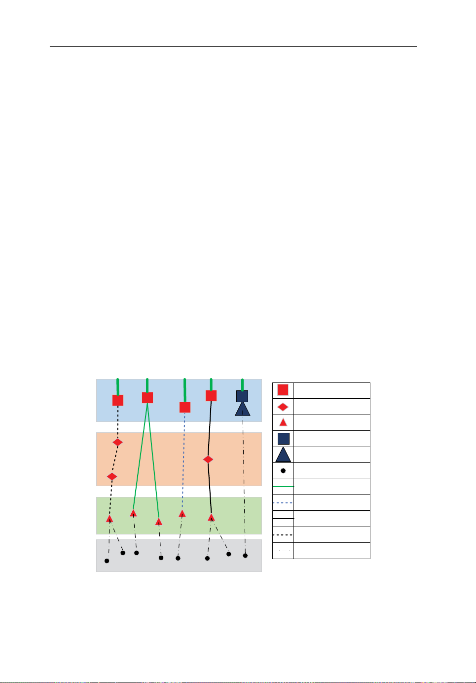
88 Backhauling/Fronthauling for Future Wireless Systems
• BS association without biasing may even outperform biased ones without consid-
ering backhaul, which implies that users may be misled into associating with small‐
cell BSs, thus deteriorating the system performance.
The remainder of this chapter is organized as follows. Section5.2 presents the
network model, the packet delay model and the cost model. The mean packet delay
and delay‐limited success probability of backhaul links are analysed in Section5.3.
The backhaul cost is analysed in Section5.4. In Section5.5, the mean network packet
delay is analysed, based on which the backhaul‐aware BS association is proposed and
evaluated for a two‐tier cellular network. Section5.6 summarizes the chapter.
5.2 Backhaul Model
5.2.1 Network Model
We consider a two‐tier cellular network consisting of radio access and backhaul
networks, with gateways, hubs, macro‐cell and small‐cell BSs and users as components, as illustrated in Figure 5.1. The macro‐cell BSs are always co‐located with
gateways, while the small‐cell BSs connect to the gateways via various backhaul technologies. We denote the macro‐cell network and small‐cell network as tiers one and
two, respectively. The locations of the gateways, macro‐cell BSs, small‐cell BSs and
users are modelled as independent homogeneous Poisson point processes (PPPs), Φ
, Φ
Φ
and Φu of density λg, λ
b,1
b,2
, λ
and λu, respectively. Without loss of generality,
b,1
b,2
g
,
Small cell gateway
Hub
Small-cell BS
Macro cell gateway
Macro-cell BS
User
Fibre
Sub-6 GHz
xDSL
mmWave
Radio access
Figure 5.1 Heterogeneous network model embracing various backhaul technologies.
Reproduced from [43] with permission from the IEEE
Page 100

Analysis andOptimization forHeterogeneous Backhaul Technologies 89
e
n dr/
2
gg
n
n
.
the links from gateways to the core network are assumed to be a common infrastructure for all four backhaul technologies and thus are neglected in the following.
The radio access network connects users with (macro‐cell or small‐cell) BSs
through wireless links, which usually have only one hop. The backhaul network is
composed of links connecting small‐cell BSs with gateways, which may be multi‐hop
links depending on the type of technologies used. The backhaul links using different
technologies may differ in the number of hops due to different transmission ranges
per single hop. We denote the transmission range of one hop in the backhaul link by
r, which is the distance to guarantee a certain minimum capacity. For instance, the
transmission ranges of popular backhaul technologies can generally be ordered as
fibresub- GHz xDSL mmWav
6
which is determined by the link length d as
[7]. We denote the number of hops along the link by n,
. In the following, we consider
that the small‐cell BS is associated with the nearest gateway. In this case, the length
of a backhaul link follows a Rayleigh distribution with probability density function
(pdf) given by [37]:
f dd d
().2
D
exp (5.1)
Therefore, the average length of the backhaul link can be obtained as
the average number of hops in a backhaul link
(1) can be estimated as [37]:
/
, and
g
(5.2)
r12
g
This is an optimistic estimation since the link length is defined as the physical dis-
tance between the BS and the gateway.
5.2.2 Delay Model
In this work, we focus on the packet delay from the gateway to the user, that is, the
downlink scenario. The packet delay has a significant impact on the queueing and
end‐to‐end delays, and it consists of the packet transmission and propagation delays
along the link as well as of the processing delay at each node.
• For wired backhaul, the packet delay mainly comes from the processing time in the
gateway and hubs, which means that the transmission and propagation delays can
be ignored due to the relatively large capacity and highly reliable transmission of
the wired backhaul.
• For wireless backhaul, the packet delay along the link mainly comes from the trans-
mission time in each hop in case of retransmissions, because the decode‐and‐forward
procedure is typically applied in each hop.
 Loading...