

Page 1
Caution!
Safety indications:
1.Before operation it is absolutely necessary to read carefully
this instruction and especially the safety indications.
2. This remote control device is exclusively meant and authorized for the operating of RC-steam models by Wilesco. Wilhelm
Schröder GmbH & Co.KG assumes no liability in case of diffe-
rent use.
3. For safety reasons, children (recommended age: from 12 years on) should
operate this remote control only under supervision of adults.
4. Operating this remote control requires technical knowledge cautious acting. Faults
or carelessness during installation and operation can result in considerable damage to
property or persons.
5. Also operating the receiving device without the radio transmitter online can cause
problems or injuries.
6. In case of abnormal operation it is expressly referred to these dangers, any warranty
expires.
7.Each irregularity during operation must exclusively be repaired by a competent and
authorized person or by WILESCO themselves. Otherwise any warranty expires.
Nonwarranty clause
8. Since it is impossible to control handling, respect of installation and operation hints,
application and maintenance, Wilhelm Schröder Gmbh & Co.KG assumes no liability
for loss, damages or costs. Any claim for compensation resulting from operation,
application or remote damages is refused. No liability is assumed for damages to
persons or property or for consequences.
9. Unless legally admitted and regardless of the cause in law the obligation to
indemnification is limited to the invoice value of the product which is immediately
concerned with the event.
10. It is absolutely necessary to keep this operating instruction.
Operating instructions
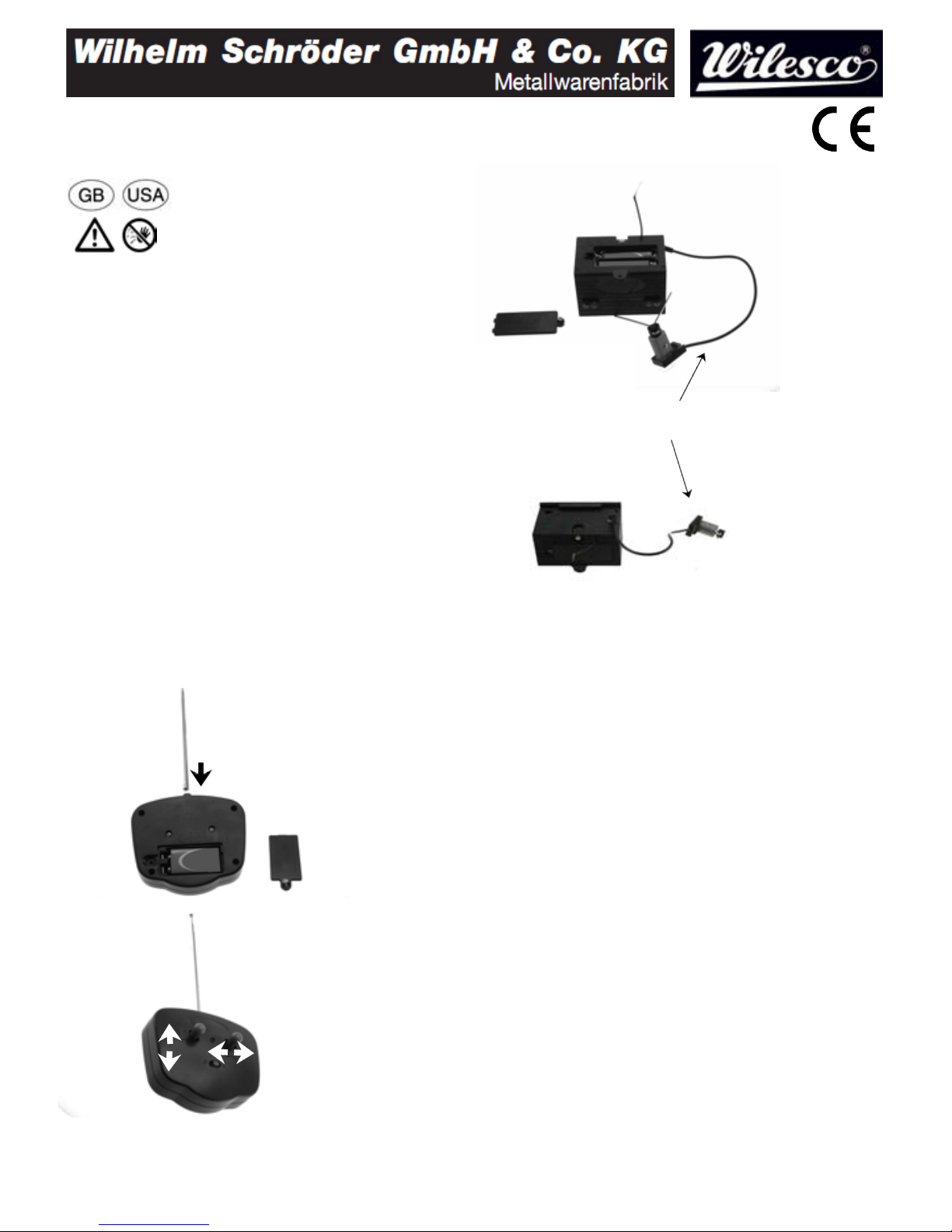
11. Unscrew the cover
of the battery
compartment and insert
a 9-V-monobloc
battery. Fix the cover
with the screw and
screw the antenna in the
thread.
12.Switchonthe
transmitter (position
on). The LED has to
come up. The right
switch controls the right
/ left direction, the left
switch controls the
forward / backward
direction.
13. Unscrew the cover
of the battery
compartment and
insert 2 1,5-Vbatteries type AAA
(observe correct
polarity+/-).Fixthe
cover with the screw.
14. Only for
supplementary set
Z363 to steer forward
and backward:
connect up the jack
plug.
15. The relevant installation instruction is described in the notes of each model (pages
3-6).
Use of batteries
16. Non-rechargeable batteries are not to be recharged.
17. Different types of batteries or new and used batteries are not to be mixed.
18. Only batteries of the same or equivalent type as recommended are to be used.
19. Batteries are to be inserted with the correct polarity.
20. Exhausted batteries are to be removed from the toy.
21. Supply terminals are not to be short-circuited.
Telecommunication regulations
22. Please observe the telecommunication regulations in the country in which you
want to drive your model. Theuserisresponsibleforthedueuseoftheradio
remote co ntrol. Please observe the legal situation in your country.
Indication of waste dispo sal
23. Environment protection also concerns Wilesco. You have the possibility to return
to us the remote control and also the original packing (freight charges are not
reimboursed). All returned remote controls / packing are professionally recycled. You
can also dispose of the electronic components professionally and according to the legal
prescriptions yourself by taking them to the recycle boxes in your community.
This model is meant for the above described purpose only.
Technical specifications subject to change without prior notice.
Schützenstraße 12 E-Mail: info@wilesco.de
D-58511 Lüdenscheid www.wilesco.de
Remote Remote Control Z360
forward
backward
only with
supplement Z363
right left
only with supplement Z363
Page 2
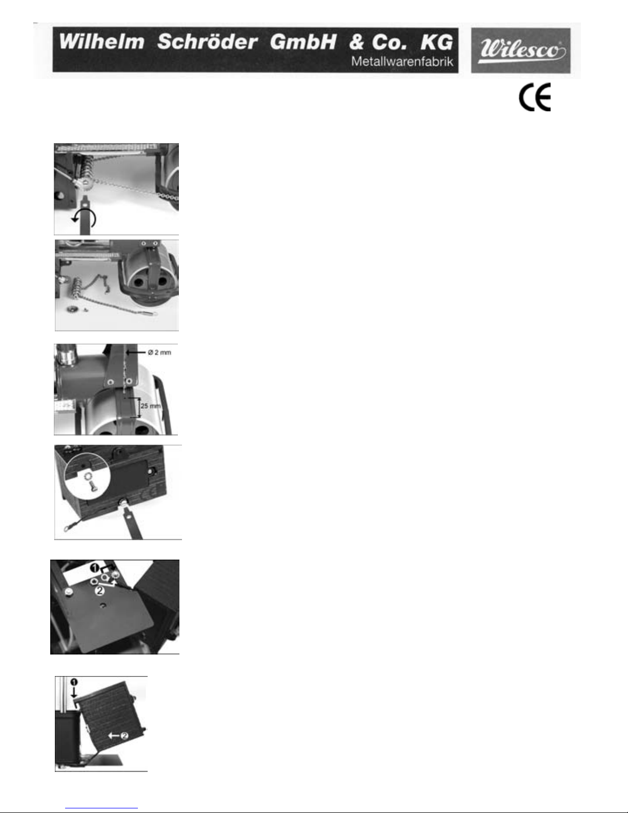
Demontage der Kettenlenkung Schraube gemäß Abbildung herausschrauben.
Disassembly of the chain steering Screw off the screw according to the picture.
Demontage der Kettenlenkung
Steuereinheit aus der Halterung lösen und die Federn aus dem Abstreifbügel aushaken.
Disassembly of the chain steering
Demount the steering unit off the bracket and unclasp the spring out of the scraper harness.
Bohrung für neuen Lenkdraht: 2-mm-Loch für den Lenkdraht bohren. Die Position ist dem Bild
zu entnehmen. Achtung: Das Loch nur durch das oberste Blech bohren.
Drill-hole for the new steering wheel: Drill a hole of 2 mm diameter for the steering wheel. You
can see the location on the picture.Watch: drill the hole only through the top metal sheet.
Montage des Empfängermoduls
Die Schraube M 2,5 herausdrehen. (Die sich hier befindliche Unterlegscheibe wird später an anderer Stelle noch benötigt.)
Assembly of the receiver module
Unscrew the screw M 2,5. (The washer of this screw will be used later on in another place.)
Montage des Empfängermoduls
Die beiden Muttern der Dachbügel unter dem Führerhaus lösen und das schwarze Schutzblech aufsetzen. Die linke Mutter mit beiliegendem Maulschlüssel wieder anziehen. Rechts den Sicherungsring, anschließend den Kabelanschluss des Empfängermoduls auflegen und mit der Mutter (Nr. 2)
festziehen.
Assembly of the receiver module
Loosen both screw nuts and roof-legs below the driver¶s cab and place the black protection shield.
Screw the the left nut with the enclosed wrench. Place the locking ring and then the cable junction of
the receiver box on the right side and fix it with screw No. 2.
Schützenstraße 12 58511 Lüdenscheid E-Mail: info@wilesco.de
Montage des Empfängermoduls
Das Empfängermodul oben einhängen und unten heranschieben gemäß Bild.
Assembly of the receiver module
Hang the top of the receiver box and push the bottom according to the picture.
Montage Fernsteuerung Z360 für Dampfwalze ÄOld Smoky³ D365 / D366 / D368
Zusatzblatt zur Bedienungsanleitung / Beides unbedingt aufbewahren?
Assembly of the radio remote control Z360 for steam rollers ÄOld Smoky³ D365 / D366 / D368
Supplement to the manual, please keep both!
Sender und Empfängerbox mit Batterien bestücken.
Fill the transmitter and the receiver box with batteries.
Page 3

Montage des Empfängermoduls
Das Empfängermodul mit der M2,5-Schraube durch das Loch in dem Schutzblech festschrauben.
Hinweis: Zum Batteriewechsel erst diese Schraube lösen und das Empfängermodul aushängen.
Nach dem Wechsel wieder wie oben beschrieben befestigen.
Assembly of the receiver module
Fix the the receiver module through the hole of the protection shield with screw M2,5. Nota:
When changing the batteries unsrew this screw at first. Fix it again after the change as discribed
above.
Montage des Lenkdrahtes
Den Lenkdraht durch die vorgesehene Bohrung schieben.
Assembly of the steering wire
Push the steering wire through the drilled hole planned for it.
Montage des Lenkdrahtes
Die Windungen des Lenkdrahtes bis zur Hälfte in die Empfängerbox einschrauben.
Assembly of the steering wire
Screw in the windings of the steering wire up to the half into the receiver box.
Montage des Lenkdrahtes
Den Lenkdraht leicht anheben und in der Bohrung justieren.
Assembly of the steering wire
Lift slightly the steering wire and adjust it in the drilled hole.
Sender und Empfängerbox mit Batterien bestücken. / Fit the transmitter and the receiver box
with batteries.
Da die Kettensteuerung für die Montage der Funkfernsteuerung demontiert werden muss, ist diese dann entgegen der Bedienungsanleitung bei dem umgebauten Modell nicht mehr zu nutzen. Technische Änderungen behalten wir uns vor.
The steam whistle and chain steering have to be removed for the assembly of the radio control. They can¶t be used any longer with the
changed model contrary to the operation instruction. Technical data can be amended without prior notice.
Montage des Lenkdrahtes
Die beiden Stellringe auf den Lenkdraht aufschieben und nicht festschrauben.
Assembly of the steering wire
Push both adjusting collars onto the steering wire. Don¶t tighten.
Fig. 1
Fig. 2
Fig. 3
Justierung der Lenkung
Sender und Empfängerbox einschalten und dann hiermit die Vorderwalzen so weit nach rechts
bewegen, dass zwischen Kessel und Walzen ca. 2 mm Abstand ist (Fig. 1). Die beiden Stellringe
gemäß Fig. 2 mittels der Madenschraube im linken Anschlag festziehen. Bei richtiger Einstellung ist nun bei Linkseinschlag die Begrenzung der Lenkung nach Fig. 3 gegeben.
Setting of steering
Set on transmitter and receiver box. Move the front rollers to the right as far as possible so that there is a gap of abt. 2 mm between boiler and roller (Fig.1). Fix both adjusting collars with the set screw on the left max. point (Fig. 2). If the setting is correct,
the steering to the left is now limited acc. to Fig. 3.
Page 4

Demontage der Kettenlenkung
Schraube gemäß Abbildung herausschrauben. Steuereinheit aus der Halterung lösen und die Federn aus dem Abstreifbügel aushaken.
Disassembly of the chain steering
Screw off the screw according to the picture. Demount the steering unit off the bracket and unclasp the spring out of the scraper harness.
Montage des Bügelhalters für den Steuerdraht
Den Bügelhalter gemäß Bild in Fahrtrichtung auf der rechten Seite der Vorderachse montieren.
Assembly of the holder for the steering wire
Fix the holder in driving direction on the right side of the front axle (see fig.).
Montage des Empfängermoduls
Die Schraube M 2,5 herausdrehen. (Die sich hier befindliche Unterlegscheibe wird später an anderer Stelle noch benötigt.)
Assembly of the receiver module
Unscrew the screw M 2,5. (The washer of this screw will be used later on in another place.)
Montage des Empfängermoduls
Die beiden Muttern der Dachbügel unter dem Führerhaus lösen und das schwarze Schutzblech aufsetzen. Die linke Mutter mit beiliegendem Maulschlüssel wieder anziehen. Rechts den Sicherungsring,
anschließend den Kabelanschluss des Empfängermoduls auflegen und mit der Mutter (Nr. 2) festziehen.
Assembly of the receiver module
Loosen both screw nuts and roof-legs below the driver¶s cab and place the black protection shield.
Screw the the left nut with the enclosed wrench. Place the locking ring and then the cable junction of
the receiver box on the right side and fix it with screw No. 2.
Schützenstraße 12 58511 Lüdenscheid E-Mail: info@wilesco.de
Bügelhalter
Holder
Montage Fernsteuerung Z360 für Dampftraktor D405/406 und Shoman¶s Engine D409
Zusatzblatt zur Bedienungsanleitung / Beides unbedingt aufbewahren!
Assembly of the radio remote control Z360 for traction engine D495/D496 and Showman¶s Engine D499
Supplement to the manual, please keep both!
Sender und Empfängerbox mit Batterien bestücken.
Fill the transmitter and the receiver box with batteries.
Montage des Empfängermoduls
Das Empfängermodul oben einhängen und unten heranschieben gemäß Bild.
Assembly of the receiver module
Hang the top of the receiver box and push the bottom according to the picture.
Page 5

Montage des Empfängermoduls
Das Empfängermodul mit der M2,5-Schraube durch das Loch in dem Schutzblech festschrauben.
Hinweis: Zum Batteriewechsel erst diese Schraube lösen und das Empfängermodul aushängen.
Nach dem Wechsel wieder wie oben beschrieben befestigen.
Assembly of the receiver module
Fix the the receiver module through the hole of the protection shield with screw M2,5. Nota:
When changing the batteries unsrew this screw at first. Fix it again after the change as discribed
above.
Montage des Lenkdrahtes
Den Lenkdraht durch die vorgesehene Bohrung schieben.
Assembly of the steering wire
Push the steering wire through the drilled hole planned for it.
Montage des Lenkdrahtes
Die Windungen des Lenkdrahtes bis zur Hälfte in die Empfängerbox einschrauben.
Assembly of the steering wire
Screw in the windings of the steering wire up to the half into the receiver box.
Montage des Lenkdrahtes
Den Lenkdraht leicht anheben und in der Bohrung justieren.
Assembly of the steering wire
Lift slightly the steering wire and adjust it in the drilled hole.
Da die Kettensteuerung für die Montage der Funkfernsteuerung demontiert werden muss, ist diese dann entgegen der Bedienungsanleitung bei dem umgebauten Modell nicht mehr zu nutzen. Technische Änderungen behalten wir uns vor.
The steam whistle and chain steering have to be removed for the assembly of the radio control. They can¶t be used any longer with the
changed model contrary to the operation instruction. Technical data can be amended without prior notice.
Biegen des Lenkdrahtes
Den Lenkdraht gemäß Skizze 20 mm vom Ende markieren. Den Lenkdraht mit Zangen so biegen, dass sich die Markierung anschließend in der Mitte des Radiuses befindet.
Bending of the steering wire
Mark the steering wire 20 mm from the end acc. to the illustration. Bend it with grippers so that
the marks are in the middle of the radius.
Page 6

This equipment has been tested and found to comply with the limits for a Class
B digital device, pursuant to part 15 of the FCC Rules. These limits are
designed to provide reasonable protection against harmful interference in a
residential installation. This equipment generates, uses and can radiate radio
frequency energy and, if not installed and used in accordance with the
instructions, may cause harmful interference to radio communications.
However, there is no guarantee that interference will not occur in a particular
installation. If this equipment does cause harmful interference to radio or
television reception, which can be determined by turning the equipment off and
on, the user is encouraged to try to correct the interference by one or more of
the following measures:
噝 Reorient or relocate the receiving antenna.
噝 Increase the separation between the equipment and receiver.
噝 Connect the equipment into an outlet on a circuit different from that to which
the receiver is connected.
噝 Consult the dealer or an experienced radio/TV technician for help.
Caution: Any changes or modifications to this device not explicitly approved by
manufacturer could void your authority to operate this equipment.
This device complies with part 15 of the FCC Rules. Operation is subject to the
following two conditions: (1) This device may not cause harmful interference,
and (2) this device must accept any interference received, including
interference that may cause undesired operation.
 Loading...