

Page 1

1
Steambox D 100 E
E-Box E 50
Page 2

2
Page 3
3
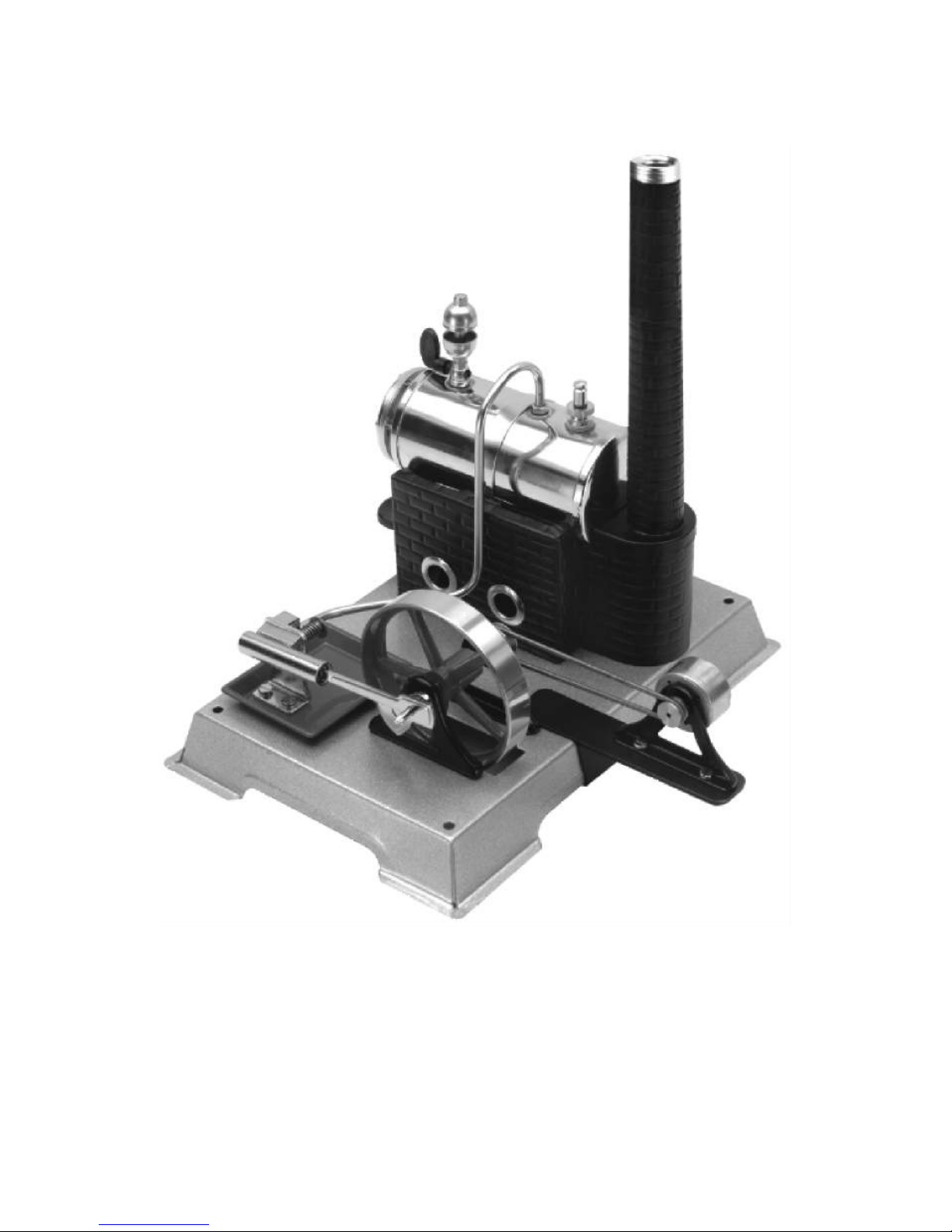
Steambox D 100E and E-Box E50
Wilhelm Schröder GmbH & Co. KG
D-58511 LÜDENSCHEID Schützenstraße 12
phone : +49 - 2351 - 9847-0 e-mail : info@wilesco.de
Page 4
4
Important information:
Please read the instructions carefully before using the product. There you
find important information for a successful use.
Any damages caused by not following the instructions or the safety advices
will not be treated as guarantee cases!
We do not take any responsibility in case of following up damages!
All the information has been worked out with great care. On the other hand
one cannot exclude that mistakes may happen. We kindly advise you that
neither Wilesco nor the author will take any guarantee cases, juristically
responsibilities or assume any kind of liability as consequences of wrong
instructions or experiments.
Wilesco invites to send comments about possible mistakes via mail.
A symbol in a triangle is indicating a possible dangerous
situation, which needs more caution and attention.
Imprint:
This is a publication from Wilesco©, Wilhelm Schröder GmbH & Co KG, D-58511
LÜDENSCHEID. All rights including translation are reserved. Any reproduction, f. ex. photo
copies, microfilming, electronic data processing need a written permission of the author. Prints,
also only parts, are forbidden.
This publication has the technical update at moment of print. Changes of technical nature and
equipment are reserved.
© Copyright 2012 by Wilesco, Wilhelm Schröder GmbH & Co. KG
Dampfbox D 100E: EAN 4009807051013
E-Box 50: EAN 4009807012502
Set: Dipl. Ing. Thomas Schröder, Ulrich Stempel
Author: Ulrich Stempel
Translation: Ulrike Krampen
Wilhelm Schröder GmbH & Co. KG
D-58511 LÜDENSCHEID Schützenstraße 12
Telefone : 0049 - 2351 - 9847-0 Fax : 0049-2351-9847-47
e-mail : info@wilesco.de
Page 5

5
Preface:
With this Steam Box or the E–Box 50 in combination with a steam engine
model and the booklet one can experience practically how the steam engine
and the transformation into electricity functions. Wilesco has joined for you
all the needed components in the Steam Box D 100E and the E-Box 50.
You are the owner of the Steam Box D 100E and now you build step by
step your own steam engine as a model. Through joining the different parts
one gets aware of the developed concept and the principle of the steam
engine, which has been invented by Denis Papin, James Watt and others.
This model does not only help to understand how a steam engine works, it
also creates a lot of joy to develop it even further.
With the Steam Box and the E-Box 50 and its components you can
practically experience and understand the transforming processes,
beginning with the thermo energy, through the mechanical energy and
finally turned into electrical energy. The experiments are structured and
build up one on the other. They are easy and in short time to realize.
In the booklet you also find information about the modern standard of the
steam engine and examples and possibilities of developments in the present
time.
I also would like to bring you this beautiful hobby of steam engine model
construction a little closer and wish you a lot of fun building this and other
steam engine models and the experiences you gain with it.
Yours
Ulrich Stempel
Page 6

6
Page 7

7
Inhaltsverzeichnis
1. BASICS ABOUT THE STEAM ENGINE........................................... 9
1.1 THE STEAM ENGINE AND ITS DEVELOPMENT....................... 9
1.2 KNOWLEDGE ABOUT THE STEAM ENGINE........................... 10
1.2.1 How to change water into steam .............................................. 10
1.2.2 The boiler.................................................................................. 11
1.2.3 The flywheel.............................................................................. 11
1.2.4 The oscillating steam engine .................................................... 11
1.2.5 The valve-controlled steam engine........................................... 13
1.3 POWER AN EFFICIENCY ............................................................. 14
1.3.1 Comparison: oscillating and valve-controlled steam engine... 14
1.4 WHAT FUNCTION HAS THE STEAM ENGINE NOWADAYS. 15
1.4.1 Hybrid systems consisting photovoltaic constructions and the
steam engine ...................................................................................... 15
2. ASSEMBLING THE MODEL............................................................. 17
2.1 TRICKS AND TIPS FOR A SUCCESFUL ASSEMBLING ........ 17
2.2 ASSEMBLY INSTRUCTIONS STEP BY STEP............................ 18
Step 1: Assembly of the boiler ........................................................... 18
Step 2: Mounting the burner slide and boiler house......................... 18
Step 3: Assembling and mounting the flywheel ................................. 19
Step 4: Assembling the cylinder unit ................................................. 20
Step 5: Mounting the steam pipe, chimney and final assembly......... 21
2.3 PRECAUTION INSTRUCTIONS................................................... 23
2.4 PREPARATION FOR THE FIRST TEST RUN ............................. 25
3. EXPERIMENTS WITH THE STEAM ENGINE AND
ADDITIONAL COMPONENTS............................................................. 29
3.1 THE COMPONENTS AND THEIR DESCRIPTION..................... 29
3.1.1 The Generator........................................................................... 29
3.1.2 Transmission belt...................................................................... 30
3.1.3 The bread board ....................................................................... 31
3.1.5 LEDs......................................................................................... 33
3.1.6 Electrolytic (Electrolytic capacitors) ....................................... 34
3.1.7 Diode ........................................................................................ 36
3.1.8 Resistors.................................................................................... 37
3.1.9 Crocodile clips (red/black)....................................................... 38
3.1.10 Hook-up wire (red/black) ....................................................... 38
3.1.11 Switch...................................................................................... 39
Page 8

8
3.2 FROM THE MECHANIC ENERGY TO THE ELECTRIC
ENERGY................................................................................................ 41
3.2.1 Connection and function of the current machine ..................... 41
3.3 FIRST EXPERIMENTS WITH THE GENERATOR ..................... 42
3.4 ROTATION DIRECTION INDICATOR ........................................ 43
3.4.1 The transfer of the circuit......................................................... 43
3.4.2 The technical and the real current direction............................ 46
3.5 MOUNTING THE GENERATOR .................................................. 47
3.5.1 Generator, to connect mechanically with the flywheel of the
steam engine ..................................................................................... 48
3.5.2 Measuring the voltage of the generator ................................... 49
3.5.3 The direction of the rotation of the steam engine and the
generator ........................................................................................... 51
3.6 USING STEAM ENERGY TO GENERATE ELECTRICITY....... 52
3.6.1 Evaluating the power of the steam engine and of the
generator ........................................................................................... 52
3.7 STEP BY STEP GENERATING BRIGHT LIGHT OUT OF
STEAM .................................................................................................. 55
3.7.1 More light with 2 white LEDs................................................... 58
3.7.2 Light from four LEDs generated throught the steam engine.... 59
3.8 STORAGE OF THE ELECTRIC ENERGY.................................... 61
3.8.1 Charging the capacitor storage through the steam engine...... 61
3.8.2 Diode blocking discharge, Schottkydiode ................................ 64
3.8.3 Charge indicator for the electrolytic........................................ 66
3.8.4 Using stored energy.................................................................. 69
3.8.5 The steam engine as a charging station for the torch .............. 70
4. ANNEX................................................................................................... 73
4.1 COLLECTION OF THE FORMULARIES..................................... 73
4.1.1 Voltage, current and resistance................................................ 73
4.1.2 Parallel circuit of resistors....................................................... 74
4.1.3 Series connection of resistors................................................... 75
4.1.4 Calculation of the power .......................................................... 75
4.2 TROUBLESHOOTING................................................................... 75
4.2.1 The steam engine ...................................................................... 76
4.2.2 The electronic ........................................................................... 76
4.3 SUPPLIER SOURCES FOR SPARE PARTS AND ELECTRONIC
PARTS.................................................................................................... 77
4.3.1 Consumable supplies for steam engines................................... 77
4.4 WARRANTY................................................................................... 78
Page 9

9
1. Basics about the steam engine
Steam engines are heat engines and they work in contrary to the combustion
motors without inner combustion. Mechanical energy is provided through
the pressure of the steam. One can use different sources of heat to make the
engine work; so all liquid, solid and gaseous fuels. Steam engines are also
capable to transform solar energy and growing fuels for our needs. They do
this in a low emission and climate neutral way.
1.1 The steam engine and its development
Constructions and their precursors, which work with steam pressure, have
been already used in the Greece antique. It is described that the doors of the
temple after lightening the holy fire would open in a magic way due to a
construction which worked with steam.
Leading steps in the development of the steam engine principles happened
during the time of the industrial revolution, f. ex. through Denis Papin. 1690
he invented the pressure cooker, where he developed a first prototype of a
steam engine with cylinder and piston. In 1698 the British engineer Thomas
Savery constructed an engine, working on steam, which was supposed to
pump the groundwater. In 1712 the engineer Thomas Newcomen developed
the principle even further into an atmospheric steam engine.
Information:
The atmospheric steam engine is a precursor model with the following
function: water steam is pressed into the space of the cylinder below the
piston, which cools down through added cold water and finally condenses.
This causes a negative pressure and because of the higher external
atmospheric pressure now the piston is pressed into the cylinder. Through
the flywheel mass and the opened steam valve the piston is again pressed
into the cylinder. The energetic efficiency of this construction is about
1%.
In 1769 James Watt managed to patent a double functioning steam engine.
In this construction the piston is alternately shifted from one side to the
other through steam. This increased the efficiency enormously. James Watt
described the out put of his engine in horsepower, which had been used as a
measurement for power engines for a long period of time, f. ex. with
automobiles.
Page 10

10
At that time the steam engine brought a lot of possibilities in the areas of
transport and construction. From the first rotation on the engine brings a
high torque to the axis and is able to work forwards and backwards. Steam
automobiles can start moving under load and do not need clutch and
gearing.
1.2 Knowledge about the steam engine
Right behind the wind power the steam power is one of the ancient methods
of humankind to produce mechanical energy. The name steam engine is
already indicating the energy source; steam. The energy source steam was
and is transformed into other energy forms through different constructions,
f. ex. piston steam engine or steam - turbines.
Basically we need two components regarding to the principle of the steam
energy: the steam boiler and the piston steam engine or the steam – turbine.
This principle has not changed till nowadays. Still changes have happened
within the modern steam engine regarding to the technical designs, modern
materials and a profound knowledge how to increase the efficiency.
In earlier times the efficiency of the piston steam engine was very low.
Especially to generate electricity they were mainly substituted through
steam turbines, which worked more efficiently. Nowadays functioning
nuclear power bases are so to speak modern steam engines, working with
the same principle. Here one uses the problematic nuclear energy to heat up
the water.
1.2.1. How to change water into steam
To transform the liquid state of H2O into water steam, we need to heat it up
till it boils. Once the water is boiling, which normally happens at 100
degrees C and 1013 hPa (the boiling temperature depends on the altitude of
the place, more exact - on the external air pressure) it changes into steam.
The boiling temperature of water (in general with liquids) changes when the
external air pressure raise. Assuming we have 2 bar pressure in the steam
boiler the boiling temperature raises up to 120 degrees C (theoretical value).
The heating up needs a certain quantity of energy which is called heat of
evaporation. There are needed 4,2 joule to heat up 1 gram of water for 1
degree C. On the other hand it needs 2257 joule to evaporate 1 gram of
water. This high energy consumption can be explained through the
enormous expansion of the volume of the water steam in relation to its
liquid state.1 litre of boiling water will transform into 1673 litres of steam
(these values are related to normal air pressure).
Page 11

11
Keeping the arising steam in a closed vessel will produce a very high
pressure, which can even lead to an explosion of the boiler.
Therefore the steam engines have safety valves which open with high
pressure so the steam can escape.
One uses the pressure of the steam by moving a piston in a cylinder, which
produces mechanical energy.
Information:
In physics we use the parameter “p” for pressure, which acts with a power
“F” on a surface “A”.
When the steam cools down a contrary process is taking place, the steam
condenses. Now the energy which has been used to evaporate is set free.
Water steam condenses f. ex. on colder metals and is then visible in little
water drops.
1.2.2 The boiler
There are different designs of the steam boiler depending on the use and
form of the steam engine. The main intension is to provide constantly
enough steam so that the pistons of the steam engine are moving.
1.2.3 The flywheel
The steam engine transforms the back- and forward movement into a
rotating movement.
The classical steam engine has a heavy flywheel to provide an even
rotation. This helps to overcome the upper and lower dead centres. The
flywheel is an energy storage, which stores the energy of the “power
strokes” and therefore bridges the passive time.
1.2.4 The oscillating steam engine
With the help of the oscillating principle one easily can realize a
functioning steam engine model. The oscillating steam engine regulates the
in and outlet of the steam through the moving cylinders. Constructions of
centred rotatable bearings provide the needed flexibility of the cylinder.
Through a coil spring the cylinder is compressed against the holder. The
sliding surfaces need to be even.
Page 12
12
Fig. 1.01: The oscillating cylinder:
steam engine model of the steam box
On the back of the cylinder we find a hole which is called steam hole. On
the connected surface of the fixing bracket we find a steam supplying hole
and a steam exhausting hole. Steam enters into the cylinder when the steam
hole of the cylinder is exactly positioned on top of the steam supplying
hole. The piston moves out of the cylinder and the lifting movement is
transformed into a rotating movement through the rod bearing and the crank
(eccentric bearing). The flywheel mass leads the piston back so that the
cylinder is tipping backwards with its steam hole on top of the steam
exhausting hole and the used steam escapes. When the piston has overcome
the rear dead centre the steam hole moves again on top of the steam
supplying hole, steam enters the cylinder again and the explained process
repeats itself.
The principle of the oscillating steam engine
The water steam provided by the boiler enters through the steam supplying hole into the cylinder and presses the piston out of the cylinder. Through the crank movement the cylinder moves on and the
steam inlet is closed.
Through the uplifting movement of the piston the cylinder moves on
and reaches the steam exhausting hole. The cooled water steam is
pressed out and escapes to the sides. The process starts again.
The advantage of this type of engine is a much easier construction. It is a
complete and powerful engine and was used in steam navigation.
Page 13
13
1.2.5 The valve–controlled steam engine
Contrary to these simple constructions there are also valve-controlled
models available, such as the steam engine model D9/D10, D20 and other
models from Wilesco.
The valve-controlled steam engine works like this:
Water steam provided by the boiler enters the slide box and a slider presses
on one side of the piston within the cylinder. The high pressure steam
pushes the piston into the cylinder. As the piston is connected with the
crankshaft through a connecting rod the flywheel now turns on half a
rotation. Now the slider is moved. The steam feed happens now on the other
side of the piston, which is then pressed backward through the steam.
The cooled steam leaves through the steam outlet, f. ex. through the
chimney of the steam engine model. The process starts again.
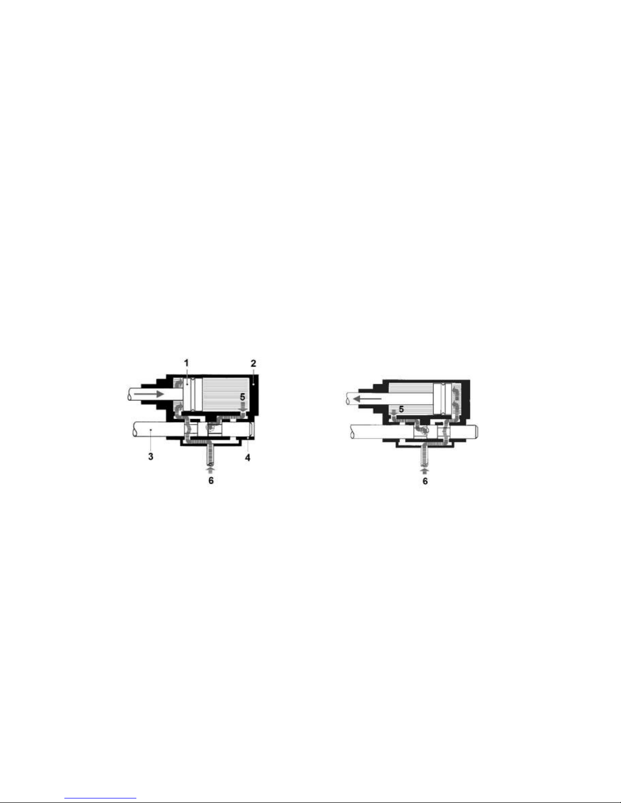
Fig.1.02
The principle of the valve-controlled steam engine (a cut through cylinder
and slider) a) steam presses the piston (1) to the right, b) to the left. 1=
piston, 2= cylinder, 3= slider rod, 4= slider box, 5= steam outlet, 6= steam
inlet
The steam engine can consist out of one or several cylinders. The advantage
of several cylinders is a continuous power transfer.
Page 14
14
1.3 Power and efficiency
One of the real advantages of the steam engine is that through the external
combustion he does not depend on high quality fuel. He works with any
kind of fuel, f. ex. coal, wood, oil, peat, any kind of waste etc. This is not
true for the steam engine model, they are fed with dry spirit tablets. Another
advantage of the steam engine is that they produce relatively little operating
noise. What one can hear is the noise of the mechanics and the exhaustion
of the steam, the engine itself runs almost silent.On the other hand we have
a very essential disadvantage. The steam engine has a very low efficiency;
only 10 to 12%, which means only 12% of the involved energy of the fuel is
transformed into kinetic energy.
1.3.1 Comparison: oscillating and valve-controlled steam
engine
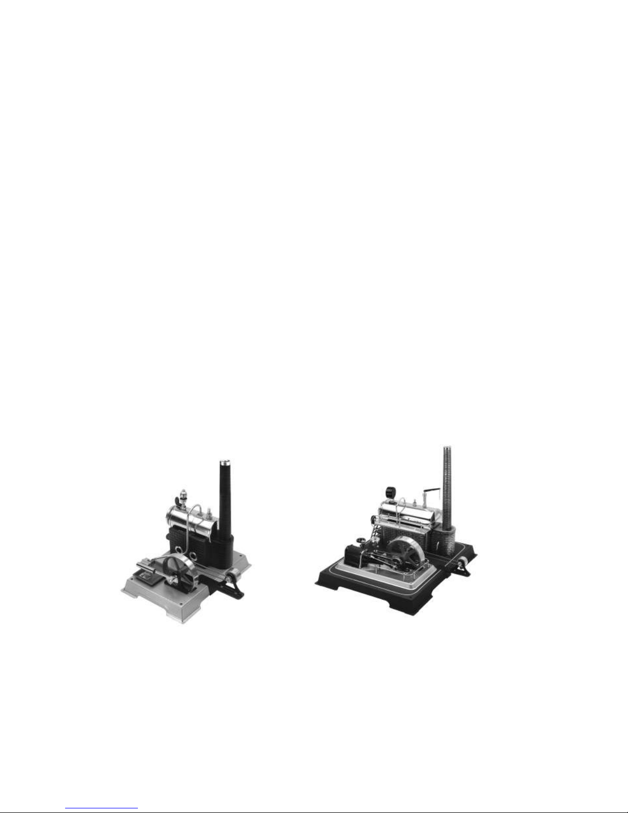
With the model Steam Box and the model D20 one can explore easily the
difference between the oscillating and the valve-controlled steam engine.
Also with the experiments of the Steam Box one can point out the
differences very clearly.
Fig.1.03 on the left side the steam engine model of the Steam Box with the
oscillating cylinder, to the right the model D20 (valve-controlled).
Page 15

15
Beside the different technical structures both models also differ in power
transfer and efficiency. For the same amount of power the Steam Box
model needs more fuel then the D 20 model. The generator is excellent to
explore the power transfer.
1.4 What function has the steam engine nowadays?
In the area of the power engines the steam engine was substituted through
the combustion engine. Because of the high energy content of the fuel (1012 kWh per litre) one gains a higher efficiency together with less weight
and more comfortable operation. Today there are still areas of use for the
steam engine. These constructions are used in the coal mining and conveyor
belts. Here the steam engine works as well as a winding machine for coal
and at the same time as a brake to let down filling material. The kinetic
energy which is produced through the letting down movement is used to
heat up the steam.
Now and again there are engineers who pick up the principle of the steam
engine and bring it into the world with modern materials. One advantage to
the combustion engine is the external combustion process and the use of a
variety of fuels. Another one is the overload capacity of the steam engine.
Overload capacity means that the nominal value and the continuous power
transfer can be shortly and without problems exceeded. One can prove this
in the described experiments, f. ex. by short-circuiting the generator.
Modern steam engines with low emission combustion produce steam
efficiently and then similar like a diesel engine they inject the steam
through nozzles. Those engines work in the 2-stroke process and do not
need common lubricants, because the mechanical parts are made out of
carbonic components.
1.4.1 Hybrid systems consisting photovoltaic constructions and
the steam engine
There exist different explorations and examinations regarding to hybrid
systems consisting modern photovoltaic in combination with modern
concepts of the steam engine.
These combined systems make sense in climate regions where solar energy
mainly is used in the summer season and a complement is needed for the
Page 16

16
winter season. A combined heat and power production serves well, mainly
for the heating season. Systems like this provide f. ex. for private
households or internal consumers, an all year round and energy selfsufficient concept.
Instead of the steam engine one also can use a Stirling engine. Both
constructions can work with all kinds of solid and liquid fuels, f. ex. wood,
coal, biogas etc.
Information: If you work with the E-Box 50 or a different model you can
skip this chapter (2) and move on to the next (3) and continue to
experiment with the steam engine model you have.
Page 17
17
2. Assembling the model
Depending whether you work with the Steam Box D100 E or you already
have a fixed model this chapter continues with putting together the steam
engine model. The following chapter shows experiments with an already
existent steam engine model.
2.1 Tricks and tips for a successful assembling
Sometimes it seems a little difficult to screw in some screws in an
inaccessible positions, like in the area of the flywheel. It is very useful to fix
a little magnet on the screwdriver so that it becomes magnetised. Now the
screw can easily be lead to the prepared drilled hole.
Fig.2.01:
Screwdriver becomes
magnetised and holds the
screw.
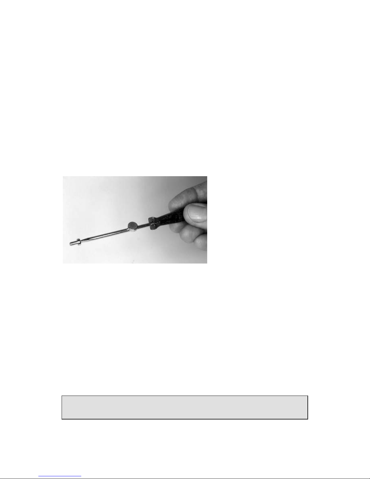
To tighten the screw properly it makes sense to use the screwdriver on the
one side and on the other side hold the screw-nut with a spanner.
It is helpful to put all the small pieces like screws, nuts and seals into a flat
container so they do not get lost.
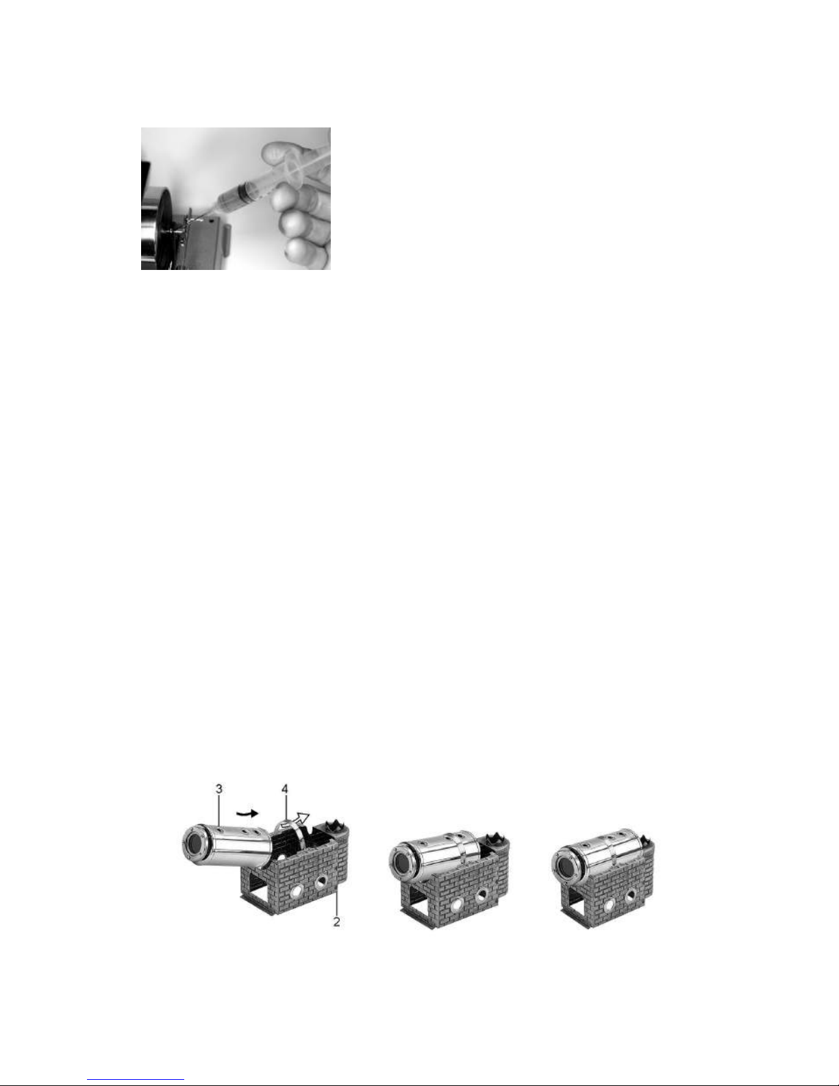
How to lubricate the moving parts:
A good service brings a small disposable syringe, with a blunt needle (the
peak of the needle can be cut of or grinded down). This allows injecting the
steam engine oil well measured onto the oil needing parts.
Do not use any liquid oil for lubricating the piston and cylinder. Please
only use Wilesco steam engine oil.
Page 18
18
Fig. 2.02: Lubricating with a disposable syringe
Before lightening the dry spirit tablets check whether the burner slide
moves easily in and out of the burner slide box (in the boiler house of the
steam engine model). If not you can slightly widen the sides of the burner
slide box.
2.2 Assembly instructions step by step
All the parts that you require to build this steam engine, including the tools,
are contained in the Steam Box D 100E. The instruction leaflet is divided
into assembling steps, and each step is illustrated.
Please follow the instructions exactly and step by step, so that the operation
of the steam engine is successful.
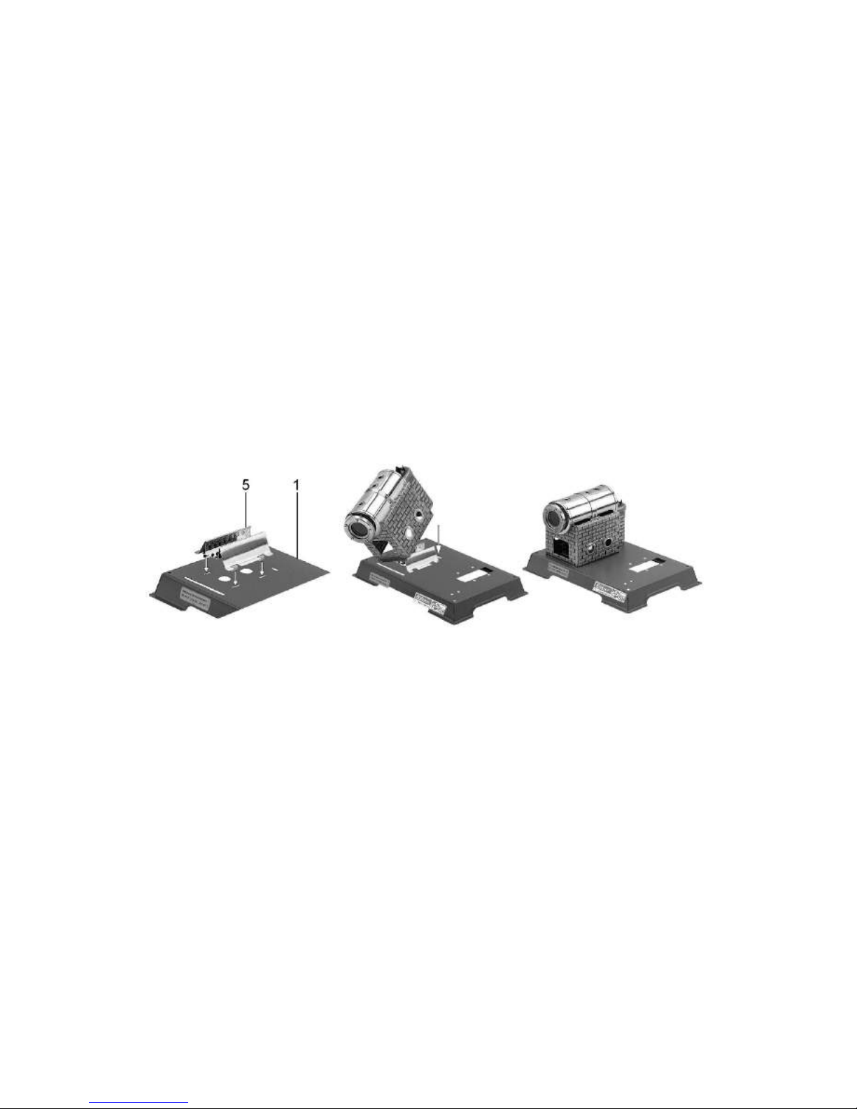
Step 1: Assembly of the boiler
Insert the fixing bracket of the boiler through the boiler house (2) from
beneath until the angled sides fit against the upper flanges of the boiler
house (2). Locate in the centre notches to restrict sideways movement, now
the bracket will stay in place due to its own tension. Push the boiler (3)
according to the Fig. 2.2.1 (The water level glass has to stay on the side of
the fire place) between the fixing bracket (4) and the boiler house. Now
push the boiler up against the bracket, and at the same time slide it forwards
until it locks on the rear boiler support.
Fig. 2.2.1: mounting the boiler
Page 19
19
Step 2: Mounting the burner slide and boiler house
CAUTION work carefully because of sharp edges! Insert the tabs on the
burner slide (5) with the point facing towards the front into the
corresponding slots on the base plate (1). Turn the base plate (1) over, and
tap the burner slide tabs outwards, using the screwdriver handle. This is best
done by resting the burner slide on the edge of a table.
Now insert the long tab on the boiler house into the long slot in the base
plate (1), locate the remaining two tabs into the corresponding slots and tap
these over as well. This is best achieved by resting the chimney vent on the
edge of the table. Attach the stickers “watch water level” on the base plate
(1) under the water level glass and the sticker of the model number next to
it.
Fig.2.2.2: mounting the burner slide and the boiler house
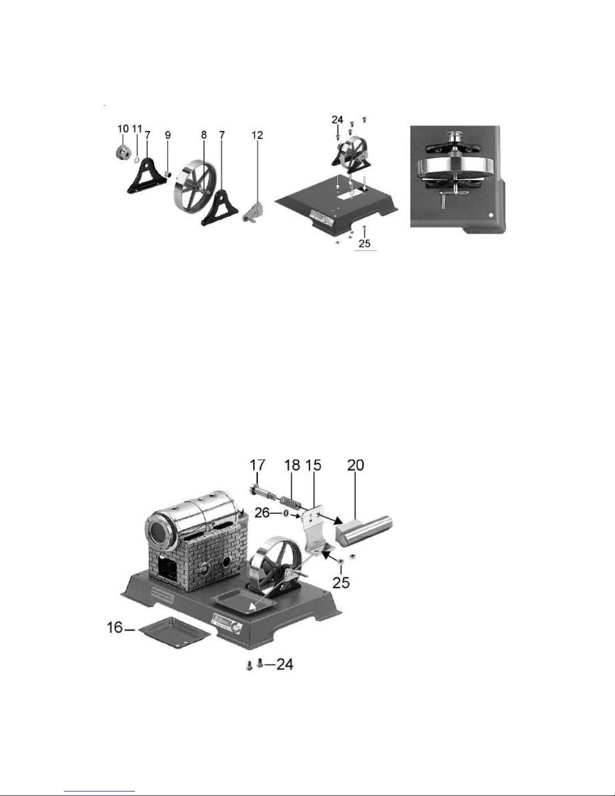
Step 3: Assembling and mounting the flywheel.
On the short side of the flywheel axle (8) fit one bearing frame (7) and then
screw on the crank plate (12). On the other side of the axle slide onto in the
following order the distance bush (9), the second bearing frame (7) and 1
washer (11), then screw on the pulley wheel (10) again. Now tighten the
crank plate (12) and the pulley wheel (10) against each other. This flywheel
unit is now fixed onto the base plate (1) using the screws M3x6 (24) and the
nuts (25) so that the crank plate faces towards the outside.
To mount this part is a little difficult, so please look under tricks and tips
using the idea with the magnet on the screwdriver.
Page 20
20
Fig.2.2.3: mounting the flywheel
Step 4: Assembling the cylinder unit.
Mount the cylinder unit first by fitting the spring (18) and the baffle plate
(15) onto the screw M3x16 (17). Now tighten her into the threaded hole on
the cylinder (20) by turning the screw only 1-2 times. Do not turn further
otherwise this will damage the cylinder. Now fit the baffle plate and the
condensed water tray to the base plate using two screws (24) and nuts (25).
Insert the screws from underneath the base plate.
Fig.2.2.4 mounting
the cylinder unit
Page 21
21
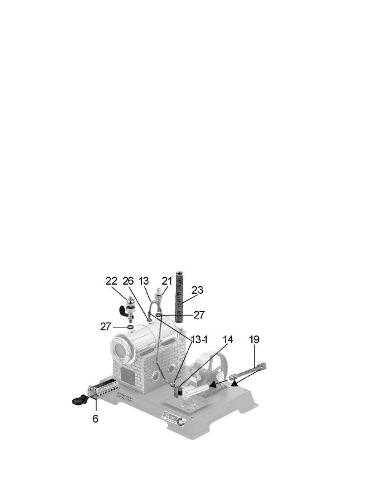
Step 5: Mounting the steam pipe, chimney and final assembly
On the boiler are three threaded holes. Put a gasket (26) into the middle one
and in the threaded bush on the baffle plate (15). Slide the cover (14) over
the packing screw (13-1) on the baffle plate end of the steam pipe (13) and
lightly ( first by hand) screw both ends of the steam pipe into the gasketed
holes. Now insert the piston rod (19) into the cylinder and over the crank
plate (12) pin. Check that the cylinder is at right angles to the flywheel axle,
are any adjustments necessary loosen the nuts holding the baffle plate,
adjust and retighten. Now with the use of the supplied spanner tighten the
steam pipe connections. Put a large gasket onto the whistle (22) and the
spring loaded safety valve (21) and fix it by hand (not using a tool) on the
boiler. Using a combination of gaskets you can position the whistle
correctly and tighten both by hand. Insert the burner tray (6) under the
boiler and fit the chimney (23) over the vent and fix it with 2 metal screws.
Now the assembling of the steam engine is finished. Stick on the sticker:
Baumusterprüfung vom TÜV/Nord
Fig.2.2.5:
Final
assembling
Page 22
22
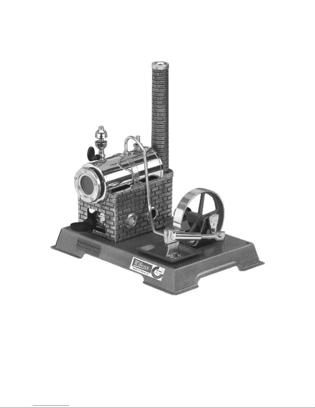
Fig 2.3.1: A complete steam engine model without generator
Before operating read the instructions carefully. We wish you lots of fun in
building and operating this steam engine.
Page 23
23
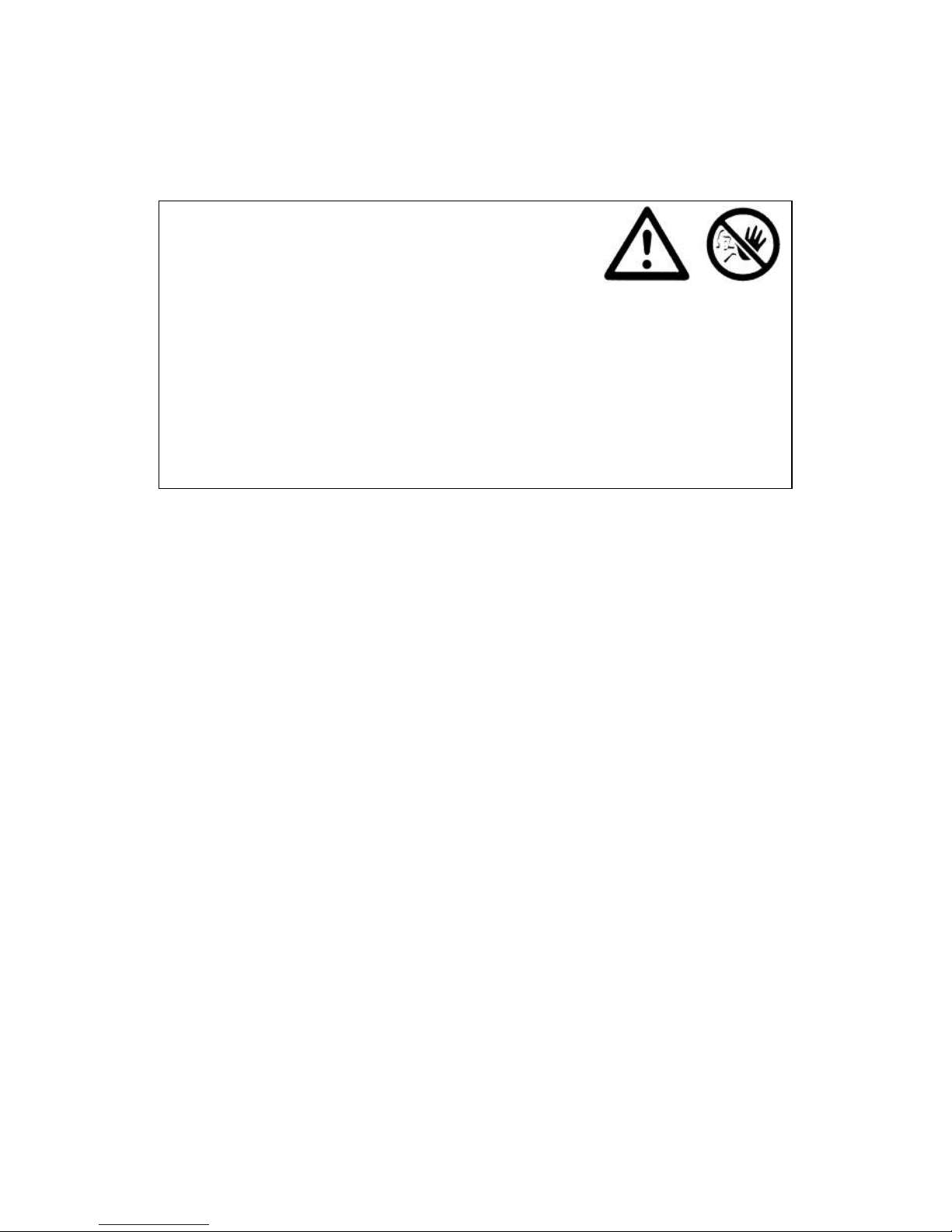
2.3 Precaution instructions
Attention! Important information and safety
precautions for your own safety:
1. For safety reasons, children should run the steam engine only under
supervision of adults (recommended age: from 8 years on, not
recommended for children under 36 months). During the operation of
the steam model until its complete cooling the engine must be under
constant observation.
Important!
Never operate the engine without safety valve. Only use WILESCO
steam engine oil and dry fuel tablets!
1. Each irregularity during operation has to be repaired by a competent
and authorized person or by WILESCO themselves. Otherwise any
warranty expires.
2. Any unauthorized change, repair or manipulation to the standard
specification will also invalidate the warranty.
3. All parts which are under steam pressure so as boiler, spring loaded
safety valve etc. leave our works only after a 100% examination. The
spring loaded safety valve must not be manipulated. The operation of
the steam engine without any spring loaded safety valve is not
allowed The function of the spring loaded valve has to be checked
before each operation by pressing the spring or by a small pull on the
upper valve rod. If lime residues caused by hard water are visible on
the spring loaded safety valve, it has to be replaced immediately.
4. High temperatures: The principles on which the engine works mean
that the burner slide, boiler, boiler house, the spring loaded safety
valve, the steam pipes etc. become very hot. Do not touch in order to
avoid the risk of burns.
5. Safety precautions: in the course of the running, take care that children
do not touch any of the moving parts.
Page 24

24
6. Danger if the boiler is heated without enough
water! Always ensure that there is enough water in
the boiler of the steam engine. Caution: When
refilling WiTabs dry fuel tablets also refill up to the
max. level.. The water must always be visible at
least at the lower end of the sight glass, otherwise
the joints become leaking and the boiler will be destroyed. Any
resulting claim, damage or consequential damage cannot be accepted.
7. If the boiler or any steam leading part leak, stop the steam model
immediately by removing the burner slide. Any necessary repair
should be carried out by authorized staff or at the WILESCO
company.
8. The steam engine meets all safety standards and actual regulations.
Every boiler has been submitted to a bursting pressure and water test
of 5 bar. The operating pressure is maximally 1,5 bar.
9. Imperatively keep the operating instructions together with your steam
box.
10. We advise you to place the stationary steameEngine on a non sliding
surface or fix it onto a coated chipboard (approx. 16 mm thick) with 4
wooden screws (3,4 x 45 mm). The size of the board depends on how
many models will be running with the steam engine.
Caution: Don't operate the steam model near flammable objects or on a
temperaturesensitive surface. Operation only under windless condition.
Page 25

25
2.4 Preparation for the first test run
Components: distilled water, steam engine oil, dry spirit tablets
Please operate the steam engine model only according to the instructions
and the safety instructions.
Operating instructions
1. Filling with water at the first operation and after cooling of the boiler:
Unscrew the spring loaded safety valve and fill the boiler with the
funnel up to the water level maximum (upper end of the sight glass), if
possible with warm water. Lift the funnel slightly during filling so that
the air inside the boiler can escape. Use only deficient in lime water or,
even better, water without any lime (e.g. distilled water). Then refit
the spring-loaded safety valve.
2. Screw the steam whistle onto the boiler. When screwing in the steam
whistle, the lever should point outwards (use washers if necessary) so
that the operation of the whistle is possible without having contact with
the boiler. Do not pull or pull out the lever, only move it carefully from
side to side.
Note: The steam whistle makes it possible to regulate easily any overpressure in the boiler or check before oiling whether the boiler is still under
pressure.
3. Only oil the piston when there is no pressure in the boiler. To check
this, operate the steam whistle several times. When the piston needs to
be oiled remove the piston rod from the pin of the crank disk and apply
abt. 2-3 drops of Wilesco steam engine oil onto the piston and abt. 2-3
drops into the cylinder itself. 2-3 drops oil are sufficient for approx. 10
minutes operating time. Oil lightly all of the bearings and linkages.
Before refilling the boiler with water, check that no pressure is in the
boiler through operating the steam whistle.
4. Place 1 1/2 WiTabs dry fuel tablets upright in the burner
slide (not more than 1 1/2 pcs.) and light them. Use only
the original WILESCO burner slide. Caution:
Page 26

26
because of the risk of danger from an open flame, always take the
necessary safety precautions. The burner slide is adjustable. The
oxygen supply and the flame height can be adjusted by moving the
burner slide in relation to the air holes of the burner slide guide in the
boiler housing. Before adding new fuel tablets, always check the water
level and refill the boiler with water to ensure that the boiler does not
run dry. The portion of fuel tablets to the quantity of water in the boiler
is designed so that the boiler cannot run dry without any added fuel
tablets. The burner slide must be completely pushed in. Important:
After the heating process, remove the burner slide from the guide
whilst it is still hot, otherwise not burnt fuel may cause the slide to
stick. If the slide is stuck, it can be removed by tilting it slightly to the
left or right.
Caution: dry fuel tablets require a lot of oxygen to
burn properly. That is the reason why, for an indoors
use, the room should be well ventilated.
To prevent unpleasant smells, the fuel tablets should be burnt out they should not be blown out. If there is not enough water in the boiler,
place the burner slide on a fireproofed surface until the tablets have
burned out completely.
5. When steam can be seen turn the flywheel by hand to let the
condensation in the pipes and the cylinder escape. Then the steam
engine will start to operate.
6. After the use of the steam engine and its cooling, the engine should be
serviced. Pour out any water left in the boiler. For this, unscrew the
spring loaded safety valve and take off all of the loose parts before
tipping over the engine. Be very careful if the water is still hot! Water
left in the boiler cannot do any damage but might leave sediment on
the sight glass. Any lime formation on the sight glass or in the boiler
should not be removed by using vinegar or corrosive agent (advise: use
a lime dissolving agent which does not attack the brass and the solder).
The building of soot on the lower side of the boiler does not influence
the function and can be removed with a brush. Finally, dry the model
using a clean piece of cloth.
Page 27

27
Fig.2.3.2: Steam engine of the Steam Box with generator
Page 28

28
Page 29

29
3. Experiments with the steam engine and additional
components
Together with the added components and the steam model one now can start
to build electrical and electronic circuits.
3.1 The components and their description
Here are described the qualities and the use of the added components in the
Steam Box D 100E and the E-Box 50
3.1.1 The generator
You find a permanently excited current machine in the Steam Box D 100E
and the E-Box 50, which is used in the experiments mainly as a generator.
To be more precisely there does not exist any difference between an engine
and a generator. Depending on the use and the electrical wiring a machine
works as an engine or a generator.
The generator with its permanent excitement has the advantage to create the
field for induction/generating electricity through a permanent magnet
instead of using a coil. This construction saves energy which is normally
used to establish the electric field. In cases of low rotating speed of a steam
engine it avoids that there is more energy consumed then being produced.
The direct current generator has a rotor (a coil out of enamelled copper
wire), which turns within a constant magnet field (stator). This rotor coil is
connected through a brush-like commutator to the generator connections
(red and black connection cable). With each half rotation of the rotor the
commutator changes the polarity of the coil.
Fig.3.0.1: circuit symbol, generator
Page 30

30
Fig.3.0.2: direct current
machine with mounting
support
The connecting cables (red/black) are made out of flexible strand and can
be connected f. ex. with crocodile clips with the bread board.
3.1.2 Transmission belt
Through twisting the enclosed transmission belt it is joined together or
pulled apart. Therefore hold - likewise in Fig.3.0.3 – the left end and take
the right end and give it 1-2 turns to the left (a). Now the transmission belt
itself stays without tension. Take the conical end – in the Fig.3.0.3 the right
end - and stick it into the cylindrical end and screw it in with 1-2 turns. The
dismounting you do in the reversed order.
Fig.3.0.3: connecting
the transmission belt,
a) first step, b) second
step
The Steam Box contains transmission belts. One can cut with a strong
scissor the transmission belt into the right length. For the transmission of
the mechanical power of the steam engine to the generator a length of 175
to 185 mm is optimal. It is important to make the cut on the cylindrical end
and leave the conical end for putting together both ends of the belt.
Page 31

31
3.1.3 The bread board
The bread board, also called patch panel, consists in his inside contact
springs, which are connected to one another in a system of rows.
The bread board is excellent for realizing electronic circuits in combination
with the steam engine. The electronic parts, such as the LEDs, resistances
and connecting wires can be repeatedly used and inserted into the contacts.
It allows that the experiments can be configured without soldering or
screwing. One can design circuits and experiment with them by changing or
exchanging different components.
Dates: This bread board has 170 contacts in a 2,54mm grid. The 170
contacts in the middle range are each connected by vertical strips in rows of
five.
measurements: 45mm x 33mm x 9mm
distance of contacts: 2.54 mm (100 mil)
cable connection - size: 0.3 - 0.8 mm (AWG 20 - 28)
shape of the hole: rectangular
fixation: adhesive foil at the back side
Fig.3.04: bread board
Fig.3.05: internal circuit system of
the bread board (connection of the
contacts by vertical strips in rows
of five)
Page 32

32
When the bread board is new, initially it can be difficult to stick in the
pieces and wire jumpers. It helps to prepare the contacts with a thin needle,
which should not be thicker then 0,3 – 0,6 mm, otherwise the contact spring
wears out to an extend that the contacts to the wire connection might suffer.
Fig.3.06: carefully widen the
contact with a needle
All parts can be stuck in directly without soldering. It needs some practice,
so that the connection wires do not bend over. Hold the wire right at its end
and stick it vertically with a little bit of pressure into the contact. The use of
flat pliers can be helpful.
Cutting the end of the wire diagonally with a side cutter is also supportive.
Short wires – like you find at the LEDs – you stick in with flat piers or a
pincer, so they do not bend over. One can cut some jumpers with a diameter
of 0,6 mm out of the jumper wire.
Measure the approximately length of the jumper and add the length of the
ends, which will stick in the contacts. Remove the cable insulation at the
ends. Either you use a wire stripper or cut around the wire with a knife and
remove the insulation.
The bread board can be fixed on a surface, f. ex. a well proportioned
prepared piece of wood. The back side of the bread board has an adhesive
foil. Take of the protection paper and glue it now onto a plain and dust-free
surface.
Attention: Once you glued the bread board onto a surface it is difficult to
remove without damaging it.
Page 33

33
Fig.3.07: bread board glued
to a mounting board
(mounting board not
included)
3.1.5 LEDs
Compared to a normal diode the LED (light emitting diode) has one further
characteristic! It shines when voltage is applied. You find a red, an orange,
2 white shining LEDS and a red flashing LED. You can identify the
flashing LED through its black spot within its red enclosure. The dark spot
is the integrated circuit which causes the LED to flash as soon as the correct
voltage is applied.
LEDs should always be operated with a series resistor for current limiting,
otherwise they can break.
Fig.3.08: circuit symbol, LED, the arrow
shows the technical direction of the
electric current, A symbolises anode (+)
and K cathode (-)
Page 34

34
In some experiments together with the generator are series resistors with
100 Ohm to 1K-Ohm recommended.
Compared to the normal light bulb the LED does not have a filament. They
have a long durability and do not consume a lot of energy.
Fig.3.09: The connections of the LED: the longer
end of the wire is the cathode, the “negative
connection”, also marked through a flattened
enclosure
Fig.3.10: flashing LED with integrated flash-IC
3.1.6 Electrolytic (Electrolytic capacitors)
Electrolytic capacitors have a high capacity compared to normal capacitors.
One can imagine the capacitor with 2 metal plates (as it is usually shown in
the circuit symbol). The first “plate” insulated by an oxide-layer (dielectric).
The “second” plate consists out of an electrolyte, which gives the name to
the capacitor. Due to the electrolyte, an electrolytic capacitor is polaritydependent and the connections are designated with a positive pole and a
Page 35

35
negative pole. When it is connected “the wrong way around” over a longer
period, the electrolyte of the capacitor will be destroyed.
Do not exceed the imprinted maximum voltage indication, because
otherwise the insulation layer can be destroyed.
Enclosed you find radial electrolytic capacitors with the following
capacities: 1000µF and 4700µF
Fig.3.11: circuit symbol, electrolytic
capacitors, left the positive pole
Information: μF means “microfarad”; the unit μ is one millionth of the basic unit.
Fig.3.12: Electrolytic capacitor
with connecting wires. The
positive pole is the longer
connection wire. In addition the
negative pole is designated with
a bright line on the enclosure.
For simplicity, the term “electrolytic capacitor” is sometimes shortened to
“electrolytic”. This abbreviation is mainly used in the US.
Page 36

36
3.1.7 Diode
Diodes let the current pass in only one direction. For that reason, they are
used to rectify AC voltages and to block undesirable polarity with DC
voltage, among other things. You can picture the functioning of a diode in
normal operation most easily as a non-return valve (water installations).
When pressure (current) is directed onto the valve (diode) in blocking
direction then the current will be blocked.
Fig.3.13: circuit symbol, Scottkydiode,
the left side signed with A is the anode
(+), the right side signed with K is the
cathode (-)
The pressure has to built up in contrary direction (direction of the arrow) to
overcome the spring pressure of the valve. The valve opens and the current
flows. The pressure, which is mentioned in this mechanical model to
overcome the spring pressure, corresponds to the forward voltage of the
diode. A certain voltage in the flowing direction of the diode is needed to
move into a conductive state.
Fig.3.14: Schottykdiode, type
BAT48. The cathode of the
diode can be recognized by
the imprinted black ring, the
other connection wire is the
anode. The technical current
direction goes from the anode
to the cathode.
Information: With the enclosed Schottky diodes the current begins to flow
at 0,25V in forward direction (circuit symbol: arrow). This allows an almost loss-free transmission.
Page 37

37
3.1.8 Resistors
A resistor is a passive component in electric and electronic circuits. Its main
task is the reduction of the flowing current to “reasonable” values. The most
famous resistors are the cylindrical ceramic type with axial connection
wires. The resistance values are imprinted in the form of coded coloured
rings. Enclosed are carbon-film resistors with the different values, shown in
the following table.
amount
Resistor value
1. ring
1. number
2. ring
2. number
3. ring
Multiplicator
4. ring
Tolerance
1
1 Ohm
brown
black
gold
gold110 Ohm
brown
black
black
gold1100 Ohm
brown
black
brown
gold21 K-Ohm
brown
black
red
gold
Fig.3.15: to the left a photo of a resistor, to the right the circuit symbol of
the resistor. It does not matter on which side it is connected.
R = resistor
Page 38

38
3.1.9 Crocodile clips (red/black)
With the red and black experimental wires, which have the crocodile clips
on their ends, you can easy and fast connect and combine different electric
parts (without soldering). It makes sense to use the red wire for the positive
pole, the black one for the negative pole.
Fig.3.16: experimental wire
with crocodile clips
3.1.10 Hook-up wire (red/black)
Enclosed you also find hook-up wire. You can make jumpers by estimating
or measuring the approximate length of the jumper (plus the length for the
wire ends that will be inserted into the plug contacts). The ends are stripped
of insulation for ca. 8 mm. Connection wires pinched off diagonally with
the wire cutter make insertion in the bread board contacts easier. With these
wires you can establish the electric connections between the single contacts
of the bread board. Once the jumpers are made, they can be used again and
again.
Fig.3.17: Possible applications
of the hook-up wire. One can
see the pins for the connection
to the crocodile clips in the
upper contacts. The upper 5
rows are connected to the lower
5 rows.
Page 39

39
3.1.11 Switch
According to the figure you find one switch. This type with 2 connections is
suitable for the use on the bread board. The electric flow is as long
established as the switch is pressed. Letting go of the switch is stopping the
flow again. Please mount the 4 legs of the switch as shown in the figure.
The switch will not work with wrongly twisted mounting, because the
connections are internally connected.
Fig.3.18: a) switch on the bread board and b) connecting assignment
Fig.3.19: circuit symbol: switch
Page 40

40
Components in an overview:
amount
type
detail
1
generator, permanent excited, current
machine
1
generator bracket
1
bread board
170 contacts
1
switch
1
LED, red
5 mm
1
LED, orange
5 mm
2
LED, white, extra bright
5 mm
mind. 2500 mcd
1
flash-LED, red
5 mm
1
electrolytic
1000µ, 10 V (or
higher)
2
electrolytic
4700µ, 10 V (or
higher)
1
Diodes, Schottky
BAT 48
2
Crocodile clips
red, black
2
pins
5
resistor, carbon ¼ Watt
1, 10, 100 Ohm, 2x
1K
0,5m
wire, rot
0,6 mm
0,5m
wire, black
0,6 mm
Note:
It is recommended to follow the instructions and the order given in the
booklet. This facilitates the understanding and eases the mounting and
changes. Later on you can repeat the experiments in your own order of
choice.
Recommendation of the following order:
read the instructions
mount the experiments
check the mounting
prepare the components for the experiments
start and run the steam engine
Only use the generator for the here designed purposes!
Page 41

41
3.2 From the mechanic energy to the electric energy
To gain electricity out of steam we need a couple of steps. First happens the
transformation from steam energy into mechanical energy and then from
mechanical energy into electricity. In our day to day life electricity has the
advantage that we can already use the existing installation and its use is
universal.
3.2.1 Connection and function of the current machine
The Steam Box D 100E and the E-Box 50 contain a permanent excited
current machine, which is used in the experiments as a generator. From the
perspective of the electro technique there does not exist any difference
between an engine and a generator; only depending on the use they are
named engine or generator.
You will experience the qualities and functions of the generator in the
following chapters through the practical experiments. In the text the current
machine is named generator when transforming mechanical energy into
electricity.
Connecting the generator:
Components: generator, crocodile clips
The generator has two connections, one with a red and another one with a
black cable. He generates pulsating direct current. You have a positive and
a negative pole same like with a battery. At the exit of a direct- current
generator one receives two half cyclic wave forms. Connect the cables of
the generator with the crocodile clips for the following experiments.
Connect the black cable to the black crocodile clip, the red cable to the red
clip, like shown in Fig.3.20. The connections of the generator can maintain
like this in most of the following experiments.
Note:For a stable contact between connection cable of the generator and
the crocodile clips it is helpful to bend the stripped ends of the
Page 42

42
connection cable towards the insulation and then stick all into the clip.
This connection can maintain like this in most of the following
experiments.
Fig.3.20:a) connection of generator cable and crocodile clips, b) detail,
how to put in the cable to provide a stable contact.
Do not connect the generator to the steam engine for the first experiments!
3.3 First experiments with the generator
Components like before, 1 orange LED added
For the first experiment with generator (not connected to the steam engine)
you mount a circuit with an orange LED. The longer wire of the LED is the
positive pole and shows into the direction where the red connection of the
generator is connected. When all parts are assembled one turns the axis of
the generator (together with the belt wheel) forward and backward, holding
it between thumb and index finger. In one direction the LED will flash, in
the other direction she does not shine.
Page 43

43
Fig.3.21: a) assembly of the experiment and b) circuit diagram
Note:
The orders of the experiments build up on each other. You do not have to
dismount everything after each experiment, but parts can be joined, taken
away or changed.
3.4 Rotation direction indicator
With this circuit you can construct a rotation direction indicator. Depending
in which direction you move the generator one or the other LED flashes.
Also one can exercise whether the LEDs are properly connected or not.
3.4.1 The transfer of the circuit
The transfer of a circuit diagram into a circuit on the bread board will be
described in the following example with the rotation direction indicator and
two LEDs. In the Fig.3.22a) is the circuit diagram shown. It contains
symbols of the electronic components.
Page 44

44
Fig.3.22a) The first circuit diagram, G for generator, R1 for series resistor,
D1 for the orange LED and D3 for the red LED
The electronic components such as resistor R1 or the D1 orange LED or the
D3 red LED can be plugged into the bread board without soldering.
Through the internal connections of the contacts of the bread board and the
added jumpers` one gains the electronic circuit and the electrical circuit.
It does not matter which direction you stick in the resistor (f. ex. R1 series
resistor). It is oposite with the diodes and the LEDs. The LEDs have a
longer and a shorter connection wire. The longer wire is the positive pole,
the anode, the shorter one is the negative connection, the cathode. Even
when they are connected the wrong way around they will not break.
The cables coming from the generator, connected with the red and black
crocodile clips are plugged into the bread board through the pins. The black
cable (negative pole) to the left and the red one (positive pole) to the right,
as shown in the picture.
Fig.3.22b) Composition of the components on the bread board, on the right
a photo of the LED.
red
Page 45

45
In Fig.3.22b) one can see the connections and also the structure of the LEDs
within its enclosure.
The cathode has a shorter connection wire and the metal end within the
transparent enclosure has the shape of a triangle. In the figure you can see
how the LEDs are plugged into the bread board. For an easier overview the
red LED is pictured apart on the right side. One also can recognize the
contacts of the bread board (in rows of five) and their vertical connections
(in grey).
Mounting of the experiment:
Components as before, additional: one red LED, one series resistor 100
Ohm. It makes sense to use the LEDs only in combination with a series
resistor to avoid their destruction when there is a high rotation and therefore
a high voltage of the generator.
In the first experiments the generator is used separately from the steam
engine. You can make the LEDs flash by using your thumb and index finger
and turn the axis of the generator strongly. With the correct mounting of
this simple circuit, in each direction only one LED flashes. F. ex.: right
turns the red LED, left turns the orange one (or opposite around). If both
LEDs are flashing when turning in one direction, then one LED is wrongly
plugged in.
Fig.3.23: Composition of the
bread board, 2 LEDs, antiparallel, series resistors,
cables with crocodile clips,
generator
Page 46

46
3.4.2 The technical and the real current direction
In which direction do the electrons flow within an electric circuit?
Information about technical and real current direction:
Observing the flow of the electrons (f. ex. with the electrolysis), one can
see that the electrons really flow from the negative pole to the positive
pole. This is named the “physical current direction” in contrary to the
“technical current direction”, where is defined, that the electric current
flows from the positive pole to the negative one. The technical current direction is always used in circuit diagrams (f. ex.: with LEDs, diodes and
the generator).
Fig.3.25: Diagram of the principle of the technical current direction (in a
closed electric circuit) from the positive pole to the negative pole
The diode works like a valve, which allows the current to flow in one
direction and stops it in the other direction.
Page 47

47
Fig.3.24: Principle of the direction of the rotation and current direction
3.5 Mounting the generator
Components: generator with mounting support, pulley belt, generator
holders, screws
To mount the generator on the basic plate of the steam machine one uses a
two-piece compression fitting in combination with the generator mounting
support.
You can install the generator to almost all basic plates of the Wilesco steam
engine models.
Depending on the type of the steam engine model they produce rotations
from 1000-2000R/min at the axis of the flywheel.
Fig.3.26: Parts for mounting the generator, a) two-piece holder of the
generator, b) mounting support of the generator and adjusting screw
Page 48

48
Position the lower part underneath the basic plate and the upper part above
and connect together with the generator mounting support/ generator with
two screws and nuts. Before tightening the screws, adjust the holder of the
generator that both pulley wheels – that of the generator and that of the
flywheel of the steam engine – are in one line. Now tighten the screws and
finally also the compression fitting underneath, so that the generator is well
fixed.
Fig.3.27: Assembling of the generator: a) both pulley wheels in one line, b)
compression fitting, underneath the basic plate
3.5.1 Generator, to connect mechanically with the flywheel of
the steam engine
Assemble the transmission belt and arrange it on the pulley wheel of the
generator and the pulley wheel of the shaft of fly wheel. Arrange the tension
of the transmission belt so that the transmission is easy and smoothly.
Page 49

49
Fig.3.28: The right tension
of the belt is important for a
successful work!
The right tension of the belt helps that the transmission of the mechanical
energy to the generator flows optimally and without gaps and at the same
time as less loss as possible through friction occurs. Is the belt too tight, it is
hard for the steam engine to move the generator and he can not establish the
appropriate rotational speed.
Important information:
Please use only the small pulley wheel even if you have access to more
potent steam engine models. With the big pulley wheel (on the shaft of fly
wheel) the rotational speed and the voltage of the generator will become
so high, that the generator and the electric circuits might get damaged.
3.5.2 Measuring the voltage of the generator
Components: generator, multimeter
Now you can measure the voltage of the generator using a multimeter. Put
the multimeter on the indicator for direct current, f. ex. the area till 20V.
With the steam engine model of the Steam Box D 100E you can measure
2.9 to 3V running it full power, bigger steam engine models generate more
then 7V.
Page 50

50
Fig.3.29:
measuring the voltage of the generator with a multimeter
Fig.3.30: Symbols of the circuit diagram, left the symbol for the generator,
right the symbol for the measuring instrument
Page 51

51
Note: Please do not put the bread board with the electronic circuits too
close to the steam outlet (cylinder). Use the cables with the crocodile clips
and put the board with the electrical circuits in an appropriate distant to
the steam engine and continue doing your experiments.
The voltage is depending on the maximal possible rotational speed of the
steam engine model and the transmission to the generator. Especially the
bigger steam engine models allow you to experiment with the rotational
speed by closing or opening the steam inlet more, or less.
3.5.3 The direction of the rotation of the steam engine and the
generator
Depending on the steam engine model you use, one can make experiments
with the direction of the rotation of the steam engine in connection with the
generator.
Oscillating steam engine models like the Steam Box D 100 E model only
have one possible rotation direction, other models like the D10 or D20
model are able to rotate in both directions. The following experiments use
the direction of the rotation of the fly wheel in clockwise direction (looking
directly onto the fly wheel with the boiler in the background).
Fig.3.31 appropriate place for
the bread board
Page 52

52
3.6 Using steam energy to generate electricity
We need a generator to generate electricity out of steam. The word
“generator” has its origins in the Latin language and means freely translated
“to bring out” or “to produce”. Though looking more exactly, energy can
not be produced, only changed from one state into a different one. So in this
sense a generator is an energy transformer.
The generator, which is used here, is a direct current generator and has a
permanent magnet.
Electricity is induced into the rotor (runner), the permanent magnet is on the
outside. The generated electricity will be rectified with a commutator and
can then be taken from the red and black connection cable.
The actual voltage depends on the rotational speed, the actual electricity
depends on the construction of the generator and the torque of the steam
engine.
3.6.1 Evaluating the power of the steam engine and of the
generator
Components: generator, orange LED, series resistor 1K-Ohm, resistors
according to the description
Fig.3.32: Stress test with several resistors, a) mounting the experiment, b)
mounting of the bread board
Page 53

53
Here you find once more the colours and values of the resistors listed and
the sequence of their use within the experiment.
Value of the
resistor
1. ring
2. ring
3. ring
4. ring
1000 Ohm
Brown
black
red
Gold
100 Ohm
Brown
black
brown
Gold
10 Ohm
Brown
black
black
Gold
1 Ohm
Brown
black
gold
Gold
ca. 0 Ohm =
Wire
Prepare the resistors before starting the engine and then you can stick them
into the bread board while the engine is running. You have a little more than
5 minutes to run the experiment if you take 2 dry spirit tablets and the
according amount of water. The orange LED will show you optically
whether the voltage of the generator is dropping or continuous. Wait till the
rotational speed of the steam engine has established and the LED is
continuously shining and only then start with the experiment.
Fig 3.33 circuit diagram to the stress test
Page 54

54
Observations while testing, in connection with the steam engine model of
the Steam Box D 100E:
One can not observe almost any change when the 1K resistor is installed.
The additional need of electricity is only about a couple mA. When you
plug in the following resistor of 100 Ohm you recognize that the orange
LED starts to flicker and the rotation of the steam engine model slows
down. The additionally needed electricity is now by 20mA. With the 10
Ohm resistor the LED does not flash at all and the steam engine slows
down even more. The additional needed electricity is about 40mA. With
the 1 Ohm resistor the additional needed electricity lays around 45 to 50
mA and the rotation of the engine reduces a lot. The jumper brings a short
cut at the generator and now the short-cut electricity of the generator
flows. It might happen that the drive belt slides of or the steam engine
model decelerates drastically. This process does not harm the generator
nor the steam engine model.
Fig.3.34: principle of the circuit: Stress test with a multimeter in the circuit,
to show the power indicator
If there is a multimeter available you can start the steam engine model again
and plug one resistor after the other into the bread board. Depending on the
steam engine model you use, you can observe a direct reaction of the engine
related to the different needs of electricity, which are simulated through the
resistors.
To explore this systematically one can write down the values of the resistors
and the measured electricity into a table. Now you can work out the power
of the generator or the steam engine. You can define the power in milli-watt
according to the formula you find in the annex.
Page 55

55
Fig.3.35: Two different steam engine models and their different power
capacities. Steam Box D 100E and D20 in comparison
The steam engine model of the Steam Box D 100E and of the D20 are two
extremely different models, also in their powers. The experiments with the
resistors show that a bigger steam engine model has no problems with an
additional need of electricity.
If you have a multimeter you also can measure the current.
3.7 Step by step generating bright light out of steam
Components: generator, prepare electrolytic capacitor 1000µF and
electrolytic 4700µF, series resistor 1 K-Ohm, white LEDs, crocodile clips
Through plugging the different components into the bread board according
to the figure you can now mount the circuit.
Page 56

56
Fig.3.36: Light through
steam, the circuit. You see
the series resistor (above on
the right side), the jumpers`
and the white LED (below
on the right side), the longer
connection wire (+) of the
LED on the right side
Prepare the steam engine model as described in chapter 2.4. The pulley
wheel of the generator and the steam engine model are connected with the
transmission belt. For each steam engine model you choose the transmission
in a way that the small pulley wheel on the shaft of fly wheel of the steam
engine model is connected through the transmission belt with the pulley
wheel of the axis of the generator.
Note: Using a higher transmission towards the generator – working with
more powerful steam engine models – does harm the generator and the
electronic, because the rotational speed is too high and the voltage at the
generator can become more then 10V.
Connect the cables of the generator with the crocodile clips. Do not connect
them straight away to the circuit on the bread board. Start the steam engine
model and wait till its touring properly. Now connect the generator to the
circuit of the bread board.
Fig.3.37: The diagram of the
circuit: light through steam
D4
LED white
Page 57

57
Especially with the smaller steam engine models one can observe that the
rotational speed of the steam engine slows down and the white LED starts
to shine. The LED shines bright when the rotational speed has stabilized,
probably still with a little pulsating or flashing. Measuring the initial
voltage with an oscilloscope (a professional instrument to show the voltage
in a graphical diagram) would show us a wave, caused by the continuous
interruptions of the commutator of the generator.
One can use the mounting of the experiment and the running engine and
continue with more experiments to gain an improvement:
In the next experiment one can integrate an electrolytic capacitor, if you
wish to smooth the “wavy” voltage. Make sure that you connect the positive
(+) pole of the electrolytic with the red cable and the negative (-) pole with
the black cable onto the bread board.
Fig.3.38: first
plug in the
electrolytic with
1000µF onto the
bread board
respecting the
right polarity,
then alternatively
the electrolytic
with 4700µF
Page 58

58
Fig.3.39: circuit diagram, both electrolytic are marked in with an arrow to
show that they are used alternatively
The light of the LED goes out shortly and then starts to flash a little less
bright after plugging in the electrolytic 1000µF. Now you replace the
electrolytic 1000µF with the 4700µF in the next step and a calm light will
shine. If you would measure with an oscilloscope the smoothed voltage you
would almost see no wave at all on the diagram.
Picturing the electronically smoothing process:
To create a picture for the expression “smoothing electricity through an
electrolytic” we imagine that electricity behaves like water. We can
compare an electrolytic with “a water bucket with a hole in the bottom”
If you fill intermittently the bucket with a ladle with water, it would
continuously flow out of the hole in an uninterrupted stream.
3.7.1 More light with 2 white LEDs
Assembly of the experiment: components like before, add one white LED
and plug it parallel next to the first one. Both LEDs are connected with the
series resistor 1 K-Ohm (brown, black, red, gold).
D4
LED white
Page 59

59
Fig.3.40: Assembly of
the bread board with a
second white Led
parallel to the first
white LED. Both
LEDs have the
connection wire (+)
on the right side
Fig.3.41: circuit diagram with two LEDs, here the electrolytic can also be
used alternatively
3.7.2 Light from four LEDs generated through the steam engine
All LEDs (except the flashing one) are in use and one can observe how
powerful the small steam engine of the Steam Box D 100E is.
Plug in the series resistors and the red LED in the upper part of the bread
board, like shown in the left picture. The current is lead through the switch
and the jumpers to the LEDs and to the electrolytic in the lower part of the
bread board. The right figure shows the diagram of the circuit on the bread
board, taken from the other side. Once the circuit is connected to the
running generator the red and orange LED are shining. Also both white
LEDs are shining when you press on the switch.
white
white
Page 60

60
Here you have an overview of the series resistors for the LEDs:
Value of the
resistor
1. ring
2. ring
3. ring
4. ring
1 K-Ohm
brown
black
red
gold
100 Ohm
brown
black
brown
gold
Fig.3.42: Assembly of the bread board and b) detail of the assembly (a
picture taken from the other side)
Fig.3.43: circuit diagram with more LEDs
Note: When the steam engine is decelerating one can try to slow down the
fly wheel, even hold it for a short while and then start it again. The LEDs
then will shine brighter again.
white
white
red
Page 61

61
3.8 Storage of the electric energy
We explore in this experiment whether the energy generated by the steam
engine can be stored.
Picturing the process of storage as followed:
Again we take the example of the water bucket. Now the hole on the bottom
of the bucket is replaced through a crane. The level of the water raise when
the crane is closed and one continues filling in water with a ladle. The water
bucket (capacitor) represents the storage; now at any time when opening the
crane we can take out water (voltage).
3.8.1 Charging the capacitor storage through the steam engine
There are different types of energy storages. One possibility of storage we
find in the electrolytic. The advantage is that they last a long time. There
capacity of storage is little compared to a battery. Though for the
experiments it works well and one can explore the principle of storage
within a short time term.
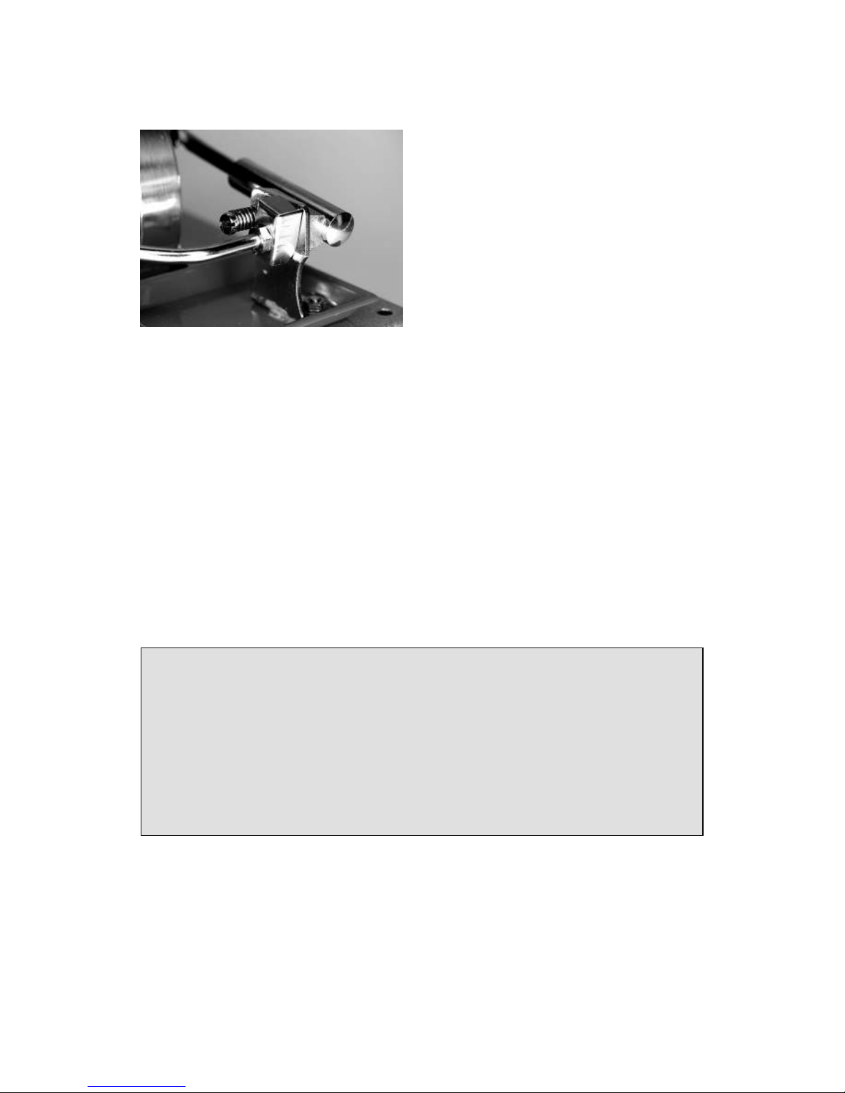
Note: To explore the effect of charge realistically, please discharge the
electrolytic before each experiment. Attention: the discharge might create
a harmless sparkle.
Fig.3.44: Before the experiments discharge the electrolytic with a
screwdriver
Page 62

62
Assembly of the experiment: generator, bread board, one red and one black
cable with crocodile clips, orange LED, series resistor 1 K-Ohm (red, black,
brown, gold), 2x electrolytic 4700µF
Fig.3.45: a) circuit of charge and b) with one electrolytic and LEDs as
charge- respectively consumption indicator
Steps of the experiment:
Mount the circuit according to the figure, circuit diagram. Plug one
electrolytic into the bread board (the positive pole is especially marked) and
charge it through the generator for a couple of seconds while the steam
engine is running.
Additional experiment: slow down and stop the fly wheel of the steam
engine shortly, and then let it run again. The orange LED flashes while the
generator works, it goes of when stopping the fly wheel.
Additional experiment: take away one crocodile clip from the bread board;
the current to the generator is now disconnected. Still the LED continues to
shine.
Fig.3.46: circuit diagram of
the electronics of charge
Page 63

63
Fig.3.47: circuit of charge
with two electrolytic and
one LED as charge- and
consumption indicator
One can repeat those experiments, this time with an additional electrolytic
plugged in parallel. The steam engine charges simultaneously both
electrolytic through the generator.
Fig.3.48: circuit
diagram with 2
electrolytic and one
LED as a chargeand consumption
indicator
In both experiments you can observe that the energy storage does not keep
the charge, when the steam engine or the generator is shortly stopped. Still
the Led continues to shine for a short while, when the generator is
disconnected from the bread board (one crocodile clip).
Is there a leak or what is happening?
With this charging system the electrolytic is discharging backwards into the
generator. Here it is not possible to store the energy efficiently and
continuously. We do need an electrical valve, which allows the current to
flow only in one direction and stop it in the other one, to avoid the
discharge. With this valve the electricity flows into the storage and does not
discharge unwanted.
Page 64

64
3.8.2 Diode blocking discharge, Schottkydiode
Components: like before, additional one Schottkydiode BAT 48
As you could observe in the former experiments, the stored energy of the
electrolytic is discharged backwards into the generator. It is important to
install a blockage for the current not to flow backwards, like a diode when
charging an energy storage f. ex. the use of an electrolytic, Gold-Caps or a
battery. The diode works like a valve which allows the current to flow in
forward direction, whereas in the reverse direction the current flow is
blocked.
With siliceous diodes the current starts flowing with a voltage from ca 0,6
till 0,7V or 700mV (mini Volt). A Schottkydiode allows the current to flow
already with 0,25V.
Note: blockage - diodes avoid the discharging of the storage. Normal
siliceous diodes “destroy” about 0,6V of the generated voltage;
Schottkydiodes only 0,25V.
Using a charge system we have to take the loss of energy into account
because here minimal voltages are important. Depending on the type of
diode we use, an amount of 0,6V to 0,25V will get lost and not be stored. In
the following experiment we can recognize that less voltage is charging the
electrolytic, because an additional diode is connected. Especially when the
voltage of charging is relatively low, it is easy to observe.
Page 65

65
Fig.3.49: Assembly of the experiment, b) detail: mounting of the diode, the
black ring (cathode) is on the left side of the picture
This experiment shows that the electrolytic is charged by the generator, is
keeping the voltage and storing it.
Fig.3.50: circuit diagram: discharge protection diode
You can measure the voltage which is stored in the electrolytic with a
multimeter. Switch the multimeter onto the direct current measuring area
(DC,20V).and connect the cables of the multimeter with the connection
wires of the electrolytic according to the polarity.
Page 66

66
Fig.3.51: Measuring
the voltage with a
multimeter, you can
see the cables of the
multimeter (in the
lower part of the
picture on the left)
connected to the
electrolytic connection
cable.
The following questions come up while charging the storage: is he empty,
half full or full? If you have a multimeter you easily can find out by
measuring the voltage of the input. The next experiment shows a simple
electronic indicator, using a flashing LED.
In the next part you see the construction of a simple charge indicator, which
shows the state of charge of the electrolytic through the voltage indicator.
3.8.3 Charge indicator for the electrolytic
Assembly of the experiment: components like before, additional one more
series resistor 1 K-Ohm (red, black, brown, gold), 1 red flash LED
Mount the circuit by plugging the components into the bread board
according to the figure. In the upper part of the bread board the electrolytic,
the positive pole to the right and in the same line the connection wire of the
diode (cathode, with a mark on the enclosing) and a jumper to the switch. In
the lower part the series resistor, the flash LED and the orange LED (the
longer connection wire to the right side).
Page 67

67
Fig.3.52: Charge indicator with the
flash LED, assembly of the circuit
on the bread board
Fig.3.53: circuit diagram of the charge indicator
Please make sure that the electrolytic is empty before starting the
experiment; f. ex. join both connection cables of the electrolytic through a
screwdriver.
Now prepare the steam engine according to the instructions in chapter 2.4.
The pulley wheel of the generator and the steam engine are connected with
the transmission belt.
Start the steam engine and wait till the fly wheel is running properly. Then
connect the crocodile clips which are connected to the generator with the
pins on the bread board. One can observe after a couple of minutes that the
red flash LED first flashes weakly and then becomes stronger and stronger.
The weak flashing of the red flash LED shows a voltage of ca. 1,7V, the
bright flashing around 2,5V.
flash LED
Page 68

68
With this assembly and the running steam engine you can continue to
explore more experiments, like f. ex.:
Disconnect for a short time the red crocodile clip next to the diode
from the pin, wait and then connect again.
Plug in another electrolytic 4700µF parallel to the first one. The
LED stops flashing shortly after the electrolytic has been plugged
in. After a while the LED flashes again. The reason is that the
additional electrolytic first needed to be charged.
Fig.3.54: plug in an additional
electrolytic, underneath of the
second electrolytic we find the
series resistor of the flash LED,
in the lower part of the picture
on the left side
Fig.3.55: circuit diagram with charge indicator and two electrolytic
flash LED
Page 69

69
3.8.4 Using stored energy
Assembly of the experiment: the circuit of the former experiment will be
slightly changed. Take out the LEDs and the series resistors, plug in the pin
of the positive pole on the very right of the bread board and put in the
schottkydiode so that she is parallel connected to the switch. Now it is
possible to bridge the schottkydiode by pressing the switch and to connect
the electrolytic directly to the generator.
Fig.3.56: circuit of the storage on the bread board, b) detail, in the picture
the diode with the cathode (ring on the enclosing) is turned to the left
After sufficient time of charging, slow down the fly wheel, take of the belt
and press the switch. Now you bridge the diode. The stored energy flows
out of the electrolytic into the electrical machine, which works like an
engine now. The axis of the engine turns for a short while.
Fig.3.57: circuit diagram
with the switch to bridge
the blockage diode
Page 70

70
Fig.3.58: measuring the voltage of the electrolytic with a multimeter
3.8.5 The steam engine as a charging station for the torch.
Assembly of the experiment: we use the assembly of the second last
experiment. We plug in two white LEDs instead of the orange LED.
You can disconnect the crocodile clips after a short charging period through
the steam engine and generator.
Now both LEDs will shine for a while when you press the switch. Then you
can connect the bread board with the “LED torch” to the charging station
“steam engine” again.
It is amazing how long the LEDs are shining with this charge regarding to
the small storage capacity of the electrolytic.
Page 71

71
Fig.3.59:
Charging
station, LED
with the
steam
engine
model
Fig.3.60: Assembly of the
bread board, with two
parallel plugged in
electrolytic 4700µF,
Schottkydiode, switch, two
white LEDs and jumpers`
Page 72

72
Fig.3.61: circuit diagram of the charging station
Fig.3.62: disconnected
“LED torch” in action
One can create a lot more experiments with the Steam Box D 100E and with
the E-Box 50.
I wish you a lot of fun and creativity!
D5
LED whiteD4LED white
Page 73

73
4. Annex
4.1 Collection of the formularies
Here you find some formularies for basic circuits we have been applying
and exploring in the experiments.
4.1.1 Voltage, current and resistance
The most important values of the electronic technique are voltage, current
and resistance, gathered in the law of Ohm with the following symbols and
values.
symbol
unit
voltage
U
V
current
I
A
resistance
R
Ω
The flowing current is increased within a circuit when the given voltage of
an electric circuit is increased. The power of current (I) is proportional to
the given voltage.
The flowing current diminishes when the resistance is raised along with a
constant voltage. This process is used f. ex. in the alimentation of the LEDs
with electricity. The current “I” behaves opposite proportional to the
resistance “R”.
With the following formularies you can work out the three values:
Current = voltage/resistance; or as a formulary:
Example:
Voltage U = 3V
Resistance R = 100 Ohm
Calculated current I = 3V/100 Ohm = 0,03A or 30mA
We can develop the following formularies from here:
Voltage = resistance x current; or as a formulary:
Page 74

74
And resistance = voltage/ current; or as a formulary:
4.1.2 Parallel circuit of resistors
When connecting two resistors R1 and R2 parallel the following total
resistance R results:
R = (R1 x R2) / (R1 + R2)
Example:
Resistance R1 = 1 k-Ohm parallel to the resistor R2 = 100 Ohm
Calculated total resistance R = (1 x 100) / (1 + 0,1) = 99,9 Ohm
The total resistance becomes less.
Another example shows when two similar resistors of 1 k-Ohm are parallel
connected:
(1 x 1) / (1 + 1) = 0,5 k-Ohm
The total resistance is reduced to a half
Fig.4.01: parallel circuits of resistors
R = total
Page 75

75
4.1.3 Series connection of resistors
When you connect resistors one after the other in a row, you add the values
of R1 and R2 to the total resistance: R = R1 + R2
Example:
Resistance R1 = 100 Ohm and resistance R2 = 1 k-Ohm
Calculated total resistance: R = 100 Ohm + 1 k-Ohm = 1100 Ohm
Fig.4.02 series connection of two
resistors
4.1.4 Calculation of the power
You can use the following formulary to calculate the electric power:
P = U x I (P=electric power, U=voltage, I= current)
“P” is measured in Watt, “U” in Volt and “I” in Ampere.
Example of a calculation:
A direct current generator generates a voltage of 3,0 Volt and provide a
current output of 50mA.
3,0V x 0,5mA has a power of 0,015Watt.
4.2 Troubleshooting
Here you find some tips and hints in case the steam engine does not run
properly or the electronic does not function at all or is unstable.
R = total
Page 76

76
4.2.1 The steam engine
In general the smoothness and the leak tightness of a steam engine model do
not influence the basic function. Never the less it is important that the steam
engine runs easy and smooth. For all models and as well for the steam
engine model counts: the smoother they run the better they function.
A small steam engine model is not able to run with its full power when the
belt of the fly wheel towards the generator is too tight. The generator needs
at least 1000 rotations/min coming from the steam engine, to generate
sufficient voltage, to make the LEDs flash.
The power is also depending on the leak tightness. Make sure that the seals
are fitting well between the boiler, the steam tubes and the cylinder and that
the connections are properly tightened and no steam is escaping.
Please adjust the timing if the valve - controlled steam engine does not work
properly. Use the instruction and the figure to set the timing.
4.2.2 The electronic
Please pay attention to the following points when a circuit on the bread
board does not function properly:
When nothing happens after mounting the circuit do not get
nervous and prove the current coming from the generator. Are all
connections plugged in well? Sometimes the connection cable of
the generator is not properly connected to the crocodile clip.
Does the steam engine have enough rotational speed? One can use
a multimeter or mount a simple circuit with one red LED to prove
the generated voltage of the generator. You can connect the LED
straight away to the crocodile clips for a short while; the red clip to
the longer wire of the LED.
Now prove the components of the mounting of the circuit. Are the
polarities (positive and negative pole) correct? Is there a part
which is not plugged in properly?
Are all parts plugged in with the right polarity, f. ex. the LEDs?
The longer connection wire is the positive pole.
The longer connection wire of the electrolytic is also the positive
pole and additionally you find a minus symbol on the enclosing of
the negative pole.
Page 77

77
Does the circuit work but the results are not satisfactory?
Please ask yourself first whether this steam engine model can
generate sufficient power?
If you have not found any mistake so far and the steam engine is
running full power, please control the circuit and all connections,
starting from the generator to the electrolytic and to the rest of all
components. May be one part is still missing?
4.3 Supplier sources for spare parts and electronic parts
Consumables (see below and others) and spare parts for steam engines are
available through Wilesco distributors or: www.sell-it-easy.de (info@sellit-easy.de).
Electronic parts are available for example with www.conrad.de
4.3.1 Consumables for steam engines
Designation
Content
Item-no.
Driving belt, 260mm long Z80
1 package = 5 spirals
00800
Dry-spirit tablets Z81
1 package = 20 tablets
01020
Steam engine oil Z83
1 Plastic bottle 30ccm
00801
Accessory bag „electronic parts“
divers electronic parts
01459
Generator holder
1 piece
01460
Generator with mounting support
1 piece
01461
Page 78

78
4.4 Warranty:
All WILESCO Steam Engines are carefully checked before leaving the
factory. However if a problem arises, you can return the Steam Engine to a
specialized distributor or directly to WILESCO. We are sure you will
understand that already fired or used models cannot be exchanged for new
ones. The most frequent claims are leaking boilers. The solder will be
destroyed if your Steam Engine runs without enough water in the boiler. In
such cases, the solder liquefy drop-shaped and the boiler leaks. This is an
obvious proof that the boiler was fired without enough water. Please watch
always carefully the water level, because the heating without enough water
excludes any demand for warranty.
This Steam Engine is only designed for the above described function.
Technical data can be amended without prior notice.
WILESCO wishes you lots of fun with your steam engine and
„full steam ahead“!
Wilhelm Schröder GmbH & Co. KG
D-58511 LÜDENSCHEID Schützenstraße 12
phone : +49 - 2351 - 9847-0 e-mail : info@wilesco.de
Page 79

79
The qualified internetshop -
The classic
steam roller D365
The complete Wilesco range on stock
Steam engine D21
Dry-spirit tablets
Z81
Sell-it-easy IH GmbH
Schützenstraße 12
D-58511 Lüdenscheid
Germany
phone: +49 2351-984780
fax: +49 2351-984781
info@sell-it-easy.de
www.sell-it-easy.de
 Loading...