

Page 1
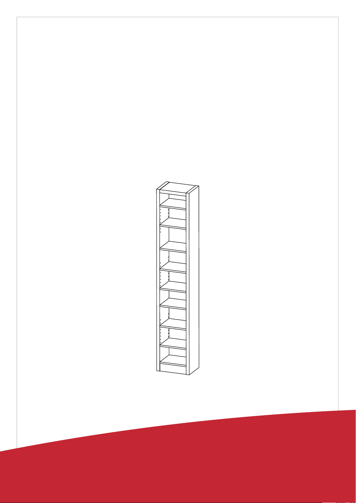
Fine Furniture for every stage of life
ASSEMBLY INSTRUCTIONS
Page 2
ASSEMBLY INSTRUCTIONS
ASSEMBLY TIME
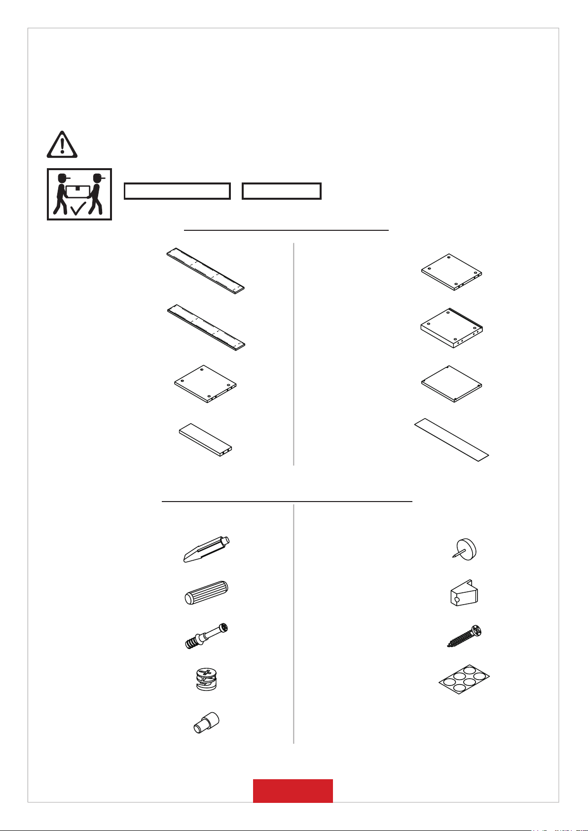
PARTS IDENTIFICATION
30 MINUTES
ASSEMBLY TIPS:
1. Remove hardware from box and sort by size.
2. Please check to see that all hardware and parts are present prior to start of assembly.
3. Please follow attached instructions in the same sequence as numbered to assure fast & easy assembly.
WARNING!
1. Don’t attempt to repair or modify parts that are broken or defective. Please contact the store immediately.
2. This product is for home use only and not intended for commercial establishments.
NOTE:
Phillips head screw driver is required in the assembly process; however, manufacturer does not provide this item.
A
B
C BOTTO M PANE L
D CROSS BR ACE
Z
NO DESCRIPTION FIGURE Q’TY
LEFT SIDE
PAN EL
RIGHT SIDE
PAN EL
HARDWARE IDENTIFICATION
1 PC
1 PC
1 PC
1 PC
E CROSS PANEL 2 PCS
F TOP PAN EL
ADJUSTABLE
G
H BACK PANEL
NO DESCRIPTION FIGURE Q’TY
PAN EL
1 PC
6 PCS
1 PC
1 GLUE 15g
WOODEN DOWEL
2
3
4
5
Ø 8x30mm
CA M BOLT
Ø 7x35.5mm
CAM LOCK
Ø 15x12mm
PIN
Ø 4.9x8mm
1 PC
20 PCS
16 PCS
16 PCS
24 PCS
PAGE 2 OF 7
6
7 FIXER
8
9
PLASTIC FEET
Ø 15m m
SCREW
Ø 3x19mm
STICKER
Ø 20mm
4 PCS
4 PCS
4 PCS
3 PCS
Page 3
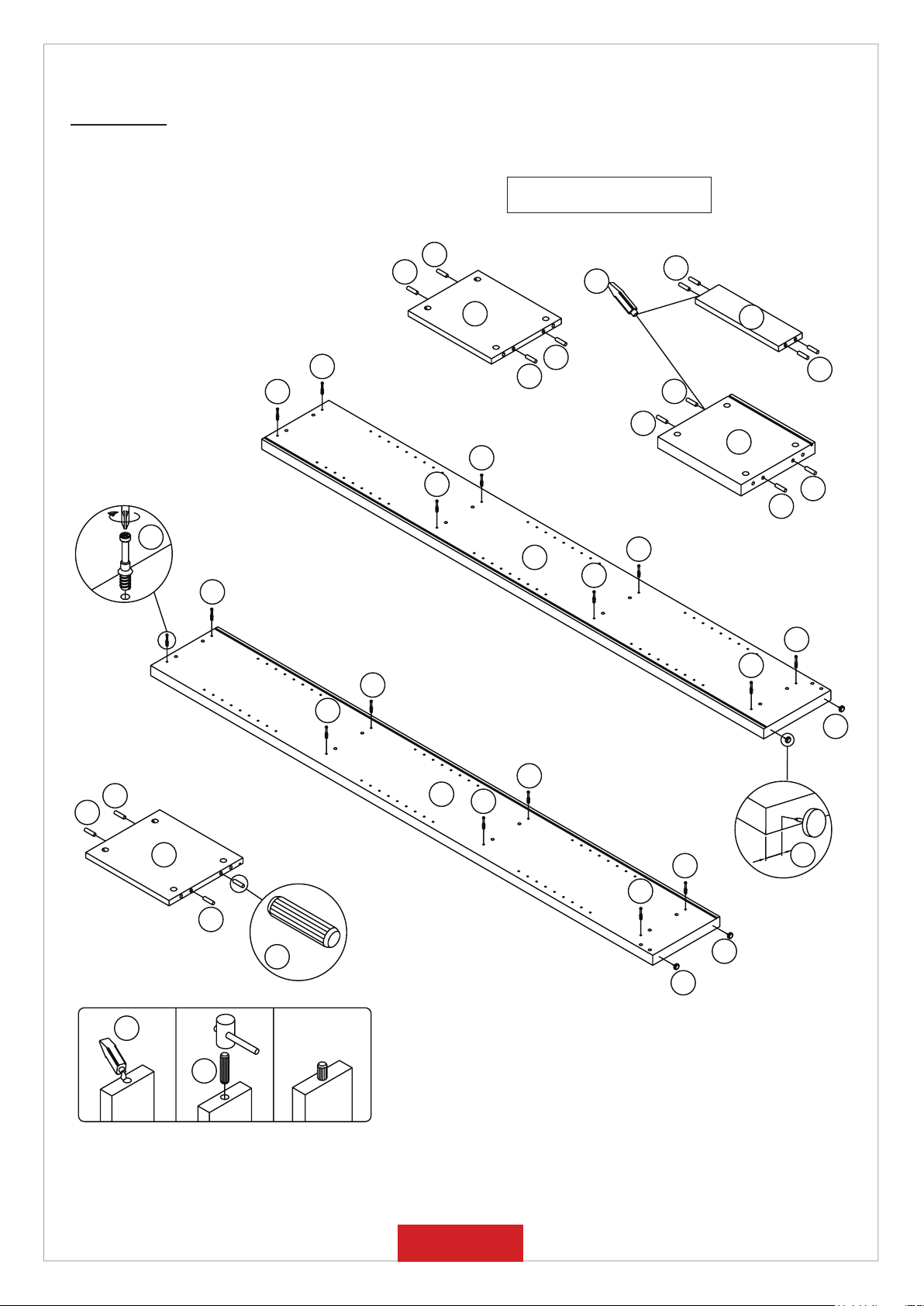
STEP 1
Apply glue on all wooden dowels to
ensure integrity of the structure.
3 x16
2
2
1
E x2
3
2
2
3
2
D
2
2
2
F
3
3
2
2
B
3
3
3
3
3
3
3
6
3
2
2
C
A
3
1"
3
6 x4
3
2
2 x20
6
6
1
2
PAGE 3 OF 7
Page 4
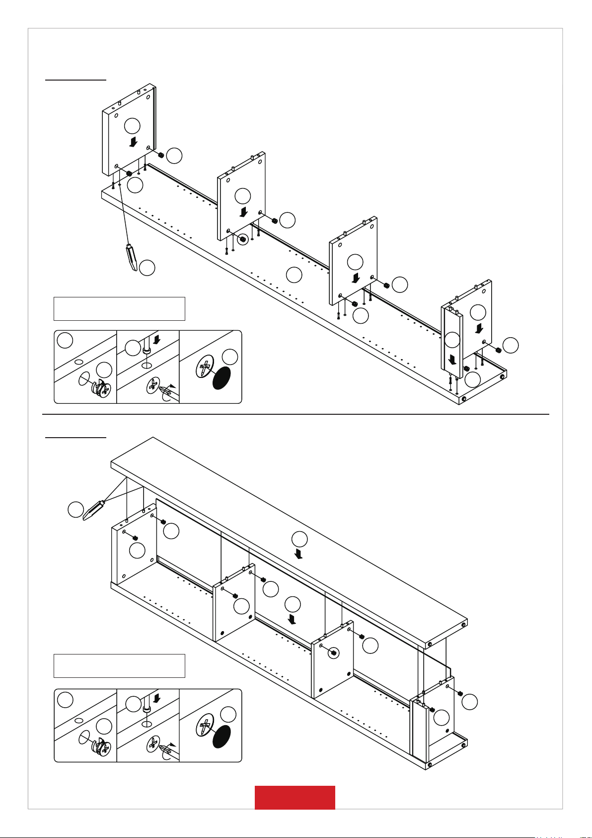
STEP 2
F
4
4
E
4
1
Apply glue on all wooden dowels to
ensure integrity of the structure.
4 x8
3
4
STEP 3
1
4
E
A
4
D
C
4
4
9
4
4
B
Apply glue on all wooden dowels to
ensure integrity of the structure.
4 x8
3
4
4
4
H
4
4
9
PAGE 4 OF 7
4
Page 5
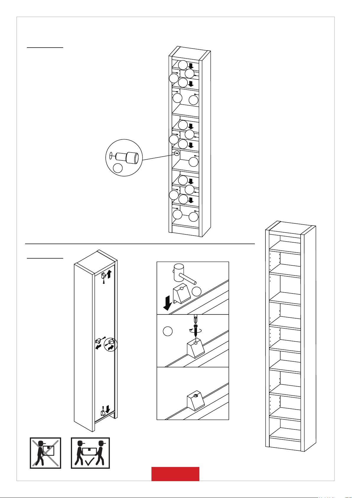
STEP 4
5 x24
G
5
5
G
5
5
G
5
5
G
5
G
5
5
G
STEP 5
5
8 x4
COMPLETE
5
7 x4
PAGE 5 OF 7
Page 6
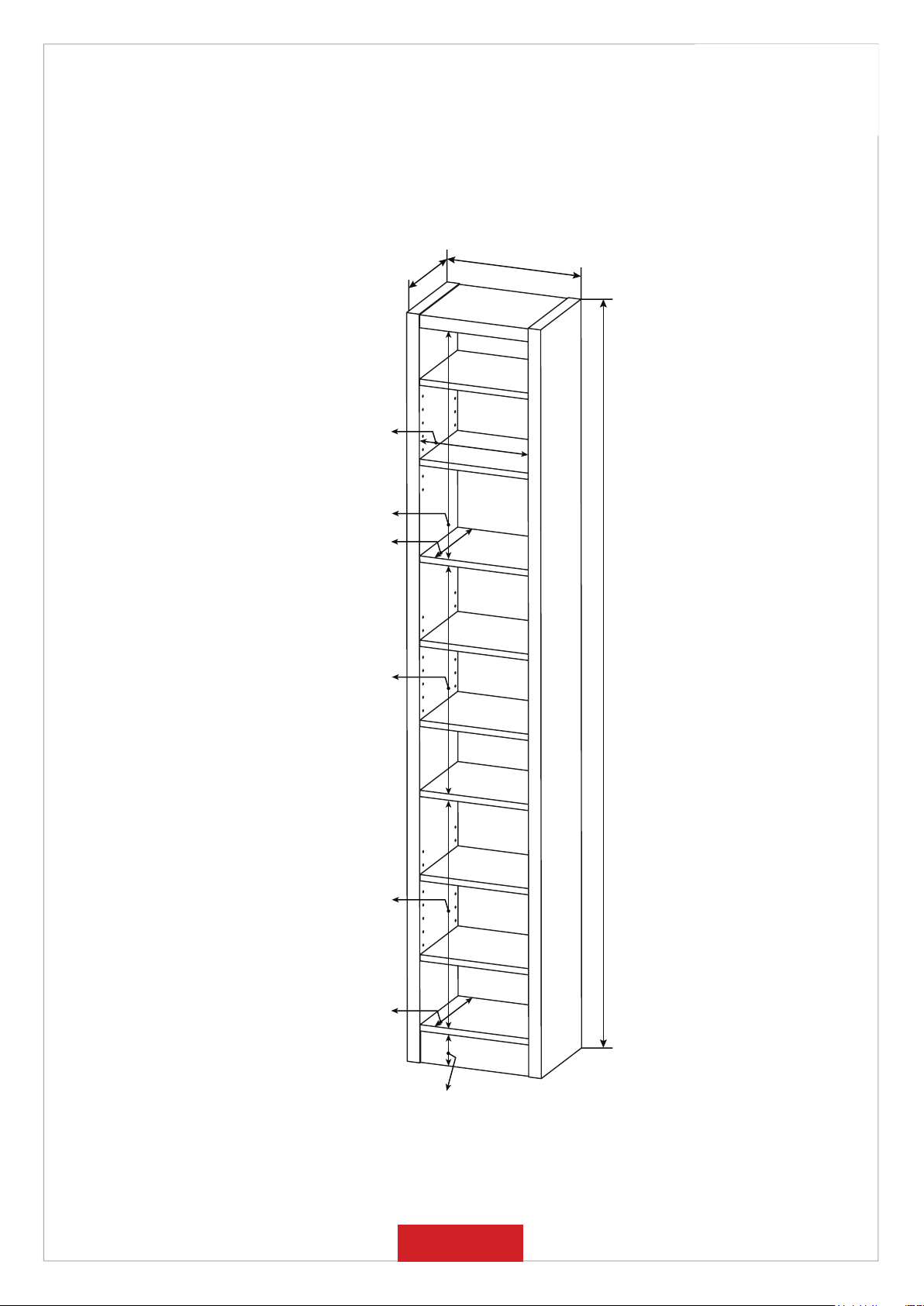
240mm(9.5")
268mm(10.55")
547mm(21.53")
225mm(8.86")
330mm(13")
547mm(21.53")
547mm(21.53")
227mm(8.94")
1800mm(70.75")
81mm(3.19")
Note : Dimension tolerance ±5%
PAGE 6 OF 7
Page 7
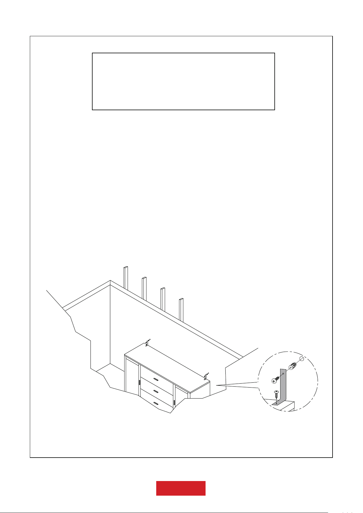
ANTI-TIPPING INSTALLMENT INSTRUCTIONS
FURNITURE TIPPING RESTRAINT
WARNING
Injury may result from tipping furniture.
This restraint may protect against tipping furniture.
Do not allow children to climb on furniture.
This restraint is not a substitute for proper adult supervision.
Failure to detach this restraint before moving the furniture
may result in injury and damage.
1. To attach the anti-tip strap, securely mount one end to the top of the case piece with
the 5/8” screw.
2. Position the case piece against the wall in the desired location.
3. Pull the anti-tip strap taut and mark the position of where you will secure the other end
on the wall.
4. Drill a 1-1/4” hole in the spot you marked.
5. Tap in plastic wall plug.
6. Fasten anti-tip strap with wall screw provided.
(Please install the anti-tiping kit in the middle of the case piece if only have one set of anti-tipping kit.)
WALL
PAGE 7 OF 7
 Loading...