

OPERATING INSTRUCTIONS FOR THE TRX-2000S RECEIVER
Important Precautions: Please read all instructions before usage.
DO NOT EXPOSE TO WATER, FIRE or EXCESSIVE DUST. Aluminum box is water
resistant; interior is NOT GUARANTEED WATERPROOF. In rain or fog, close lid, wrap
in plastic or use from inside vehicle.
When the DC external power cord is used, ALWAYS insert the cord's plug into the
receiver's DC external power jack BEFORE plugging the cigarette lighter cord into
a vehicle. Failure to follow this procedure can cause the fuse in the cigarette lighter
power plug to blow.
After batteries have been used for 5 hours, they should be charged for 4 hours for each
hour of operation. Do not charge more than 24 hours. Overcharging can result in
loss of battery life.
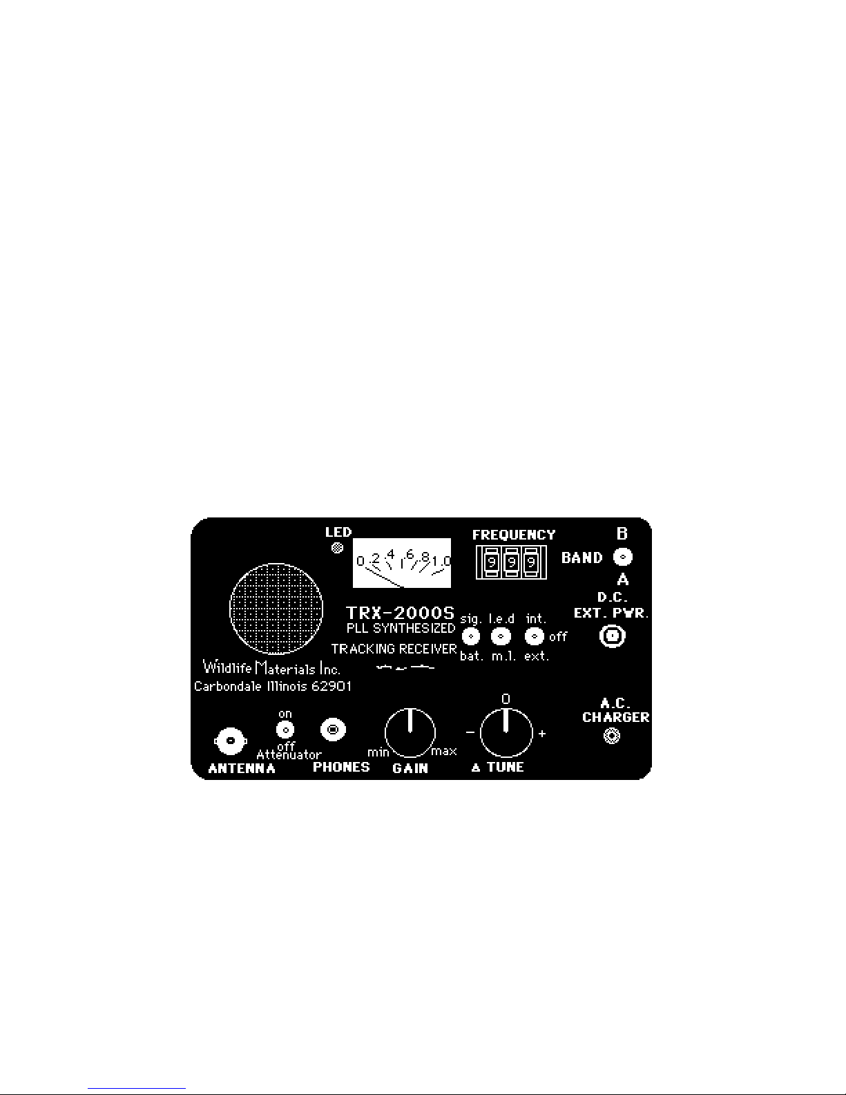
INFORMATION about CONTROLS:
ANTENNA JACK: Accepts any 50 ohm coaxial cable with a BNC plug. To insert plug,
push in jack and give a slight twist to the right.
ATTENUATOR Switch: Prevents swamping of the received signal at close range. When
the transmitter-wearer's signal seems to come to the receiver with equal strength from
all directions, an attenuator can make the true direction easier to find. Turn Attenuator
switch ON. The strongest signal will come from one direction, where the animal is
located. When not needed, (if transmittered animal moves farther out) turn attenuator
switch OFF.

PHONE JACK: Allows use of monaural headphones or earphones with 1/8-inch (3.5
mm.) plug.
GAIN: Varies the sensitivity of the receiver. Lowest gain is obtained by turning the
control to the left; highest gain is achieved by turning the control to the right.
∆ (DELTA) TUNE: Makes fine adjustments in the receiver frequency in order to give the
most pleasant tone to the transmission being received. When the knob pointer faces up
or is centered, the receiver will be tuned to the exact frequency indicated by the
frequency switches (located to the right of the signal meter). When the knob pointer is
turned to the left, it tunes in a slightly lower frequency; when turned to the right, the
receiver is tuned slightly higher in frequency than frequency switches indicate.
SIG/BAT TOGGLE SWITCH: Causes the meter to indicate either the signal strength of
a transmission being received or a low battery in the receiver. Normally, a charged
battery will register 6 or 7 on the meter. If the meter falls below 6, the battery requires
recharging.
LED/ML TOGGLE SWITCH: Allows user to select either the meter light for night
tracking or the flashing LED circuit (located at the upper left of the meter) which gives
off an intensity proportional to the strength of the incoming signal. A center-off position
allows the user to save battery drain during daytime.
INT/EXT TOGGLE SWITCH: Chooses the means of powering the receiver--either the
internal receiver battery or the external DC power source. When the receiver is not in
use, the switch should be left in the center-off position.
Signal METER: Serves the dual purpose of registering a low battery or relative signal
strength. The previously mentioned SIG/BAT toggle switch selects the information
desired.
FREQUENCY SELECT SWITCHES (3): Identify the frequency to be used by the
transmitter. Small pushbuttons, marked with "+" or "-", will change the number in the
window of each switch until the last three numbers of the transmitter frequency are
selected. EXAMPLE: If a transmitter frequency label is marked 217.137, then 137 will
be selected by pushing the switches. The ∆ TUNE control might require adjusting to
give the most pleasant tone to the transmission. NOTE: The last digit (right hand
switch) may need to be moved up or down one digit, when temperature variations or
other factors intervene, to allow for easy adjustment of the ∆ TUNE near the middle of
its range.
BAND SELECTION TOGGLE SWITCH: Located at upper right, this switch allows user
to choose which band (of two choices) to receive a signal on. Band A, beneath switch,
will always bring in the lower frequency band of the two available. Band B, above the
toggle switch, will bring in the higher frequency band programmed to the receiver.
DC EXT POWER JACK: Allows receiver to be powered by a DC power cord with
cigarette lighter plug-in.

AC CHARGER: Allows receiver's NiCad battery to be charged from a standard 110-120
VAC power source. NOTE: Charger should be left on 12 to 16 hours but never more
than 24 hours. Overcharging will shorten battery life.
AC CHARGE CORD and DC EXTERNAL POWER CORD: Included as accessories. A
leather carrying case is optional (Part No. 1000S-CC).
Operating Instructions:
1. Turn the POWER SWITCH to INT for internal battery usage, or to EXT for
external power source. If the DC external power cord will be used, insert the cord's plug
into the receiver's DC external power jack BEFORE plugging the cord's cigarette lighter
end into a vehicle.
2. Preset GAIN control to "12:00 o'clock" position.
3. Preset ∆ TUNE to 0 position.
4. Choose Band A (the lower frequency programmed to receiver) or Band B (the
higher frequency). Example: If you ordered a receiver with the 216 and 219 ranges, the
receiver will tune in 216 when you choose Band A and will tune in 219 signals when you
move the toggle switch up to Band B. The receiver operator can go back and forth
between frequency bands as needed.
5. Dial desired frequency on the 3 FREQUENCY SWITCHES. Push the small
buttons marked with "+" or "-" until numbers represent the last 3 digits in the transmitter
frequency. EXAMPLE: A transmitter marked 217.650 would require the switch
numbers to register 650.
6. Attach antenna cable to ANTENNA JACK by pushing the BNC plug down and
twisting slightly to the right until it clicks into place.
7. Activate transmitter now.
8. ∆ TUNE control can now be adjusted to give the most pleasant tone/pitch from
receiver. Each time you change frequencies (shift from lower frequency range on
Band A to higher frequency range on Band B and vice versa) you will need to adjust
the ∆∆∆∆ Tune control for best tone.
9. Advance the GAIN control slowly in clockwise motion as far as necessary to
receive a clear signal.
10. If the signal sounds loud or distorted, turn the GAIN control counterclockwise
until the signal is clear and acceptable in volume.
11. If the ∆ TUNE control cannot bring in the signal clearly and with a pleasant pitch,
the last FREQUENCY SWITCH on the right can be moved up or down 1 or 2 digits to
bring the tuning within the range of the ∆ TUNE control. If the right switch is already at
an extreme, e.g. 0 or 9, the middle digit can be readjusted up or down one number.

EXAMPLE: If a user dialed 139 on the receiver, turned the ∆ TUNE control all the way
toward "+" or to the right, and found that the tone from the speaker was still not quite
acceptable, he/she could dial 140 or 141 and readjust the ∆ TUNE control back toward
0 again. Or, if a user dialed 100 on the receiver and the ∆ TUNE control was turned all
the way toward "-" (left), and the tone was still not acceptable, he/she might try dialing
098 or 099. Then readjust the ∆ TUNE control back toward 0.
12. To use the SIGNAL METER, place the SIG/BAT toggle switch in the SIG
position. The meter will indicate relative signal strength. If the meter needle moves too
far to the right, turn the GAIN control to the left. If no signal meter indication is seen,
advance the GAIN to the right.
13. To determine strength of the receiver battery, place the SIG/BAT toggle switch in
the BAT position. A charged battery will register 6 or more on the meter. If the meter
falls below 6, the receiver battery requires recharging. See recharge directions in #18
below.
14. For night use, the ML/LED toggle switch can select either the meter light or a
flashing LED circuit. Both the signal meter and the LED can be adjusted by using the
GAIN control to compensate for weaker or stronger transmitter signals. NOTE: During
daylight hours, keep the ML/LED switch in the center-off position to conserve the
battery.
15. To prevent swamping of the received signal at close range, turn Attenuator
switch on. If your animal's signal comes at the receiver equally from all directions, you
are very close. Turn Attenuator switch on so that the strongest signal will come from
one direction, where animal is located.
16. To use headphones, turn the GAIN control all the way to the left, plug in
headphones, and adjust GAIN for comfortable volume level.
17. To use the DC EXTERNAL POWER CORD, insert the cord's plug into the
receiver's DC EXT POWER jack BEFORE plugging the cord's fused cigarette lighter
plug into a vehicle. Then move the INT/EXT power switch to EXT to use the external
power source.
18. The receiver's nickel cadmium batteries give 5 to 6 hours of tracking between
charges. Before charging, place the power switch on OFF. To charge the receiver,
insert the AC CHARGER CORD plug into the AC CHARGER JACK. Then plug the
other end of the AC CHARGER CORD into a 110-120 VAC, 60-hertz power source
(house current). To fully charge a battery, charge for at least 16 hours and never more
than 24 hours. Overcharging may shorten battery life. After your receiver is fully
charged, it should be charged 4 hours for every one hour of operation. Again, never
recharge for more than 24 hours.
19. Vary your recharge times to avoid a "memory" buildup. If you recharge 4 hours
each time, the battery will gradually become good for only 4 hours of life. Avoid a
recharging pattern to get the most out of a battery. For instance, if you charge for 4

hours one time, use your equipment until a charge of 8-10 hours or 12-14 hours or 1620 hours is required the next time.
20. During storage periods, the receiver should be turned on every 3 to 4 months
and allowed to run for 2 to 3 hours. Then recharge for 12-16 hours before putting the
receiver back on the shelf. When you are ready to track your dog again and if the
receiver has not been used for some time, be sure to recharge the unit.
21. Store in a cool dry place.
The TRX-2000S Receiver has a FIVE YEAR warranty on ELECTRONICS.
TROUBLESHOOTING the TRX-2000S RECEIVER
Please check the following list before you return the TRX-2000S Receiver to WMI for
repairs.
I. If you turn the TRX on and it doesn't work:
A. Turn INT./EXT switch to INTernal power.
B. Turn BAT/SlG switch to BATtery.
C. If meter needle registers 6-7, the battery is OK.
D. If meter needle registers below 6, the battery is probably discharged.
1. Charge battery for 1 hour and recheck. The receiver may now be OK.
2. If the battery does not charge, check the voltage output of the recharge
unit on a DC voltmeter. If the recharger fails to register in the normal 12-18
v range, a new recharger is needed. Return receiver with recharger to
WMI; include note on tests run. During warranty period, old recharger
must be returned before new recharger is shipped.
E. If the battery won't charge and the recharger tests OK, send the receiver back
to WMI. Include note on behavior and tests run.
F. If the battery tests OK, charge receiver 18-20 hours before use. Then try to
tune in the frequency no. of a collar.
1. Turn GAIN Control fully clockwise. Do you get a sound? You may need
to place your ear by the speaker. If you get no sound, send receiver and
recharger to WMI with note on behavior and tests run.
II. If you hear a signal, is it a) a musical beep or b) a dull thump?
A. If you hear a) a musical beep; attach your antenna cable to receiver. Check
range of at least 2 transmitter collars known to be good. During test, place
good transmitters on stump, box, or block about 6-12 inches above ground. Do
you get a normal signal range for the collar type used? If not, send receiver and
antenna back to WMI with a note on tests run.
B. If you hear b) only a dull thump,

1. Tune the frequency number up and down several numbers or KHz to
see if the frequency has shifted. i.e., if your collar frequency number is
212, go from 213 to 214 to 215; then go down to 211, 210, 209 to see if a
signal comes in. It is not unusual for the collar's frequency number to
come in on the receiver at a different number, or to slip by 1 to 3 KHz up
or down. However, larger frequency shifts of 5 to 10 KHz are uncommon
and unacceptable.
2. Borrow a buddy's working receiver to see if your transmitter collar's
signal will come in at the correct frequency number on another receiver.
This will insure that the collar is not the problem.
III. If the receiver is not getting the range you expect:
A. Is the problem the same with all your collars? If you have only one collar, try a
buddy's that is on the same frequency.
B. If all your collars are giving poor signal range, borrow an antenna and cable
that work. Try picking up each collar signal with the borrowed antenna and cable.
1. If the collar signals come in well, you probably need a new antenna
cable. Or, less likely, the antenna needs repairs.
2. If all collar signals do not come in well with a borrowed antenna and
cable, send the receiver, recharger and collars back for repair. Include
note on equipment behavior and tests run.
IV. If the transmitter collar signal does not come in on the frequency assigned to
it:
A. Check your other transmitter collars on your receiver. Are they off frequency
also?
1. Tune the frequency number up and down several numbers or KHz to
see if the frequency has shifted. For example, if your collar frequency
number is 217.212, go up to 213 to 214 to 215 on the frequency dial; then
go down to 211, 210, 209 to see if a signal comes in. It is not unusual for
the collar's frequency number to come in on the receiver at a different
number, or to slip by 1 to 3 KHz up or down. However, larger frequency
shifts of 5 to 10 KHz are uncommon and unacceptable.
2. Borrow a buddy's working receiver to see if your collar frequency
numbers come in. Insure that the collars are not the problem.
B. If all collars are off frequency, the receiver needs to be calibrated. Return
receiver and recharger to WMI.
V. If you get noise from the receiver, but no signal:
A. Does receiver fail to work when exposed to either very hot or cold or humid
conditions?
B. Allow the receiver to return to room temperature, then check.
C. If the receiver still doesn't work, return receiver and recharger to WMI with
note about temperature effects, if any.
VI. If the ∆∆∆∆ (Delta) Tune knob has slid or loosened on its shaft:

A. You will not be able to locate your dog's signal at its assigned frequency. To
center the Delta Tune knob,
1. Turn the Delta Tune and the Gain Control knobs down to low, with both
their white lines in matching positions.
2. Then tighten the screw at the side of the Delta Tune knob.
3. Return Gain knob to desired level.
4. Place Delta Tune line at 0 or center.
VII. If the Signal Meter Needle stays or "hangs" at the low end of the meter:
A. When the needle does not go down to 0, your readings will be off kilter. To
"zero the meter,"
1. TURN OFF POWER.
2. Place BAT/SIG switch on SIGnal.
3. With a small screwdriver, turn screw beneath signal meter until needle
centers on zero line.
VIII. If your receiver has gotten wet (by humidity, fog, rain, snow, dropping in pond,
etc.):
A. The signal meter needle sticks at the right side of the meter. The needle
stays up or "hangs" rather than coming down.
B. DO NOT OPERATE during this time. Turn power OFF.
C. Water damage may void your warranty.
D. If your receiver has been dampened by moisture:
1. Turn box upside down with lid open to form an inverted V.
2. Draw moisture out with a fan or blow dryer set on LOW. Dry by blowing
air through receiver from one end to another.
E. We prefer that you send the receiver to us immediately!
F. However, if water runs out of receiver when turned upside down, the circuit
boards have been drenched with water. It becomes important to minimize
damage as quickly as possible.
1. On receiver face, remove four corner screws, 2 from left side and 2
from right side. These screws are inside the rubber lip and nearest to the
lip. Use the screw just right of the AC Charger as guide.
2. Lift the entire receiver assembly from blue case. DO NOT TAKE THIS
ASSEMBLY APART! Leave 3 boards intact, with spacers between.
3. Disconnect the battery: pull apart white connector at right.
4. Turn on oven to 200 degrees, open door, and pull out bottom rack.
5. Put receiver assembly on rack so warm air will pass over it.
6. DO NOT PUT RECEIVER IN OVEN, even with door open.
7. After receiver assembly has dried, reassemble using new battery pack
($35.00). Receiver moisture usually harms battery, which then corrodes
and leaks onto circuit boards.
NOTE:

These recommended actions do not guarantee that the receiver will work when
reassembled. If the receiver works, there is no guarantee that it will continue to do so for
a long period of time. However, the above actions will slow down or minimize corrosion
of circuitry.
If the receiver works, the customer may continue to use the unit. However, we
recommend that the receiver be returned to WMI as soon as possible for inspection.
WHEN A RECEIVER IS OPENED, THE SENSITIVITY AND CALIBRATION MAY BE
ALTERED.
If the receiver does not work, send it back to us for a repair estimate. Please include all
receiver parts in your shipment. Also include your phone number and a written
message that explains any unusual behavior and your actions to stop the behavior.
This information will help the technician to go quickly to the problem, saving time and
repair costs.
TO CHANGE BATTERY PACK:
After your warranty has expired, a battery pack can be changed at home. (When
receiver is under warranty, we change the battery at our facility, then charge, retune, &
recalibrate to insure quality performance.)
INSTRUCTIONS:
1) Remove 4 screws (at left upper and lower edge of faceplate; at right upper and
lower edge of plate) from faceplate.
2) Lift only the faceplate off: grasp antenna jack and tilt right side of faceplate higher.
(DO NOT lift up the layers of circuit boards! The receiver is tightly packed with
components and you will have difficulty stuffing wires etc. back where they belong!
Shorted and burned wires can result.)
3) Battery pack is at right as you look into receiver. Unplug old battery pack. To get old
battery out, you may need to unscrew/loosen battery holder at right outside of box.
4) Plug new battery pack in, fit into battery holder and tighten outside screw as needed.
5) Fit faceplate on, lower left side first. Tighten screws at the four corners.
6) CHARGE BATTERY for 16 to 24 HOURS.
7) Test receiver; hopefully it will not need to be retuned or recalibrated.
VELCRO TO HOLD RECEIVER IN CASE
• With the receiver CASE, you’ll find two strips of unattached Velcro that have plastic
backing.
• Please look inside the case at the bottom and back center. You’ll find two
permanently attached Velcro strips.
• To protect your receiver, anchor the receiver to the case with Velcro.
--- Turn the receiver over. Peel the plastic backing off one loose strip. Place the strip at
bottom center of box. Rub to seal.

--- Turn the receiver so the back faces you. Peel the plastic backing off the other loose
Velcro strip. Place the strip at the back center of the receiver. Rub to seal.
• Fit the receiver in the case. The Velcro on the receiver and on the case will bond
together. This will insure that your receiver does not fall out during use.
Wildlife Materials, Inc. shall not be liable for any loss or damage resulting directly
or indirectly, or as a consequence of or incidental to, the use or loss of any
Wildlife Materials product including, without limitation, the original purchaser’s
expenses associated with downtime, interrupted or lost data, or damages to
persons, animals or property.
Wildlife Materials International, Inc.
1202 Walnut Street Murphysboro, IL 62966 USA
Phone: 1-800-842-4537
FAX: 618-687-3539
34 YEARS MANUFACTURING EXPERIENCE
 Loading...