

Wildlife computers Mote Installation Instruction

v.201901
[Type here] [Type here] [Type here]
Mote Installation Instruction
This user guide will give you all the essential information
needed for installing a Wildlife Computers Mote.

Table of Contents
Introduction ............................................................................................................................................................................ 3
Installation Tools Required ................................................................................................................................................ 4
Additional Equipment Required per Mote .................................................................................................................. 4
Mote Installation Instructions .......................................................................................................................................... 5
Off-Site Pre-Assembly and System Test ........................................................................................................................ 5
Tripod Assembly ................................................................................................................................................................... 5
Tripod Assembly for User-supplied Masts and Legs ................................................................................................ 6
Antenna Assembly ............................................................................................................................................................... 8
Enclosure Mounting.......................................................................................................................................................... 13
Solar Panel Mounting ....................................................................................................................................................... 15
Mote Wiring ......................................................................................................................................................................... 17
Power up the Mote ............................................................................................................................................................ 19
Protection against weather and pests ....................................................................................................................... 23
Troubleshooting................................................................................................................................................................. 24
Contacting Wildlife Computers .................................................................................................................................... 24
Page 2
The information contained in these documents is confidential, privileged and only for the information of the intended recipient and
may not be used, published or redistributed without the prior written consent of Wildlife Computers.
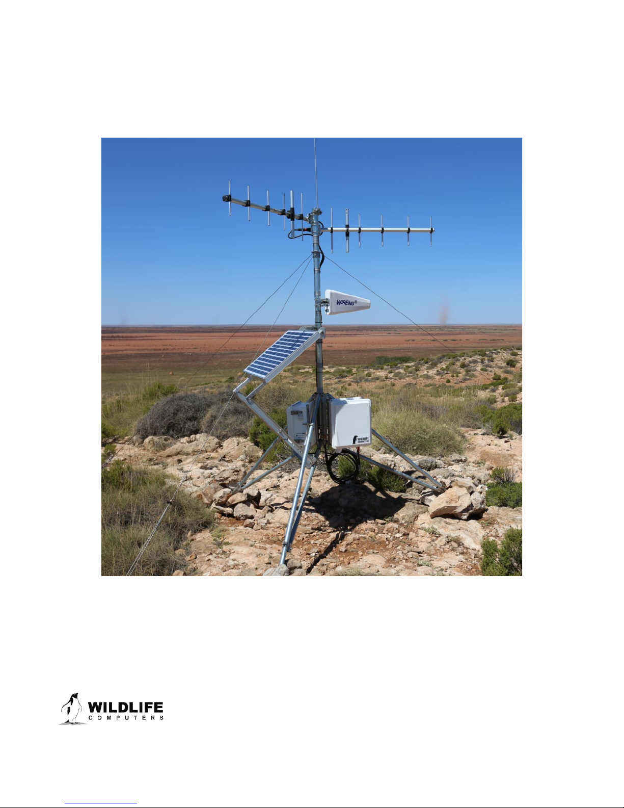
Introduction
This guide applies to any Mote sold by Wildlife Computers. Please note, your specific installation may
vary depending on your site or application.
Page 3
The information contained in these documents is confidential, privileged and only for the information of the intended recipient and
may not be used, published or redistributed without the prior written consent of Wildlife Computers.

Installation Tools Required
It is important to have all the tools you need for the installation. Here is a list of required tools to build
and complete your Mote installation:
• 1 x 7/16” open-ended wrench
• 1 x 1/2” open-ended wrench
• 1 socket set ratchet with 7/16”, 1/2” and 10mm deep sockets. (~2” deep)
• Battery drill/driver with 1/4” adaptor to take deep sockets—useful
• Battery drill and 3/8” drill bit to expand holes in the stake so it takes guy wire turnbuckles
• 7/16” and 1/2” ratchet wrenches—useful
• 8mm nut-driver or 6” adjustable spanner—for stay-wire adjustment nuts
• Zip ties, 12” or longer—25 needed per Mote
• Small 1/8” wide flat-blade screwdriver for the electrical connector blocks in the power supply
• 3/8” wide flat-blade screwdriver to tighten lightning rod and earth wires
• Large side-cutting pliers to cut up to 10 mm copper wire
• Box-cutter knife to cut tape and strip copper ground wire
• Small level for ensuring mast is vertical
• A satellite tag for testing to verify Mote operation
• A magnet to enable/disable the test tag
Additional Equipment Required per Mote
These items may be required depending on your site and which optional parts were selected. For
example, the pre-assembled tripod from Campbell includes spikes, a grounding rod, ground rod
clamp and grounding wire.
• 3-6-star pickets or metal stakes to anchor guy wires and possibly Mote feet into ground
• 2 padlocks to lock cabinets
• Moth balls, camphor sticks, or similar if insects are a likely problem
• Rubbing alcohol and rags to wipe down cables, and latex gloves to wear during installation—
see Campbell Scientific document regarding rodents
• Approximately 1/8” soft galvanized binding wire for anchoring guy wires to stakes
• Earth rod and wire clamp for earthing—standard residential 4’ or 5’ copper/steel earth rod and
clamp
• 3 m x 10 mm insulated cable for earth wire
• 2 rolls of 3M Super88 or similar high-quality electrical PVC tape
• Sledgehammer to insert metal stakes and ground rod
• A Windows-based laptop is required for setup if the installation includes a WiFi or GSM
connection
Page 4
The information contained in these documents is confidential, privileged and only for the information of the intended recipient and
may not be used, published or redistributed without the prior written consent of Wildlife Computers.

Mote Installation Instructions
Off-Site Pre-Assembly and System Test
You can achieve best results by setting up and testing the entire system before going onsite at the
intended location. Not only will this familiarize you with the assembly procedure but it will highlight
any deficits in your tool kit. You can also confirm that your data recovery path is functional via either
thumb drive, cellular modem, or WiFi. We highly recommend you read all the appropriate manuals
and user guides provided by Campbell Scientific for other important details about the Mote assembly.
• Tripod—https://s.campbellsci.com/documents/us/manuals/cm106b.pdf
• Tripod kit with user-supplied tubbing—
https://s.campbellsci.com/documents/us/manuals/cm106bk.pdf
• Solar panels—https://s.campbellsci.com/documents/us/manuals/sp50-sp90.pdf and
https://s.campbellsci.com/documents/us/miscellaneous/extended-mount-bracket.pdf
• CH200 charging regulator—https://s.campbellsci.com/documents/us/manuals/ps200.pdf
• Protecting enclosures from weather and pests—
https://s.campbellsci.com/documents/us/technical-papers/pests.pdf
Tripod Assembly
The majority of Motes are supported by tripods, however, other options such as mounting the
antenna mast and enclosures onto existing structures are available. Contact Wildlife Computers for
information on other mounting options. Tripods are provided pre-assembled and ready for
transportation to the Mote site.
Follow the instructions in Section 6 of the attached cm106b_Tripod document
.
Page 5
The information contained in these documents is confidential, privileged and only for the information of the intended recipient and
may not be used, published or redistributed without the prior written consent of Wildlife Computers.

Figure 1—cm106b tripod with guy wires and lightning rod
Tripod Assembly Tips
1. Assemble the tripod without inserting the mast which is fitted after the antennas have been
attached to it. Do not tighten the six bolts at the top of the tripod legs
2. Spread the feet wide to ensure the enclosure clamps will fit onto the legs
3. The mast can be fitted and then removed to ensure that the tripod is level and correctly
positioned
4. Use a spirit level to confirm the mast is vertical
Tripod Assembly for User-supplied Masts and Legs
See cm106b_Tripod document for user-supplied mast and leg assembly instructions.
The tubes are schedule-5 galvanized steel and consist of:
• Mast: 1 x 40mm x 181.6cm length tube. Schedule 5. Outside diameter (OD) should be ~47.8
mm
• Legs: 3 x 25mm x 179.1cm tube. Schedule 5. OD should be ~33.6 mm
• Leg Braces: 3 x 25mm x 119.4cm tube. Schedule 5. OD should be ~33.6 mm
Holes in Legs and Mast
The legs and mast must be drilled with 5/16” (8.3 mm) holes for mounting bolts.
Legs and leg braces: Drill 5/16” (8.3 mm) holes in both ends of all six tripod legs,1/2” (13 mm) from
each end. The holes must be parallel with each other. Using a drill press works best and then inserting
Page 6
The information contained in these documents is confidential, privileged and only for the information of the intended recipient and
may not be used, published or redistributed without the prior written consent of Wildlife Computers.

a rod through the first hole. Set the vertical with a level to ensure the second hole is drilled in the same
plane.
Mast: The guy kit supplied requires a 5/16” hole, 15” (381 mm) from the top of the mast. This hole
goes right through the mast horizontally for the nut and bolt to hold the guy bracket in place—see
Figure 8 below.
Tripod Anchoring
The tripod should be anchored to the ground using stakes or, in unhospitable ground, anchored via
the guy wires to rocks or other natural features.
5. The guy wires can be attached to the tripod feet as shown in Figure 1 or they can be attached
to stakes or fixed objects between the tripod feet. The tripod feet should also be tied to stakes
6. May need to use 3/8” drill bit to expand holes in stakes to accept turnbuckle hooks. This
should be done prior to going into the field
7. Hook the turnbuckles supplied to the tripod feet or stakes at ground level. Use the 8-mm nut
driver to loosen wire clamps and adjust guy wire lengths and tighten screws. Use turnbuckles
to set even firm tension on all three guy wires
8. Rocks can be piled onto tripod feet for additional stability
9. Stakes can be doubled up and wired to each other in series, from the bottom of one to the top
of the next, to increase holding strength in sandy ground
Page 7
The information contained in these documents is confidential, privileged and only for the information of the intended recipient and
may not be used, published or redistributed without the prior written consent of Wildlife Computers.
Antenna Assembly
It is recommended that antennas be assembled prior to transportation to the Mote site. Assembly
includes the fitting of lightning arrestors and coaxial cables. Cover the free end of the coaxial cables
with tape to keep out dirt until installation.
Yagi Antennas
1. Carefully remove the antennas from their cardboard boxes.
2. Note the orientation on the antenna as there is an ‘UP’ marking.
3. Slide the antenna clamp over the end of the antenna and fit the two nuts and bolts.
4. Position the two “U” clamps into the bracket so they are parallel with the antenna boom.
Note: If the antennas are assembled before transportation to the Mote site, the following steps are
to be done once at the site.
1. Slide the antenna bracket onto the mast, 6” from the top. Align the antenna elements so they
are vertical (parallel to the mast), and tighten the clamp and ‘U’ clamp nuts.
2. If you are using two Yagi antennas, repeat step one for the second antenna but position it
below the first antenna. Typically, the antennas will be positioned 90-120° apart.
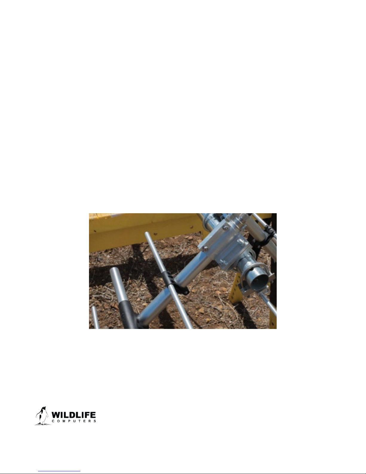
Omni-directional Antennas
1. Carefully unpack the antenna.
2. Fit the cross-arm bracket to the antenna mast and tighten.
3. At the end of the cross-arm, assemble and fit the antenna mounting bracket near the end of
the cross-arm.
Page 8
The information contained in these documents is confidential, privileged and only for the information of the intended recipient and
may not be used, published or redistributed without the prior written consent of Wildlife Computers.
Figure 2—Yagi antenna mast clamp
 Loading...