

Wilding Wallbeds Sierra 33 Instruction Booklet

For Wallbed models:
SIERRA
Revision 7/14 BK33
WARNING! ALL MURPHY/WALLBED SYSTEMS CONTAIN STORED ENERGY. FAILURE
TO USE AND FOLLOW THESE INSTRUCTIONS DURING THE INSTALLATION PROCESS
COULD RESULT IN SEVERE PERSONAL INJURY TO USER OR DAMAGE TO PRODUCT.
PLEASE CONTACT CUSTOMER SERVICE AT 866-725-6401 FOR ANY QUESTIONS.
STORAGE HEAD BOARD
INSTRUCTION BOOKLET #33

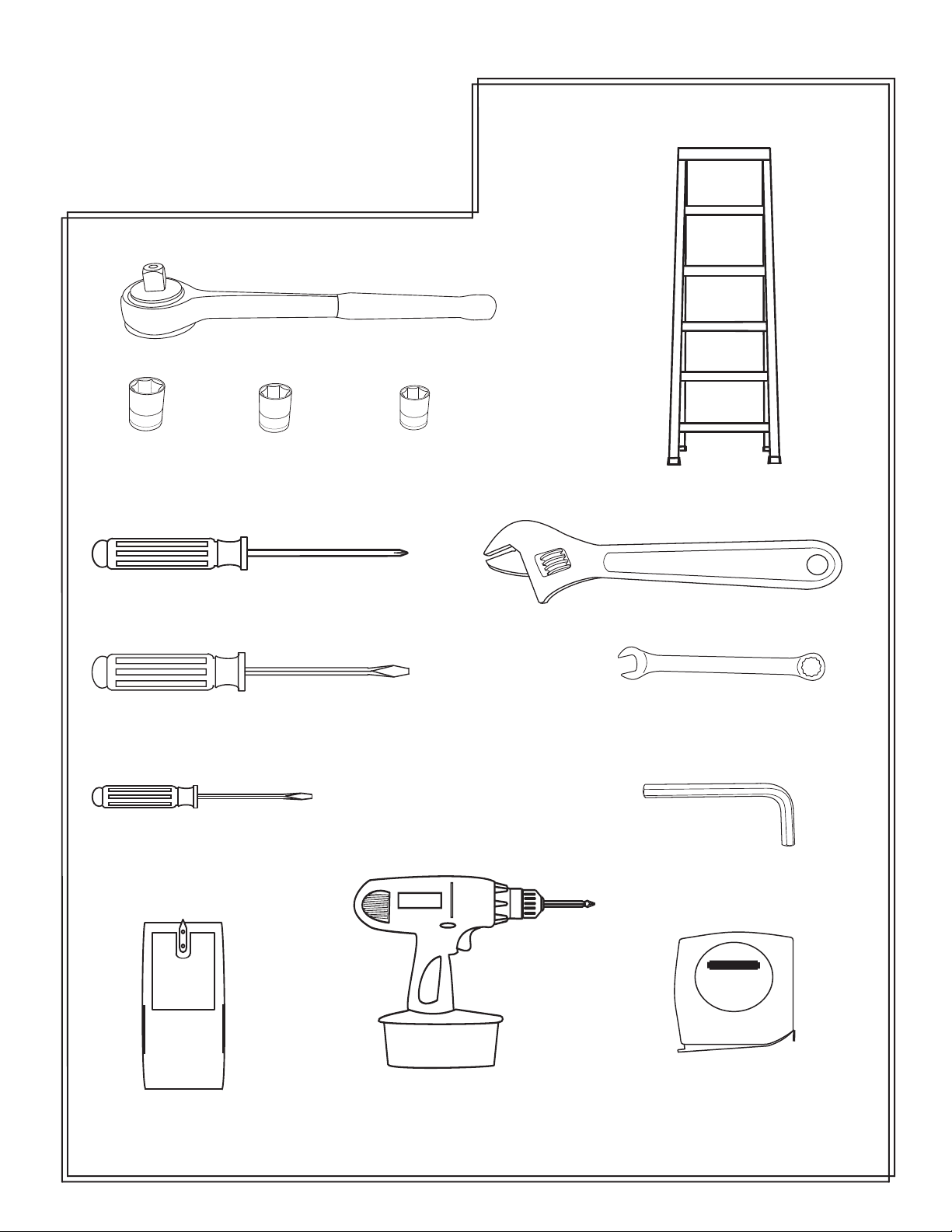
Tools Needed
Ratchet
1/2” Socket
Phillips screwdriver
Large regular screwdriver
Small regular screwdriver
7/16” Socket3/8” Socket
6 foot ladder
Cresent wrench
1/2” open end wrench
1/4” Allen wrench
studsensor
Stud finder
Cordless screw driver
with Phillips bit
STAN LEY
Tape measure
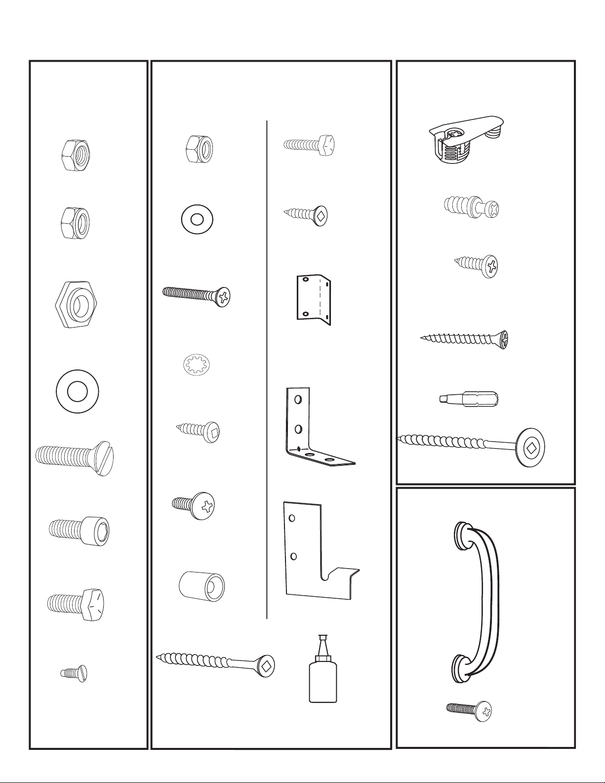
Hardware Page
Bag 7
Item
5/16’’ Plain
Hexagon Nut
5/16’’ Nylock
Hexagon Nut
3/4’’ Cam
Washer
Qty
10
6
2
Item
3/16’’ Nylock
Hexagon Nut
3/16” Washer
3/16’’x 1 Black
Flathead Screw
1/4’’
Bag 8
Qty
16
2
2
2
Item Qty
1/4’’x 3/4’’
Hex Head Bolt
3/4’’ Flat head
Screw
4 hole corner
bracket
Other Hardware
Item
2
Cam Fitting
6
Connecting Bolts
4
5/8’’ Pan
head Screw
1/4’’
1 Wood Screw
Qty
4
32
80
10
7/8” Washer
5/16’’ x 1 1/4’’
Flat Head Bolt
5/16’’ Allen
Head Bolt
5/16’’ x 3/4’’
Hex Head Bolt
4 mm x 1/4’’
Flat Head Screw
2
10
2
4
4
1/4” Star Washer
5/8’’ Pan
head Screw
3/16’’ x 1/2’’
Black Truss
head screw
Leg Stop
2’’ Flathead
Wood Screw
135
14
2
“L” Bracket
1 left
(
1 right
Spacer Plate
6
LOCTITE
Small bottle of Loc-tite
1
3
Square Tip Bit
3
1/2’’
3 Wood Screw
(for optional under mount)
Bed Handles
2
)
1
4
1”
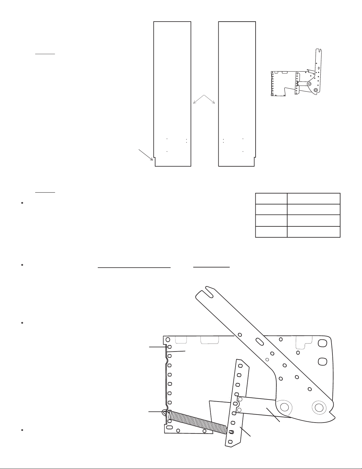
Step 1: Locate the two Side Boards. If you
purchased a Queen size bed the Side Boards
measure 85” long. Full and Twin size Side
boards will measure 80” long. From the
square white box locate the two Lift Mechanisms, hardware bag 7 and springs.
Cut out for room
base molding
Finished edge
X 2
Lift Mechanism
Left Side Board Right Side Board
Step 2:
The number of springs in the Lift Mechanism required varies with the different weights of
mattresses. If you purchased your mattress with your bed from Wilding Wallbeds refer to the
chart to the right. This will also be a good reference point for mattresses not purchased with
your Wall bed.
NOTE: After you have completed installing and checking operation of your Wallbed, you
may find it necessary to add or remove springs to achieve the correct lift effort of between
5 and 10 pounds.
Install the first spring in hole #2 for Queen and Full size beds and hole #3 for twin size on both the Mounting Plate and the
Tension Arm. Hook one end of the spring under the upturned edge of the Mounting Plate. Lay the spring down and slide it
under the matching hole in the Tension Arm. See illustration 1.
HELPFUL HINT: You may find it easier to fit the hook
under the Tension Arm if you pry up the Arm Bracket with
a wooden wedge or similar device.
Continue by working up from, hole
2 (Queen and Full size beds) or hole
3, (for twin size), until you have
installed the required number of
springs.
Install Springs in the Lift Mechanisms
Hole #9
Upturned edge of
Bed Size
Queen
Full/Double
Twin/Single
Number of Springs
8
6
4
Illustration 1
(right lift mechanism)
mounting plate
IMPORTANT! Be sure that holes
of the Mounting Plate correspond
to the holes in the Tension Arm
and use the same number of
springs and the same configura
tion on both Lift Mechanisms
-
Hole #2
Repeat Step 2 for Left Lift Mechanism.
Arm Bracket
Tension Arm
Page 1
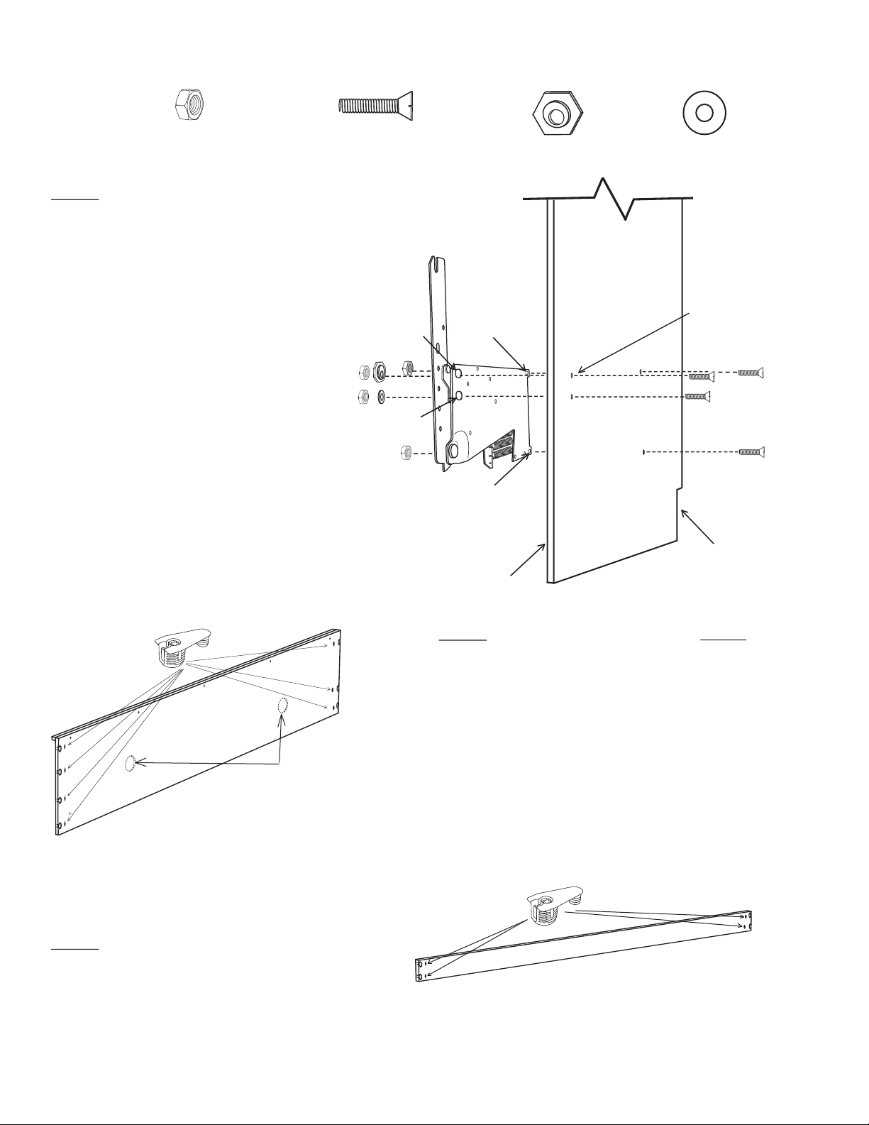
Hardware needed for next 2 steps from Bag #7
x 8
5/16” Plain Hex Nut
Step 3:
a 5/16” x 1 1/4” Flathead Machine Screw through
holes “C” and “D” from the outside (countersunk
holes) of the Right Side Board. Position the cor
responding Right Lift Mechanism holes. Loosely
thread on a 5/16” Plain Hex Nut on each. Insert the
same type screw through holes “A” and “B”. At
hole “A” use one of the Hexagon Cam Washers in
the slot of the mounting plate so that the LARGER
PART OF THE CAM IS UP. At hole “B” use a 5/
16” x 7/8” washer. Thread a nut on each. Tighten
the four nuts evenly, making sure the hexagon cam
washer does not rotate while tightening.
See illustration 2.
IMPORTANT! Over tightening the nuts will pull
the head of the screw too deeply into the Side
Board. Tighten only until the head of the screw is
flush with the Side Board.
Install the Lift Mechanism by inserting
5/16” x 1 1/4” Flathead
Slot Machine Screw
-
Hole A
Hole B
x 8
Hole C
Hole D
x 2
Hexagon Cam Washer
Right
Side Board
x 2
7/8” Washer
Illustration 2
All holes are countersunk
in this side of sideboard
Repeat step 3 with the Left Side Board and Lifting
Mechanism.
Optional holes for lights
Bridge Board has 7 fittings
Step 5:
Boards and insert four Cam Fittings into the
back of each Stretcher. Press the Cam Fit
tings in so they are tight against the part.
Locate the TWO (2) Stretcher
-
Base Board
Notch
Finished Edge
Step 4:
Cam Fittings into the sockets provided. Press the Cam
Fittings in so they are tight against the bed part. You may
need a rubber mallet to get them properly set.
Locate the Bridge Board and Insert
Helpful hint: The Bridge Board and the Head
Board are the same Length and could be eas
ily confused. Note the Bridge Board has 7 cam
fitting sockets and the Head Board has a pre
insatlled black barrel catch on the back.
SEVEN
-
X 2
Page 2
 Loading...