

Page 1
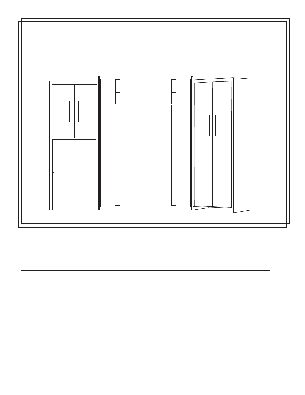
CLINICAL PRO SERIES
INSTALLATION INSTRUCTION
INSTRUCTION BOOKLET #CPS 10
Watch step by step installation instructions at:
https://www.wallbedsbywilding.com/installation-cps/
Note: Portions of the installation process will require two installers.
WARNING! ALL MURPHY SYSTEMS CONTAIN POWERFUL LIFTING COMPONENTS. FAILURE TO
USE AND FOLLOW THESE INSTRUCTIONS DURING THE INSTALLATION PROCESS COULD RESULT IN SEVERE PERSONAL INJURY TO USER OR DAMAGE TO PRODUCT. PLEASE CONTACT
CUSTOMER SERVICE AT 866-725-6401 FOR ANY QUESTIONS.
Revision 7/16
Page 2

Page 3
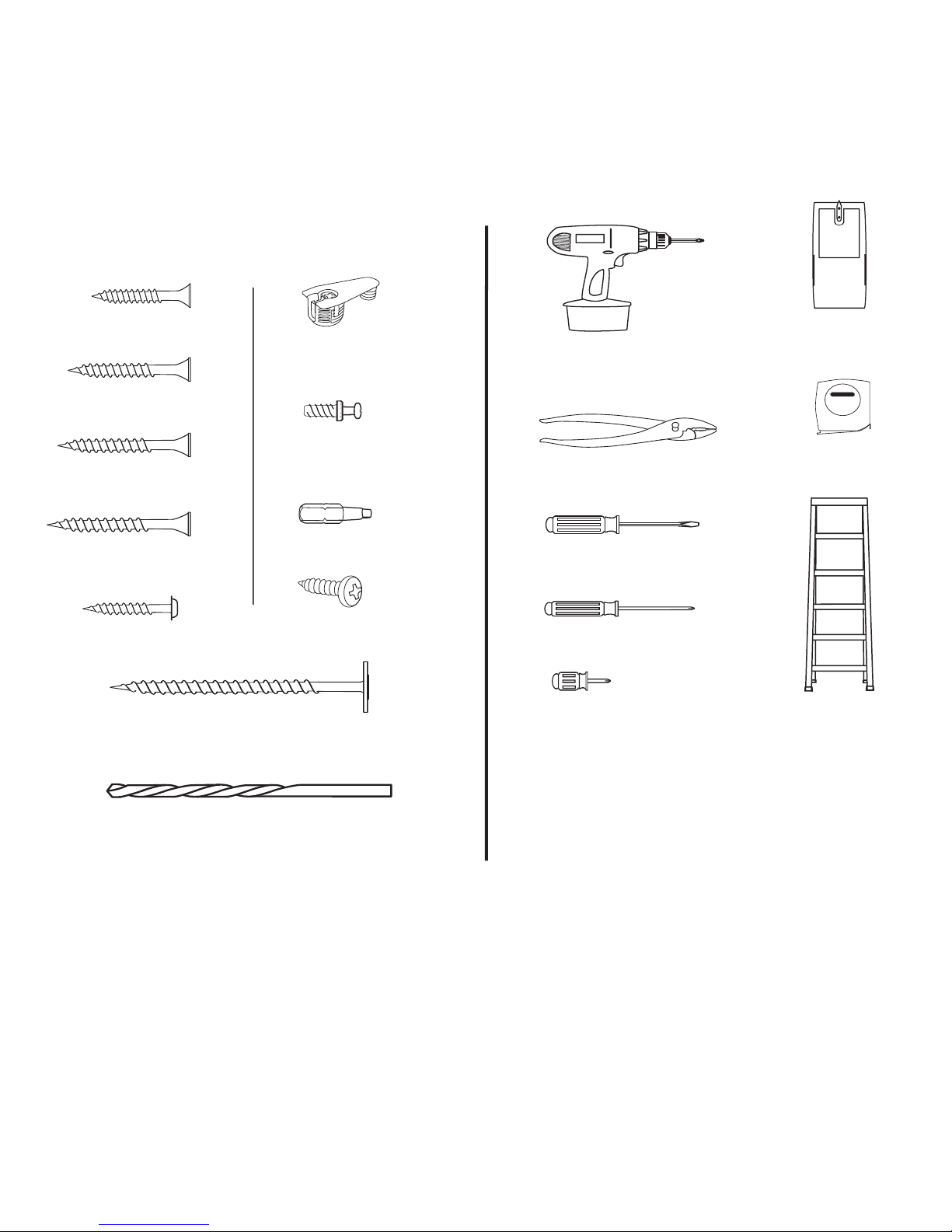
Hardware Supplied
Tools Needed
1 1/4” Wood Screw
1 1/2” Wood Screw
1 3/4” Wood Screw
2” Wood Screw
1 1/4” Pocket Hole Screw
3 1/2” Wood Screw
Qty
10
4
4
4
4
Cam Fitting
Connecting Bolt
Square Tip Bit
5/8’’ Pan head Screw
Qty
4
Spare
4
Spare
1
25
3
Cordless Screw Driver
Or Power Drill with Phillips bit
Pliers
Small Regular Screw Driver
Phillips Screw Driver
Stubby Phillips Screw Driver
Studsensor
Stud Sensor
STANLEY
Tape Measure
6’ Step Ladder
1/4” Drill Bit
(Attached to the top of the Bridge Board)
Page 1
Page 4

Wall Bed Parts List
Mattress Box (complete unit)
A
B
Bridge Board
C
Left Side Board
D
Right Side Board
E
Head Board Face
F
Head Board Top
(See Below for Head Board Parts)
G
Male Pivot Point
H
Upper Plate
Lower Plate
I
J
Female Pivot Point
K
Stretcher Board
L
Lift Piston
Handle
N
Bed Stop
M
C
Page 1
K
M
B
D
F
E
L
H
G
I
N
A
Equipment Head Board Parts List
Head Board Hinged Top
A
B
Top Shelf
C
Bottom Shelf
D
Cat 5-6
E
Head Board Face
F
Power Strip
G
Right Center Partition
H
Left Center Partition
Outer Partion
I
J
Lid Support
K
Cam/Connecting Bolt
L
1/4” Back Panel
Barrel Catch Assembly (inside)
M
Hinge Assembly (inside)
N
N
J
L
I
K
C
B
A
N
H
N
M
I
D
L
F
G
E
Page 2
Page 5
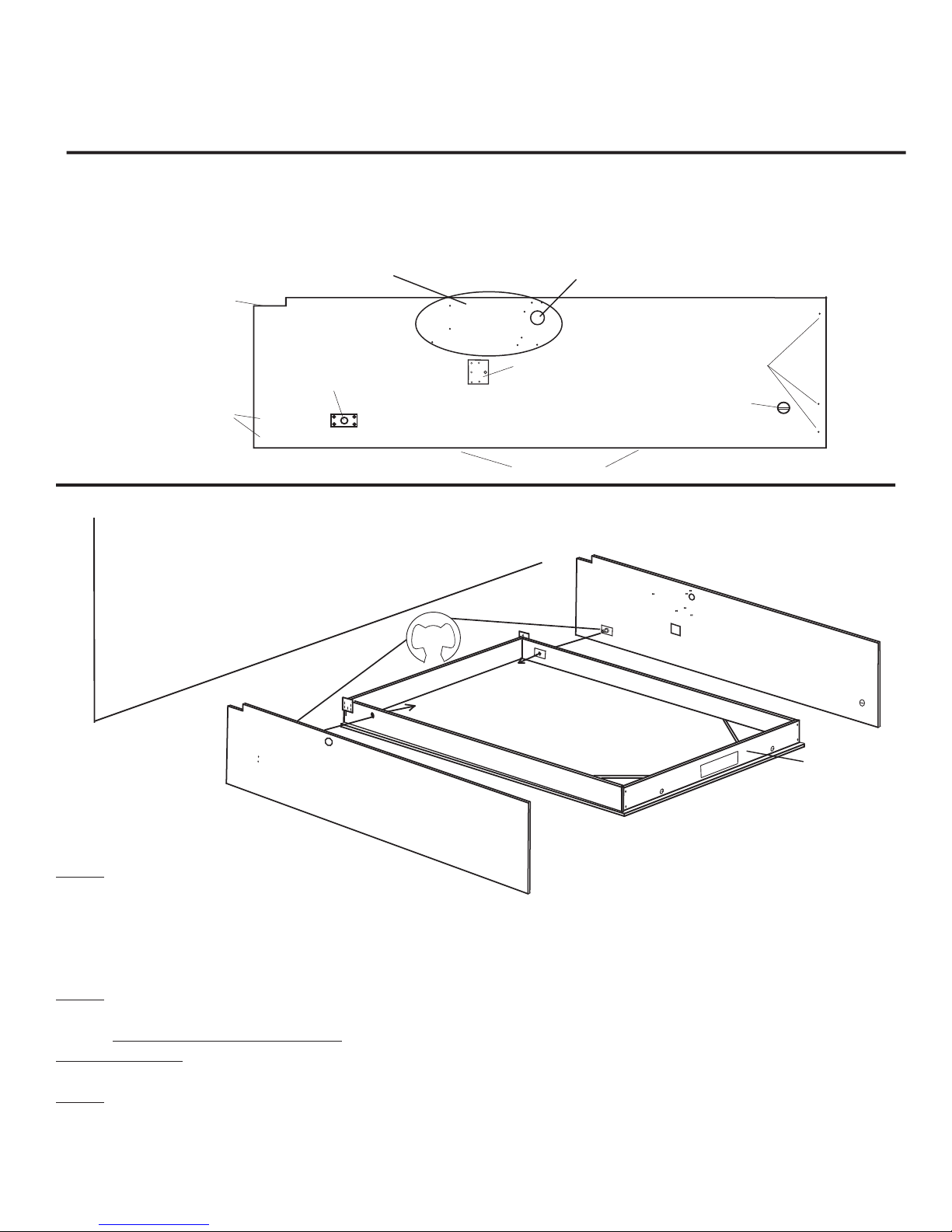
NOTICE: THE ILLUSTRATIONS IN THESE INSTRUCTION SHOW ASSEMBLY
WITH EXAM CABINET ON THE RIGHT. YOUR CABINETS AND CABINET PARTS
MAY VARY FROM THESE DRAWING IN THE FORM OF A MIRROR IMAGE.
Side Board Illustration
For ease of assembly, familiarize yourself with side board parts below.
Headboard Connecting
Base board cut out
Base board/Stretcher
Connecting Bolts
Bolts
Male Pivot post
(E-clip attached)
Upper Plate
(Right side board shown)
Finished edge
Grommet
Bridge board
Connecting bolts
Bed Stop
Installation Wall
Left Side Board
Step 1: Position the Mattress Box and the
right and left Side Boards face down on the
floor with the bottom of the Mattress Box
approximately 2.5 feet from the wall where
the bed will be installed.
Step 2: With a pair of pliers, remove the
E-clips from the pivot posts on the Side
Boards. Leave the white nylon spacers in
place on the posts.
E-clip
Right Side Board
Mattress Box
Mattress Box Top
Step 3: Slide the Side Board pivot posts
through the pivot holes in the Mattress
Box as illustrated. Replace the E-clips.
Page 3
Page 6
Upper end
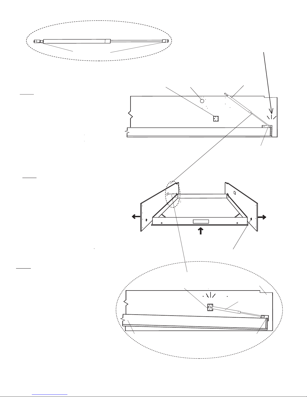
Lift Piston Illustration
Lower end
Piston Socket
: Attach the lower end of the Lift
Step 4
Piston (skinner end) onto the Lower An
chor Plate on both sides of the Mattress
Box by positioning the socket end of the
piston directly over the ball stud on the
anchor plates and pushing them on. The
piston socket will snap into place over
the ball.
Spread the Side Board tops so
Step 5:
the Mattress Box has clearance to pass
through the Mattress Box Stops on the
Side Boards. (Illustration 1)
Upper Anchor Plate
Grommet
Hole
Piston
-
Left Side Board
Mattress Box
Lower Anchor Plate
Mattress Box
Snap
This step will require two people.
Step 6:
One person will kneel down in front of
the Mattress Box and lift it up about 4 to 5
inches while the second person positions
the upper socket end of the Lift Piston
directly over the ball stud on the upper an
chor plate and snap it into place. The first
person may need to raise and lower the
Mattress Box slightly to allow the Piston
to snap on. Repeat step on opposite piston
to be snapped into place. (Illustration 2)
Illustration 1
Upper anchor plate
Left side board
Mattress
Page 4
box (slightly raised)
Mattress Box Stop
Snap
Illustration 2
Base board cut out
Piston
Lower anchor plate
Page 7
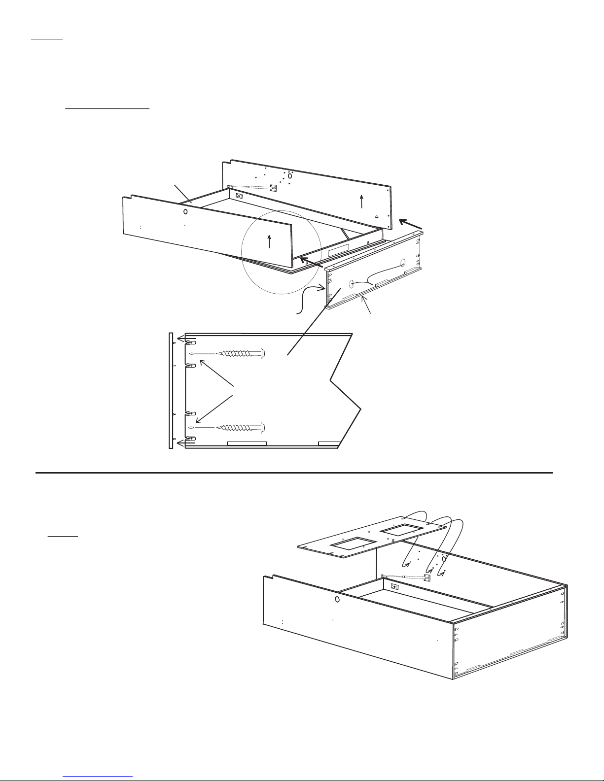
Step 7:
on the right side of the Bridge Board, tighten the Cam fittings using a Phillips screw driver turning them 1/2 turn
clockwise. Do this procedure by hand to insure the Cam fittings are tight but not over tightened. DO NOT USE A
POWER SCREW DRIVER. Once the Cam fittings are tight insert two (per side) pocket hole screws into the Pocket
Holes and screw them into the Side Boards.
Position the Bridge Board by inserting the 3 connecting bolts on the right Side Board into the 3 Cam Fittings
HELP FULL HINT
: It is easier to engage the Bridge Board’s cam fittings to the
Side Boards if you (with your helper) raise the end of the Side Boards just above
the Bed Box. Raise both Side Boards at the same time as you fit the Bridge Board
Mattress Box Bottom
Bridge Board
Optional light holes
Finished side
Finished edge
Step 8:
Install the Head Board Face with
the Wall Bed remaining face down on
the floor.
WITH THIS STEP.
HAVE SOMEONE HELP
Slide the Headboard
between the Side Boards and under the
Connecting Bolts line it up with the Con
necting Bolts as illustrated. Now with
a Phillips screw driver tighten the Cam
fittings by turning them clockwise.
Pocket Holes
Bridge Board
Cam Fittings up
-
Page 5
Page 8
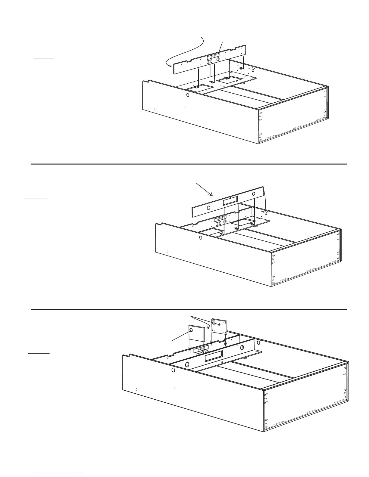
Cam Fittings on this side.
Power strip
Step 9:
Install the Head Board
Bottom Shelf as illustrated.
Make sure to orient the self as
shown with the Cam Fittings
down.
Step 10:
Install the Head
Board Top Shelf as illustrated.
Make sure to orient the shelf as
shown with the Cam Fittings
down.
Bottom
Cam Fittings on this side
Step 11:
Install the two Center
Partitions as illustrated. Make
sure to orient the partitions as
shown with the Cam Fittings
facing each other toward the
INSIDE. Grommet holes down.
Bottom
Cam Fittings on this side
Grommet
Bottom
Page 6
Page 9
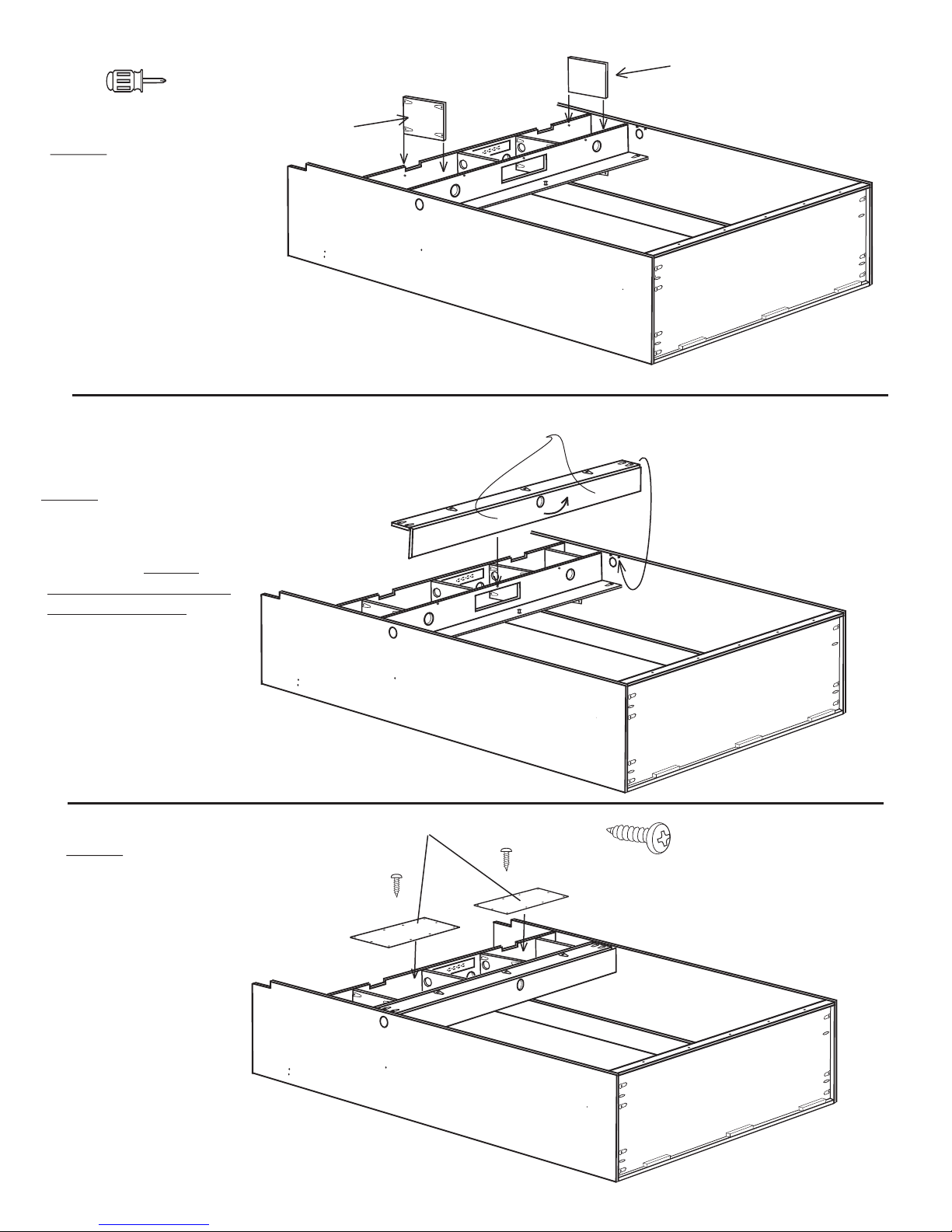
Step 12:
Outer Partitions as illus
Install the two
trated. Make sure to orient
the partitions as shown with
the Cam Fittings facing
OUTSIDE. Use the Stubby
Phillips screw driver if
necessary to tighten Cam
Fittings.
Step 13: Install the Hinged
Head Board Top as illus-
trated.
Cam Fittings
on this side.
Cam Fittings
on this side.
Bottom
Hinged Headboard Top
Helpful hint: Lift the
Hinged Top to get the unit
positioned correctly. Once in
place snap the barrel catch
together holding the Hinged
Head Board Top closed.
Step 14:
Install the two 1/4”
plywood back panels using
the 5/8” Screws provided.
Bottom
1/4” Back Panel
20
5/8’’ Pan head Screw
Bottom
Page 7
Page 10
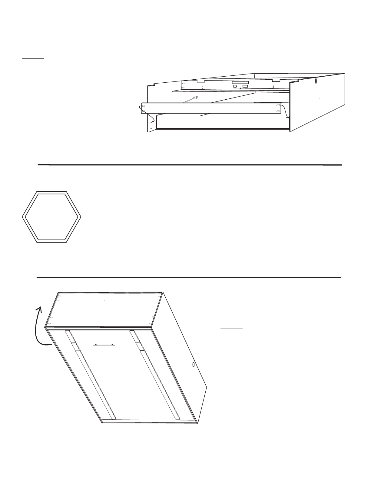
Step 15: Locate the Stretcher Board and slide
it between the Side Boards at the bottom of
the Wall Bed Cabinet. Insert the Cam Fittings onto the Connecting Bolts and tighten
them by turning the cam clockwise.
If Wall Bed lights were purchased for the bed, you must install the lights at this point
STOP
in the installation process. Light Kit instructions are included in the Light Kit box.
Stretcher Board
Step 16: This step will require 2 people.
From the top of the Wall Bed Cabinet,
lift it to the standing position. Be careful, the front is heavier and the unit may
not stand on its own.
Page 8
Page 11
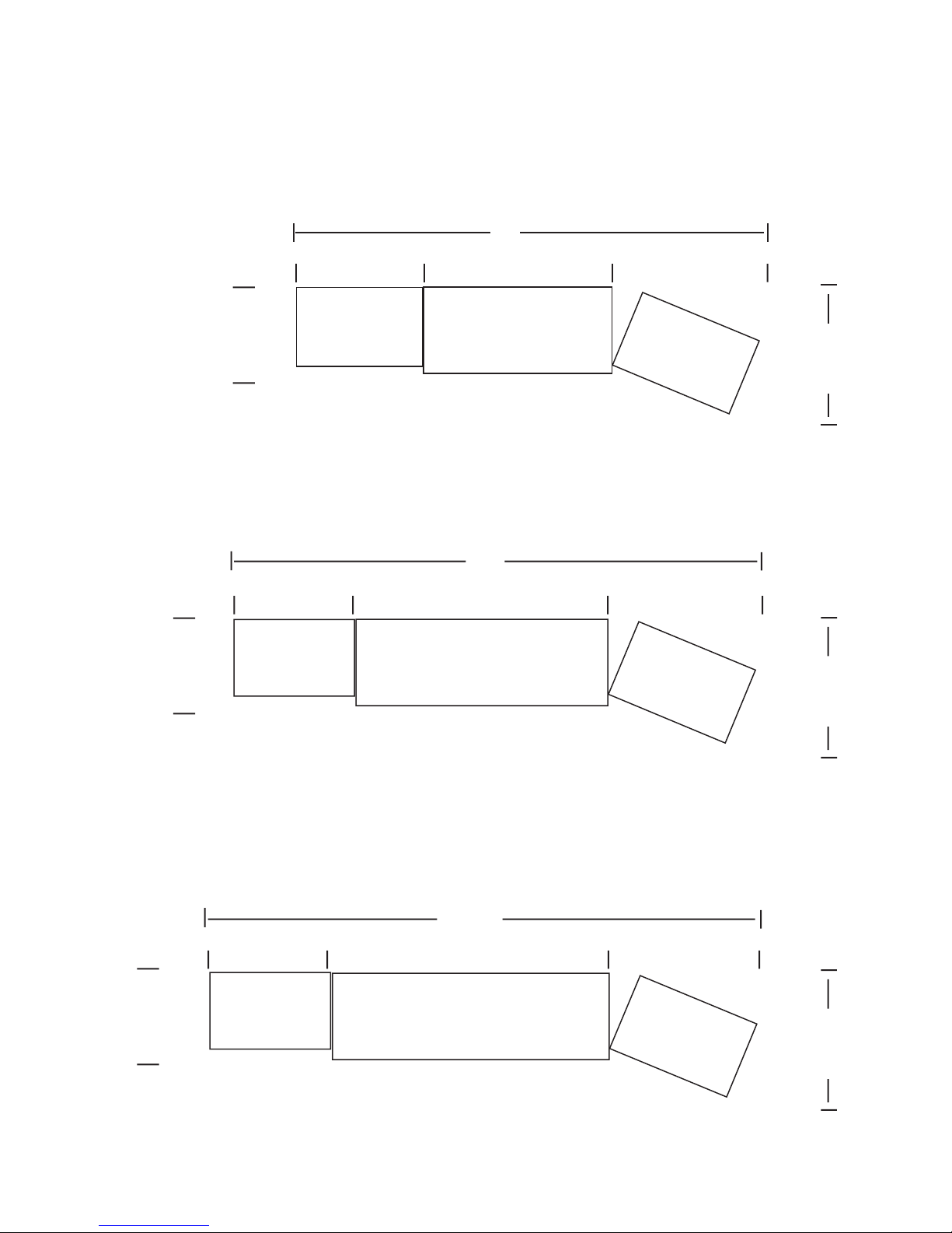
Positioning Unit in Room
The following illustration is a birds eye view with dimensions to be considered in locating the unit during
installation. The illustration shows the Exam cabinet on the right but your unit may have it on the left.
TWIN SIZE UNIT
109”
Overall Height of unit
23”
23”
86.5”
30”
Cabinet
30”
Cabinet
43”
TWIN SIZE
Wall Bed
FULL SIZE UNIT
124”
58”
FULL SIZE
Wall Bed
36”
Exam
Cabinet
36”
Exam
Cabinet
30”
29.25”
30”
29.25”
Overall Height of unit
23”
Overall Height of unit
Cabinet
86.5”
30”
86.5”
QUEEN SIZE UNIT
130”
64”
QUEEN SIZE
Wall Bed
Page 9
36”
Exam
Cabinet
30”
29.25”
Page 12
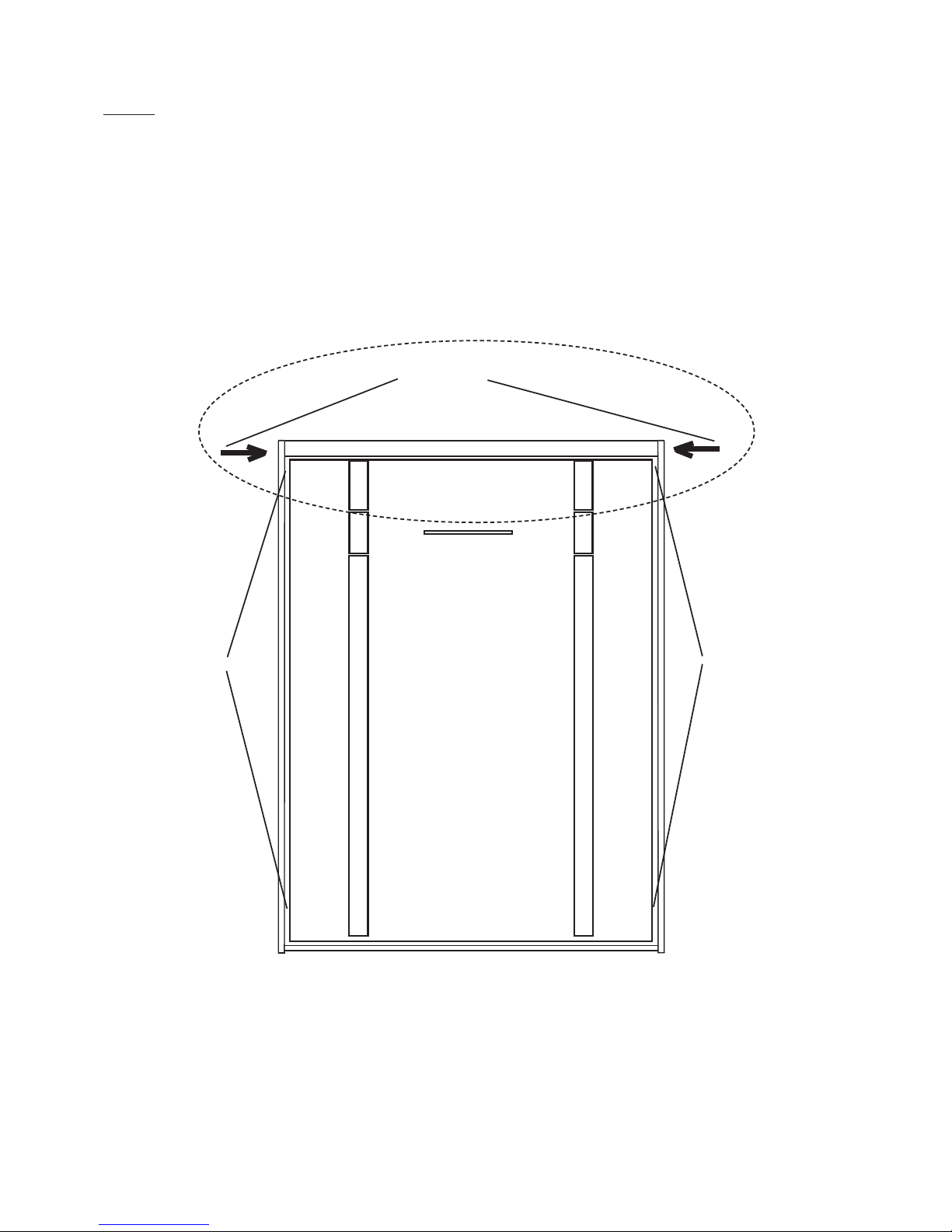
Step 17: Once the Wall Bed is standing, slide it back and position
it against the wall where it is to be installed (See page 7) . Check
the gap between the Side Boards and the Mattress Box Front on
both sides. The gap at this point will probably need to be adjusted. You can adjust the gap by pushing a Side Board to one side
or the other at the top. Pushing it will even out the gap from top
to bottom on each side. At this point don’t worry if one side has
a larger gap than the other as long as each side’s gap is about the
same from top to bottom.
(Illustration 4)
PUSH HERE....OR HERE TO ADJUST GAP
Illustration 4
Gap
Gap
Page 10
Page 13
WARNING: THE NEXT 2 STEPS MAY REQUIRE PROFESSIONAL HELP.
FAILURE TO PROPERLY ANCHOR THE WALL BED TO YOUR WALL COULD CAUSE THE UNIT TO
FALL CAUSING SEVERE PERSONAL INJURY OR DEATH.
CALL TECHNICAL SUPPORT AT 866-725-6401 IF YOU HAVE ANY QUESTIONS.
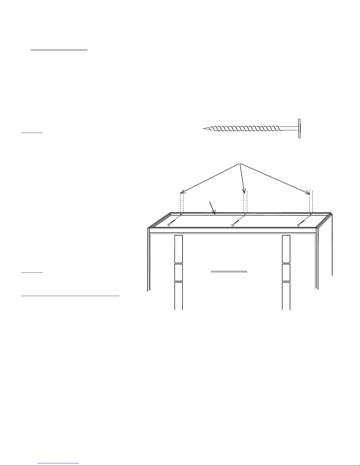
Step 18: Standing on a ladder in front
of the Wall Bed, locate the studs in your
wall with a stud finder, then mark them
with a pencil just above the Anchor
Board located at the back of the Bridge
Board. (See illustration 5) You should be
able to find at least 3 studs for Queens
and Fulls, Twin size units require 2. It is
highly recommended that you run a test
screw into your wall just above the Anchor Board to verify that you have found
the stud location. IF YOUR WALLS
ARE NOT TRADITIONAL WOOD
FRAMING, YOU MAY NEED TO
HIRE A HANDY MAN OR CONTRACTOR TO HELP IN ANCHORING THE
UNIT SECURELY TO YOUR WALL.
Step 19: Using a 1/4” drill bit (provided)
pre-drill holes through the Anchor Board
corresponding with the studs in your wall
DO NOT PRE-DRILL THE STUDS.
Now, using the 3 1/2” Wood Screws,
(or screws appropriate for your wall
type) anchor the Wall Bed to the wall.
Anchor
Board
3 1/2” Wood Screw
Studs in your wall
Illustration 5
Bridge
Board
Page 11
Page 14
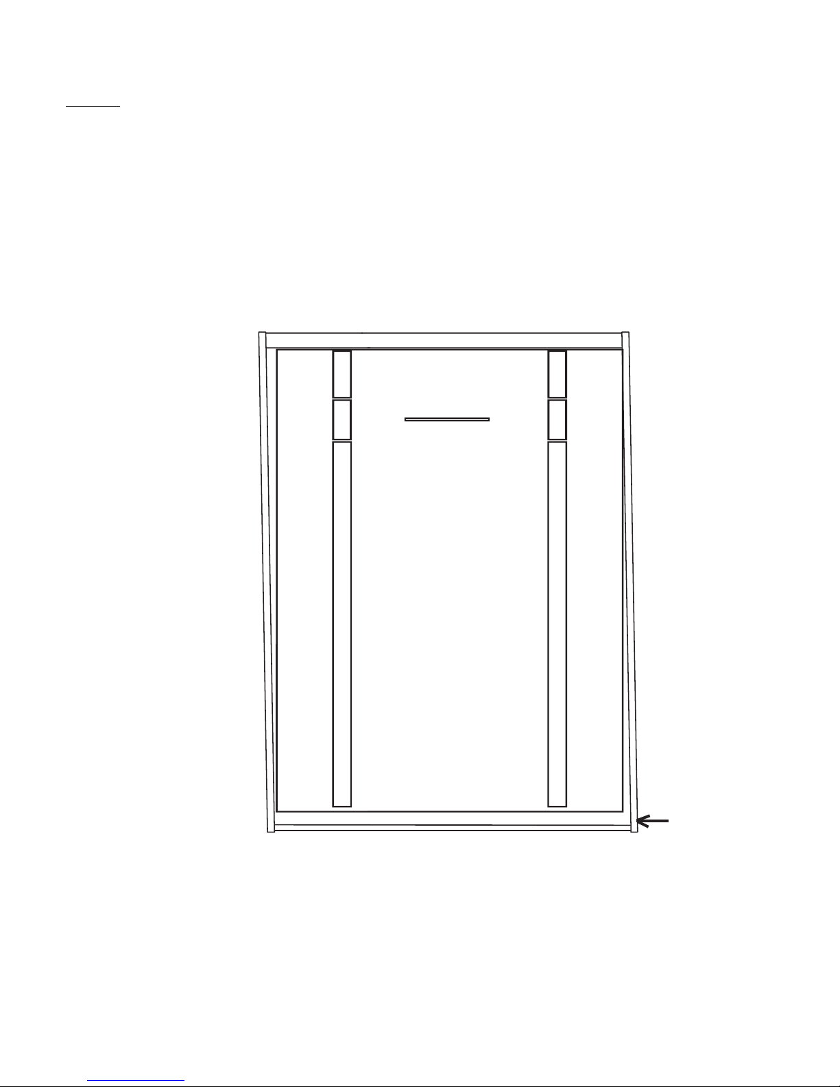
Step 20: Check the gap alignment again. If it looks right skip this
step. If the gap is not right, meaning that the Mattress Box is too
close to the side board or even touching it at the top on one side. It
can be adjusted even after the Wall Bed is attached to the wall but it
will require two people. The procedure will require the bottom of the
Wall Bed Cabinet to be moved slightly to the left or right depending
on which top corner is too close. If the Mattress Box is too close on
the top right side for instance, the right side (bottom) will need to be
slid to the left slightly. Have one person push the Side Board at the
bottom with his feet while the second person pulls at the opposite
bottom side.
Push sideboard over
at bottom
to align
Page 12
Page 15
STOP
ONLY PERFORM THE FOLLOWING STEP IF THE
EXAM TABLE IS TO BE POSITIONED AT A 22.5
ANGLE TO THE SIDE OF THE WALL BED.
Angle Supports are designed to assist in positioning and
anchoring the Exam Cabinet at a 22.5 degree angle to
the Wall Bed. It is important that the Exam Cabinet be
mounted to the Wall Bed to gain support for operating the
exam table. THE EXAM CABINET WILL FALL OVER
UPON OPENING THE EXAM TABLE IF IT IS NOT AT
TACHED TO THE WALL BED OR WALL PROPERLY.
NOTE: these instructions illustrate the Exam
Cabinet being positioned to the RIGHT of the
Wall Bed, your installation may be a mirror im
age of these instructions.
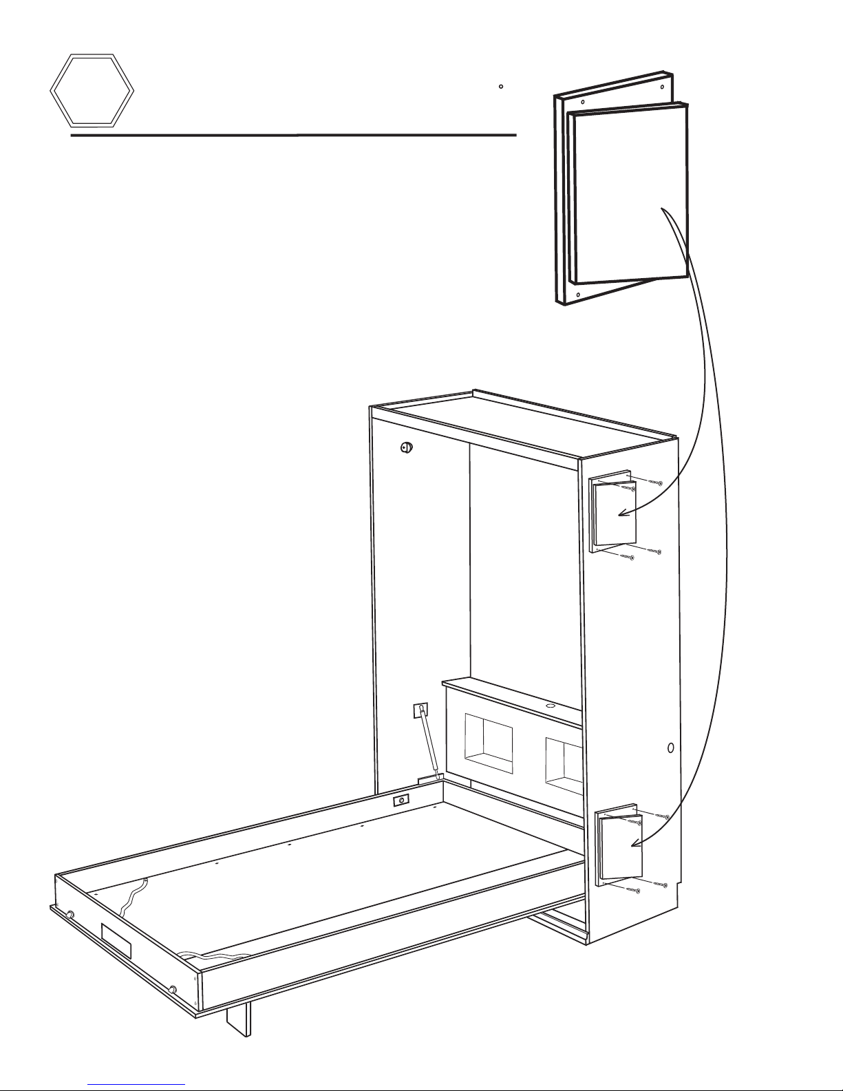
Step 21 (Option step) Using
four 1.5” wood screws for each
support, attach the exam cabinet
supports to the Wall Bed’s Side
Board as illustrated. Note that
there are small pre drilled holes
in the side board for proper po
sitioning of the Angle Supports.
-
Exam
Cabinet
Angle
Supports
-
-
Warning, the Exam Cabi
net will need to be prop
erly attached to the Wall
Bed via the exam cabinet
supports to prevent the
exam cabinet from tipping
over.
-
-
Page 13
Page 16

Step 22: With the Exam Cabinet evenly in place against the Angle Supports and the front corner against the Wallbed 2” back, use 1 3/4” wood screws through the holes provided right behind the face frame of the Exam Cabinet to fasten the front edge of the cabinet to the Wallbed.
4
1 3/4” Wood Screw
Face Frame
Wallbed
Top View
Angle Support
Flush against corner support
Exam
Cabinet
Corner touching
Wallbed 2” back
Page 14
Page 17
WARNING! THE NEXT STEP REQUIRES TWO
PEOPLE. DO NOT OPEN THE EXAM TABLE
ALONE IT WILL FALL OVER.
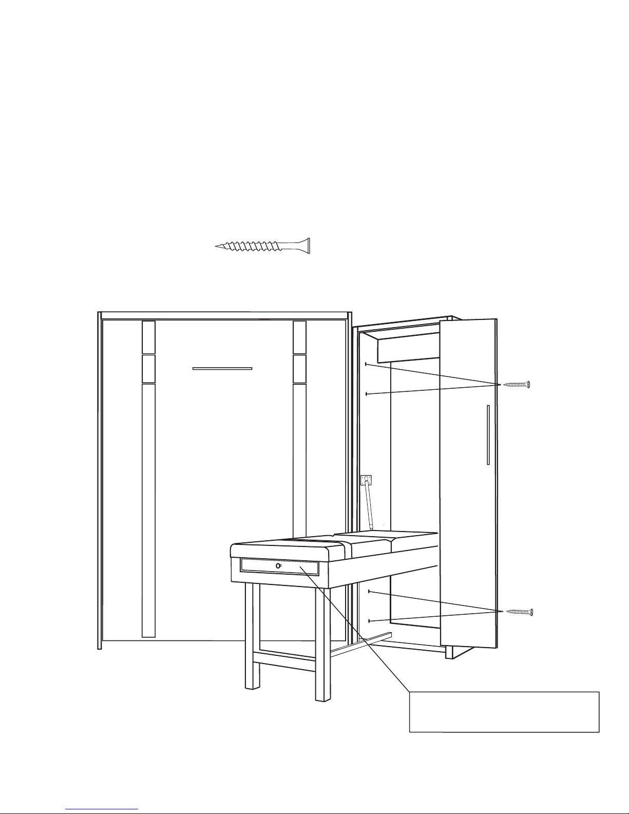
Step 23: While someone holds the Exam Cabinet to prevent it from falling over, carefully pull down the
exam table and insert four 2” long wood screws through the holes provided in the side panel of the cabinet
driving the screws into the Angle Supports attached to the Wall Bed’s cabinet as illustrated below.
4
2” Wood Screw
WARNING Exam Cabinet must be
attached properly to the Wall Bed or
wall. Failure to properly attach cabinet could result in cabinet falling over
resulting in injury.
WARNING: Do not sit on foot rest,
MAX weight 150LBS
Page 15
Page 18
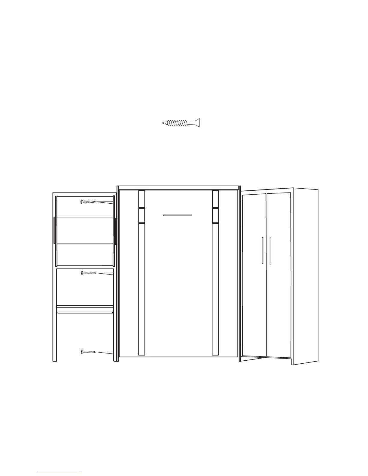
Step 24: Position the Diagnostic cabinet (Or other type Cabinet) next to the
Wall Bed and attach it to the Bed using
1.25” screws through holes drilled in
the side of the cabinet.
6
1 1/4” Wood Screw
Page 16
 Loading...