

Wilding Wallbeds C124 Instruction Booklet

Revision 4/16 C124
INSTRUCTION BOOKLET #C124
For Wallbed models:
KING SIZE PARK CITY
WITH STORAGE
HEADBOARD
WARNING! ALL MURPHY/WALLBED SYSTEMS CONTAIN STORED ENERGY. FAILURE TO USE AND
FOLLOW THESE INSTRUCTIONS DURING THE INSTALLATION PROCESS COULD RESULT IN SEVERE
PERSONAL INJURY TO USER OR DAMAGE TO PRODUCT. PLEASE CONTACT CUSTOMER SERVICE AT
866-725-6401 FOR ANY QUESTIONS.
Watch step by step installation instructions at:
https://www.wallbedsbywilding.com/wallbed-installation-studio-series/

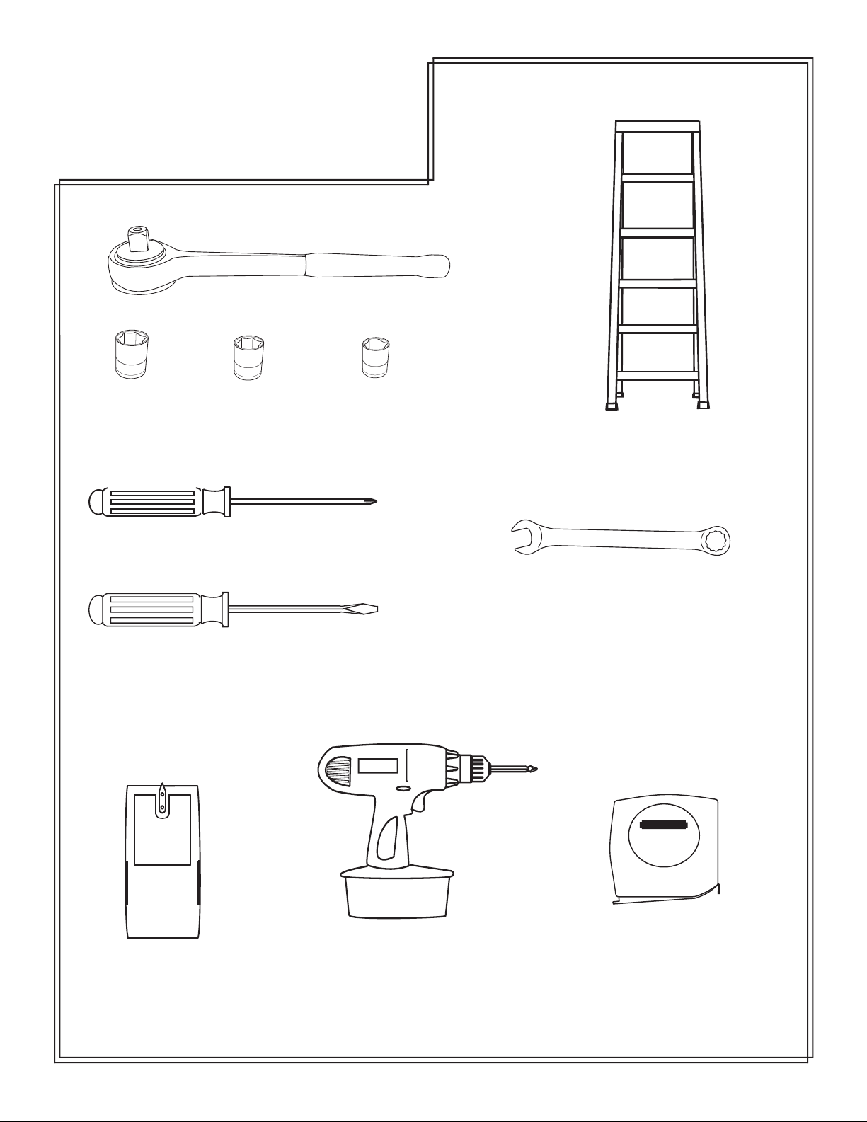
Tools Needed
Ratchet
13mm Socket
Phillips screwdriver
Large regular screwdriver
11mm Socket
8mm Socket
6 foot ladder
13 mm open end wrench
studsensor
Stud finder
Cordless screw driver
with Phillips bit
STAN LEY
Tape measure
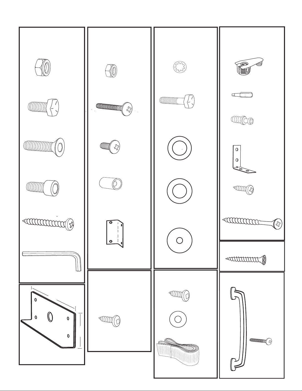
Hardware Page
Pack 2
5/16’’ Nylock
Hex Nut
5/16’’ x 1”
Hex Head Bolt
5/16’’ x 1 1/4’’
Allen Head Bolt
16
4
10
Pack 3
QtyItem
Item
Qty
Pack 4
Item Qty
Other Hardware
(From Manila Envelope)
Item Qty
4
(Extra)
10-24 Black
Nylock Nut
16
Star Washer
2
Cam Fitting
1
2
Square Tip Bit
2
10-24 x 1 Black
Machine Screw
1/4’’
14
1/4’’ x 1 1/2’’
Hex Head Bolt
Connecting Bolts
4
36
3
10-24 x 1/2’’ Black
Machine Screw
1 1/2” Nylon washer
“L” Bracket
5/16’’ x 1”
Tapered Allen Head Bolt
1 5/8’’ Pan head
Wood Screw
5/16” Allen wrench
6’’
2
1/2” x 3/4”
Black Barrel
(Leg Stop)
2
2
2
5/8’’ Pan head Screw
1 1/2” x 5/16”
Black washer
4
2’’ Wood Screw
2
6
6
Optional hardware:
1”x 1” x 1 3/4”
Four Hole Corner
Bracket
1 1/2” X .765”
Black washer
For bed designs using crown molding.
12
1/4’’
1 Wood Screw
Pack 5
Pack 7
Item Qty
2
Item
2.5’’
5/8’’ Pan
head Screw
Qty
160
5/8’’ Pan head Screw
2
3/4’’ Washer
Bed Handles
Machine Screw
Qty
2
Qty
4
Panel Saver
(In mechanism rails box)
3/8’’
1
2
Velcro Retainer Straps
2
NOTE: Handle
may vary depending on bed style.
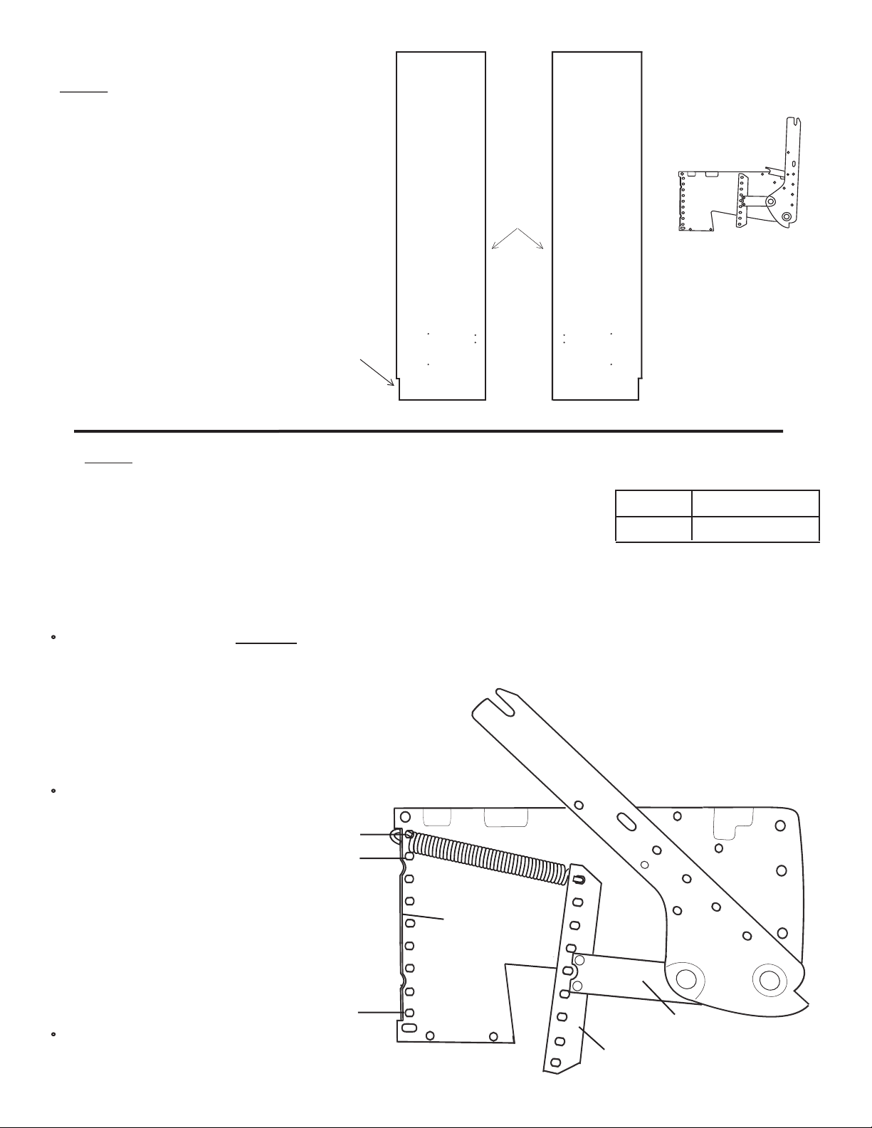
Step 1: Locate the two Side Boards. If you pur-
chased a King or Queen size bed the Side Boards
measure 85.25” long. Then from the small square
cardboard box locate the two Lift Mechanisms,
hardware bags, and springs.
Cut out for room
base molding
Finished edge
Lift Mechanism
Left Side Board Right Side Board
Step 2: Install Springs in the Lift Mechanisms
The required number of springs in the Lift Mechanisms varies with the different weights of
mattresses. If you purchased your mattress with your bed from Wilding Wallbeds refer to the
chart to the right. This will also be a good reference point for mattresses not purchased with
your Wall bed.
NOTE: After you have completed installing and checking operation of your Wallbed, you
may find it necessary to add or remove springs to achieve the correct lift effort of between
5 and 10 pounds.
Install the first spring in hole #1 for king, #2 for queen on both the Mounting Plate and the Tension Arm. Hook one end of
the spring under the upturned edge of the Mounting Plate. Lay the spring down and slide it under the matching hole in the
Tension Arm. See illustration 1.
HELPFUL HINT: You may find it easier to fit the hook
under the Tension Arm if you pry up the Arm Bracket with
a wooden wedge or similar device.
(Some springs may be pre-installed)
Bed Size
King
Queen
Number of Springs
Illustration 1
Continue by working down from,
hole 1 (king size beds) or hole 2, (for
queen size), until you have installed
the required number of springs.
Hole #1
(Right lift mechanism)
Hole #2
9
7
IMPORTANT! Be sure that holes
of the Mounting Plate correspond
to the holes in the Tension Arm
and use the same number of
springs and the same configuration on both Lift Mechanisms
Repeat Step 2 for Left Lift Mechanism.
Hole #9
Upturned edge
of mounting
plate
Arm Bracket
Tension Arm
Page 1
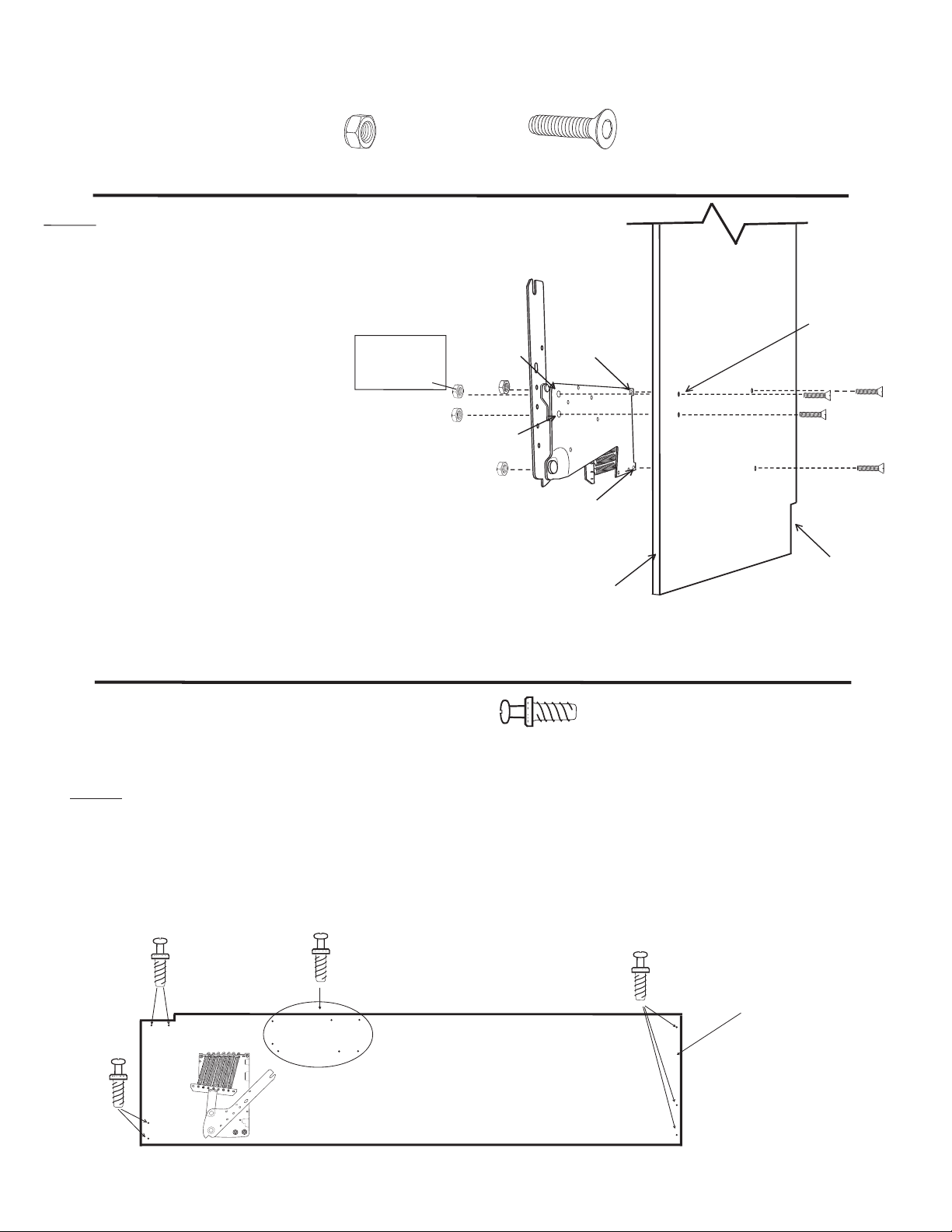
Hardware needed for next step from Pack #2
5/16’’ Nylock Nut
Step 3:
Install the Lift Mechanism to
the Side Board by inserting a 5/16 x 1
1/4” Tapered Allen head Bolt through
holes A, B, C and D from the outside
(countersunk holes) of the Side Board.
The bolt then goes through the corresponding holes of the Right Lift
Mechanism as illustrated. Thread on
four 5/16” Nylock nuts and tighten
(hole A may have threaded collar
instead of bolt)
IMPORTANT! Over tightening the nuts will
pull the head of the bolt too deeply into the
Side Board. Tighten only until the head of the
bolt is flush with the surface of the Side Board .
Repeat step 3 with the Left Side
Board and Lift Mechanism.
x 8
Note:
May be threaded
collar instead of
bolt in hole A.
5/16’’ x 1 1/4’’
Tapered Allen Head Bolt
Hole A
Hole B
Hole C
Hole D
Finished Edge
x 8
Right
Side Board
All holes are
countersunk in
this side of sideboard
Base Board
Notch
Hardware needed for next step:
Connecting Bolt
Step 4: Lay the right Side Board down and screw 14 Connecting Bolts into
the holes provided as shown. Repeat the process with the left Side Board
which will require 15 Connecting Bolts.
Note: Screw the connecting bolts down until the collar of the connecting bolt is seated firmly against the surface of the wood.
One in each
of the 7 holes
x 29
(From Manila Envelope)
Note: The left Side
Board will have a
fourth hole in this location for a Connecting
Bolt.
Page 2
 Loading...