

Page 1

Side Mount
Revision 7/13 BK22
INSTRUCTION BOOKLET #22
WARNING! ALL MURPHY/WALLBED SYSTEMS CONTAIN STORED ENERGY. FAILURE
TO USE AND FOLLOW THESE INSTRUCTIONS DURING THE INSTALLATION PROCESS
COULD RESULT IN SEVERE PERSONAL INJURY TO USER OR DAMAGE TO PRODUCT.
PLEASE CONTACT CUSTOMER SERVICE AT 866-725-6401 FOR ANY QUESTIONS.
Page 2

Page 3
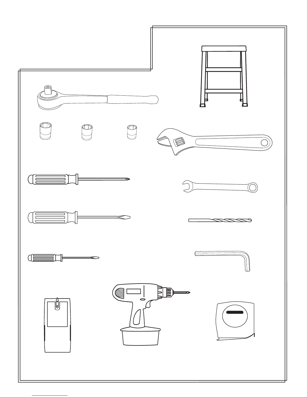
Tools Needed
Ratchet
Step Ladder
1/2” Socket
Phillips screwdriver
Large regular screwdriver
Small regular screwdriver
3/8” Socket
7/16” Socket
Crescent wrench
1/2” open end wrench
1/4” wood drill bit
1/4” Allen wrench
studsensor
Stud finder
Cordless screw driver
with Phillips bit
STAN LEY
Tape measure
Page 4
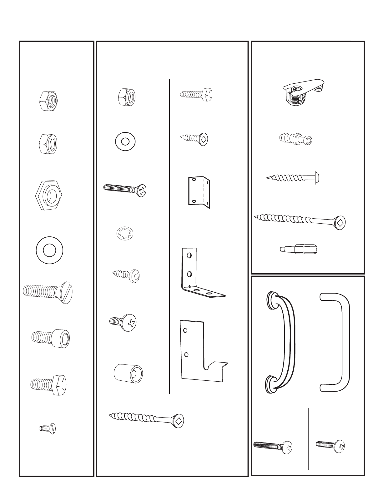
Hardware Page
Bag 7
Item
5/16’’ Plain
Hexagon Nut
5/16’’ Nylock
Hexagon Nut
3/4’’ Cam
Washer
Qty
10
6
2
Item
3/16’’ Nylock
Hexagon Nut
3/16” Washer
3/16’’x 1 Black
Flathead Screw
1/4’’
Bag 8
Qty
16
2
2
2
Item
1/4’’x 3/4’’
Hex Head Bolt
3/4’’ Flat head
Screw
4 hole corner
bracket
Qty
Other Hardware
Item
2
Cam Fitting
6
Connecting Bolts
4
1/4’’
1 Square Drive
Wood Screw
1/2’’
3 Wood Screw
Qty
4
32
160
3
7/8” Washer
5/16’’ x 1 1/4’’
Flat Head Bolt
5/16’’ Allen
Head Bolt
5/16’’ x 3/4’’
Hex Head Bolt
4 mm x 1/4’’
Flat Head Screw
2
10
2
4
4
1/4” Star Washer
5/8’’ Pan
head Screw
3/16’’ x 1/2’’
Black Truss
head screw
Leg Stop
2’’ Flathead
Wood Screw
135
14
2
“L” Bracket
Spacer Plate
6
1 left
(
1 right
1
3
Square Tip Bit
Bed Handles
2
)
Bed Models
Remington
Newport
Aspen
7/16’’
1
Dakota
4
1”
4
Page 5
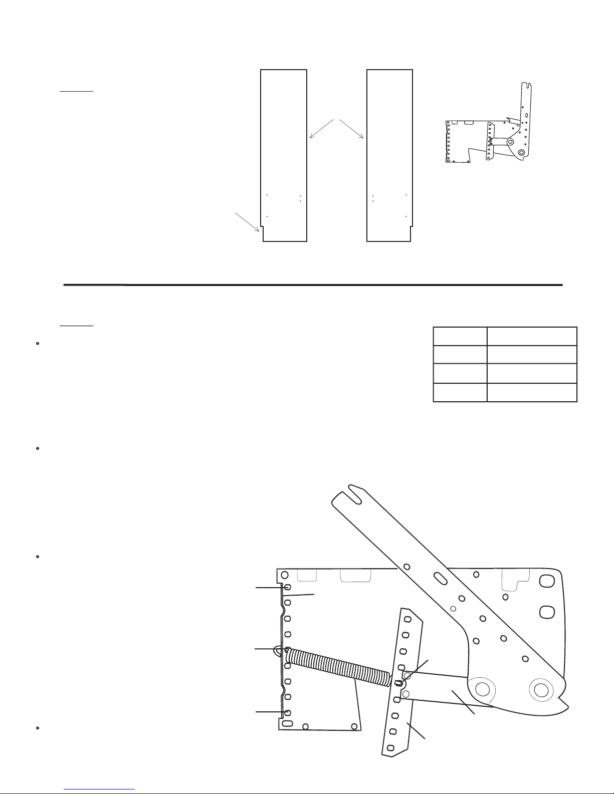
Step 1: Locate the left and right Side Boards
and then from the square white box locate
the two Lift Mechanisms, hardware bags and
springs.
Cut out for room
base molding
Finished edge
X 2
Lift Mechanism
Left Side Board Right Side Board
Step 2:
The number of springs in the Lift Mechanism required varies with the different weights of
mattresses. If you purchased your mattress with your bed from Wilding Wallbeds refer to the
chart to the right. This will also be a good reference point for mattresses not purchased with
your Wall bed.
NOTE: After you have completed installing and checking operation of your Wallbed, you
may find it necessary to add or remove springs to achieve the correct lift effort of between
5 and 10 pounds.
Install the first spring in hole #5 (center position) on both the Mounting Plate and the Tension Arm. Hook one end of the
spring under the upturned edge of the Mounting Plate. Lay the spring down and slide it under the matching hole in the
Tension Arm. See illustration 1.
HELPFUL HINT: You may find it easier to fit the hook
under the Tension Arm if you pry up the Arm Bracket with
a wooden wedge or similar device.
Install Springs in the Lift Mechanisms
Bed Size
Queen
Full/Double
Twin/Single
Number of Springs
Illustration 1
Continue by working out from the
center, alternating top and bottom,
until you have installed the required
number of springs.
Hole #1
Upturned edge of
(Right lift mechanism)
mounting plate
5
3
1
IMPORTANT! Be sure that holes
of the Mounting Plate correspond
to the holes in the Tension Arm
and use the same number of
springs and the same configura
tion on both Lift Mechanisms
Repeat Step 2 for Left Lift Mechanism.
-
Hole #5
(Center)
Hole #9
Hole #5
(Center)
Arm Bracket
Tension Arm
Page 1
Page 6
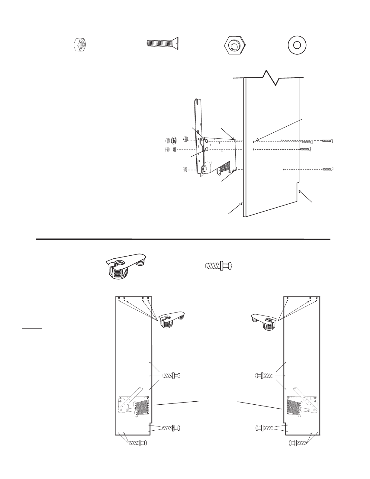
Hardware needed for next 2 steps from Bag #7
x 8
5/16” Plain Hex Nut
5/16” x 1 1/4” Flathead
Slot Machine Screw
Step 3: Install the Lift Mechanism by inserting a 5/16”
x 1 1/4” Flathead Machine Screw through holes “C”
and “D” from the outside (countersunk holes) of the
Right Side Board. Position the corresponding Right Lift
Mechanism holes. Loosely thread on a 5/16” Plain Hex
Nut on each. Insert the same type screw through holes
“A” and “B”. At hole “A” use one of the Hexagon
Cam Washers in the slot of the mounting plate so that
the LARGER PART OF THE CAM IS UP. At hole
“B” use a 5/16” x 7/8” washer. Thread a nut on each.
Tighten the four nuts evenly, making sure the hexagon
cam washer does not rotate while tightening.
See illustration 2.
IMPORTANT! Over tightening the nuts will pull
the head of the screw too deeply into the Side Board.
Tighten only until the head of the screw is flush with
the Side Board.
Repeat step 3 with the Left Side Board and Lifting
Mechanism.
x 8
Hole A
Hole B
Hexagon Cam Washer
Hole C
Hole D
Finished Edge
x 2
Right
Side Board
x 2
7/8” Washer
Illustration 2
All holes are countersunk
in this side of sideboard
Base Board
Notch
White Cam Fitting
Step 4:
Lay the right and left
Side Boards down as illustrated
and screw Connecting Bolts
into the holes provided and
place Cam Fittings into sockets
provided as shown.
Hardware needed for next step
x 7
Left Side
Board
x 14
Connecting Bolt
Right Side
Board
Un-finished
Edges
Page 2
Page 7
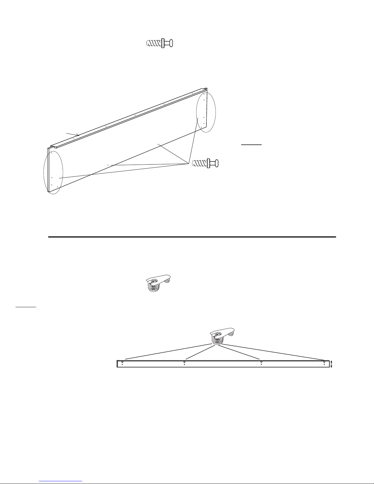
Solid Wood Anchor
support
Hardware needed for next step
x 11
Connecting Bolt
Step 5: Locate the Bridge Board and
Insert 11 Connecting Bolts into the
holes provided. Screw the bolts in until
they tight against the bed part.
Bridge Board Receives 11
Connecting Bolts
Step 6:
and Insert 4 Cam Fittings.
Locate the Bridge Support
Hardware needed for next step
x 4
Cam Fitting
Front Bridge Support
2
3/16”
Page 3
Page 8
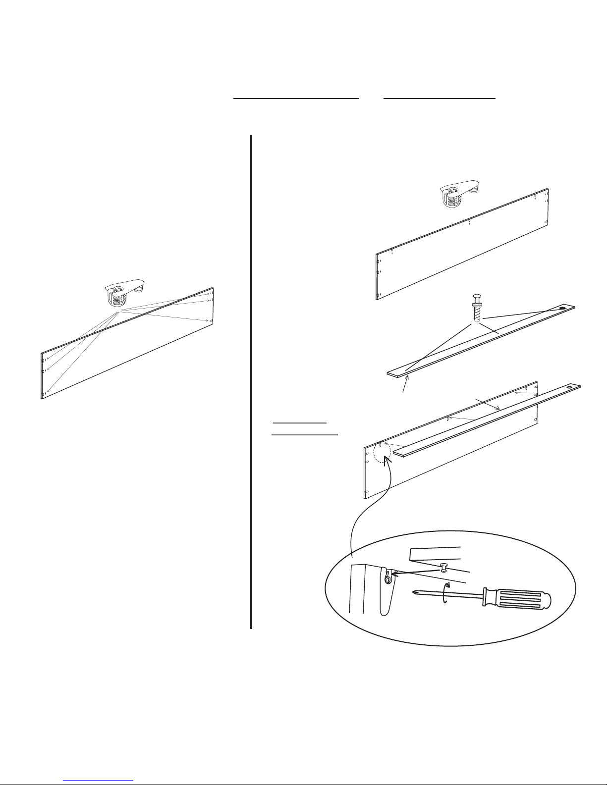
Head Boards have 2 options. Option 1 is Standard depth and Option 2 is Extra depth. Determine which Wallbed you have and then proceed with the correct option below.
OPTION 1
STANDARD DEPTH HEAD BOARD
Insert 6 Cam Fittings in the back
of the Head Board
Insert 9 Cam Fit
tings in the back of
the extra deep Head
Board
Insert 3 Connecting
Bolts in the bottom
of the Head Board
Shelf.
Turn the Head
Board Shelf over
and insert the Con
necting Bolts into
the Cam Fittings
and tighten them
with a Phillips
screw driver.
-
OPTION 2
EXTRA DEPTH HEAD BOARD
Extra depth Head Board shelf
Front
-
Front
Important!
Don’t over
tighten Cam
Fittings a 1/2
turn is suffi
cient.
-
-
Page 4
1/2 turn to right
Page 9
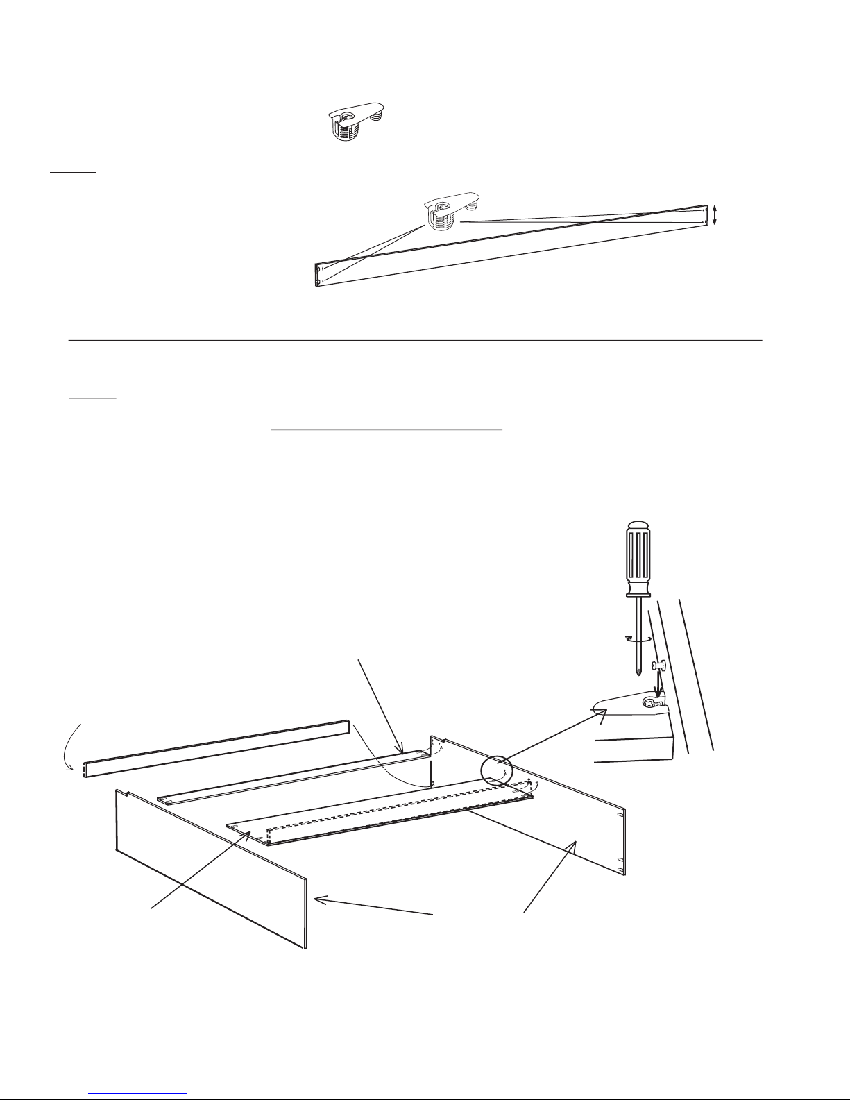
Hardware needed for next step
x 8
Step 7: Locate the 2 Stretcher
Boards (same size) and insert four
Cam Fittings into the back of each
Stretcher.
Cam Fitting
X 2
Step 8:
the wall to which it will be installed. Note the “Front Stretcher” (illustrated
below) should be positioned so the Cam Fittings are at the bottom of the bed.
IMPORTANT! Tighten the cam fittings with a hand screw driver by turning the
Phillips head clockwise 1/2 turn to tight.
HELPFUL HINT: It is easier to tighten the Cam Fittings if the two bed parts are
snug together.
Assemble the Bed Cabinet face down with the bottom of the bed nearer
5”
Illustration 5
Cam fittings on bottom
Bed Bottom
Head Board
Front Stretcher
Rear Stretcher
Optional Head Board Shelf for extra deep
1/2 Turn to tight
Connecting Bolt
Cam Fitting
Side Boards
Page 5
Page 10
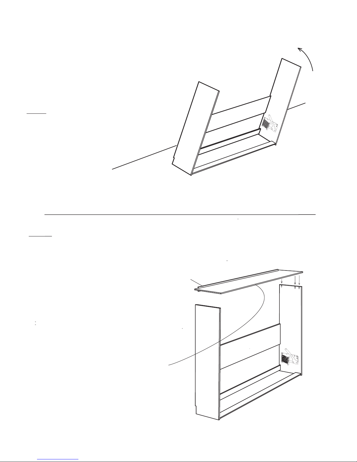
INSTALLATION WALL
Step 9:
2 feet between cabinet and the wall so you
have space to work behind the bed
Stand the bed cabinet up and leave
Step 10:
low. Place it on to the Side Boards and tighten all Cam
Fittings.
Position the Bridge Board as illustrated be
Anchor support
-
Back
Finished edge
Page 6
Page 11
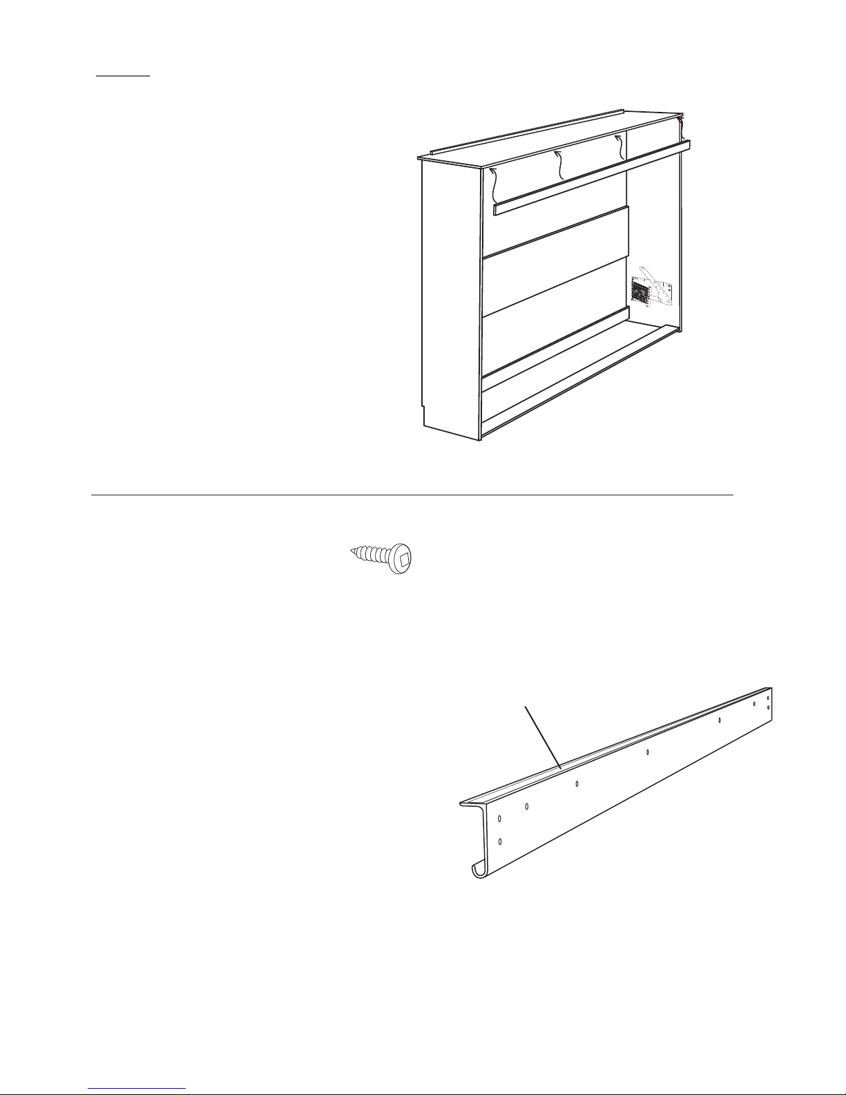
Step 11:
between the Side Boards and on to the Connecting bolts.
Tighten all Cam Fittings.
Locate the Front Bridge Support and insert it
Part and hardware needed for next step
3/4’’ Pan head Screw
Locate the metal Bridge Stiffener from the long white
cardboard box. There are several (5) parts that look
the same as the Stiffener you will identify it from the
others by a length of double stick tape across the top
edge.
X 12
Double stick tape
Metal Bridge Stiffener
Page 7
Page 12
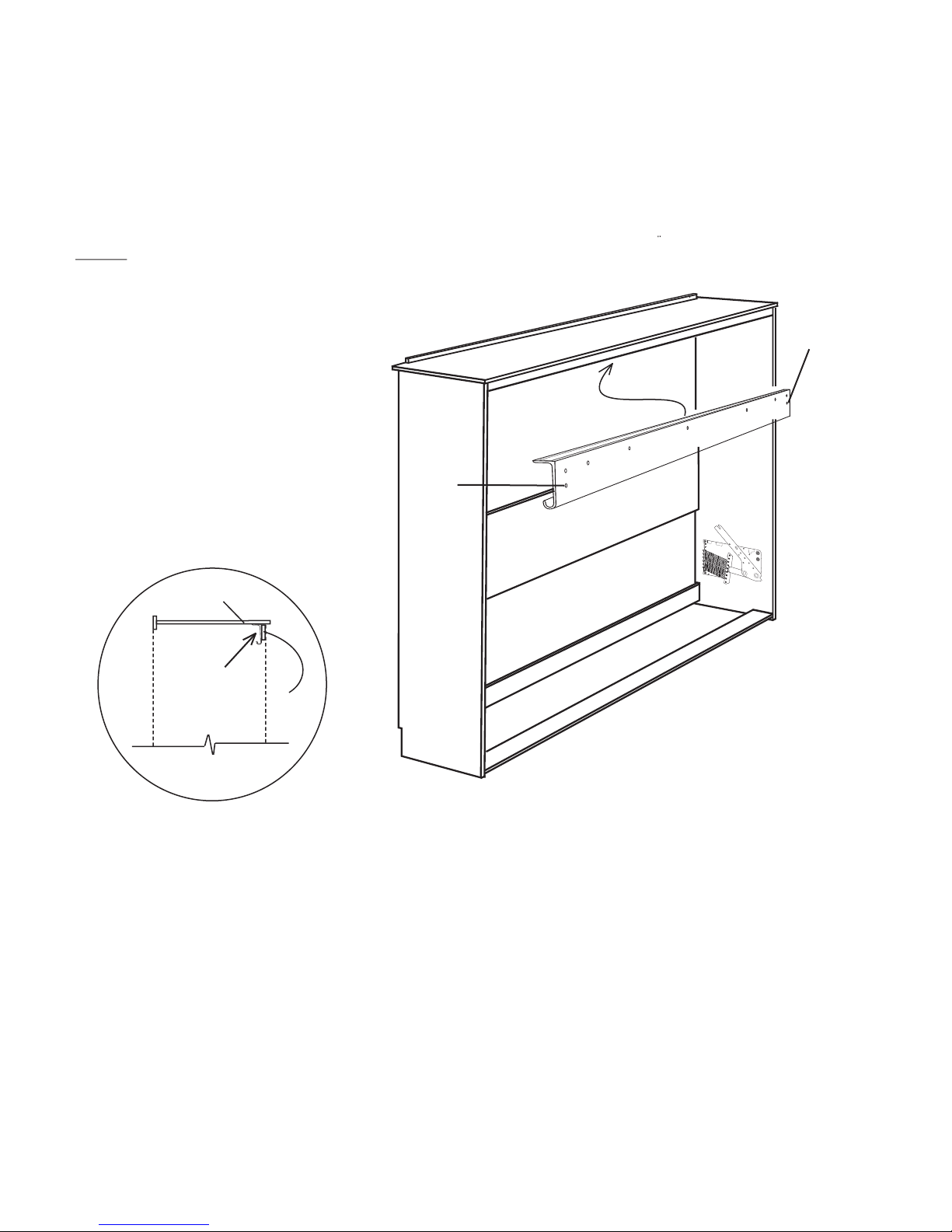
Step 12:
Remove the double stick tape cover
and pass the Bridge Stiffener between the
Side Boards and up behind the Front Bridge
Support. The double stick tape should stick
to the bottom of the Bridge Board. Anchor
the Stiffener to the Front Bridge support and
the Bridge board using 3/4” screws through
holes in the Stiffener.
DO NOT use the lower holes on either end of
the Stiffener as illustrated.
Bridge Board
Bridge Stiffener placement
Front Bridge support
DO NOT USE
THIS HOLE
DO NOT USE
THIS HOLE
Cut away side view
Page 8
Page 13
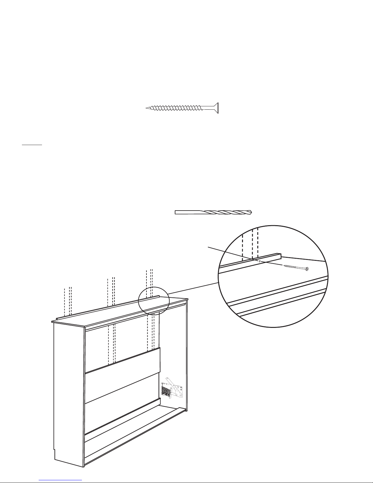
WARNING! THE NEXT STEP MAY REQUIRE PROFESSIONAL HELP.
IF YOUR WALLS ARE NOT TRADITIONAL WOOD FRAMING, YOU MAY NEED TO HIRE A HANDY
MAN OR CONTRACTOR TO HELP IN ANCHORING THE BED TO YOUR WALL. FAILURE TO PROPERLY ANCHOR CABINET COULD CAUSE SEVERE PERSONAL INJURY. CALL TECHNICAL SUPPORT AT 866-725-6401 IF YOU HAVE ANY QUESTIONS.
Hardware needed for next step
x 3
3.5” Wood Screws
Step: 13: Using a Stud Finder locate and mark at least 3 studs in the wall behind the
bed cabinet. Pre drill with a 1/4” drill bit through the Anchor Support Board at the
back of the Bridge Board corresponding with the studs in your wall. Using the 3
1/2” wood screws provided anchor the bed cabinet to the wall through the pre drilled
holes.
IMPORTANT! Bed cabinet requires 3
studs, It is VERY important that the bed
cabinet be anchored securely to the wall.
For technical support call 866-877-7803
toll free.
Pre-drill 1/4” hole
through the Anchor Sup
port board corresponding
with wall studs
-
Stud
Studs in wall
3.5” Wood Screw
Page 9
Page 14
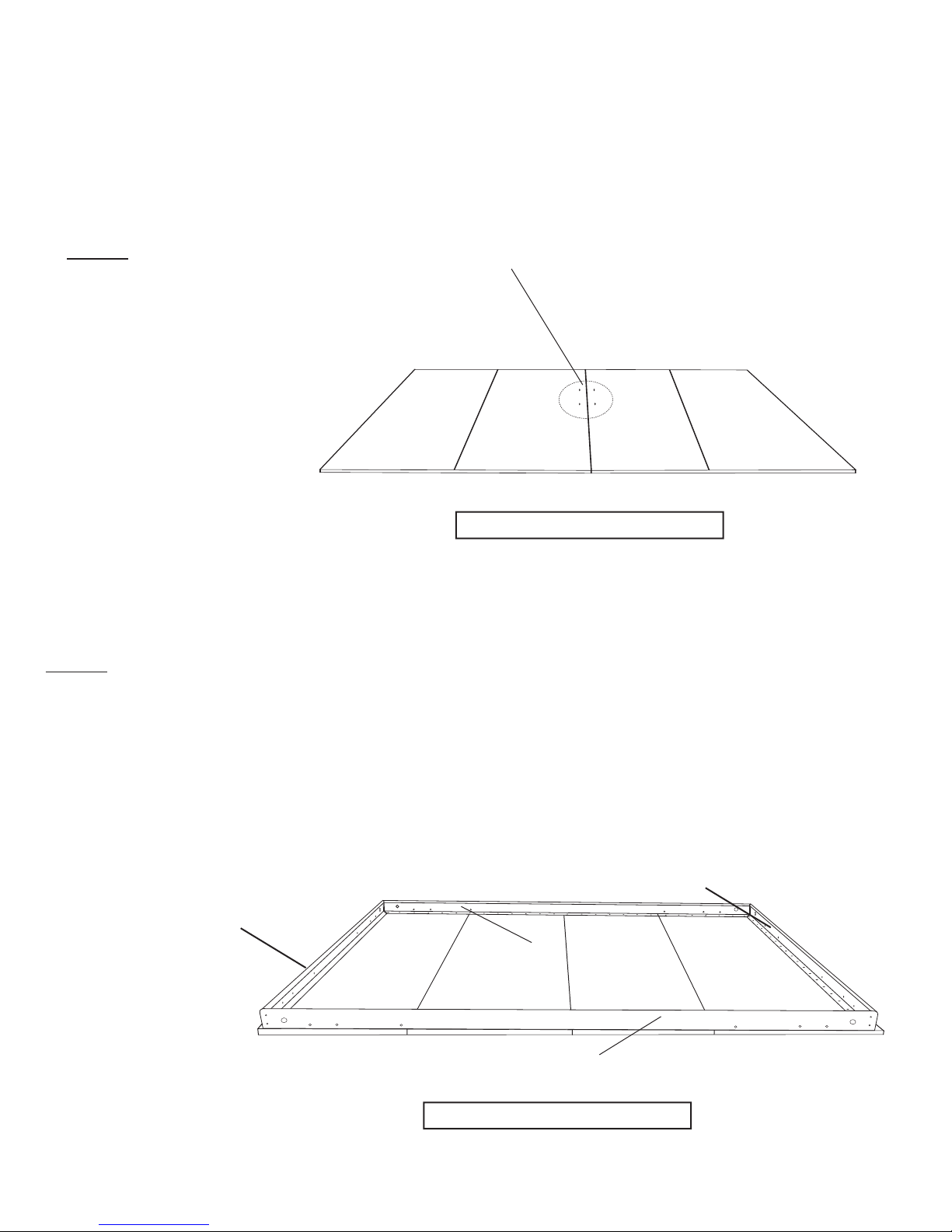
Important note: It is critical to orient the bed face panels and bed rails in the next 5 steps correctly. All of the ren
derings (drawings) in the next 5 steps assume that you are looking away from the wall you just installed the cabinet
against in the previous step. There is a note under each of the renderings indicating “your bed cabinet installed on this
side” which indicates that is where the bed cabinet is in relation to the face panels and rails.
-
Step 14: Locate the Front
Panel(s) and lay them on the
floor face down (finished side).
Position them in front of where
the Bed Cabinet was installed
and leave enough room to work
around them.
HELPFUL HINT: Two of the pan
els have holes drilled for handles.
Those panels should be the middle
two panels with the holes next to
each other and away from the bed
cabinet installed on your wall.
Step 15: Arrange the mattress
rails on the face panels as shown.
Rails are in the long white card
board box.
Holes for handles
-
Your bed cabinet is installed on this side
HELPFUL HINT: Side mount beds
can be slept on in either direction.
The rails referred to as “Head/Foot
rail” can act as either the head or
foot of the bed, depending on which
way a sleeper lies.
Head/Foot rail
Head/Foot rail
Side rail
Bottom rail
Your bed cabinet is installed on this side
Page 10
Page 15
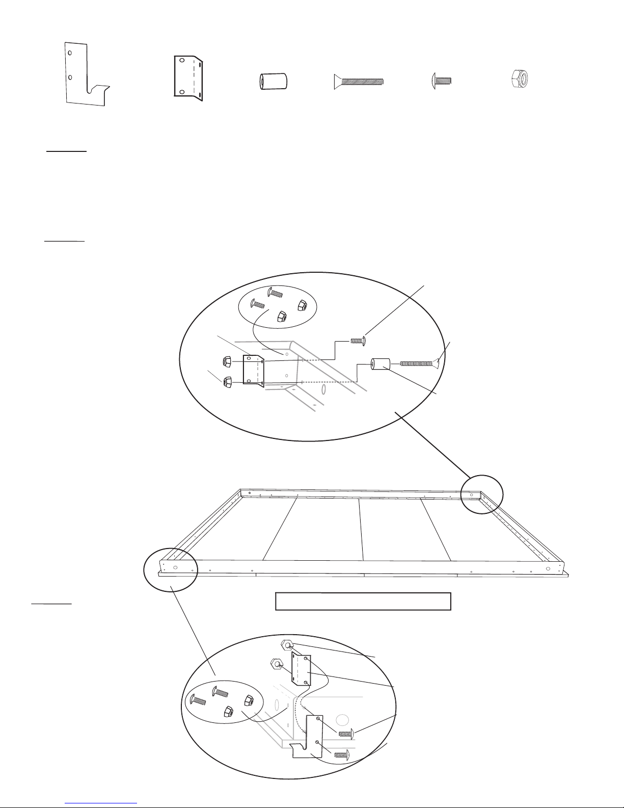
Step 16: From hardware bag 8 locate the hardware shown above. Finger
tighten the hardware as shown in illustration 7 attaching two of the 4 hole
corner brackets on the Head/Foot rail end of the mattress frame. Note the
lower hole on each side rail uses the Leg Stop with the longer screw (3/16” x
1 1/4”). Repeat on the opposite foot rail corner.
3/16” x 1 1/4”
3/16” x 1/2”Leg Stop
3/16” Nylock hex nut
4 hole corner bracket
Spacer Plate
Hardware needed for next 2 steps from Bag #8
x 2
1 Left
1 Right
x 4 x 2 x 2 x 14 x 16
4 hole corner bracket
3/16” Nylock hex nut
Leg stop (black barrel spacer)
3/16” x 1/2” truss head screw (black)
3/16” x 1 1/4” flat head screw (black)
3/16” x 1/2” truss head screw
3/16” Nylock hex nut
4 hole corner bracket
Spacer Plate
(Black)
(Black)
(Black)
Illustration 7
Illustration 8
Page 11
Step 18: Finger tighten
the hardware as shown
in illustration 8 attaching
the 4 hole corner brackets
on the inside of the rails
and the Spacer Plate is
attached on the outside.
Repeat opposite Lower
Rail corner.
Step 17: Once all sides
are finger tight go back to
each corner and align the
corners as they are tightened using either a 3/8”
socket or wrench and a
Phillips screw driver.
Your bed Cabinet installed on this side
Lower Rail
Page 16
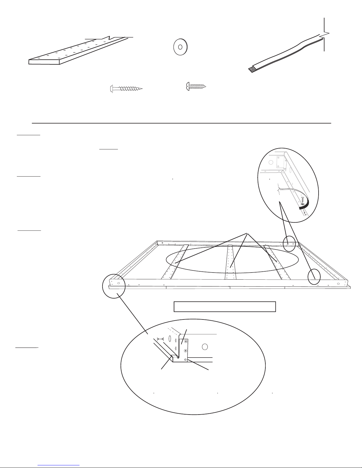
Hardware and parts needed for next steps
x 2
x 3
Wood Mattress Support
3/4” Washer
(Hardware bag #8)
x 160
1 1/4” Square drive
wood screw
3/4” Pan head screw
(Hardware bag #8)
Step 19: Using the Spacer Plates (illustration 9) as a reference on either end of
the lower Bed Frame rail, align the Rail and the wood Face Panels. For proper
alignment the lower rail should be FLUSH with the Face Panels and the Head/
Foot Rails should have a 1” offset top to bottom on both sides. See illustration 9.
Step 20: Using the 3/4” pan head screws secure the
Bed Frame (rails) to the Face Panels using 1 screw in
each corner first ensuring that the frame and panels are
square to each other. Once the Frame is secure insert the
balance of the screws around the Rails.
x 85
Illustration 11
x 1
Velcro Strap
Velcro Strap
Step 21:
evenly over the face panel seams
allowing their ends to over lap the
Upper and Lower Rails (illustration
10). Use the 1 1/4” square drive wood
screws in the holes provided to mend
the face panels together. DO NOT
STRIP SCREWS.
Step 22
holding the mattress in place) about 12”
from the Side Rail of the bed. Put the
hooks part of the strap on one side of
the bed and the loops part of the strap
on the other side. Insure that the hooks
and loops will face each other and
interlock. See Illustration 11
Place the Mattress Supports
Helpful hint: One of the
Mattress Supports may have
an area cut out to allow for the
bed handle holes.
Attach the Velcro Straps (for
;
Flush to edge
of Face Panel
Mattress Supports
Upper rail
Illustration 10
Lower rail
Your bed Cabinet installed on this side
Spacer Plate
1”
Flush to end
of Face Panel
Illustration 9
Page 12
Page 17
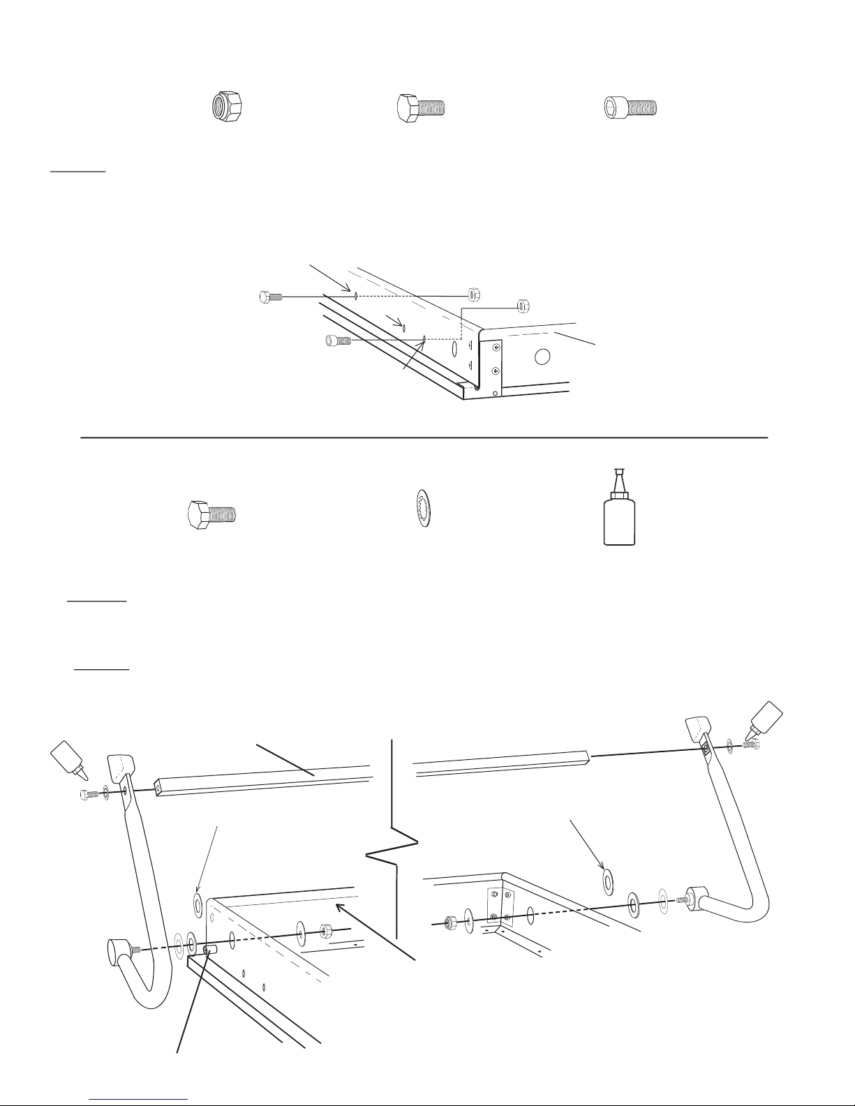
Lower Rail
Bolt hole 1
Bolt hole 3
Bolt hole 2
Step 23: As illustrated below, insert the Allen Key Bolt through bolt hole # 1 and tighten it down securely using a Nylock Nut.
Now insert a 5/16” x 3/4” Hex head bolt through hole # 3 and thread the Nylock nut ONLY UNTIL IT IS FLUSH WITH THE
BOLT END. Bolt hole #2 will be used in a later step.
Hardware needed for next step from hardware bag #7
5/16” Nylock Nut
X 4
X 2
X 2
5/16” x 3/4”
Allen Key Bolt
Page 13
Step 24: Assemble Legs by first removing the nut and the first TWO washers that come pre-installed on the Leg. Leave the
washer with a black edge and the thin plastic washer in place on the leg. Insert the Leg Bolt with the first two washers through the
Head/Foot Rails. DISCARD the thick silver washer then place the black washer and the nut back on the Leg Bolt and tighten.
Step 25: Position the Cross Bar between the Legs. Place 1/2” Star washer on one of the 5/16 X 3/4” Hex Head bolts apply 2
drops of Loc-tite and thread the bolt through the Leg and into the Cross Bar and tighten. Repeat on other side.
Hardware needed for next step from hardware bag #8
X 2
5/16” x 3/4”
X 2
1/2” Star Washer
LOCTITE
Loc-tite
X 1
Discard silver washer
Discard silver washer
Cross Bar
Foot Rail
Leg Stop
LOCTITE
LOCTITE
Page 18
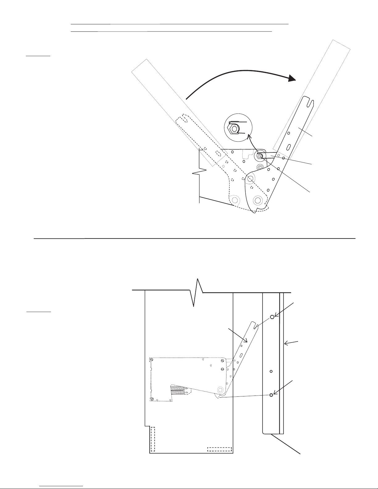
WARNING: There is tremendous force involved in the next step, do not place hands between the front of the side boards and the tension arms as you set the mechanism.
Step 26: Brace one foot against
the front edge of the side board and
using the 13” length of PVC tubing
provided, lever the lift mechanism
tension arm out and down until you
can secure the arm lock to the hexagon nut shown at right. BE SURE
THAT THE LOCK IS SECURED
AGAINST THE HEX NUT BEFORE RELEASING THE TENSION
ON THE LIFT MECHANISM.
Helpful hint: As you start to draw the
tension arm down with one hand, use
the other hand to position the arm lock
on top of the hex nut. Now as the tension arm continues to be pulled down
with both hands, the arm lock will
naturally drop into place around the hex
nut as illustrated.
PVC tubing
PVC tubing
Tension Arm
Arm Lock
Hexagon Nut
IMPORTANT!
the notch at the end of the Tension Arm See illustration below.
Step 27:
on its Lower Rail. Now with you and
your assistant on either side of the
Bed unit lift until the # 3 bolt on the
Bed face unit is a few inches above
the slotted end of the Tension Arm on
both sides. Gently lower the Bed face
unit between the Tension Arms and
seat the # 3 bolt into the slot at the
end of the Tension Arms. Now start
pulling the bed face unit down and
away from the Bed Cabinet the Allen
Key bolt head will seat into the notch
at the lower end of the Tension Arms.
Lower the bed unit down and pull
the Legs down so that they are on the
floor. Someone will need to hold the
bed unit down as it will want to rise.
Stand the Bed face unit up
As instructed in step 23, Bolt #3 should be loose enough to slip into
#3 Bolt head
Tension Arm
Bed Front
Allen Key bolt head
Lower Rail
Page 14
Page 19
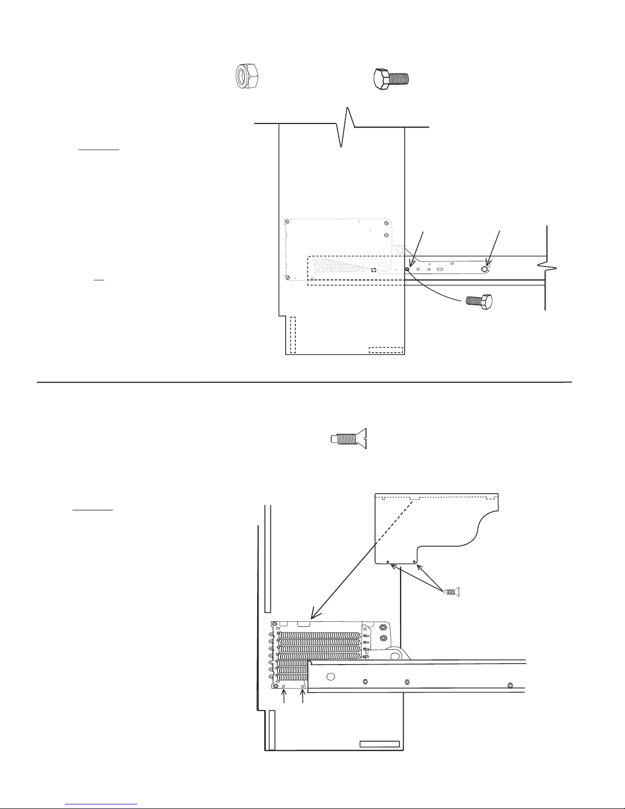
Hardware needed for next step from hardware bag #7
5/16” Nylock Nut
Step 28: Insert a 5/16” X 3/4” Hex
bolt through hole #2 and tighten a 5/16”
Nylock nut onto the bolt. Now tighten
the nut and bolt in hole #3.
Repeat step 28 on the other side of the
bed unit.
WARNING!
the bolts in step 28 could result
and tighten
severe personal injury
in
damage to the lift mechanism. Lift mechanism
damage caused by missing or loose hardware
is not covered by warranty.
all
Failure to insert
or
X 2
5/16” x 3/4”
X 2
Hole #2
Hole #3
Hardware needed for next step from hardware bag #7
Step 29:
over the Mechanism so that the tabs on
the cover fit into the notches provided.
Line up the holes with the threaded
supports and insert two 4mm Flathead
screws.
Repeat step 29 on the other Mechanism.
Slip the Mechanism Cover
x 4
4mm x 1/4” Flathead Slot Machine screw
Black Plastic Mechanism cover
Head Board
Threaded Mechanism
Cover Supports
Page 15
Page 20
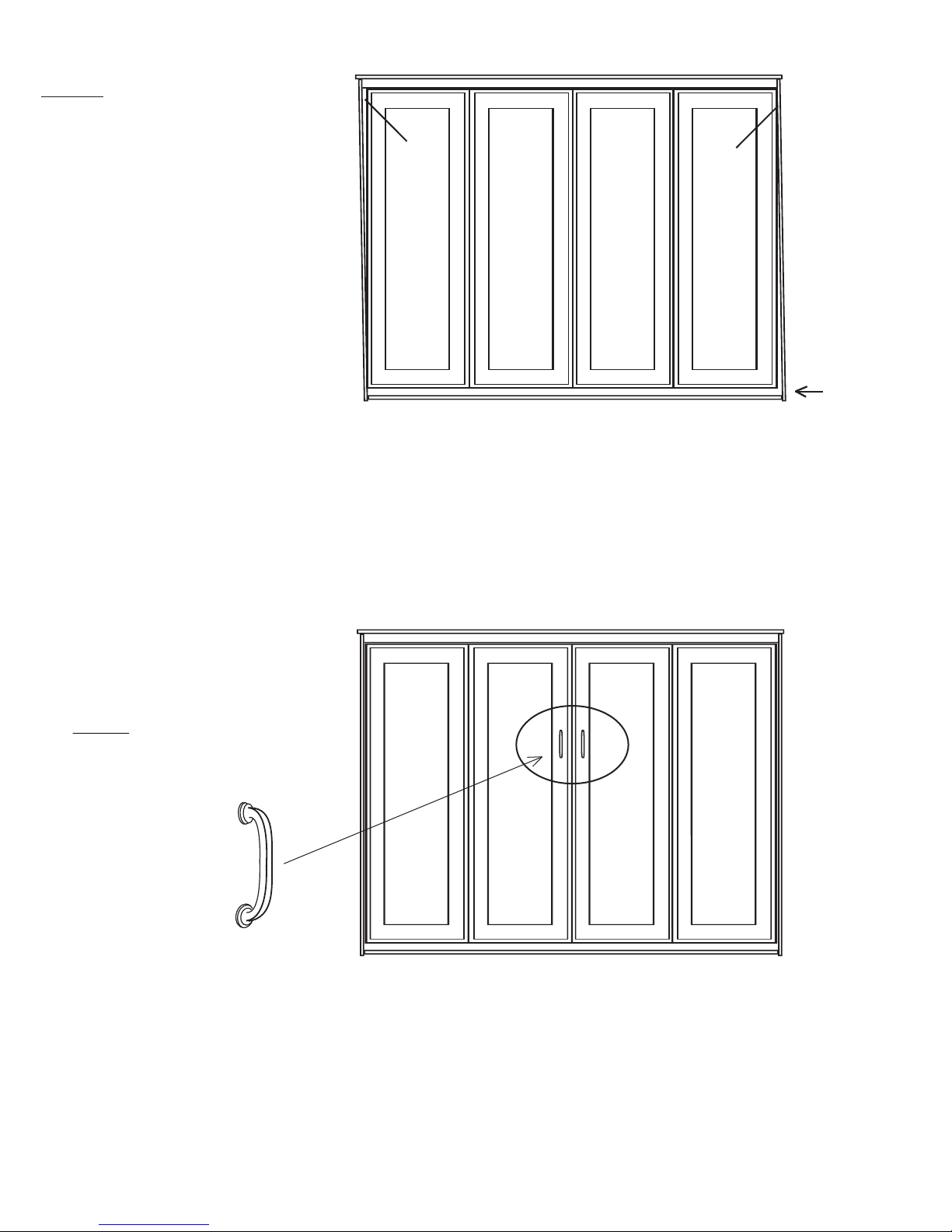
Step 30: When the bed is closed check to
see if the gap on either side is the same. If
it looks right skip this step. If the gap is not
right, meaning that the Bed Box is too close
to the side board or even touching it at the
top on one side it will need to be adjusted.
The procedure will require the bottom of
the bed to be moved slightly to the left or
right depending on which top corner is too
close. If the bed is too close on the top
right side for instance, the right side (bottom) will need to be slid to the left slightly.
Have one person push the bed at the bottom
with his feet while the second person pulls
at the opposite bottom side.
Gap
Gap
Push bed
over at the
bottom to
align
Step 31
Handles provided using the pre
drilled holes in the two center
panels
: Attach the Bed
Page 16
 Loading...