

Page 1
Preliminary edition rev. 1.01 March 6, 2006
please report errors to [email protected]
Wild Hare R/C
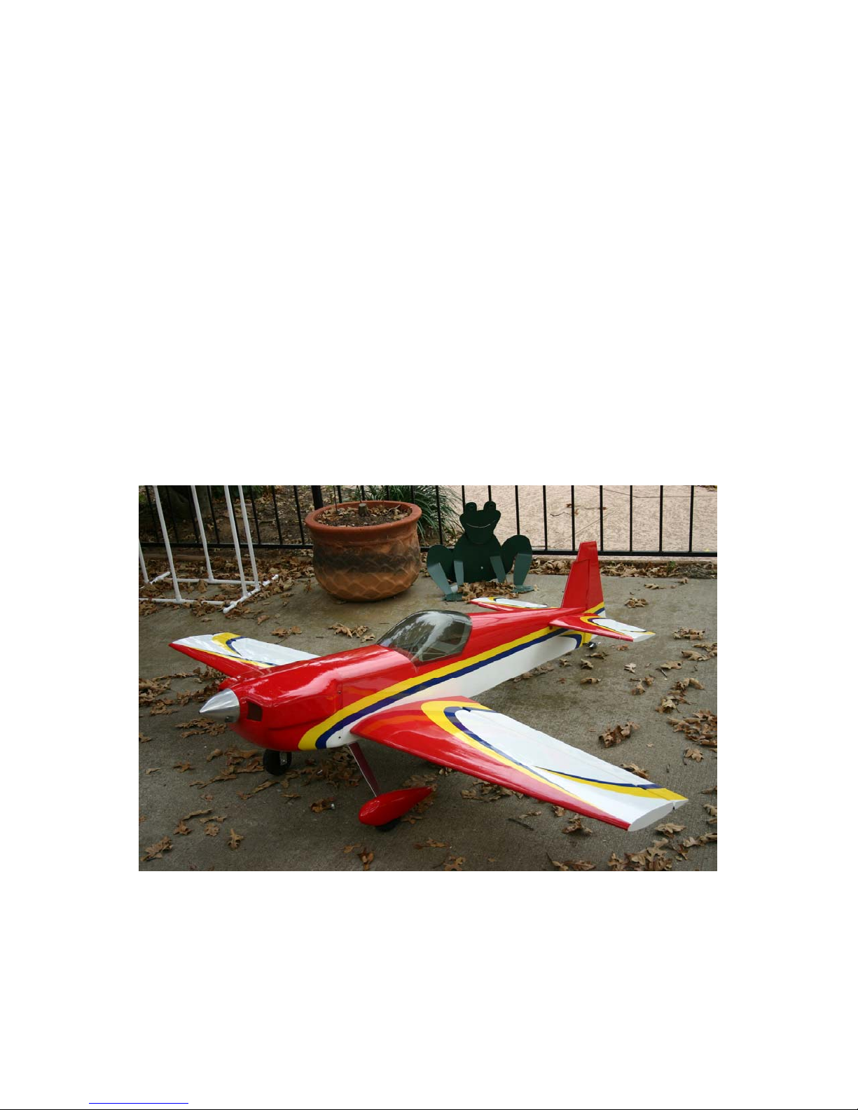
Cap 232 28% and 31%
Assembly Manual
For assistance contact Wild Hare R/C
6508 Cardinal Drive, Flower Mound Texas 75022
817-430-0107 Fax 817-490-1279
Email [email protected]
Copyright © 2006 by Wild Hare Hobbies, Inc. All rights reserved.
Page 2

Warranty Information
Wild Hare R/C, division of Wild Hare Hobbies, Inc. guarantees this kit
to be free of defects in both material and workmanship at the time of
purchase. This warranty does not cover any components damaged by
use or modification. In no case shall Wild Hare Hobbies, Inc. liabil-
ity exceed the original cost of the purchased kit. Further Wild Hare
Hobbies Inc, reserves the right to change or modify this warranty without notice. This warranty extends only to the original purchase.
In that Wild Hare has no control over final assembly or materials used
in final assembly, no liability shall be assumed or accepted for any
damage resulting from the use by user of the final user assembled product. By the act of using the user assembled product, the user accepts all
resulting liability.
If the buyer is not prepared to accept the liability associated with the
use of this product, the buyer is advised to return this kit immediately in
new and unused condition to the place of purchase.
While this kit has been flight tested to exceed normal use, if the plane
will be used for extremely high stress flying such as racing the modeler
is responsible for taking steps to reinforce the high stress points.
Read through this manual before starting construction. It
contains important warnings and instructions concerning
the assembly and use of this model.
Warning. This is not a toy. If not properly controlled it can cause injury or death and property
damage.
Page 3

Specifications
Wingspan 85 inches (91 inches optional)
Length 77 inches tail to cowl face
Wing Area 1350 sq. inches (1520 sq. inches on 91” wings)
Weight 16-18 lbs . (18-21 lbs 91” version)
Recommended engine (85”) 50 to 62 cc gasoline engine
(91”) 58 to 80cc gasoline engine
weight not to exceed 5 lbs.
Additional equipment required
Computer Radio with at least 8 channels strongly recommended
2 Elevator servos minimum 120 oz/in. of torque each e.g. Hitec HS5645 or 5945
2 aileron servos, total torque required not less than 120 oz./in. per wing.
Rudder servo(s) at least 180 oz./in. (see text) e.g. Hitec 5955TG or JR 8611a
Throttle/choke servo standard BB servo such as Hitec 425
Radio operated engine kill switch or servo operated choke strongly suggested
Single or dual radio battery packs at least 2100 mah total, preferably high current output cells.
Total capacity will be based on how much flight time is required.
Switch[es] for receiver batteries 2 or 3
Miscellaneous servo extensions. 2x24”, 4x12”, 2x18” typical
The kit includes lightweight foam wheels and axles. These are light duty and may not last more
than a few flights, stronger wheels and axles are in our hardware kit. It also includes a tailwheel
assembly, wing tube (carbon fiber tube on 91” planes) and miscellaneous small hardware for
mounting the cowl, wings, stabs, and landing gear.
Please remember, this is a big airplane with high stresses on the controls. You must use high
performance servos, pushrods, linkages, horns, etc. Flexing in linkage or loose hinges can
and will cause flutter of the control surfaces which will destroy the airplane in just a few
seconds.
Metal gear servos are required. Proper installation of hinges
is critical.
Page 4

Optional Accessories
Wild Hare R/C makes available accessories that can enhance this kit’s usefulness.
Hardware kit. Your kit has some basic hardware, but our hardware kit includes
all the things you need to assemble the Cap 232 except for engine, muffler, spinner, glue, prop, and electronics. The hardware kit is from US suppliers and all the
hardware has been tested to be completely compatible with our kits. it contains;
3 sets of HD control horns (based on Dubro parts)
6 Sullivan golden clevises with retainer clips
Carbon fiber pushrod materials to make pushrods as explained in this manual.
Wild Hare pull-pull kit for rudder
3 1/2” Dubro or Sullivan wheels and 3/16” axles and 4 wheel collars..
24 oz. gas tank (or smaller if requested), Dubro plus tygon line, tee, and fuel dot
2-56 throttle and choke pushrods with nylon clevises
Many miscellaneous small parts such as nuts, washers, horns, springs, etc.
Spinner. The Cap 232 requires a 4” spinner. Wild Hare normally keeps Dave
Brown Vortec spinners in stock, they are cut to fit a large prop such as a 22-10
Menz, and are normally available drilled for a DA-50 and a 6 bolt pattern as is
used on 3w, Evolution, etc.
Switches. The Cap 232 has holes laser cut in the fuse sides to accept the Maxx
products charge-jack switch, a very nice way to switch your receiver and ignition
batteries.
Servos. Wild Hare sells servos from Hitec and JR. We have flown the planes with
servos ranging from the economical Hitec 645 to the JR 8611 and Hitec
5945/5955. We have found that better servos really do make a plane fly better, and
we recommend that you use the best servos that you can afford no matter where
you buy them.
Carbon-fiber wing tube is stronger and lighter than the supplied aluminum tube.
The CF tube is standard on the 91” planes.
Pilot and instrument panel dresses the plane up and is required to avoid penalty
in in upper IMAC classes.
Page 5

Table of Contents
Steps Subject
1 Open and inspect everything
2 Mount the engine
3 Hinge the control surfaces
4 Install the control horns
5 Mount the hatch and canopy
6 Mount the horizontal stabilizers
7 Install the servos
8 Install the landing gear
9 Install a fuel tank and fuel system**
10 Mount the radio equipment**
11 Hook up the engine control linkage**
12 Mount the wings
13 Check and adjust balance
14 Control throw adjustment
** These Items require user supplied materials and creativity. These steps as-
sume that the user will be installing mounts, retainers, and other assemblies to
suit his particular building style. For example no servo mount is supplied for
the throttle, we have no way of knowing what type of engine you will use or
what is the best location for the throttle servo.
If you need advice on any of this, call us or email [email protected] and
we’ll be happy to try to try to answer your questions.
Page 6

28% Cap 232 Assembly Manual
Step 1. Open and inspect everything
This section should be fairly self explanatory.
In the large box you should have a fuselage with hatch., wing tube and stab tube, the elevator/stab assemblies, the rudder, cowl, wheel pants, canopy, landing gear and packages with
the tail wheel assembly miscellaneous nuts and bolts. The hinges are installed in the elevators and ailerons, but they are not glued, you have to do that. The hinges for the rudder are
packed separately. We have had good luck with Pro-bond Ultimate and Gorilla glue, both of
which are glues that expand as they dry cure and fill the voids in the hinges and their sockets.
Check everything for shipping damage and/or manufacturing defects. If there is a problem,
report it to us NOW, not after you start building the plane. SAVE ALL PACKAGING
UNTIL YOU ARE SURE THERE IS NO DAMAGE< PACKAGING IS REQUIRED
FOR ANY DAMAGE CLAIM.
Before proceeding to any assembly, now is a good time to go over the whole plane and fix
any cosmetic flaws. Some cosmetic flaws are to be expected, this fact is reflected in the
price.
Known issues and improvements
There are a few areas where, at this unassembled stage, you can improve the final results of
your assembly project. There are many items that cannot be addressed on the assembly line
due to cost and possibly because not every improvement would be welcomed by every
builder. Here are a few items that have come up over time.
First, check the fit of wings and stabs to the fuse. Now is the time to report any problems.
Go over the covering with a heat gun or iron. The covering tends to get loose over time
and with changes in temperature and humidity. It may have come out of the box with wrinkles, I can assure you it did not go into the box that way. Also, In particular use a covering
iron to iron down all covering edges, this is an area where production line built airplanes
always need help. Pay close attention to the leading edges of the wings and stabs, be sure
there are no forward facing seams. A piece of transparent packing tape can be a big help to
seal along the LE if there is an exposed seam.
Page 7

Clean out the hinge holes. Without removing any wood, use a very sharp X-acto knife and remove any covering that may have been pushed into the hinge holes. It is very important that the
glue sticks to the wood and not to the covering. See the section on hinging before you do this.
Hardening holes. The fuselage sides on this plane are made of balsa which in certain areas is
doubled by lite ply. The control horn hard points are made of a soft pine or fir type wood. Any
soft wood like this will benefit from hardening with thin CA. It’s a good idea whenever you
drill a hole that must accept a wood screw or the hinge screws to put a drop (or more) of thin
CA into the hole and then if necessary re-drill the hole. The CA will wick into the wood and
harden it, adding strength in that area.
Canopy Hold Down — The canopy hatch as supplied is held on with 4-40 socket head screws
which screw into blind nuts that are pre-installed. We found in testing that these tend to unscrew when subjected to vibration. The most reliable fix for this is to use a nylon screw
threaded directly into the wood. The text covers how to do this.
Firewall reinforcement — First, be sure the firewall is properly glued, this is one weak spot of
assembly line construction.
Set the fuselage on its side on an angle with the nose down. Put something under it, glue may
drip. Dribble thin CA into the joint between the firewall and the motorbox side. Let it dry, then
repeat until the wood will no longer absorb any Ca. Turn the fuse over and repeat.
Next, do this if you are using a heavier engine. You will find in the kit a piece of aircraft ply the
same size as the rear surface of the engine mount firewall. This ply should be laminated to the
back of the firewall with good quality epoxy to stiffen the firewall for use with larger/heavier
engines. After installing the ply laminate it’s a good idea to install triangle stock in the corners
where the firewall meets the sides, also with epoxy.
If using a light engine (da-50, zdz-50, Brison 3.2) the triangle stock in the corners is still a
good idea. On the 85” planes if you find that the plane is tail heavy when you balance it reinforcing the firewall is a good use of any added weight.
Re-glue servo trays — One of the areas that the factory can do better is gluing the servo trays.
You should use some thin CA to securely glue these into the fuse and wings. Servo trays are
under a lot of stress, be sure they are secure.
Page 8

28% Cap 232 Assembly Manual
Step 2. Engine mounting
The first thing to do, before anything else goes in the fuselage, is to get the engine mounted and
aligned with the cowl. Here’s how I have done it. This is the hardest and most time consuming
step in building this plane. If you can do this everything else should be easy. Do this first before
you hinge the rudder.
Note that the firewall already has a proper amount of right thrust built in, do not use any other
offsets. When you shim the engine out from the firewall use shims of equal thickness on all 4
corners so that you do not introduce any other thrust angles.
With no cowl or hatch on the fuse find a place in your workshop
where you can stand the fuselage up on its tail so that the motor
mount is pointing at the ceiling. Secure the fuse so it stands like
that and won’t fall over. I wrap masking tape around it and tape
it to the side of the workbench.
Set the engine on it’s rear radial mount (assuming it has one) on
the motor mount firewall so the crankshaft is pointing up at the
ceiling. Some single cylinder engines will sit nicely on their motor mount plate on the firewall, others have too much weight in
the cylinder and will fall over. If yours falls you will need some
method of keeping the engine sitting on its mounting lugs without falling over. In the photo at the right we are showing an engine with its cylinder removed, we do not suggest this method
but it sure does make it easy.
A simpler solution to the problem is to put good quality double sided tape on the firewall approximately where the mounting lugs will sit. The sticky surface will hold the engine in place
and keep it from tipping over.
When using the Evolution 58 if you do not have standoffs already made you will need to cut 4
pieces of dowel 2 inches long out of 3/4” oak available at Home Depot. Use a sheet metal screw
to attach the dowels to the mount lugs to use during the alignment process.
Now mount the cowl using the supplied screws and washers. The hardware kit has rubber
backed bonded washers to keep the cowl screws from vibrating loose. If you are using a single
cylinder engine it may be necessary to cut out the cowling to clear the cylinder to mount the
cowl, but most singles will fit in the Cap cowl by just removing the spark plug. Cut a little bit at
a time rechecking clearance until the cowl will fit over and mount on the cowl.
Page 9
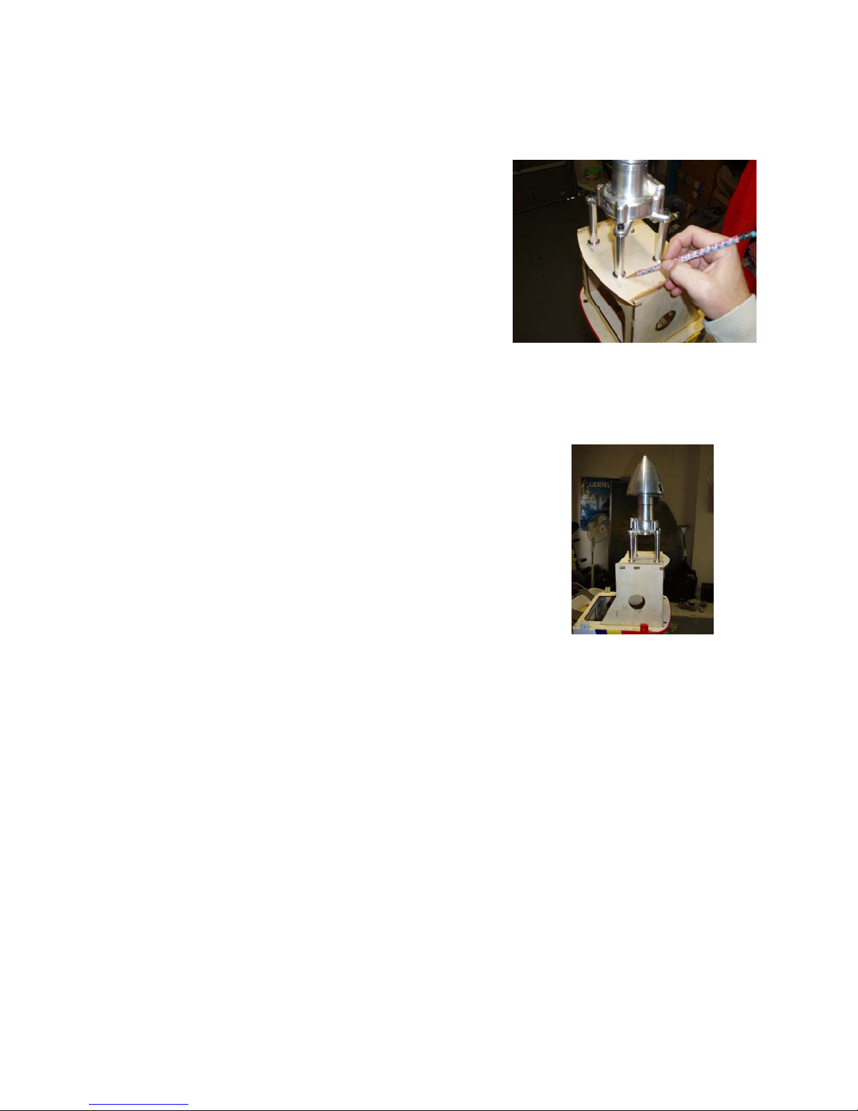
Mount the cowl using the supplied screws and washers. Place your spinner back plate over the
crankshaft or prop bolt so that it is centered. You can now just move the engine around to get
the spinner back plate centered on the cowl face.
Once the spinner back plate and engine are in the right position, remove the cowl and mark the location where the
engine is standing before removing it. You can now drill
the engine’s actual mounting holes in the firewall.
The final step is to install the engine using either blind nuts
behind the firewall or, as we show with a DA-50, bolts
through the back of the firewall into the standoffs supplied
with the engine or which you have made or bought elsewhere. Fine adjust the engine spacing so
that the spinner back plate fits perfectly by leaving the standoffs a little short and using washers
to set the final spacing.. Remember that the firewall is already set with proper thrust angles,
any drilling must be square to the firewall and not parallel with the fuselage line.
Like I said, the rest is very easy.
Page 10
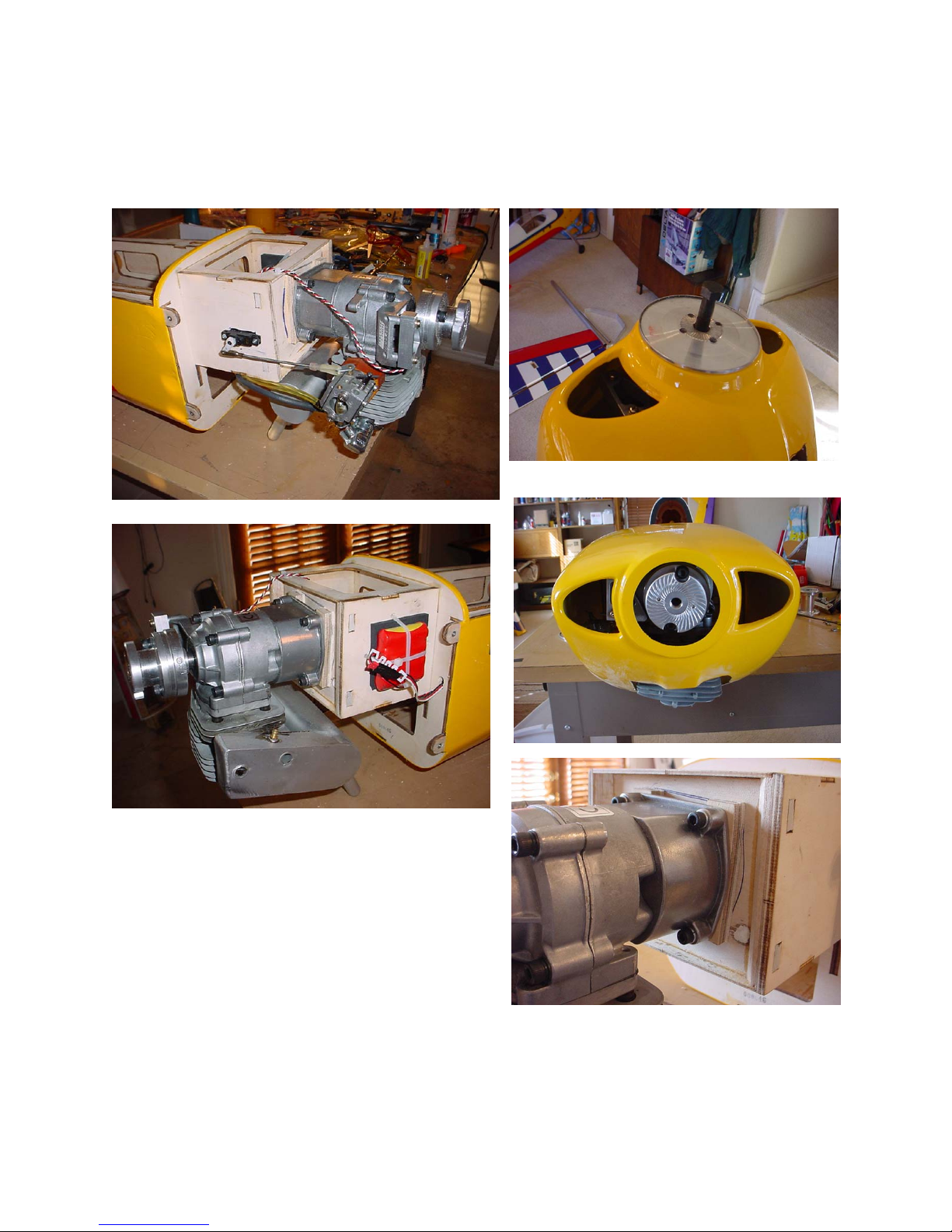
The photos on this page show a different airplane but the idea is the same.
Page 11
28% Cap 232 Assembly Manual
Step 3. Hinging the control surfaces
Hinging is a very simple matter. We recommend that you hinge all the control surfaces in two
steps allowing the glue to dry between steps.
Before you start gluing anything, test fit each control surface. Aileron to wing, elevator to stabilizer, rudder to fin/fuse, with the hinges in place. Make sure the hinges go in the holes smoothly
and that there is ample room for the hinge “knuckle” so there is no large gap between surfaces.
The hinge lines are beveled. The point of the bevel should be at the center of the hinge pin, this
assures that the hinges are aligned and centered on the hinge line.
You may want some extra control surface throw for heavy duty 3d. To do this leave a small gap
between the control surfaces to allow more deflection. If you do this you should probably seal
the gap with some matching or clear covering material.
Once you are certain that they all go together smoothly, take one surface and remove the
hinges. Glue the hinges into the holes securely using the glue you prefer. I have had good success with Gorilla Glue (available at any Home Depot) because when drying it foams up
slightly and fills the gaps between the hinge and the mounting hole. Check hinge operation
every few minutes, as the glues sets wipe off any excess that oozes from the glue joint.
Using Gorilla glue here is the procedure for hinging.
1. Iron down the covering on the hinge line so there are no loose edges or seams.
2. Put a piece of 2” wide masking tape across each hinge hole so
the hole is centered in the tape.
3. With a sharp razor knife cut away the tape and covering material from each hole so only wood is exposed.
4. Again using your sharp razor knife cut the tape along the
pointed bevel edge so the tape can later be pulled away with the
hinges installed.
5. Pour some Gorilla glue in a cup. With a toothpick (break off the
pointed end) pick up as much glue as you can get to stick to a
1” section of the toothpick and then swab the inside of 1 hinge
hole until the sides are generously covered with the glue.
6. Insert the hinges until the point of the bevel is centered on the
hinge pin. Make sure the hinges can be worked, and that the
bent hinge is perpendicular to the edge (see picture).
7. Allow the glue to set for at least two hours, but keep an eye on
it for the first 15 to 30 minutes to be sure the glue’s foaming
Page 12

action does not push one of the hinges out of the hole.
8. After the glue is set flex the hinges back and forth to break
away any glue that might have stuck to the knuckle.
9. Repeat steps 1 through 5 on the other surface
10. Join the two surfaces by pushing the exposed hinge ends into
the other surfaces.
11. Allow to dry for 4 hours.
12. At this point you should be able to flex the surface back and
forth. You can now remove the masking tape.
13. Clean off any residue from the hinge and put a drop of 3-in-1 oil on the knuckle. The surface should move freely.
Page 13

28% Cap 232 Assembly Manual
Step 4. Mounting the hatch and canopy
The hatch mounts to the fuselage by two tabs on each side that are attached at the rear of the
hatch. The holes for mounting the hatch are pre-drilled and 4-40 blind nuts are already installed, you only need to find the hole under the covering and open it up with a knife or a hot
nail.
I have had my share of problems with those small screws falling out from vibration. I have
found that replacing the 4-40 screw with a 1/4”-20 nylon screw (included in the hardware
kit) is much more secure. To do this you will need to;
Remove the blind nut and redrill the hole in the hatch
tab to 3/16”
Tap the 3/16” hole with a 1/4”-20 tap
Harden the threads with thin CA
Re-tap the threads after the CA is fully hardened
Drill the hole in the fuse side out to 1/4”
You can paint a 1/4” nylon screw head to match your
plane’s covering.
Trim the canopy to fit the hatch. Leave a small lip in the front, it makes the attachment more
secure. Attach the canopy with whatever is your favorite method. Some people use tape,
some glue the canopy down, some use small screws. This is up to you. If you use small
screws add some hard wood such as 1/16” ply to back up the balsa wood of the hatch, or
harden the balsa with thin CA.
Page 14
28% Cap 232 Assembly Manual
Step 5. Install horizontal stabilizer
This step is easy.
Trim the covering around the holes in the fuse for the stab spar tube and the two retaining
screw holes on each side. You should also cut away the covering over the holes for the elevator servos, but don’t cut out the rudder servo covering yet.
Slide the spar through the fuse, and slide the stabilizers onto the tubes from each side.
Retain the stab to the fuse with two 4-40 screws, washers and lock washers supplied with the
kit. I advise you to use washers and lock washers or a little red RTV or blue loctite on the
threads. Don’t use a lot, and don’t use red loctite, or you won’t be able to get the screws out
without tearing out the blind nut.
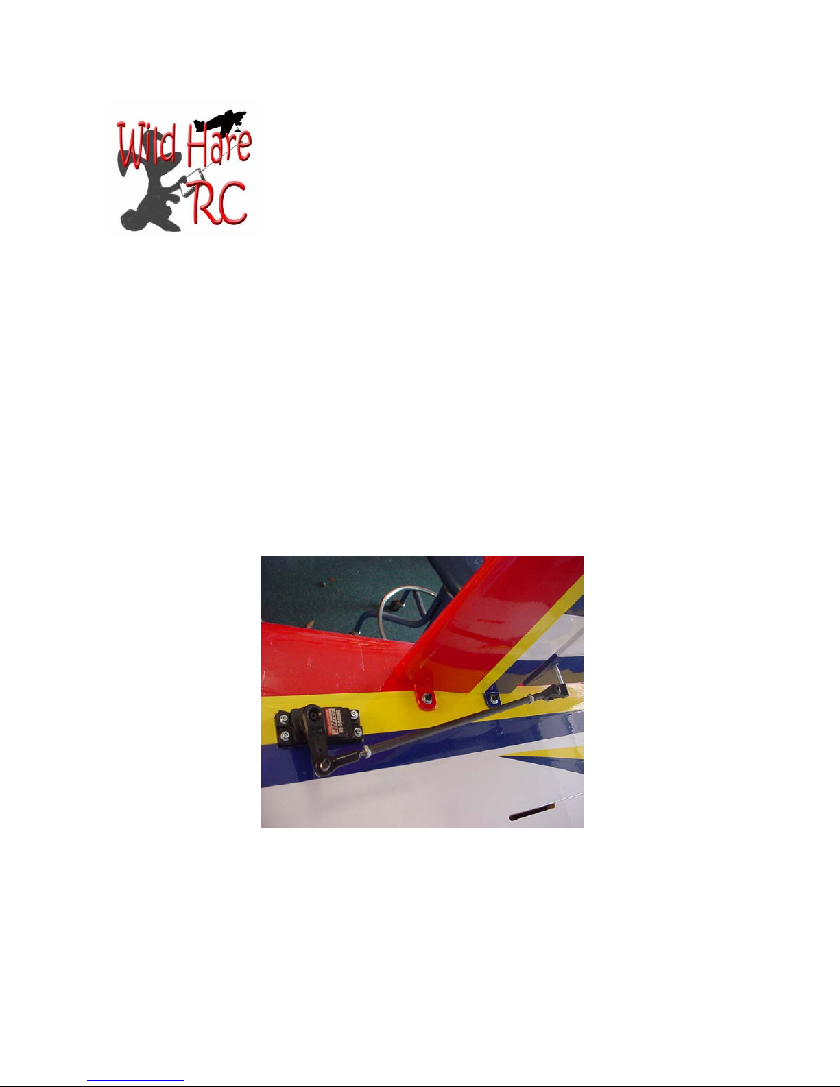
The assembled h-stab with controls is shown below.
Page 15

28% Cap 232 Assembly Manual
Step 6. Install control horns on all surfaces
We recommend Dubro #866 or similar control horns with a 8-32 screw used for the horn. In
our hardware kit we supply a version of this horn set with parts for one complete airplane.
You should decide whether you care if the screw head shows on the upper surface. The hard
points are already pilot drilled, but need to be made larger for the 8-32 stud. I have found
that grinding a small flat on one side of the tip of the 8-32 stud makes it thread into the hard
point more easily.
IMPORTANT NOTE: Do not drill the hardpoints larger than 9/64. The screws must
thread snugly into the hardpoints. If you drill it larger the screw can wobble in the hole
and allow the control surface to flutter with disastrous results.
You should harden the hole after drilling with thin CA.
If you don’t care about the screw head showing, drill all the way through the hard point in
the aileron and elevator with a 9/64 drill. Also drill the hard point in the rudder with the 9/64
drill. Countersink the drilled holes in elevators and ailerons on the top.
On ailerons and elevators install the 8-32 stud from the top, screw it all the way in until it is
snug. Install the rest of the horn assembly from the bottom.
Or;
Another way to do it does not allow anything to show on top. Very carefully and slowly
drill from the bottom side with a 9/64 drill, following the pilot hole so you don’t change the
angle. I use a hex drive quick change bit and put it in my power screwdriver which turns
slowly and is easy to handle. Pull the bit out every 1/8” or so and blow out the shavings.
While drilling observe the top surface of the hardpoint visually. When the drill reaches the
covering on top you should be able to see it bulge before the covering is pierced. As soon as
you see it, stop drilling and withdraw the drill, blow out all the shavings.
Now take your 8-32 stud and thread it into the hole from the bottom. Screw it in by hand or
with a power screwdriver, again observing the other end, until you can see the tip of the
screw through the covering.
Now, cut off the head of the stud/screw and thread the rest of the hardware onto the screw.
Page 16
Here’s a tip. When you cut the head off with your Dremel, it will be hot. Don’t let it fall on
your legs or on the covering or it will burn through the covering (or your skin or pants).
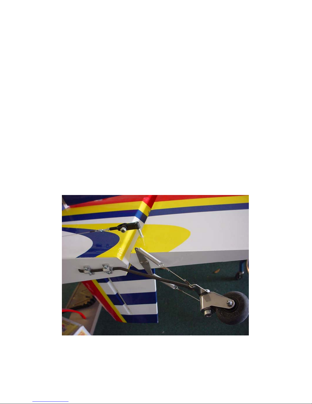
Rudder tiller;
After the upper hardpoint has been drilled through with a 9/64 drill, install the tiller bar so
that it is showing the same amount of threads on each side of the rudder. Once the stud is
installed cut the head off with your Dremel. The stud should be tight in the hole, if it is loose
you should add a nut and washer on each side to secure the stud.
After the tiller bar is installed, if you need to adjust the position you can do this without
damaging it by double-nutting two 8-32 nuts and use a wrench to turn the stud into the hardpoint.
Now install the horns exactly the same distance from the rudder surface. If using the DuBro
horn set for this you should re-drill the horn in a location that is even with the hinge center
line. Both horns should be drilled at the same point. Then trim the excess from the horn leaving at least 1/8” of material at the end.
Page 17

28% Cap 232 Assembly Manual
Step 7. Installing the servos
1. Elevator servos.
Trim away the covering from the rear sides of the fuselage to expose the two servo trays. Attach a servo extension to the servo cord long enough to reach the receiver, and tie this servo
connector together with dental floss or whatever you prefer.
Slide the extension through the servo hole and fish the end through the fuse with a piece of
wire with a hook or whatever you want to use. Servos should be secured with all screws.
There are two fuselage formers that have lightening holes in them. If you run the extensions
through these holes it keeps the wires from flopping around in flight.
2. Aileron servos.
In the 91” wings there is a servo wire tunnel through the wing that touches the servo tray.
You can use a piece of wire with a hook to fish through the hole and pull the servo pigtail
through. Be sure the extension is long enough to reach the receiver. Also be sure the servo
extension is securely attached to the servo lead. If you bought our hardware kit there are
small plastic retainer clips included for this purpose.
The 85” wings are open bay, simply cut away the covering around the servo tray and install
the servo and extension.
I have found that gluing a servo extension to the side of the
fuse makes a handy place to plug in the aileron on each
side. It must be done where there is an opening in the root
rib. If you prefer, there are two locations provided to mount
an MPI “Double link” but this is simpler and less expensive
when using only 1 wing servo per side.
3. Rudder servo.
Do this last, after everything else is done and the plane is otherwise ready to fly.
Balance the plane and determine if weight is needed in the tail.
If tail weight is required, mount one or two servos in the tail below the elevator servos in the
same manner as the elevator servos.
Page 18
If tail weight is not needed, I suggest that you mount a single powerful digital servo such as a
JR 8611 or Hitec 5955 in the servo tray and use pull-pull cables to actuate the rudder. If necessary there is a second servo cutout which can be used to gang two servos for the rudder and still
use pull-pull.
Throttle and (optional)
choke servo installation.
We recommend that a small
servo be used to operate the
choke as well as the throttle.
This provides an extra level
of safety by acting as a secondary engine kill mechanism in case of failure in the
throttle control system.
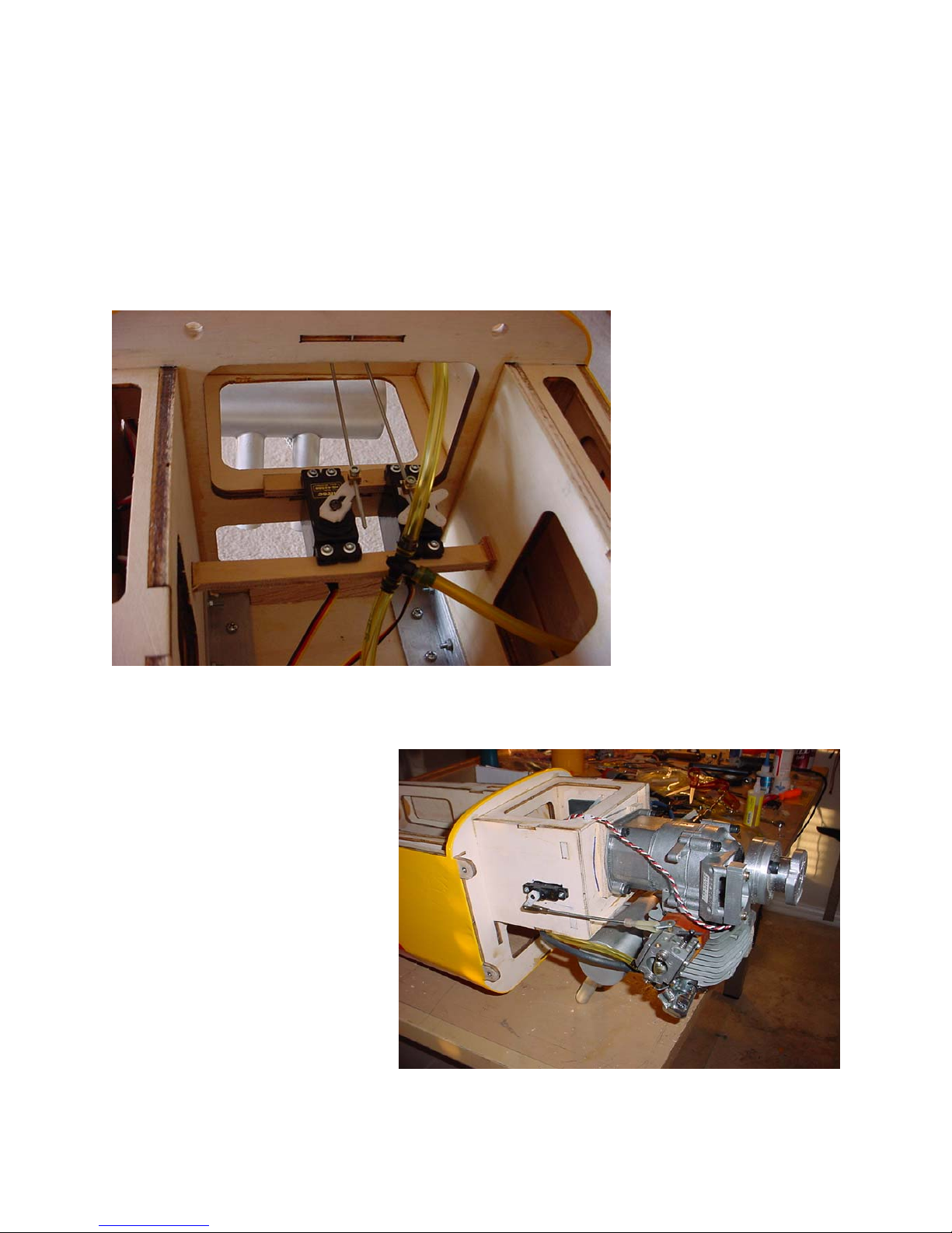
It is impossible for us to anticipate every potential throttle layout for every engine,
so I have included photos of
two typical installations. The one above is for a DA 50 with rear carb, but presumably could
apply to any rear carb engine. Notice that all we did is add two lite ply supports behind the motor box.
Another installation is shown below,
this is a G62 which has a side carb
setup. This photo does not show the
choke installation, it required removal of the factory installed arm
and installation of a new one in the
proper orientation.
Never attach pushrods to the engine
with metal connector. There must be
an insulator between the engine and
any extension or it can act as an antenna transmitting RF signals.
Page 19
28% Cap 232 Assembly Manual
Step 8. Install the landing gear
There should be drilled holes in the landing gear plate under the covering, these should
match up with the holes in the landing gear. Unfortunately the holes are not always there. To
assure perfect alignment use the following procedure. If the holes are not there center the
gear so the holes align with the aluminum
bracket inside. The front edge of the gear
should be back about 1/2 to 3/4 inch from the
front fuselage former edge. Drill one of these
holes through the aluminum bracket and mount
the landing gear with 4mm screws and locknuts. Then use the landing gear as a template
and drill the remaining holes as well and use
4mm screws and locknuts there also. Keep the
front edge of the gear parallel with the front
former.
To mount the wheel pants you simply drill
through the back of the landing gear and through the wood backing plate. Install a 4-40
blind nut in that wood backing plate.
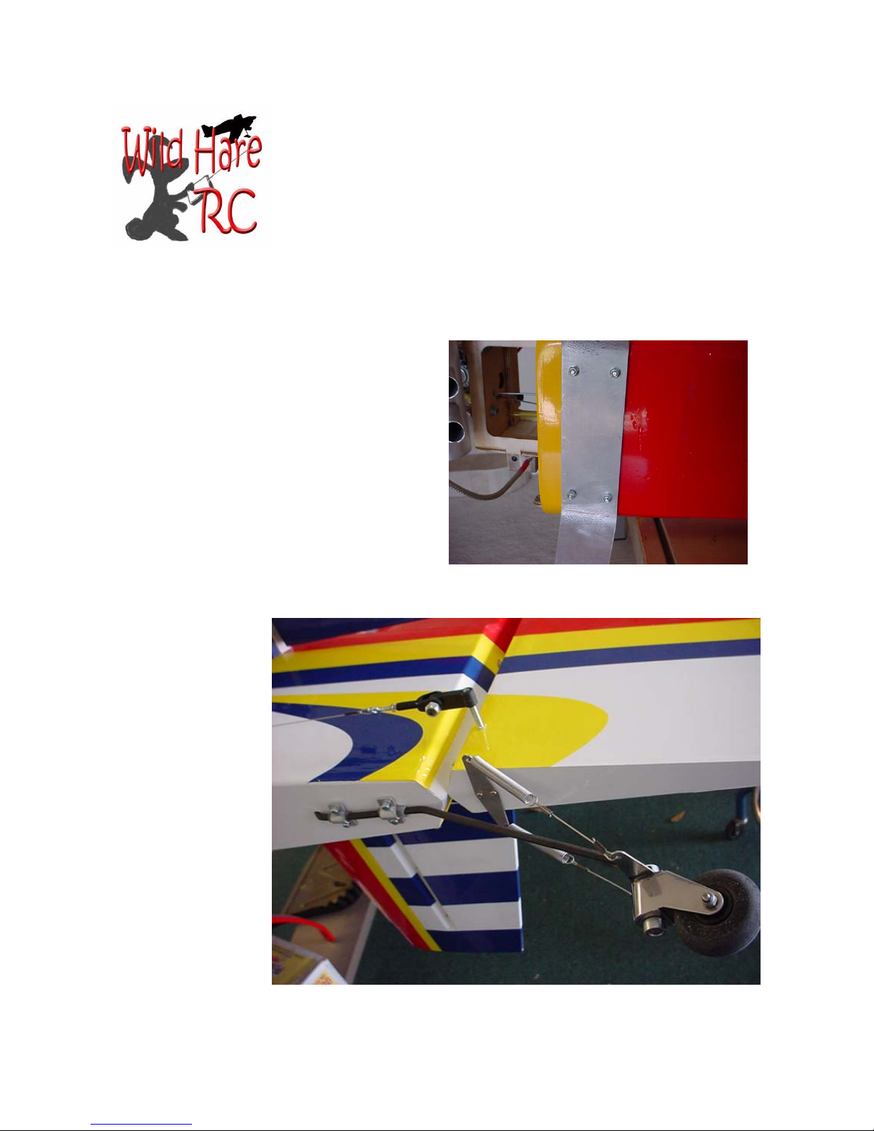
The tail wheel wire
attaches to the hardwood plate at the bottom of the tail using
two wood screws on
each of two retaining
brackets.. The hole
for the wire is predrilled. Use springs
from the tailwheel
tiller for controlling
the tailwheel. See the
accompanying photo.
The springs protect
the rudder servo(s)
from damage.
Page 20
28% Cap 232 Assembly Manual
Steps 9, 10, 11. Installation of fuel system, radio and control linkages
These 3 subjects are combined on one page because this is the part where you get to do
things your way. We have only done a few things to get you started.
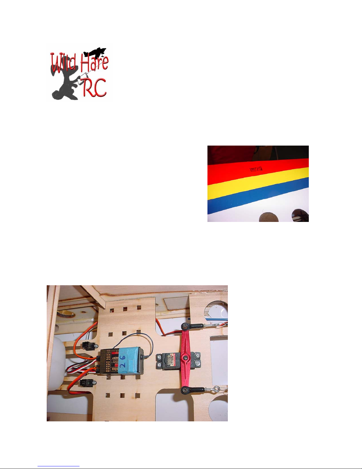
1. There is plenty of room to cut holes in one or both fuse sides that will fit the popular integrated switch/charge jack assemblies. These are
available from Maxx Products, Cermark, JR, and
probably several other vendors. Some trimming
may be required. Since the fuse sides are balsa new
holes are easily cut with a razor knife. If you do
cut into the fuse side for any reason do not cut
the 1/4” balsa stringers at the top and bottom of
each side.
2. The fuel tank can be mounted on the tray beneath
the wing tube. Putting it there minimizes changes
in balance as the engine burns off fuel.
3. There is a tray which is meant to hold the receiver, battery pack(s), and one or two rudder servos if a pull-pull is chosen.
4. In case you need to add weight in the front of the plane for balancing, the sides of the
motor box at the front are a good place to mount the receiver packs. Range check your
radio with the engine running before flying to be sure
no interference is being
caused by the batteries being
in close proximity to the engine’s ignition system.
Page 21
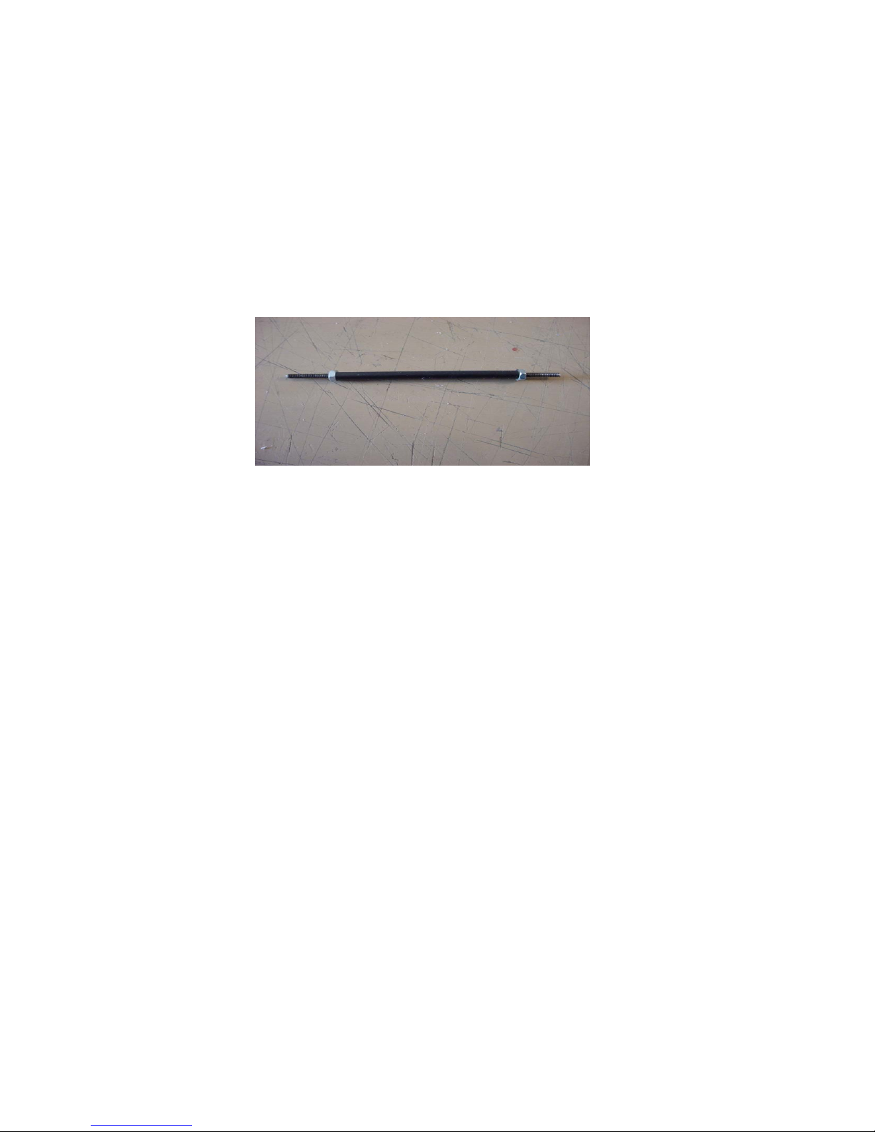
Please use good strong pushrods and other linkage parts. A sample of the assembly that we
used is shown in the picture below. Notice we use carbon fiber pushrods and Dubro HD horns.
The servo connection is done with Sullivan 4-40 or Dubro clevises, or with HD 4-40 ball links.
Avoid using ball-links with plastic servo arms, they generate a twisting force on the servo arms
that will fatigue and fail.
Making pushrods that will withstand the forces involved in a large plane of this type is very
simple once you see how it is done. If you have your own design, feel free to use it, but here’s
one that is cheap and strong.
You will need a length of 3/16” carbon fiber or fiberglass tubing, a length of 4-40 all-thread
rod, and some 4-40 nuts. All this hardware is included in our optional hardware kit.
First, set up your linkage using the clevises and the 4-40 all thread cut to the proper length. You
can make all your pushrods at once, so get all those rods set to the right length. If you use a
metal clevis, be sure the pushrod goes all the way into the threaded section, plus a little to allow
a range of adjustment. With plastic clevises like Dubro or Rocket City, the rod should screw
into the clevis about 1/2 inch to be sure there is sufficient strength.
Measure each pushrod, and cut a piece of carbon-fiber tube that is 1 1/2” shorter than the rod.
Slip the tube over the rod and tighten down a nut from each end so that you leave an equal
amount of thread at each end to mount the clevis. Tighten the nuts slightly so they don’t come
loose and so there is a little tension on the rod inside the tube.
You’re done. Install the pushrods.
Page 22
28% Cap 232 Assembly Manual
Step 12. Mounting the wings
Push the 1.25 inch aluminum tube spar through the tube in the fuselage until it protrudes an
equal distance on both sides. Carefully push each wing onto the tube until the anti-rotation dowels engage the holes in the fuselage side. As the wing approaches the fuselage guide the aileron
extension through the access hole or if you used servo extensions glued to the fuse side just
plug them in.
The wings mount to the fuselage with one 1/4”-20 screw on each wing through the fuselage
side. I use nylon screws because they are more resistant to vibration.
The wing retainer screws are in an awkward location. On my test planes I installed a stud in
one wing. To assemble the plane I first put on the wing that used the screw, inserted the nylon
screw and used a long screwdriver straight through the fuse from the other side to tighten it.
Then I put on the wing with the stud and used a wing nut to retain that wing.
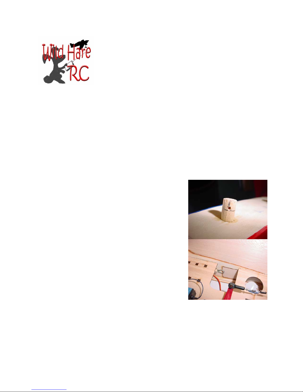
You can also drill the antirotation dowels to accept hairpins
for safety (see photo). Use no larger than a 1/16” drill and pin
to avoid weakening the dowel. Do not rely on the dowels
alone, they are not meant to be used as permanent retainers but
will work in an emergency.
If the holes for the screws or for the dowels do not line up exactly you can use a rat-tail rasp to elongate the holes slightly.
Avoid enlarging the holes for the a/r dowels in a vertical orientation which could change the wing incidence setting.
Page 23
28% Cap 232 Assembly Manual
Steps 13 and 14. Balance the plane and adjust control
throws
The first flight should be done with the plane balanced as shown in table below. If you can get
it to balance a little farther forward it will add stability.
point. When making CG changes always do it a little at a time or you could find yourself flying
a plane that cannot be landed.
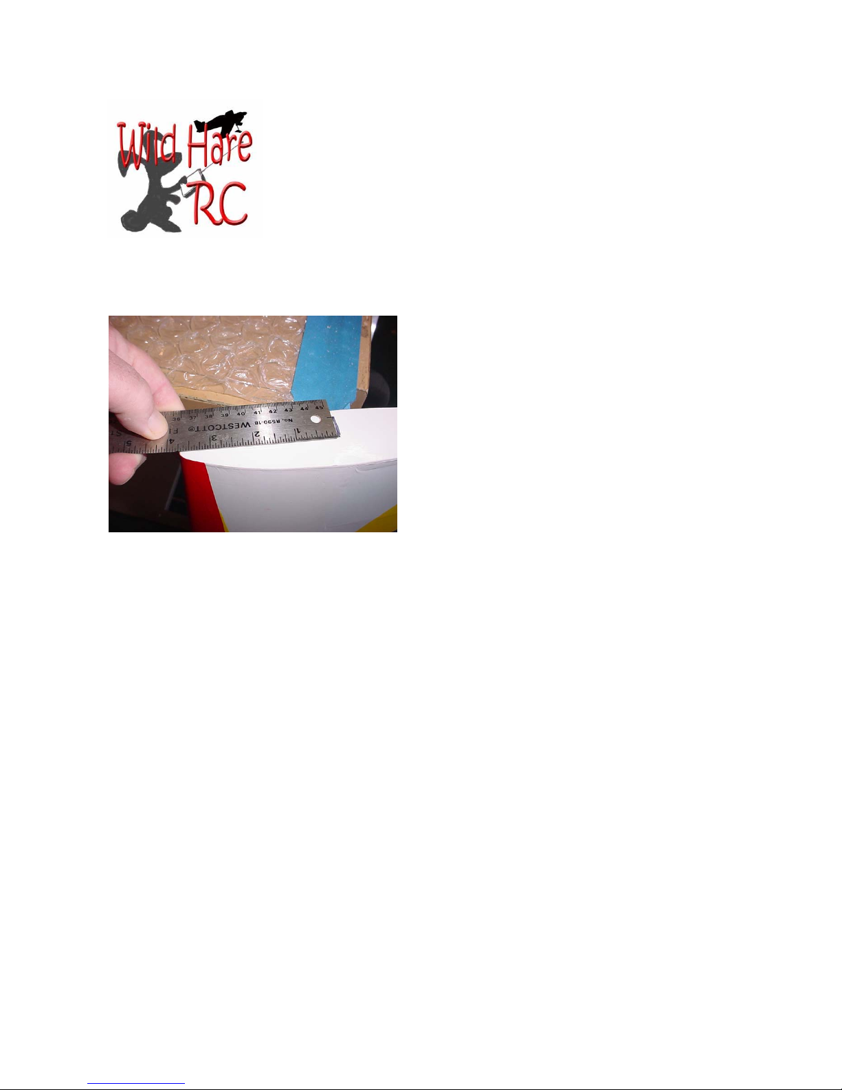
Balance the plane 3 1/2” to 4” behind
leading edge at wing tip.
If your plane is tail heavy, consider moving batteries as far forward as possible, remove anything
from the tail that might be adding weight, get a
lighter tailwheel, heavier ignition battery. Remember that the farther weight is from the CG the less
of it you will need. A small weight on a long arm
makes a big difference. A heavy spinner has more
effect that a bigger battery because it is farther
from the CG. Your flying style may require a different balance point, but this is a good safe starting
Control Throws
We set the control throws as follows on planes in test. Please keep in mind the high rates specified here are for 3d, not for just faster response. The elevator in particular at these rates will
cause instant stalling, tumbling, and all sorts of other things that can only be done at low
speeds. Do not use the 3d settings until you are thoroughly familiar with the plane on low
rates.
High rate (3D) Low rate
Ailerons 23 deg 16 deg
Elevators 40+ deg. 12 deg. is plenty
Rudder 45 deg. 25 deg.
Fly the plane on low rates at first. At high 3d rates it is very difficult to fly. The 3d rates
are intended only for extreme aerobatics.
 Loading...